EP3669963B1 - Tropfenabscheider mit neuer verbindungsstruktur - Google Patents
Tropfenabscheider mit neuer verbindungsstruktur Download PDFInfo
- Publication number
- EP3669963B1 EP3669963B1 EP19217365.6A EP19217365A EP3669963B1 EP 3669963 B1 EP3669963 B1 EP 3669963B1 EP 19217365 A EP19217365 A EP 19217365A EP 3669963 B1 EP3669963 B1 EP 3669963B1
- Authority
- EP
- European Patent Office
- Prior art keywords
- separator
- rail
- spacer
- spacers
- mist eliminator
- Prior art date
- Legal status (The legal status is an assumption and is not a legal conclusion. Google has not performed a legal analysis and makes no representation as to the accuracy of the status listed.)
- Active
Links
Images


Classifications
-
- B—PERFORMING OPERATIONS; TRANSPORTING
- B01—PHYSICAL OR CHEMICAL PROCESSES OR APPARATUS IN GENERAL
- B01D—SEPARATION
- B01D45/00—Separating dispersed particles from gases or vapours by gravity, inertia, or centrifugal forces
- B01D45/04—Separating dispersed particles from gases or vapours by gravity, inertia, or centrifugal forces by utilising inertia
-
- B—PERFORMING OPERATIONS; TRANSPORTING
- B01—PHYSICAL OR CHEMICAL PROCESSES OR APPARATUS IN GENERAL
- B01D—SEPARATION
- B01D45/00—Separating dispersed particles from gases or vapours by gravity, inertia, or centrifugal forces
- B01D45/04—Separating dispersed particles from gases or vapours by gravity, inertia, or centrifugal forces by utilising inertia
- B01D45/08—Separating dispersed particles from gases or vapours by gravity, inertia, or centrifugal forces by utilising inertia by impingement against baffle separators
Definitions
- the present patent application relates to a droplet separator for separating liquids from a gas flow, having at least two separator lamellae arranged parallel to one another and at least one spacer arranged transversely to the longitudinal direction of the separator lamellae and holding the separator lamellae at a distance from one another, with at least one of the spacers being transverse to the longitudinal direction and transverse to the height of the
- a rail is arranged in the edge regions of the at least one spacer that run along the separator lamellae, the at least one spacer has at least one first locking device, the rail has at least one second locking device and the at least one first locking device and the at least one second locking device engage in a form-fitting manner and the separator lamellae with the at least one Lock the spacer and the rail.
- Such droplet separators are used to separate liquid droplets located in a gas flow. Such liquid droplets can arise as a result of condensation processes, for example after cooling through targeted spraying of liquid, through absorption and washing processes, through entrainment from a gas-liquid mixture, etc.
- droplet separators are required, which optimize chemical and especially petrochemical processes by removing disruptive liquid components, avoid condensate contamination, recover valuable liquid components, ensure compliance with emission values and prevent corrosion and erosion processes.
- Droplet separators use the higher inertia of liquid droplets compared to the lower inertia of the gas carrying them.
- the moist gas is guided through internals, the separator lamellae, in which the flow direction of the gas is deflected several times.
- the liquid droplets cannot follow these changes in direction, so they collide with the internals and settle there. As the liquid drops accumulate, they flow downwards.
- Droplet separators are usually used in the area of the apparatus outlet, for example at the top of the column, or in connection with a collection tray between two packing stages. This minimizes liquid discharge from the column or liquid entrainment from one stage to the next.
- the flow direction of the gas is deflected by separator lamellae which have a (multiple) curved cross section. At least two separator lamellae are arranged in parallel next to one another.
- the separator bars are connected to spacers, which spacers keep the separator bars parallel and spaced apart.
- Such a droplet is, for example, in WO2018/149433 A1 shown. It is described there that the separator lamellae are welded to end walls designed as spacers. The separator layers thus formed are connected to a supporting structure via plug-in connections.
- the droplet separator comprises one or more droplet separator packages with at least two elongated lamellar droplet separator profiles arranged parallel to one another. At least one end of the lamellar droplet separator profiles are arranged holding strips between adjacent lamellar droplet separator profiles. One of the side surfaces of the holding strips is provided with protruding locking pins, the respective other side surface of the holding strips has locking recesses.
- the lamella droplet separator profiles have holes at their ends through which the locking pins of the retaining strips can be passed.
- the locking pins of the holding rails are passed through the holes in the ends of the lamellar droplet separator profiles, inserted into the locking recesses of the next holding rails and locked there.
- tubular, slotted clamping elements can be provided which engage in transverse grooves at the upper and lower end region of the holding strips and clamp the holding strips of two droplet separator packs arranged opposite one another.
- the object of the present invention is to provide a droplet separator that is easy to produce, enables a secure connection between the separator lamellae and the spacers, and is corrosion-resistant.
- the invention provides that the at least one first locking device of the at least one spacer as a projecting element in the form of a strip is formed, the at least one second locking device of the rail is formed as a recess in the form of an opening in the rail, through which the strip is passed and the part of the strip of the at least one spacer that projects out of the opening in the rail is bent over.
- the connection between the separator lamellae, the spacers and the rail is therefore purely positive. This eliminates the need for welded joints in the droplet separator.
- the locking devices ensure a secure and stable connection of the spacers to the separator lamellae.
- the protruding element, ie the first locking device is designed in one piece with the spacer.
- the second locking means is formed through the opening in the rail and is thus formed integrally with the rail.
- the protruding element, ie the strip engages in the recess, as a result of which the positive connection between the rail and the at least one spacer and thus also the separator lamellae is formed.
- the part of the strip of the at least one spacer that projects out of the opening in the rail is bent over, a secure and stable positive locking can be achieved between the at least one spacer and the rail.
- the strip is therefore in contact with an outside of the rail, so that the strip is prevented from slipping out of the rail and secure attachment is achieved.
- a stable connection of the separator lamellae with the spacers and the rail is achieved when the rail has a U-shaped cross section and surrounds the edge area of the at least one spacer on both sides.
- the stability of the droplet separator can be further increased if its rail is arranged on both edge regions of the at least one spacer running transversely to the longitudinal direction and transversely to the height of the separator lamellae.
- the at least one spacer is plate-shaped and the protruding element lies in the plane of the at least one spacer.
- the spacer can then simply be stamped out of sheet metal.
- the shape of the sides of the at least one spacer, with which the spacer bears against the separator lamellae, corresponds to the cross-sectional shape of the separator lamellae and is therefore also multiply curved.
- the stability of the entire droplet separator can be further increased by providing at least one of the separator lamellae with a recess into which the at least one rail engages. This creates an additional plug-in connection between the rail or rails and the separator lamellae, which prevents possible axial movement of the separator lamellae.
- the droplet separator can comprise a plurality of separator lamellae arranged parallel to one another, with adjacent separator lamellae being held at a distance from one another by spacers, the spacers lying next to one another transversely to the longitudinal direction of the separator lamellae and on both edge regions running transversely to the longitudinal direction and transversely to the height of the separator lamellae adjacent spacers are each arranged a common rail, each of the spacers having a protruding strip at its upper and at its lower edge region and the protruding strips engage in corresponding openings in the respective rail.
- the spacers are next to one another, they form a spacer plate, by which the separator lamellas lying next to one another are fastened and held at a distance from one another, so that a separator lamella pack is created which can be installed easily.
- the distance between the spacer plates in the longitudinal direction of the separator lamellae is about 200 - 500 mm.
- the strips of the spacers have different lengths.
- at least a pair of the spacers preferably have strips with a greater length. This means, for example, that different installation situations for the droplet separator can be addressed. For example, shorter strips can be provided at the points where the finished droplet separator rests on a supporting structure.
- the droplet separator consists of metallic materials.
- a perspective view of a droplet separator 1 is shown from above.
- the droplet separator 1 comprises a plurality of elongated separator lamellae 2 arranged parallel next to one another.
- sixteen separator lamellae 2 are arranged next to one another.
- the separator lamellae 2 have a multiply curved cross section. In the illustrated embodiment, the cross section of the separator lamellae 2 is approximately S-shaped.
- Spacers 3 are arranged between the separator lamellae 2 perpendicular to the longitudinal direction L of the separator lamellae 2 .
- spacers 3 are attached to a front and a rear end of the separator lamellae 2 and to four spaced-apart positions between the front and the rear end of the separator lamellae 2 in the longitudinal direction L of the separator lamellae 2 .
- the at the same Position in the longitudinal direction L of the separator lamellae 2 juxtaposed spacers 3 are connected to each other along their upper and lower edge regions 4, 5 by a rail 8.
- the spacers 3 arranged next to one another and the rails 8 thus form spacer plates 9 .
- each separator lamella 2 is arranged on each side of each separator lamella 2 . This is discussed below with reference to 2 described in more detail.
- the separator lamellae 2 which are arranged parallel and spaced apart from one another, are held by six spacer plates 9 .
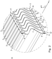
- In 2 is a in 1 shown with II designated section of the end of the droplet separator 1 in enlargement. It can be clearly seen that each spacer 3 is approximately plate-shaped and has an upper edge area 4 and a lower edge area 5 . Both the upper edge area 4 and the lower edge area 5 of the spacers 3 extend essentially perpendicularly to the longitudinal extension L and to the height H of the separator lamellae 3. The two side edges 6, 7 of the spacers 3 have a multiply curved shape that corresponds to the cross section of the Separator lamellae 2 corresponds. The spacers 3 are arranged between the separator lamellae 2, nestle with their side edges 6, 7 on the separator lamellae 2 and keep the separator lamellae 2 spaced apart from one another.
- the spacers 3 between the individual separator lamellae 2 are at the same position in the longitudinal direction L of the separator lamellae 2 and are each surrounded by a rail 8 at their upper edge area 4 and their lower edge area 5 .
- Each rail 8 has a U-shaped cross section and surrounds the respective edge area 4, 5 of the spacers 3 on both sides.
- each rail 8 has a plurality of second locking devices in the form of openings 10 .
- the number of openings 10 in each rail 8 corresponds to the number of spacers 3 enclosed by the respective rail 8 .
- the openings 10 are arranged in the transverse web 11 of the U-shaped rail 8 .
- the position of the openings 10 corresponds approximately to the middle of the spacer 3 arranged underneath.
- Each spacer 3, 3' has on its upper edge area 4 and on its lower edge area 5 a first locking device in the form of a protruding strip 12, 12'.
- the strips 12, 12' lie in one plane with the remaining area of the spacer 3.
- the strips 12, 12' are arranged centrally on the respective edge area 4, 5.
- Each strip 12, 12' extends through one of the openings 10 in the rails 8.
- the strips 12' of every fifth spacer 3' are somewhat longer than the strips 12 of the other spacers 3.
- the longer strips 12' are beaded, ie bent over, and lie on one side of the rail 8 in question.
- the flanged strips 12' of the spacers 3' and the associated openings 10 of the rails 8 form a positive locking mechanism which holds the rails 8, the spacers 3, 3' and the separator lamellae 2 together.
- more or fewer spacers have a strip with a greater length, which is passed through the corresponding opening in the respective rail and crimped.
- the strips of all spacers can be crimped or only the strips of every seventh spacer.
- FIG. 3 shows a side view of a portion of the droplet separator 1 from 1 . This is the side view of one of the areas of the separator lamellae 2 on which spacers 3 are arranged. The upper area of the outermost separator lamella 2 and one of the outermost spacers 3' can be seen. In 3 the spacers 3, 3' are arranged one behind the other in the image plane.
- the U-shaped rail 8 is plugged onto the upper edge region 4 of the spacers 3, 3'.
- the upper strip 12 'of the outermost spacer 3' is passed through the opening 10 of the rail 8 and flanged so that it rests on the outside of the rail 8.
- the separator lamellae 2 arranged parallel and spaced apart from one another have a recess 14 at their upper edge 13 and at their lower edge (not shown), at the position at which the spacers 3 are arranged, into which the U-shaped rails 8 engage .
- the droplet separator 1 is therefore very stable and can be easily handled, transported and assembled.
- the droplet separator 3' is essentially plate-shaped.
- the protruding strips 12' are formed approximately centrally on the upper edge area 4 and on the lower edge area 5 of the spacer 3'.
- the protruding strips 12' lie in the same plane as the rest of the spacer 3'.
- the shape of the side edges 6, 7 of the spacer 3' corresponds to the cross-sectional shape of the separator lamellae 2.
- the side edges 6, 7 of the spacer 3' are therefore also multiply curved.
- the strips 12' have a first length l1, which is sufficient to guide the strips 12' through the corresponding opening 10 in the rail 8 and to bead them, ie to bend them.
- figure 5 shows a further spacer 3, which is in the figures 1 and 2 between two spacers 3' with a longer strip 12' is arranged.
- the spacer 3 is essentially identical in construction to the spacer 3' 4 with the difference that the protruding strip 12 has a second length l2.
- the second length 2 is smaller than the first length l1.
- the spacers 3, 3' are preferably stamped out of sheet metal.
- the protruding elements of which, ie the strips, have a length which differs from the length l1, l2 of the strips 12, 12'. This length is preferably shorter.
- the rail 8 is designed as a profile with a U-shaped cross section.
- the openings 10 through which the strips 12, 12' of the spacers extend are formed in the upper region of the rail 8, that is to say in the transverse web 11 of the U-shaped profile.
- All components of the droplet separator are preferably made of a metallic material.
Landscapes
- Chemical & Material Sciences (AREA)
- Chemical Kinetics & Catalysis (AREA)
- Separating Particles In Gases By Inertia (AREA)
- Filtering Of Dispersed Particles In Gases (AREA)
- Fuel Cell (AREA)
- Filtering Materials (AREA)
- Cell Separators (AREA)
Description
- Die vorliegende Patentanmeldung betrifft einen Tropfenabscheider zur Abscheidung von Flüssigkeiten aus einem Gasstrom mit mindestens zwei parallel zueinander angeordneten Abscheiderlamellen und mindestens einem quer zur Längsrichtung der Abscheiderlamellen angeordneten, die Abscheiderlamellen beabstandet zueinander haltenden Abstandshalter, wobei an mindestens einem der quer zur Längsrichtung und quer zur Höhe der Abscheiderlamellen verlaufenden Randbereiche des mindestens einen Abstandshalters eine Schiene angeordnet ist, der mindestens eine Abstandshalter mindestens eine erste Verriegelungseinrichtung aufweist, die Schiene mindestens eine zweite Verriegelungseinrichtung aufweist und die mindestens eine erste Verriegelungseinrichtung und die mindestens eine zweite Verriegelungseinrichtung formschlüssig ineinandergreifen und die Abscheiderlamellen mit dem mindestens einen Abstandshalter und der Schiene verriegeln.
- Derartige Tropfenabscheider werden eingesetzt, um in einem Gasstrom befindliche Flüssigkeitströpfchen abzuscheiden. Solche Flüssigkeitströpfchen können durch Kondensationsvorgänge, beispielsweise nach Kühlung durch gezielte Flüssigkeitseinsprühung, durch Absorptions- und Waschprozesse, durch Mitriss aus einem Gas-Flüssigkeits-Gemisch, etc. entstehen. Zur Abscheidung dieser meist sehr kleinen Flüssigkeitströpfchen sind Tropfenabscheider nötig, die damit chemische, besonders auch petrochemische Prozesse durch Entfernung störender Flüssigkeitsanteile optimieren, Kondensatverunreinigungen vermeiden, wertvolle Flüssigkeitsanteile rückgewinnen, für die Einhaltung von Emissionswerten sorgen und Korrosions- und Erosionsprozesse verhindern.
- Tropfenabscheider nutzen die höhere Trägheit von Flüssigkeitstropfen gegenüber der geringeren Trägheit des sie mitführenden Gases. Hierzu wird das feuchte Gas durch Einbauten, die Abscheiderlamellen, geführt, in denen die Strömungsrichtung des Gases mehrfach umgelenkt wird. Die Flüssigkeitstropfen können diesen Richtungsänderungen nicht folgen, prallen deshalb auf die Einbauten und setzen sich dort ab. Bei zunehmender Ablagerung der Flüssigkeitstropfen fließen diese nach unten.
- Tropfenabscheider werden üblicherweise im Bereich des Apparateausgangs, also beispielsweise am Kolonnenkopf oder aber in Verbindung mit einem Sammelboden zwischen zwei Füllkörperstufen eingesetzt. Dadurch wird der Flüssigkeitsaustrag aus der Kolonne bzw. der Flüssigkeitsmitriss (Entrainment) von einer Stufe in die nächste minimiert.
- Bei einem erfindungsgemäßen Tropfenabscheider erfolgt die Umlenkung der Strömungsrichtung des Gases durch Abscheiderlamellen, die einen (mehrfach) gekrümmten Querschnitt aufweisen. Dabei sind mindestens zwei Abscheiderlamellen parallel nebeneinander angeordnet. Die Abscheiderlamellen sind mit Abstandshaltern verbunden, wobei die Abstandshalter die Abscheiderlamellen parallel und in einem Abstand zueinander halten.
- Ein derartiger Tropfenabscheider ist beispielsweise in der
WO2018/149433 A1 gezeigt. Dort wird beschrieben, dass die Abscheiderlamellen mit als Abstandshaltern ausgebildeten Endwänden verschweißt sind. Die dadurch ausgebildeten Abscheiderlagen sind über Steckverbindungen mit einer Tragkonstruktion verbunden. - Nachteilig an derartigen Konstruktionen ist, dass die Schweißverbindungen relativ aufwändig in der Herstellung sind, Nachbearbeitung, wie z.B. Beizen mit den damit verbundenen Nachteilen, erfordern und sehr korrosionsanfällig ist.
- Ferner ist aus der
DE 20 2011 106925 U1 ein weiterer Tropfenabscheider bekannt. Der Tropfenabscheider umfasst ein oder mehrere Tropfenabscheiderpakete mit mindestens zwei parallel zueinander angeordneten länglichen Lamellentropfenabscheiderprofilen. An mindestens einem Ende der Lamellentropfenabscheiderprofile sind Halteleisten zwischen benachbarten Lamellentropfenabscheiderprofilen angeordnet. Eine der Seitenflächen der Halteleisten ist mit vorstehenden Rastzapfen versehen, die jeweils andere Seitenfläche der Halteleisten weist Rastvertiefungen auf. Die Lamellentropfenabscheiderprofile weisen an ihren Enden Löcher auf, durch die die Rastzapfen der Halteleisten hindurchgeführt werden können. Bei dem Zusammenbau eines Tropfenabscheiderpakets werden die Rastzapfen der Halteleisten durch die Löcher in den Enden der Lamellentropfenabscheiderprofile hindurchgeführt, in die Rastvertiefungen der nächsten Halteleisten eingesteckt und dort verrastet. Um nebeneinanderliegende Tropfenabscheiderpakete miteinander zu verbinden, können rohrförmige, geschlitzte Klemmelemente vorgesehen sein, die in Quernuten am oberen und unteren Endbereich der Halteleisten eingreifen und die gegenüber angeordneten Halteleisten von zwei Tropfenabscheiderpaketen miteinander verklemmen. - Aufgabe der vorliegenden Erfindung ist es, einen Tropfenabscheider bereitzustellen, der einfach herstellbar ist, eine sichere Verbindung zwischen den Abscheiderlamellen und den Abstandshaltern ermöglicht und korrosionsbeständig ist.
- Hierzu ist erfindungsgemäß vorgesehen, dass die mindestens eine erste Verriegelungseinrichtung des mindestens einen Abstandshalters als vorspringendes Element in Form eines Streifens ausgebildet ist, die mindestens eine zweite Verriegelungseinrichtung der Schiene als Ausnehmung in Form einer Öffnung in der Schiene ausgebildet ist, durch die der Streifen durchgeführt ist und der aus der Öffnung der Schiene hinausragende Teil des Streifens des mindestens einen Abstandshalters umgebogen ist.
- Die Verbindung zwischen den Abscheiderlamellen, den Abstandshaltern und der Schiene erfolgt also rein formschlüssig. Dadurch werden Schweißverbindungen in dem Tropfenabscheider überflüssig. Durch die Verriegelungseinrichtungen wird dennoch eine sichere und stabile Verbindung der Abstandshalter mit den Abscheiderlamellen realisiert. Das vorspringende Element, also die erste Verriegelungseinrichtung, ist einstückig mit dem Abstandshalter ausgebildet. Die zweite Verriegelungseinrichtung wird durch die Öffnung in der Schiene ausgebildet und ist somit einstückig mit der Schiene ausgebildet. Das vorspringende Element, also der Streifen, greift in die Ausnehmung ein, wodurch die formschlüssige Verbindung zwischen der Schiene und dem mindestens einen Abstandshalter und damit auch den Abscheiderlamellen ausgebildet ist. Dadurch, dass der aus der Öffnung der Schiene hinausragende Teil des Streifens des mindestens einen Abstandshalters umgebogen ist, kann eine sichere und stabile formschlüssige Verriegelung zwischen dem mindestens einen Abstandshalter und der Schiene erreicht werden. Der Streifen liegt also an einer Außenseite der Schiene an, so dass ein Herausrutschen des Streifens aus der Schiene verhindert wird und eine sichere Befestigung erzielt ist.
- Eine stabile Verbindung der Abscheiderlamellen mit den Abstandshaltern und der Schiene wird erzielt, wenn die Schiene einen u-förmigen Querschnitt aufweist und den Randbereich des mindestens einen Abstandshalters auf beiden Seiten umgibt.
- Die Stabilität des Tropfenabscheiders kann weiter erhöht werden, wenn an beiden quer zur Längsrichtung und quer zur Höhe der Abscheiderlamellen verlaufenden Randbereiche des mindestens einen Abstandshalter seine Schiene angeordnet ist.
- In noch einer weiteren Variante kann vorgesehen sein, dass der mindestens eine Abstandshalter plattenförmig ausgebildet ist und das vorspringende Element in der Ebene des mindestens einen Abstandshalters liegt. Der Abstandshalter kann dann einfach aus Blech ausgestanzt werden. Dabei entspricht die Form der Seiten des mindestens einen Abstandhalters, mit denen der Abstandshalter an den Abscheiderlamellen anliegt, der Querschnittsform der Abscheiderlamellen und ist daher ebenfalls mehrfach gekrümmt.
- Die Stabilität des gesamten Tropfenabscheiders kann dadurch weiter erhöht werden, dass mindestens eine der Abscheiderlamellen mit einer Aussparung versehen ist, in die die mindestens eine Schiene eingreift. Dadurch wird eine zusätzliche Steckverbindung zwischen der Schiene bzw. den Schienen und den Abscheiderlamellen geschaffen, durch die eine mögliche Axialbewegung der Abscheiderlamellen verhindert wird.
- In noch einer weiteren Ausführungsform kann der Tropfenabscheider eine Mehrzahl von parallel zueinander angeordneten Abscheiderlamellen umfassen, wobei nebeneinanderliegende Abscheiderlamellen durch Abstandshalter beanstandet zueinander gehalten sind, die Abstandshalter quer zur Längsrichtung der Abscheiderlamellen nebeneinanderliegen und an beiden quer zur Längsrichtung und quer zur Höhe der Abscheiderlamellen verlaufenden Randbereichen der nebeneinanderliegenden Abstandshalter je eine gemeinsame Schiene angeordnet ist, wobei jeder der Abstandshalter an seinem oberen und an seinem unteren Randbereich einen vorstehenden Streifen aufweist und die vorstehenden Streifen in entsprechende Öffnungen in der jeweiligen Schiene eingreifen. Dadurch, dass die Abstandshalter nebeneinanderliegen, bilden sie eine Abstandshalterplatte aus, durch die die nebeneinanderliegenden Abscheiderlamellen beabstandet zueinander befestigt und gehalten werden, so dass ein Abscheiderlamellenpaket entsteht, das einfach eingebaut werden kann.
- Vorzugsweise kann ferner vorgesehen sein, dass an jeder Abscheiderlamelle mehrere Abstandshalter in Längsrichtung der Abscheiderlamellen beanstandet zueinander angeordnet sind, wobei die Abstandshalter nebeneinanderliegende Abscheiderlamellen, die an derselben Position in Längsrichtung der Abscheiderlamellen liegen, am beiden quer zur Längsrichtung und quer zur Höhe der Abscheiderlamellen verlaufenden Randbereichen mit je einer gemeinsamen Schiene verriegelt sind. Entlang der Längsrichtung der Abscheiderlamellen sind diese also an mehreren Punkten mittels der Abstandshalter aneinander befestigt. Der Abstand der Abstandshalterplatten zueinander in Längsrichtung der Abscheiderlamellen beträgt dabei etwa 200 - 500mm. Die dadurch ausgebildeten Abscheiderlamellenpakete sind sehr stabil und können einfach gehandhabt, transportiert und eingebaut werden.
- In noch einer weiteren Variante kann vorgesehen sein, dass die Streifen der Abstandshalter eine unterschiedliche Länge aufweisen. Vorzugsweise weisen bei nebeneinander angeordneten Abstandshaltern zumindest ein paar der Abstandshalter Streifen mit einer größeren Länge auf. Dadurch kann beispielweise auf unterschiedliche Einbausituationen des Tropfenabscheiders eingegangen werden. So können z.B. an den Stellen, an denen der fertige Tropfenabscheider auf einer Tragkonstruktion aufliegt, kürzere Streifen vorgesehen werden.
- Um die Herstellung und Montage des Tropfenabscheiders zu vereinfachen, kann vorgesehen werden, dass nur ein Teil der vorstehenden Streifen der Abstandshalter umgebogen sind. So ist es ausreichend, dass in einer Reihe nebeneinander angeordneter Abstandshalter, die an mindestens einem ihrer Randbereiche von derselben Schiene umschlossen sind, der/die Streifen von jedem dritten, bevorzugt jedem fünften Abstandshalter umgebogen sind.
- Um eine einfache Herstellung, hohe Stabilität und gute Beständigkeit des Tropfenabscheiders zu erhalten, kann vorgesehen sein, dass der Tropfenabscheider aus metallischen Werkstoffen besteht.
- Im Folgenden wird die Erfindung anhand von Figuren genauer beschrieben. Es zeigen:
-
Fig. 1 : perspektivische Darstellung eines erfindungsgemäßen Tropfenabscheiders von oben, -
Fig. 2 : vergrößerte Darstellung eines Endbereichs des Tropfenabscheiders ausFig. 1 , -
Fig. 3 : Seitenansicht einer Verbindungsstelle zwischen Abscheiderlamellen und einem Abstandshalter des Tropfenabscheiders ausFig. 1 , -
Fig. 4 : erste Ausführungsform eines Abstandshalters des Tropfenabscheiders ausFig. 1 , -
Fig. 5 : zweite Ausführungsform eines Abstandshalters des Tropfenabscheiders ausFig. 1 und -
Fig. 6 : Seitenansicht einer Schiene des Tropfenabscheiders das ausFig. 1 - In
Fig. 1 ist eine perspektivische Darstellung eines Tropfenabscheiders 1 von oben gezeigt. Der Tropfenabscheider 1 umfasst eine Mehrzahl von langgestreckten, parallel nebeneinander angeordneten Abscheiderlamellen 2. Im gezeigten Ausführungsbeispiel sind sechzehn Abscheiderlamellen 2 nebeneinander angeordnet. Wie an der Stirnseite des Tropfenabscheiders 1 deutlich zu erkennen, haben die Abscheiderlamellen 2 einen mehrfach gekrümmten Querschnitt. Im dargestellten Ausführungsbeispiel ist der Querschnitt der Abscheiderlamellen 2 in etwa S-förmig. - Senkrecht zur Längsrichtung L der Abscheiderlamellen 2 sind zwischen den Abscheiderlamellen 2 Abstandshalter 3 angeordnet. In
Fig. 1 sind jeweils an einem vorderen und an einem hinteren Ende der Abscheiderlamellen 2 sowie an vier zwischen dem vorderen und dem hinteren Ende der Abscheiderlamellen 2 in Längsrichtung L der Abscheiderlamellen 2 beanstandet zueinander angeordneten Positionen Abstandshalter 3 angebracht. Die an der gleichen Position in Längsrichtung L der Abscheiderlamellen 2 nebeneinander angeordneten Abstandshalter 3 sind entlang ihrer oberen und unteren Randbereiche 4, 5 durch eine Schiene 8 miteinander verbunden. Die nebeneinander angeordneten Abstandshalter 3 und die Schienen 8 bilden somit Abstandshalterplatten 9 aus. Dabei ist auf jeder Seite jeder Abscheiderlamellen 2 ein Abstandshalter 3 angeordnet. Dies wird in Folgenden unter Bezug aufFig. 2 noch genauer beschrieben. InFig. 1 sind die parallel und beabstandet zueinander angeordneten Abscheiderlamellen 2 durch sechs Abstandshalterplatten 9 gehalten. - In
Fig. 2 ist ein inFig. 1 mit II bezeichneter Ausschnitt des Endbereichs des Tropfenabscheiders 1 in Vergrößerung gezeigt. Es ist deutlich zu erkennen, dass jeder Abstandshalter 3 in etwa plattenförmig ist und einen oberen Randbereich 4 und einen unteren Randbereich 5 aufweist. Sowohl der obere Randbereich 4 als auch der untere Randbereich 5 der Abstandshalter 3 erstreckt sich im Wesentlichen senkrecht zur Längserstreckung L und zur Höhe H der Abscheiderlamellen 3. Die beiden Seitenränder 6, 7 der Abstandshalter 3 weisen eine mehrfach gekrümmte Form auf, die dem Querschnitt der Abscheiderlamellen 2 entspricht. Die Abstandshalter 3 sind zwischen den Abscheiderlamellen 2 angeordnet, schmiegen sich mit ihren Seitenränder 6, 7 an die Abscheiderlamellen 2 und halten die Abscheiderlamellen 2 so beabstandet zueinander. - Die Abstandhalter 3 zwischen den einzelnen Abscheiderlamellen 2 liegen an der gleichen Position in Längsrichtung L der Abscheiderlamellen 2 und sind jeweils an ihrem oberen Randbereich 4 und ihrem unteren Randbereich 5 von einer Schiene 8 umgeben. Jede Schiene 8 hat einen u-förmigen Querschnitt und umgibt den jeweiligen Randbereich 4, 5 der Abstandshalter 3 auf beiden Seiten. Zudem weist jede Schiene 8 eine Mehrzahl von zweiten Verriegelungseinrichtungen in Form von Öffnungen 10 auf. Die Anzahl der Öffnungen 10 in jeder Schiene 8 entspricht der Anzahl der von der jeweiligen Schiene 8 umschlossenen Abstandhalter 3. Die Öffnungen 10 sind im Quersteg 11 der u-förmigen Schiene 8 angeordnet. Die Position der Öffnungen 10 entspricht in etwa der Mitte des jeweils darunter angeordneten Abstandhalters 3.
- Jeder Abstandshalter 3, 3' weist an seinem oberen Randbereich 4 und an seinem unteren Randbereich 5 eine erste Verriegelungseinrichtung in Form eines einen überstehenden Streifen 12, 12' auf. Die Streifen 12, 12' liegen in einer Ebene mit dem restlichen Bereich des Abstandshalters 3. Die Streifen 12, 12' sind mittig an dem jeweiligen Randbereich 4, 5 angeordnet. Jeder Streifen 12, 12' erstreckt sich durch eine der Öffnungen 10 in den Schienen 8. Im dargestellten Ausführungsbeispiel sind die Streifen 12' jedes fünften Abstandshalters 3' etwas länger als die Streifen 12 der übrigen Abstandshalter 3. Die längeren Streifen 12' sind umgebördelt, also umgebogen, und liegen an einer Seite der jeweiligen Schiene 8 an. Dadurch bilden die umgebördelten Streifen 12' der Abstandshalter 3' und die zugehörigen Öffnungen 10 der Schienen 8 einen formschlüssigen Verriegelungsmechanismus aus, der die Schienen 8, die Abstandshalter 3, 3' und die Abscheiderlamellen 2 aneinander hält. Es kann auch vorgesehen werden, dass mehr oder weniger Abstandshalter einen Streifen mit einer größeren Länge aufweisen, der durch die entsprechende Öffnung in der jeweiligen Schiene geführt und umgebördelt ist. So können beispielsweise die Streifen aller Abstandshalter umgebördelt sein oder auch nur die Streifen jedes siebten Abstandshalters.
-
Fig. 3 zeigt eine Seitenansicht eines Bereichs des Tropfenabscheiders 1 ausFig. 1 . Dies ist die Seitenansicht eines der Bereiche der Abscheiderlamellen 2 an denen Abstandshalter 3 angeordnet sind. Es sind der obere Bereich der äußersten Abscheiderlamelle 2 und eines der äußersten Abstandshalter 3' zu sehen. InFig. 3 sind die Abstandshalter 3, 3' hintereinander in der Bildebene angeordnet. Auf den oberen Randbereich 4 der Abstandshalter 3, 3' ist die u-förmige Schiene 8 aufgesteckt. Der obere Streifen 12' des äußersten Abstandshalters 3' ist durch die Öffnung 10 der Schiene 8 geführt und umgebördelt, so dass er auf der Außenseite der Schiene 8 anliegt. Die parallel und beabstandet zueinander angeordneten Abscheiderlamellen 2 weisen an ihrem oberen Rand 13 und an ihrem unteren Rand (nicht dargestellt), an der Position, an der die Abstandshalter 3 angeordnet sind, eine Aussparung 14 auf, in die die u-förmigen Schienen 8 eingreifen. Dadurch wird die Position der Abscheiderlamellen 2 entlang ihrer Längsrichtung L fixiert, so dass die Abscheiderlamellen 2 nicht in Längsrichtung L durch die Abstandshalter 3, 3' rutschen können. Der Tropfenabscheider 1 ist somit sehr stabil, kann gut gehandhabt, transportiert und montiert werden. -
Fig. 4 zeigt den äußersten Abstandshalter 3' des Tropfenabscheiders ausFig. 1 . Wie bereits beschrieben ist der Tropfenabscheider 3' im wesentlichen plattenförmig. Am oberen Randbereich 4 und am unteren Randbereich 5 des Abstandshalter 3' sind in etwa mittig die vorstehenden Streifen 12' ausgebildet. Die vorstehenden Streifen 12' liegen in der gleichen Ebene wie der restliche Abstandshalter 3'. Die Form der Seitenränder 6, 7 des Abstandshalters 3' entspricht der Querschnittsform der Abscheiderlamellen 2. Die Seitenränder 6, 7 des Abstandshalters 3' sind daher ebenfalls mehrfach gekrümmt. Die Streifen 12' weisen eine erste Länge l1 auf, die ausreichend ist, um die Streifen 12' durch die entsprechende Öffnung 10 in der Schiene 8 zu führen und umzubördeln, also umzubiegen. -
Fig. 5 zeigt eine einen weiteren Abstandshalter 3, der in denFiguren 1 und2 zwischen zwei Abstandshalter 3' mit längerem Streifen 12' angeordnet ist. Der Abstandshalter 3 ist im Wesentlichen baugleich zu dem Abstandshalter 3' ausFig. 4 mit dem Unterschied, dass der vorstehende Streifen 12 eine zweite Länge l2 aufweist. Die zweite Länge 2 ist kleiner als die erste Länge l1. Vorzugsweise werden die Abstandshalter 3, 3' aus Blech ausgestanzt. - Es können auch noch weitere Abstandshalter vorgesehen sein, deren vorstehende Elemente, also die Streifen, eine Länge aufweisen, die sich von der Länge l1, l2 der Streifen 12, 12' unterscheidet. Bevorzugt ist diese Länge kürzer.
-
Fig. 6 zeigt eine Seitenansicht einer Schiene 8. Wie bereits beschrieben, ist die Schiene 8 als Profil mit einem U-förmigen Querschnitt ausgebildet. Im oberen Bereich der Schiene 8, also im Quersteg 11 des U-förmigen Profils, sind die Öffnungen 10 ausgebildet, durch die sich die Streifen 12, 12' der Abstandshalter hindurch erstrecken. - Vorzugsweise sind alle Bestandteile des Tropfenabscheiders, insbesondere aber die Abstandshalter mit den einstückig damit ausgebildeten Streifen, aus einem metallischen Werkstoff.
-
- 1
- Tropfenabscheider
- 2
- Abscheiderlamelle
- 3, 3'
- Abstandshalter
- 4
- oberer Randbereich Abstandshalter
- 5
- unterer Randbereich Abstandshalter
- 6
- Seitenrand Abstandshalter
- 7
- Seitenrand Abstandshalter
- 8
- Schiene
- 9
- Abstandshalterplatte
- 10
- Öffnung Schiene
- 11
- Quersteg Schiene
- 12, 12'
- Streifen Abstandshalter
- 13
- oberer Rand Abscheiderlamelle
- 14
- Aussparung
- L
- Längserstreckung Abscheiderlamelle
- H
- Höhe Abscheiderlamelle
- l1
- Länge Streifen 12'
- l2
- Länge Streifen 12
Claims (10)
- Tropfenabscheider (1) zur Abscheidung von Flüssigkeiten aus einem Gasstrom mit mindestens zwei parallel zueinander angeordneten Abscheiderlamellen (2) und mindestens einem quer zur Längsrichtung (L) der Abscheiderlamellen (2) angeordneten, die Abscheiderlamellen (2) beabstandet zueinander haltenden Abstandshalter (3), wobei an mindestens einem der quer zur Längsrichtung (L) und quer zu Höhe (H) der Abscheiderlamellen (2) verlaufenden Randbereiche (4, 5) des mindestens einen Abstandshalters (3) eine Schiene (8) angeordnet ist, der mindestens eine Abstandshalter (3) mindestens eine erste Verriegelungseinrichtung aufweist, die Schiene (8) mindestens eine zweite Verriegelungseinrichtung aufweist und die mindestens eine erste Verriegelungseinrichtung und die mindestens eine zweite Verriegelungseinrichtung formschlüssig ineinandergreifen und die Abscheiderlamellen (2) mit dem mindestens einen Abstandshalter (3) und der Schiene (8) verriegeln, dadurch gekennzeichnet, dass die mindestens eine erste Verriegelungseinrichtung des mindestens einen Abstandshalters (3) als vorspringendes Element in Form eines Streifens (12, 12') ausgebildet ist und die mindestens eine zweite Verriegelungseinrichtung der Schiene (8) als Ausnehmung in Form einer Öffnung (10) in der Schiene (8) ausgebildet ist, durch die der Streifen (12, 12') durchgeführt ist und der aus der Öffnung (10) der Schiene (8) hinausragende Teil des Streifens (12, 12') des mindestens einen Abstandshalters (3) umgebogen ist.
- Tropfenabscheider (1) nach Anspruch 1, dadurch gekennzeichnet, dass die Schiene (8) einen u-förmigen Querschnitt aufweist und den Randbereich (4, 5) des mindestens einen Abstandshalters (3) umgibt.
- Tropfenabscheider (1) nach Anspruch 1 oder 2, dadurch gekennzeichnet, dass an beiden quer zur Längsrichtung (L) und quer zu Höhe (H) der Abscheiderlamellen (2) verlaufenden Randbereichen (4, 5) des mindestens einen Abstandshalters (3) eine Schiene (8) angeordnet ist.
- Tropfenabscheider (1) nach einem der Ansprüche 1 bis 3, dadurch gekennzeichnet, dass der mindestens eine Abstandshalter (3) plattenförmig ausgebildet ist und das vorspringende Element in der Ebene des mindestens einen Abstandshalters (3) liegt.
- Tropfenabscheider (1) nach einem der vorherigen Ansprüche, dadurch gekennzeichnet, dass mindestens eine der Abscheiderlamellen (2) mit einer Aussparung (14) versehen ist, in die die mindestens eine Schiene (8) eingreift.
- Tropfenabscheider (1) nach einem der vorherigen Ansprüche, umfassend eine Mehrzahl von parallel zueinander angeordneten Abscheiderlamellen (2), wobei nebeneinanderliegende Abscheiderlamellen (2) durch Abstandshalter (3) beabstandet zueinander gehalten sind und die Abstandshalter (3) quer zur Längsrichtung (L) der Abscheiderlamellen (2) nebeneinanderliegen und an beiden quer zur Längsrichtung (L) und quer zu Höhe (H) der Abscheiderlamellen (2) verlaufenden Randbereichen (4, 5) der nebeneinanderliegenden Abstandshalter (3) je eine gemeinsame Schiene (8) angeordnet ist, wobei jeder der Abstandshalter (3) an seinem oberen (4) und an seinem unteren Randbereich (5) einen vorstehenden Streifen (12, 12') aufweist und die vorstehenden Streifen (12, 12') in entsprechende Öffnungen (10) in der jeweiligen Schiene (8) eingreifen.
- Tropfenabscheider (1) nach Anspruch 6, dadurch gekennzeichnet, dass an jeder Abscheiderlamelle (2) mehrere Abstandshalter (3) in Längsrichtung (L) der Abscheiderlamellen (2) beabstandet zueinander angeordnet sind, wobei die Abstandshalter (3) nebeneinanderliegen liegender Abscheiderlamellen (2), die an derselben Position in Längsrichtung (L) der Abscheiderlamellen (2) liegen, an beiden quer zur Längsrichtung (L) und quer zu Höhe (H) der Abscheiderlamellen (2) verlaufenden Randbereichen (4, 5) mit je einer gemeinsamen Schiene (8) verriegelt sind.
- Tropfenabscheider (1) nach einem der Ansprüche 6 oder 7, dadurch gekennzeichnet, dass die Streifen (12, 12') der Abstandshalter (3) eine unterschiedliche Länge aufweisen.
- Tropfenabscheider (1) nach einem der Ansprüche 6 bis 8, dadurch gekennzeichnet, dass nur ein Teil der vorstehenden Streifen (12, 12') der Abstandshalter (3) umgebogen sind.
- Tropfenabscheider (1) nach einem der vorherigen Ansprüche, dadurch gekennzeichnet, dass der Tropfenabscheider (1) aus metallischen Werkstoffen besteht.
Applications Claiming Priority (1)
| Application Number | Priority Date | Filing Date | Title |
|---|---|---|---|
| DE102018133150.9A DE102018133150A1 (de) | 2018-12-20 | 2018-12-20 | Tropfenabscheider mit neuer Verbindungsstruktur |
Publications (2)
| Publication Number | Publication Date |
|---|---|
| EP3669963A1 EP3669963A1 (de) | 2020-06-24 |
| EP3669963B1 true EP3669963B1 (de) | 2022-02-02 |
Family
ID=68944546
Family Applications (1)
| Application Number | Title | Priority Date | Filing Date |
|---|---|---|---|
| EP19217365.6A Active EP3669963B1 (de) | 2018-12-20 | 2019-12-18 | Tropfenabscheider mit neuer verbindungsstruktur |
Country Status (7)
| Country | Link |
|---|---|
| EP (1) | EP3669963B1 (de) |
| KR (1) | KR102343316B1 (de) |
| CN (1) | CN111346432B (de) |
| DE (1) | DE102018133150A1 (de) |
| DK (1) | DK3669963T3 (de) |
| ES (1) | ES2909194T3 (de) |
| TW (1) | TWI787563B (de) |
Family Cites Families (18)
| Publication number | Priority date | Publication date | Assignee | Title |
|---|---|---|---|---|
| ZA801332B (en) * | 1979-07-26 | 1981-08-26 | Xerxes Fiberglass Inc | Liquid eliminator |
| DE3039780A1 (de) * | 1980-10-22 | 1982-05-13 | GEA Kühlturmbau und Luftkondensation GmbH, 4630 Bochum | Tropfenfang |
| DE8218913U1 (de) * | 1982-07-02 | 1982-08-26 | Gesellschaft für Verfahrenstechnik mbH & Co KG, 4220 Dinslaken | Tropfenabscheider fuer luftwaescher, luftkuehler u. dgl. |
| DE19501282C2 (de) * | 1995-01-18 | 1998-07-09 | Munters Euroform Gmbh Carl | Tropfenabscheider sowie Lamellenhalter hierfür |
| DE20210293U1 (de) * | 2002-07-03 | 2002-09-05 | Ahrens, Adolf, 59510 Lippetal | Austauschbare Kassetten für Tropfenabscheider in Rauchgasentschwefelungsanlagen |
| DE102011081663A1 (de) * | 2011-08-26 | 2013-02-28 | Siemens Aktiengesellschaft | Lamellenabscheider |
| DE102011081667A1 (de) * | 2011-08-26 | 2013-02-28 | Siemens Aktiengesellschaft | Lamellenabscheider |
| DE202011106925U1 (de) * | 2011-10-18 | 2011-12-13 | Munters Euroform Gmbh | Tropfenabscheiderpaket mit verrastbaren Halteleisten |
| CN202682935U (zh) * | 2012-07-05 | 2013-01-23 | 上海瑞亚安环保设备有限公司 | 除雾器片间隔固定结构 |
| KR20140001617U (ko) * | 2012-09-11 | 2014-03-19 | 한발매스테크 주식회사 | 다중 포켓 플레이트 형 미스트 엘리미네이트의 구조. |
| CN203556218U (zh) * | 2013-09-21 | 2014-04-23 | 浙江宏电环保科技有限公司 | 一种除雾器叶片固定装置 |
| CN104888554B (zh) * | 2015-05-19 | 2016-06-29 | 北京化工大学常州先进材料研究院 | 一种除尘器 |
| CN204865263U (zh) * | 2015-06-02 | 2015-12-16 | 枣强县莱伯特环保设备有限公司 | 玻璃钢折流板除雾器 |
| CN205235588U (zh) * | 2015-12-17 | 2016-05-18 | 南京新世纪江南环保科技发展有限公司 | 一种除雾器固定件 |
| CN205549900U (zh) * | 2016-03-11 | 2016-09-07 | 河南晋开化工投资控股集团有限责任公司 | 新型高效除雾器 |
| DE102017001414B4 (de) | 2017-02-14 | 2020-06-10 | Munters Euroform Gmbh | Tropfenabscheider mit Steckverbindungen |
| DE102017001415A1 (de) * | 2017-02-14 | 2018-08-16 | Munters Euroform Gmbh | Tropfenabscheider mit geringer Bauhöhe |
| CN207385093U (zh) * | 2017-09-05 | 2018-05-22 | 上海超惠通风环保设备有限公司 | 一种防静电耐高温高效除雾器 |
-
2018
- 2018-12-20 DE DE102018133150.9A patent/DE102018133150A1/de not_active Withdrawn
-
2019
- 2019-12-05 TW TW108144588A patent/TWI787563B/zh active
- 2019-12-18 DK DK19217365.6T patent/DK3669963T3/da active
- 2019-12-18 EP EP19217365.6A patent/EP3669963B1/de active Active
- 2019-12-18 ES ES19217365T patent/ES2909194T3/es active Active
- 2019-12-19 CN CN201911317279.5A patent/CN111346432B/zh active Active
- 2019-12-20 KR KR1020190171546A patent/KR102343316B1/ko active Active
Also Published As
| Publication number | Publication date |
|---|---|
| TW202031338A (zh) | 2020-09-01 |
| DK3669963T3 (da) | 2022-02-14 |
| CN111346432B (zh) | 2021-10-15 |
| TWI787563B (zh) | 2022-12-21 |
| KR20200077452A (ko) | 2020-06-30 |
| DE102018133150A1 (de) | 2020-06-25 |
| KR102343316B1 (ko) | 2021-12-23 |
| CN111346432A (zh) | 2020-06-30 |
| ES2909194T3 (es) | 2022-05-05 |
| EP3669963A1 (de) | 2020-06-24 |
Similar Documents
| Publication | Publication Date | Title |
|---|---|---|
| EP3957940B1 (de) | Gegenstromplattenwärmetauscher-modul und gegenstromplattenwärmetauscher | |
| DE102016115030A1 (de) | Abgasmischelement | |
| EP2768596B1 (de) | Tropfenabscheiderpaket mit verrastbaren halteleisten | |
| DE2418132C2 (de) | Wärmetauscher, insbesondere Kühler für Kraftfahrzeuge | |
| DE3928234C1 (de) | ||
| EP2334887B1 (de) | Steckverbinder | |
| EP1042578A1 (de) | Steckverbinder für hohlprofile | |
| DE9310827U1 (de) | Waermetauscher aus mehreren parallel zueinander angeordneten austauscherrohren | |
| EP0340242B1 (de) | Abscheider für gasförmige fluide | |
| EP3255369A1 (de) | Rippenelement für einen wärmeübertrager | |
| DE2935158B2 (de) | Stranggepreßtes Bauelement zum Aufbau von Wänden, insbesondere von Kraftfahrzeugen | |
| EP0401590B1 (de) | Wärmetauscher | |
| EP3669963A1 (de) | Tropfenabscheider mit neuer verbindungsstruktur | |
| EP1458455B1 (de) | Halteprofil für lamellen, modulare halteprofileinheit und eine solche aufweisende abscheide-, lichtreduzier- oder strömungsleiteinheit | |
| EP0944132B1 (de) | Kabelklemme | |
| DE19858325B4 (de) | Wärmeübertrageranordnung für ein Kraftfahrzeug | |
| DE2851316A1 (de) | Element zum direkten und/oder indirekten waermeaustausch zwischen fluiden | |
| DE19816623C2 (de) | Spritzwandmodul und aus Spritzwandmodulen aufgebaute Spritzwand | |
| DE19501282A1 (de) | Tropfenabscheider sowie Lamellenhalter hierfür | |
| EP1650520A2 (de) | Wärmetauscheranordnung | |
| DE7835175U1 (de) | Element zur direkten und/oder indirekten waermeaustausch zwischen fluiden | |
| DE3539888A1 (de) | Halteleiste fuer platten | |
| DE20317987U1 (de) | Lüftungsgitter zum Be- und/oder Entlüften eines Raumes | |
| DE8910217U1 (de) | Energieführungskette | |
| DE19960596C2 (de) | Plattenförmiges Abscheiderelement |
Legal Events
| Date | Code | Title | Description |
|---|---|---|---|
| PUAI | Public reference made under article 153(3) epc to a published international application that has entered the european phase |
Free format text: ORIGINAL CODE: 0009012 |
|
| STAA | Information on the status of an ep patent application or granted ep patent |
Free format text: STATUS: THE APPLICATION HAS BEEN PUBLISHED |
|
| AK | Designated contracting states |
Kind code of ref document: A1 Designated state(s): AL AT BE BG CH CY CZ DE DK EE ES FI FR GB GR HR HU IE IS IT LI LT LU LV MC MK MT NL NO PL PT RO RS SE SI SK SM TR |
|
| AX | Request for extension of the european patent |
Extension state: BA ME |
|
| STAA | Information on the status of an ep patent application or granted ep patent |
Free format text: STATUS: REQUEST FOR EXAMINATION WAS MADE |
|
| 17P | Request for examination filed |
Effective date: 20201218 |
|
| RBV | Designated contracting states (corrected) |
Designated state(s): AL AT BE BG CH CY CZ DE DK EE ES FI FR GB GR HR HU IE IS IT LI LT LU LV MC MK MT NL NO PL PT RO RS SE SI SK SM TR |
|
| STAA | Information on the status of an ep patent application or granted ep patent |
Free format text: STATUS: EXAMINATION IS IN PROGRESS |
|
| 17Q | First examination report despatched |
Effective date: 20210311 |
|
| GRAP | Despatch of communication of intention to grant a patent |
Free format text: ORIGINAL CODE: EPIDOSNIGR1 |
|
| STAA | Information on the status of an ep patent application or granted ep patent |
Free format text: STATUS: GRANT OF PATENT IS INTENDED |
|
| INTG | Intention to grant announced |
Effective date: 20210809 |
|
| GRAS | Grant fee paid |
Free format text: ORIGINAL CODE: EPIDOSNIGR3 |
|
| GRAA | (expected) grant |
Free format text: ORIGINAL CODE: 0009210 |
|
| STAA | Information on the status of an ep patent application or granted ep patent |
Free format text: STATUS: THE PATENT HAS BEEN GRANTED |
|
| AK | Designated contracting states |
Kind code of ref document: B1 Designated state(s): AL AT BE BG CH CY CZ DE DK EE ES FI FR GB GR HR HU IE IS IT LI LT LU LV MC MK MT NL NO PL PT RO RS SE SI SK SM TR |
|
| REG | Reference to a national code |
Ref country code: GB Ref legal event code: FG4D Free format text: NOT ENGLISH |
|
| REG | Reference to a national code |
Ref country code: DK Ref legal event code: T3 Effective date: 20220210 |
|
| REG | Reference to a national code |
Ref country code: CH Ref legal event code: EP Ref country code: AT Ref legal event code: REF Ref document number: 1466437 Country of ref document: AT Kind code of ref document: T Effective date: 20220215 |
|
| REG | Reference to a national code |
Ref country code: DE Ref legal event code: R096 Ref document number: 502019003365 Country of ref document: DE |
|
| REG | Reference to a national code |
Ref country code: IE Ref legal event code: FG4D Free format text: LANGUAGE OF EP DOCUMENT: GERMAN |
|
| REG | Reference to a national code |
Ref country code: FI Ref legal event code: FGE |
|
| REG | Reference to a national code |
Ref country code: SE Ref legal event code: TRGR |
|
| REG | Reference to a national code |
Ref country code: NO Ref legal event code: T2 Effective date: 20220202 |
|
| REG | Reference to a national code |
Ref country code: NL Ref legal event code: FP |
|
| REG | Reference to a national code |
Ref country code: ES Ref legal event code: FG2A Ref document number: 2909194 Country of ref document: ES Kind code of ref document: T3 Effective date: 20220505 |
|
| REG | Reference to a national code |
Ref country code: LT Ref legal event code: MG9D |
|
| PG25 | Lapsed in a contracting state [announced via postgrant information from national office to epo] |
Ref country code: RS Free format text: LAPSE BECAUSE OF FAILURE TO SUBMIT A TRANSLATION OF THE DESCRIPTION OR TO PAY THE FEE WITHIN THE PRESCRIBED TIME-LIMIT Effective date: 20220202 Ref country code: PT Free format text: LAPSE BECAUSE OF FAILURE TO SUBMIT A TRANSLATION OF THE DESCRIPTION OR TO PAY THE FEE WITHIN THE PRESCRIBED TIME-LIMIT Effective date: 20220602 Ref country code: LT Free format text: LAPSE BECAUSE OF FAILURE TO SUBMIT A TRANSLATION OF THE DESCRIPTION OR TO PAY THE FEE WITHIN THE PRESCRIBED TIME-LIMIT Effective date: 20220202 Ref country code: HR Free format text: LAPSE BECAUSE OF FAILURE TO SUBMIT A TRANSLATION OF THE DESCRIPTION OR TO PAY THE FEE WITHIN THE PRESCRIBED TIME-LIMIT Effective date: 20220202 Ref country code: BG Free format text: LAPSE BECAUSE OF FAILURE TO SUBMIT A TRANSLATION OF THE DESCRIPTION OR TO PAY THE FEE WITHIN THE PRESCRIBED TIME-LIMIT Effective date: 20220502 |
|
| PG25 | Lapsed in a contracting state [announced via postgrant information from national office to epo] |
Ref country code: PL Free format text: LAPSE BECAUSE OF FAILURE TO SUBMIT A TRANSLATION OF THE DESCRIPTION OR TO PAY THE FEE WITHIN THE PRESCRIBED TIME-LIMIT Effective date: 20220202 Ref country code: LV Free format text: LAPSE BECAUSE OF FAILURE TO SUBMIT A TRANSLATION OF THE DESCRIPTION OR TO PAY THE FEE WITHIN THE PRESCRIBED TIME-LIMIT Effective date: 20220202 Ref country code: GR Free format text: LAPSE BECAUSE OF FAILURE TO SUBMIT A TRANSLATION OF THE DESCRIPTION OR TO PAY THE FEE WITHIN THE PRESCRIBED TIME-LIMIT Effective date: 20220503 |
|
| PG25 | Lapsed in a contracting state [announced via postgrant information from national office to epo] |
Ref country code: IS Free format text: LAPSE BECAUSE OF FAILURE TO SUBMIT A TRANSLATION OF THE DESCRIPTION OR TO PAY THE FEE WITHIN THE PRESCRIBED TIME-LIMIT Effective date: 20220602 |
|
| PG25 | Lapsed in a contracting state [announced via postgrant information from national office to epo] |
Ref country code: SM Free format text: LAPSE BECAUSE OF FAILURE TO SUBMIT A TRANSLATION OF THE DESCRIPTION OR TO PAY THE FEE WITHIN THE PRESCRIBED TIME-LIMIT Effective date: 20220202 Ref country code: SK Free format text: LAPSE BECAUSE OF FAILURE TO SUBMIT A TRANSLATION OF THE DESCRIPTION OR TO PAY THE FEE WITHIN THE PRESCRIBED TIME-LIMIT Effective date: 20220202 Ref country code: RO Free format text: LAPSE BECAUSE OF FAILURE TO SUBMIT A TRANSLATION OF THE DESCRIPTION OR TO PAY THE FEE WITHIN THE PRESCRIBED TIME-LIMIT Effective date: 20220202 Ref country code: EE Free format text: LAPSE BECAUSE OF FAILURE TO SUBMIT A TRANSLATION OF THE DESCRIPTION OR TO PAY THE FEE WITHIN THE PRESCRIBED TIME-LIMIT Effective date: 20220202 Ref country code: CZ Free format text: LAPSE BECAUSE OF FAILURE TO SUBMIT A TRANSLATION OF THE DESCRIPTION OR TO PAY THE FEE WITHIN THE PRESCRIBED TIME-LIMIT Effective date: 20220202 |
|
| REG | Reference to a national code |
Ref country code: DE Ref legal event code: R097 Ref document number: 502019003365 Country of ref document: DE |
|
| PG25 | Lapsed in a contracting state [announced via postgrant information from national office to epo] |
Ref country code: AL Free format text: LAPSE BECAUSE OF FAILURE TO SUBMIT A TRANSLATION OF THE DESCRIPTION OR TO PAY THE FEE WITHIN THE PRESCRIBED TIME-LIMIT Effective date: 20220202 |
|
| PLBE | No opposition filed within time limit |
Free format text: ORIGINAL CODE: 0009261 |
|
| STAA | Information on the status of an ep patent application or granted ep patent |
Free format text: STATUS: NO OPPOSITION FILED WITHIN TIME LIMIT |
|
| 26N | No opposition filed |
Effective date: 20221103 |
|
| PG25 | Lapsed in a contracting state [announced via postgrant information from national office to epo] |
Ref country code: SI Free format text: LAPSE BECAUSE OF FAILURE TO SUBMIT A TRANSLATION OF THE DESCRIPTION OR TO PAY THE FEE WITHIN THE PRESCRIBED TIME-LIMIT Effective date: 20220202 |
|
| PG25 | Lapsed in a contracting state [announced via postgrant information from national office to epo] |
Ref country code: LU Free format text: LAPSE BECAUSE OF NON-PAYMENT OF DUE FEES Effective date: 20221218 |
|
| PG25 | Lapsed in a contracting state [announced via postgrant information from national office to epo] |
Ref country code: IE Free format text: LAPSE BECAUSE OF NON-PAYMENT OF DUE FEES Effective date: 20221218 |
|
| PG25 | Lapsed in a contracting state [announced via postgrant information from national office to epo] |
Ref country code: HU Free format text: LAPSE BECAUSE OF FAILURE TO SUBMIT A TRANSLATION OF THE DESCRIPTION OR TO PAY THE FEE WITHIN THE PRESCRIBED TIME-LIMIT; INVALID AB INITIO Effective date: 20191218 |
|
| PG25 | Lapsed in a contracting state [announced via postgrant information from national office to epo] |
Ref country code: CY Free format text: LAPSE BECAUSE OF FAILURE TO SUBMIT A TRANSLATION OF THE DESCRIPTION OR TO PAY THE FEE WITHIN THE PRESCRIBED TIME-LIMIT Effective date: 20220202 |
|
| PG25 | Lapsed in a contracting state [announced via postgrant information from national office to epo] |
Ref country code: MK Free format text: LAPSE BECAUSE OF FAILURE TO SUBMIT A TRANSLATION OF THE DESCRIPTION OR TO PAY THE FEE WITHIN THE PRESCRIBED TIME-LIMIT Effective date: 20220202 |
|
| PG25 | Lapsed in a contracting state [announced via postgrant information from national office to epo] |
Ref country code: MC Free format text: LAPSE BECAUSE OF FAILURE TO SUBMIT A TRANSLATION OF THE DESCRIPTION OR TO PAY THE FEE WITHIN THE PRESCRIBED TIME-LIMIT Effective date: 20220202 |
|
| PG25 | Lapsed in a contracting state [announced via postgrant information from national office to epo] |
Ref country code: MC Free format text: LAPSE BECAUSE OF FAILURE TO SUBMIT A TRANSLATION OF THE DESCRIPTION OR TO PAY THE FEE WITHIN THE PRESCRIBED TIME-LIMIT Effective date: 20220202 |
|
| GBPC | Gb: european patent ceased through non-payment of renewal fee |
Effective date: 20231218 |
|
| PG25 | Lapsed in a contracting state [announced via postgrant information from national office to epo] |
Ref country code: MT Free format text: LAPSE BECAUSE OF FAILURE TO SUBMIT A TRANSLATION OF THE DESCRIPTION OR TO PAY THE FEE WITHIN THE PRESCRIBED TIME-LIMIT Effective date: 20220202 |
|
| PG25 | Lapsed in a contracting state [announced via postgrant information from national office to epo] |
Ref country code: GB Free format text: LAPSE BECAUSE OF NON-PAYMENT OF DUE FEES Effective date: 20231218 |
|
| PG25 | Lapsed in a contracting state [announced via postgrant information from national office to epo] |
Ref country code: GB Free format text: LAPSE BECAUSE OF NON-PAYMENT OF DUE FEES Effective date: 20231218 |
|
| PG25 | Lapsed in a contracting state [announced via postgrant information from national office to epo] |
Ref country code: TR Free format text: LAPSE BECAUSE OF FAILURE TO SUBMIT A TRANSLATION OF THE DESCRIPTION OR TO PAY THE FEE WITHIN THE PRESCRIBED TIME-LIMIT Effective date: 20220202 |
|
| REG | Reference to a national code |
Ref country code: CH Ref legal event code: U11 Free format text: ST27 STATUS EVENT CODE: U-0-0-U10-U11 (AS PROVIDED BY THE NATIONAL OFFICE) Effective date: 20260101 |
|
| PGFP | Annual fee paid to national office [announced via postgrant information from national office to epo] |
Ref country code: NO Payment date: 20251222 Year of fee payment: 7 |
|
| PGFP | Annual fee paid to national office [announced via postgrant information from national office to epo] |
Ref country code: AT Payment date: 20251222 Year of fee payment: 7 |
|
| PGFP | Annual fee paid to national office [announced via postgrant information from national office to epo] |
Ref country code: FI Payment date: 20251227 Year of fee payment: 7 Ref country code: DK Payment date: 20251223 Year of fee payment: 7 |
|
| PGFP | Annual fee paid to national office [announced via postgrant information from national office to epo] |
Ref country code: NL Payment date: 20251223 Year of fee payment: 7 Ref country code: FR Payment date: 20251223 Year of fee payment: 7 |
|
| PGFP | Annual fee paid to national office [announced via postgrant information from national office to epo] |
Ref country code: BE Payment date: 20251222 Year of fee payment: 7 |
|
| PGFP | Annual fee paid to national office [announced via postgrant information from national office to epo] |
Ref country code: SE Payment date: 20251223 Year of fee payment: 7 |
|
| PGFP | Annual fee paid to national office [announced via postgrant information from national office to epo] |
Ref country code: ES Payment date: 20260102 Year of fee payment: 7 |
|
| PGFP | Annual fee paid to national office [announced via postgrant information from national office to epo] |
Ref country code: DE Payment date: 20251223 Year of fee payment: 7 |
|
| PGFP | Annual fee paid to national office [announced via postgrant information from national office to epo] |
Ref country code: IT Payment date: 20251229 Year of fee payment: 7 |
|
| PGFP | Annual fee paid to national office [announced via postgrant information from national office to epo] |
Ref country code: CH Payment date: 20260101 Year of fee payment: 7 |