EP0947853B1 - Method and apparatus for enhanced flow imaging in b-mode ultrasound - Google Patents
Method and apparatus for enhanced flow imaging in b-mode ultrasound Download PDFInfo
- Publication number
- EP0947853B1 EP0947853B1 EP99302521A EP99302521A EP0947853B1 EP 0947853 B1 EP0947853 B1 EP 0947853B1 EP 99302521 A EP99302521 A EP 99302521A EP 99302521 A EP99302521 A EP 99302521A EP 0947853 B1 EP0947853 B1 EP 0947853B1
- Authority
- EP
- European Patent Office
- Prior art keywords
- signal
- filter coefficients
- transmit
- receive
- harmonic
- Prior art date
- Legal status (The legal status is an assumption and is not a legal conclusion. Google has not performed a legal analysis and makes no representation as to the accuracy of the status listed.)
- Expired - Lifetime
Links
- 0 C*CC1CC(*)CC1 Chemical compound C*CC1CC(*)CC1 0.000 description 3
Images


Classifications
-
- G—PHYSICS
- G01—MEASURING; TESTING
- G01S—RADIO DIRECTION-FINDING; RADIO NAVIGATION; DETERMINING DISTANCE OR VELOCITY BY USE OF RADIO WAVES; LOCATING OR PRESENCE-DETECTING BY USE OF THE REFLECTION OR RERADIATION OF RADIO WAVES; ANALOGOUS ARRANGEMENTS USING OTHER WAVES
- G01S15/00—Systems using the reflection or reradiation of acoustic waves, e.g. sonar systems
- G01S15/88—Sonar systems specially adapted for specific applications
- G01S15/89—Sonar systems specially adapted for specific applications for mapping or imaging
- G01S15/8906—Short-range imaging systems; Acoustic microscope systems using pulse-echo techniques
- G01S15/8979—Combined Doppler and pulse-echo imaging systems
- G01S15/8988—Colour Doppler imaging
-
- G—PHYSICS
- G01—MEASURING; TESTING
- G01S—RADIO DIRECTION-FINDING; RADIO NAVIGATION; DETERMINING DISTANCE OR VELOCITY BY USE OF RADIO WAVES; LOCATING OR PRESENCE-DETECTING BY USE OF THE REFLECTION OR RERADIATION OF RADIO WAVES; ANALOGOUS ARRANGEMENTS USING OTHER WAVES
- G01S15/00—Systems using the reflection or reradiation of acoustic waves, e.g. sonar systems
- G01S15/88—Sonar systems specially adapted for specific applications
- G01S15/89—Sonar systems specially adapted for specific applications for mapping or imaging
- G01S15/8906—Short-range imaging systems; Acoustic microscope systems using pulse-echo techniques
- G01S15/8993—Three dimensional imaging systems
-
- G—PHYSICS
- G01—MEASURING; TESTING
- G01S—RADIO DIRECTION-FINDING; RADIO NAVIGATION; DETERMINING DISTANCE OR VELOCITY BY USE OF RADIO WAVES; LOCATING OR PRESENCE-DETECTING BY USE OF THE REFLECTION OR RERADIATION OF RADIO WAVES; ANALOGOUS ARRANGEMENTS USING OTHER WAVES
- G01S7/00—Details of systems according to groups G01S13/00, G01S15/00, G01S17/00
- G01S7/52—Details of systems according to groups G01S13/00, G01S15/00, G01S17/00 of systems according to group G01S15/00
- G01S7/52017—Details of systems according to groups G01S13/00, G01S15/00, G01S17/00 of systems according to group G01S15/00 particularly adapted to short-range imaging
- G01S7/52023—Details of receivers
- G01S7/52036—Details of receivers using analysis of echo signal for target characterisation
- G01S7/52038—Details of receivers using analysis of echo signal for target characterisation involving non-linear properties of the propagation medium or of the reflective target
- G01S7/52039—Details of receivers using analysis of echo signal for target characterisation involving non-linear properties of the propagation medium or of the reflective target exploiting the non-linear response of a contrast enhancer, e.g. a contrast agent
-
- G—PHYSICS
- G01—MEASURING; TESTING
- G01S—RADIO DIRECTION-FINDING; RADIO NAVIGATION; DETERMINING DISTANCE OR VELOCITY BY USE OF RADIO WAVES; LOCATING OR PRESENCE-DETECTING BY USE OF THE REFLECTION OR RERADIATION OF RADIO WAVES; ANALOGOUS ARRANGEMENTS USING OTHER WAVES
- G01S7/00—Details of systems according to groups G01S13/00, G01S15/00, G01S17/00
- G01S7/52—Details of systems according to groups G01S13/00, G01S15/00, G01S17/00 of systems according to group G01S15/00
- G01S7/52017—Details of systems according to groups G01S13/00, G01S15/00, G01S17/00 of systems according to group G01S15/00 particularly adapted to short-range imaging
- G01S7/52046—Techniques for image enhancement involving transmitter or receiver
-
- G—PHYSICS
- G01—MEASURING; TESTING
- G01S—RADIO DIRECTION-FINDING; RADIO NAVIGATION; DETERMINING DISTANCE OR VELOCITY BY USE OF RADIO WAVES; LOCATING OR PRESENCE-DETECTING BY USE OF THE REFLECTION OR RERADIATION OF RADIO WAVES; ANALOGOUS ARRANGEMENTS USING OTHER WAVES
- G01S7/00—Details of systems according to groups G01S13/00, G01S15/00, G01S17/00
- G01S7/52—Details of systems according to groups G01S13/00, G01S15/00, G01S17/00 of systems according to group G01S15/00
- G01S7/52017—Details of systems according to groups G01S13/00, G01S15/00, G01S17/00 of systems according to group G01S15/00 particularly adapted to short-range imaging
- G01S7/52053—Display arrangements
- G01S7/52057—Cathode ray tube displays
- G01S7/5206—Two-dimensional coordinated display of distance and direction; B-scan display
-
- G—PHYSICS
- G01—MEASURING; TESTING
- G01S—RADIO DIRECTION-FINDING; RADIO NAVIGATION; DETERMINING DISTANCE OR VELOCITY BY USE OF RADIO WAVES; LOCATING OR PRESENCE-DETECTING BY USE OF THE REFLECTION OR RERADIATION OF RADIO WAVES; ANALOGOUS ARRANGEMENTS USING OTHER WAVES
- G01S15/00—Systems using the reflection or reradiation of acoustic waves, e.g. sonar systems
- G01S15/88—Sonar systems specially adapted for specific applications
- G01S15/89—Sonar systems specially adapted for specific applications for mapping or imaging
- G01S15/8906—Short-range imaging systems; Acoustic microscope systems using pulse-echo techniques
- G01S15/8979—Combined Doppler and pulse-echo imaging systems
- G01S15/8981—Discriminating between fixed and moving objects or between objects moving at different speeds, e.g. wall clutter filter
-
- G—PHYSICS
- G01—MEASURING; TESTING
- G01S—RADIO DIRECTION-FINDING; RADIO NAVIGATION; DETERMINING DISTANCE OR VELOCITY BY USE OF RADIO WAVES; LOCATING OR PRESENCE-DETECTING BY USE OF THE REFLECTION OR RERADIATION OF RADIO WAVES; ANALOGOUS ARRANGEMENTS USING OTHER WAVES
- G01S7/00—Details of systems according to groups G01S13/00, G01S15/00, G01S17/00
- G01S7/52—Details of systems according to groups G01S13/00, G01S15/00, G01S17/00 of systems according to group G01S15/00
- G01S7/52017—Details of systems according to groups G01S13/00, G01S15/00, G01S17/00 of systems according to group G01S15/00 particularly adapted to short-range imaging
- G01S7/52023—Details of receivers
- G01S7/52036—Details of receivers using analysis of echo signal for target characterisation
- G01S7/52038—Details of receivers using analysis of echo signal for target characterisation involving non-linear properties of the propagation medium or of the reflective target
Definitions
- This invention generally relates to ultrasound imaging of the human anatomy for the purpose of medical diagnosis.
- the invention relates to methods and apparatus for imaging moving fluid or tissue (with or without contrast agents) in the human body by transmitting ultrasound waves into the moving fluid or tissue and then detecting ultrasound echoes reflected therefrom.
- Conventional ultrasound scanners create two-dimensional B-mode images of tissue in which the brightness of a pixel is based on the intensity of the echo return. In a so-called "color flow” mode, the flow of blood or movement of tissue can be imaged.
- Conventional ultrasound flow imaging methods use either the Doppler principle or a time-domain cross-correlation method to estimate the average flow velocity, which is then displayed in color overlaid on a B-mode image.
- the frequency shift of backscattered ultrasound waves may be used to measure the velocity of the back-scatterers from tissue or blood.
- the change or shift in backscattered frequency increases when blood flows toward the transducer and decreases when blood flows away from the transducer.
- the Doppler shift may be processed to estimate the average flow velocity, which is displayed using different colors to represent speed and direction of flow.
- the color flow velocity mode displays hundreds of adjacent sample volumes simultaneously, all color-coded to represent each sample volume's velocity.
- the color flow mode employs multiple transmit firings for each focal point.
- a high-pass wall filter rejects echoes from slow-moving tissue or vessel walls to reduce the signal dynamic range for subsequent flow processing, using the Kasai autocorrelation algorithm or a cross-correlation algorithm to estimate the average flow velocity.
- U.S. Patent No. 5,632,277 to Chapman et al discloses a nonlinear imaging system using phase inversion subtraction.
- the Chapman patent uses "first and second ultrasound pulses that are alternatively transmitted into the specimen being imaged," and mentions the particular embodiment of transmitting and summing on receive two pulses that differ by 180 degrees.
- ultrasound images are formed from a combination of fundamental and harmonic signal components, the latter of which are generated in a nonlinear medium such as tissue or a blood stream containing contrast agents.
- ultrasound images may be improved by suppressing the fundamental and emphasizing the harmonic signal components.
- Contrast agents have been developed for medical ultrasound to aid in diagnosis of traditionally diffi-cult-to-image vascular anatomy.
- contrast agents are discussed by de Jong et al. in "Principtes and Recent Developments in Ultrasound Contrast Agents," Ultrasonics, Vol. 29, pp. 324-380 (1991).
- the agents which are typically microbubbles whose diameter is in the range of 1-10 micrometers, are injected into the blood stream. Since the backscatter signal of the microbubbles is much larger than that of blood cells, the microbubbles are used as markers to allow imaging of blood flow.
- One method to further isolate echoes from these agents is to use the (sub)-harmonic components of the contrast echo, which are much larger than the harmonic components of the surrounding tissue without contrast agent.
- the contrast echo which are much larger than the harmonic components of the surrounding tissue without contrast agent.
- a method and apparatus for imaging flow directly in B mode employs a sequence of broadband pulses transmitted to a transmit focal position, and the backscattered signals from this sequence are filtered to remove echoes from stationary or slow-moving reflectors along the transmit path.
- the resulting flow signals are superimposed on a conventional B-mode vector and displayed.
- a B-mode flow image is formed by repeating the above procedure for multiple transmit focal positions across the region of interest. The filtering is performed in slow time (along transmit firings) and consists of a high-pass "wall" filter (e.g., an FIR filter) with B-mode image feed-through.
- the firing-to-firing filtering permits a longer FIR wall filter for better clutter suppression while increasing the cutoff frequency to a useful range compared to frame-to-frame filtering.
- the wall filter increases the flow signal-to-clutter ratio, which may be further increased by using a contrast agent.
- the resulting B-mode flow image has the advantages of low clutter from stationary or slow-moving tissue or vessel walls, high resolution, high frame rate and flow sensitivity in all directions.
- a broadband pulse is transmitted multiple times to a particular transmit focal position.
- the fundamental signals are isolated (e.g., using a bandpass filter) and then the isolated fundamental signals are high pass filtered across firings - using a wall filter.
- the passed signals can be used to image blood flow without the injection of contrast agents into the blood.
- contrast agents made up of gas-filled microbubbles are injected into the blood to serve as markers for imaging blood flow.
- a pulse is transmitted multiple times to a particular transmit focal position. Harmonic and subharmonic signals are generated from nonlinear interaction between the transmitted ultrasound pulse and the propagation medium, especially injected contrast agents.
- the desired (sub)harmonic signals are isolated (e.g., using a bandpass filter) and then the isolated (sub)harmonic signals are high-pass filtered across firings using a wall filter.
- (sub)harmonic signals reflected from non-stationary or flow regions along the transmit path can be extracted.
- the resulting (sub)harmonic flow signals are superimposed on a conventional B-mode vector and displayed. Received energy at the (sub)harmonic frequency which would have contributed to undesirable tissue signal is suppressed by the wall filter.
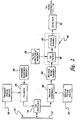
- FIG. 1 A conventional B-mode ultrasonic imaging system is depicted in FIG. 1.
- the system comprises a transducer array 10 comprising a plurality of separately driven transducer elements 12, each of which produces a burst of ultrasonic energy when energized by a pulsed waveform produced by a transmitter 14.
- the ultrasonic energy reflected back to transducer array 10 from the object under study is converted to an electrical signal by each receiving transducer element 12 and applied separately to a receiver 16 through a set of transmit/receive (T/R) switches 18.
- the T/R switches 18 are typically diodes which protect the receive electronics from the high voltages generated by the transmit electronics.
- the transmit signal causes the diodes to shut off or limit the signal to the receiver.
- Transmitter 14 and receiver 16 are operated under control of a master controller 20 responsive to commands by a human operator.
- a complete scan is performed by acquiring a series of echoes in which transmitter 14 is gated ON momentarily to energize each transducer element 12, and the subsequent echo signals produced by each transducer element 12 are applied to receiver 16.
- a channel may begin reception while another channel is still transmitting.
- Receiver 16 combines the separate echo signals from each transducer element to produce a single echo signal which is used to produce a line in an image on a display monitor 22.
- transmitter 14 drives transducer array 10 such that the ultrasonic energy is transmitted as a directed focused beam.
- respective time delays are imparted to a plurality of pulsers 24 by a transmit beamformer 26.
- Master controller 20 determines the conditions under which the acoustic pulses will be transmitted. With this information, transmit beamformer 26 determines the timing and amplitudes of each of the transmit pulses to be generated by pulsers 24. The amplitudes of each transmit pulse are generated by an apodization generation circuit 36, which may be a high-voltage controller that sets the power supply voltage to each pulser.
- Pulsers 24 in turn send the transmit pulses to each of elements 12 of transducer array 10 via T/R switches 18, which protect time-gain control (TGC) amplifiers 28 from the high voltages which may exist at the transducer array.
- Weightings are generated within apodization generation circuit 36, which may comprise a set of digital-to analog converters that take the weighting data from transmit beamformer 26 and apply it to pulsers 24.
- the echo signals produced by each burst of ultrasonic energy reflect from objects located at successive ranges along each transmit beam.
- the echo signals are sensed separately by each transducer element 12 and a sample of the magnitude of the echo signal at a particular point in time represents the amount of reflection occurring at a specific range. Due to differences in the propagation paths between a reflecting point and each transducer element 12, the echo signals will not be detected simultaneously and their amplitudes will not be equal.
- Receiver 16 amplifies the separate echo signals via a respective TGC amplifier 28 in each receive channel.
- the amount of amplification provided by the TGC amplifiers is controlled through a control path (not shown) that is driven by a TGC circuit (not shown), the latter being set by the master controller and hand operation of potentiometers.
- the amplified echo signals are then fed to a receive beamformer 30.
- Each receiver channel of the receive beamformer is coupled to a respective one of transducer elements 12 by a respective TGC amplifier 28.
- receive beamformer 30 tracks the direction of the transmitted beam.
- Receive beamformer 30 imparts the proper time delays and receive apodization weightings to each amplified echo signal and sums them to provide an echo signal which accurately indicates the total ultrasonic energy reflected from a point located at a particular range along one ultrasonic beam.
- the receive focus time delays are computed in real-time using specialized hardware or are read from a look-up table.
- the receive channels also have circuitry for filtering the received pulses.
- the time-delayed receive signals are then summed and supplied to a signal processor or detector 32. Detector 32 converts the summed receive signals to display data.
- a scan converter 34 receives the display data from detector 32 and converts the data into the desired image for display.
- scan converter 34 converts the acoustic image data from polar coordinate ( R ⁇ ) sector format or Cartesian coordinate linear array to appropriately scaled Cartesian coordinate display pixel data at the video rate.
- These scan-converted acoustic data are then provided for display on display monitor 22, which images the time-varying amplitude of the signal envelope as a grey scale. A respective scan line is displayed for each transmit beam.
- FIG. 2 shows an ultrasound B-mode flow imaging system in accordance with the present invention for use in medical diagnostics.
- each transducer element in the transmit aperture is pulsed N times using the same waveform by supplying transmit sequence 38 to each pulser N times.
- Pulsers 24 drive elements 12 of transducer array 10 such that the ultrasonic energy produced is directed or steered in a beam for each transmit firing.
- transmit focus time delays 36 are imparted to the respective pulsed waveforms produced by the pulsers in response to transmit sequence 38.
- the ultrasonic beam can be focused at a desired transmit focal position.
- the echo signals from transducer elements 12 are fed to respective receive channels 40 of the receive beamformer.
- the receive beamformer tracks the direction of the transmitted beam.
- the receive beamformer imparts the proper receive focus time delays 42 to the received echo signal and sums them to provide an echo signal which accurately indicates the total ultrasonic energy reflected from a particular position along a transmit beam.
- the time-delayed receive signals are summed in a receive summer 44 for each of the N transmit firings focused at a particular transmit focal position.
- the summed receive signals for successive transmit firings are provided to a wall filter 46, which filters across the N transmit firings and then supplies a filtered signal to detector 32.
- Detector 32 forms the envelope of the firing-to-firing filtered signal. After post-processing (including edge enhancement and logarithmic compression) and scan conversion, a scan line is displayed on display monitor 22 (FIG. 1). This procedure is repeated so that a respective scan line is displayed for each transmit focal position (in the case of one transmit focal position for each beam angle) or for each vector (in the case of multiple transmit focal positions for each beam angle).
- filter 46 comprises an FIR filter 48 having an input coupled to the output of receive summer 44; and a vector summer 50 having an input coupled to FIR filter 48 and an output coupled to detector 32.
- the FIR filter has M filter taps for receipt of a respective set of M filter coefficients for each transmit firing.
- the scalar weightings a 0 , a 1 , ..., a N -1 form a "wall" filter in slow time which selectively passes signals from reflectors moving at a velocity greater than a predetermined threshold.
- the filter coefficients a n c 0 , a n c 1 , ..., a n c M -1 are supplied to the filter for each transmit firing by the master controller from a filter coefficient memory 52.
- the set of filter coefficients a 0 c 0 , a 0 c 1 , ..., a 0 c M -1 is supplied to the FIR filter; for the second transmit firing, the set of filter coefficients a 1 c 0 , a 1 c 1 , ..., a 1 c M -1 is supplied to the FIR filter, and so forth.
- the filter coefficients are programmable depending upon the diagnostic application. Different sets of filter coefficients can be stored in look-up tables inside the master controller memory and the desired set of coefficients can be selectable by the system operator.
- pairs of sets of filter coefficients are stored in memory, one set of filter coefficients of a selected pair being transferred to the FIR filter before the first transmit firing and the other set of filter coefficients of the selected pair being transferred to the FIR filter after the first transmit firing and before the second transmit firing.
- two or three sets of filter coefficients are stored in memory for use in filtering the receive signals resulting from the first through third firings.
- a similar procedure is enacted for applications where the number of transmit firings N > 3.
- the successive FIR filter output signals for the N transmit firings are accumulated in a vector summer 50.
- the output signal of the vector summer then undergoes conventional B-mode processing, followed by scan conversion and display.
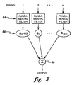
- a sequence of identical N broadband pulses, centered at a fundamental frequency, are transmitted by the transducer array to a particular transmit focal position.
- a bandpass filter centered at the fundamental frequency substantially isolates the desired fundamental component.
- a wall filter extracts the fundamental flow signal over the N transmits.
- a fundamental flow filter such as shown in FIG. 2 may comprise two stages: the first stage 54 extracts a major fraction of the fundamental component and the second stage 56 substantially suppresses the stationary fundamental components with a high-pass wall filter.
- Both stages of a fundamental flow filter are embodied in the FIR filter 48 shown in FIG. 2.
- a set of filter coefficients c 0 , c 1 , ..., c M -1 are selected so that the M -tap FIR filter 48 passes a major fraction of the fundamental frequencies in the receive signal.
- the wall filter weightings 56 which are a 0 , a 1 , ..., a N -1 are selected so that the fundamental signals are high-pass filtered across firings when the respective output signals of the FIR filter for a given transmit focal position are summed.
- the summed signal is then B-mode processed in conventional fashion, i.e., envelope detection, logarithmic compression, etc.
- the B-mode flow image is superimposed on a conventional B-mode image.
- This B-mode image feed-through is achieved by perturbing one of the wall filter weightings.
- the weighting a 0 for the first transmit firing can be perturbed by an amount ⁇ , as shown in the flow chart of FIG. 3.
- the B-mode feed-through allows the flow image to be superimposed on top of a conventional B-mode image for display.
- the flow image may be superimposed in color on top of a conventional B-mode image for display.
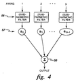
- contrast agents made up of gas-filled microbubbles are injected into the blood to serve as markers for imaging blood flow.
- multiple firings of identical pulses are transmitted to a particular transmit focal position in succession.
- N pulses centered at frequency f 0 are transmitted to each transmit focal position.
- a bandpass filter centered at a (sub)harmonic frequency substantially isolates the desired (sub)harmonic component.
- a wall filter extracts the (sub)harmonic flow signal over the N transmits.
- a (sub)harmonic flow filter may comprise two stages: a first stage 58 that extracts a major fraction of the (sub)harmonic component and a second stage 57 that substantially suppresses the stationary (sub)harmonic components with a high-pass wall filter.
- both filter stages are embodied in FIR filter 48 shown in FIG. 2.
- FIR filter 48 shown in FIG. 2.
- a set of (sub)harmonic filter coefficients c 0 , c 1 , ..., c M -1 are selected so that the M-tap FIR filter 48 passes a major fraction of the desired harmonic or subharmonic frequencies in the receive signal.
- the transmitted center frequency is at f 0 , then tissue/contrast nonlinearities will generate harmonics at kf 0 , where k is an integer greater than or equal to 2. Also, subharmonics at frequencies f 0 / k may be generated by contrast bubble destruction.
- the output signal of summer 50 is comprised of substantially only harmonic (or subharmonic) signals changing with time (i.e., moving reflectors).
- the second harmonic signal is imaged. This is accomplished using a conventional B-mode transmit sequence of identical pulses, except that the transmit signal needs to be more narrowband than usual to allow the second harmonic to also fit within the transducer bandwidth.
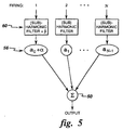
- FIG. 5 depicts feed-through of both the harmonic and B-mode (non-flow) image.
- the B-mode image feed-through is achieved by perturbing each of the coefficients c 0 , c 1 , ..., c M -1 of the (sub)harmonic filter stage 60 or portion of FIR filter 48 during one of the transmit firings by an amount ⁇ , causing the filter to pass fundamental B-mode signals.
- the B-mode feed-through allows some conventional B-mode image to pass such that the displayed image is a superposition of a harmonic flow image on a conventional B-mode image, the latter serving to provide familiar and recognizable image features to the sonographer.
- the harmonic feed-through does the same thing, except that it lets through a harmonic image instead of or in addition to a B-mode (fundamental) image.
- the harmonic images have been demonstrated to perform better than regular B-mode for certain difficult-to-image patients.
- the harmonic feed-through is achieved by perturbing one of the wall filter weightings a 0 , a 1 , ..., a N -1 .
- the weighting a 0 for the first transmit firing can be perturbed 56 by an amount ⁇ , as shown in FIG. 5.
- FIG. 5 depicts harmonic and B-mode feed-through during the same transmit firing, it will be appreciated that the harmonic and B-mode feed-throughs can be accomplished on different firings.
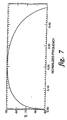
- the wall filter response as a function of normalized frequency for a wall filter having weightings [1, -1] is depicted in FIG. 6.
- the time interval between each of the N transmits per focal position is user controllable to determine the wall filter cut-off frequency. A longer interval between each of the N transmits to a particular focal position results in a lower cutoff frequency with higher sensitivity to low velocity flow.
Landscapes
- Engineering & Computer Science (AREA)
- Physics & Mathematics (AREA)
- Radar, Positioning & Navigation (AREA)
- Remote Sensing (AREA)
- Computer Networks & Wireless Communication (AREA)
- General Physics & Mathematics (AREA)
- Acoustics & Sound (AREA)
- Nonlinear Science (AREA)
- Ultra Sonic Daignosis Equipment (AREA)
- Closed-Circuit Television Systems (AREA)
- Image Analysis (AREA)
- Image Processing (AREA)
Applications Claiming Priority (4)
| Application Number | Priority Date | Filing Date | Title |
|---|---|---|---|
| US65212 | 1987-06-22 | ||
| US5278998A | 1998-03-31 | 1998-03-31 | |
| US52789 | 1998-03-31 | ||
| US09/065,212 US6074348A (en) | 1998-03-31 | 1998-04-23 | Method and apparatus for enhanced flow imaging in B-mode ultrasound |
Publications (3)
| Publication Number | Publication Date |
|---|---|
| EP0947853A2 EP0947853A2 (en) | 1999-10-06 |
| EP0947853A3 EP0947853A3 (en) | 2003-01-08 |
| EP0947853B1 true EP0947853B1 (en) | 2006-01-11 |
Family
ID=26731080
Family Applications (1)
| Application Number | Title | Priority Date | Filing Date |
|---|---|---|---|
| EP99302521A Expired - Lifetime EP0947853B1 (en) | 1998-03-31 | 1999-03-31 | Method and apparatus for enhanced flow imaging in b-mode ultrasound |
Country Status (5)
| Country | Link |
|---|---|
| US (2) | US6074348A (ja) |
| EP (1) | EP0947853B1 (ja) |
| JP (1) | JP4549457B2 (ja) |
| DE (1) | DE19913198A1 (ja) |
| IL (1) | IL129153A (ja) |
Cited By (1)
| Publication number | Priority date | Publication date | Assignee | Title |
|---|---|---|---|---|
| CN104902825B (zh) * | 2013-01-11 | 2016-11-09 | 株式会社日立制作所 | 超声波拍摄装置 |
Families Citing this family (50)
| Publication number | Priority date | Publication date | Assignee | Title |
|---|---|---|---|---|
| US6074348A (en) * | 1998-03-31 | 2000-06-13 | General Electric Company | Method and apparatus for enhanced flow imaging in B-mode ultrasound |
| US6210332B1 (en) * | 1998-03-31 | 2001-04-03 | General Electric Company | Method and apparatus for flow imaging using coded excitation |
| US6277075B1 (en) * | 1999-11-26 | 2001-08-21 | Ge Medical Systems Global Technology Company, Llc | Method and apparatus for visualization of motion in ultrasound flow imaging using continuous data acquisition |
| US6508766B2 (en) | 2000-01-20 | 2003-01-21 | Kabushiki Kaisha Toshiba | Ultrasound diagnostic apparatus |
| US6520915B1 (en) | 2000-01-28 | 2003-02-18 | U-Systems, Inc. | Ultrasound imaging system with intrinsic doppler capability |
| JP2001212144A (ja) * | 2000-01-31 | 2001-08-07 | Toshiba Corp | 超音波診断装置及び超音波画像化方法 |
| US7288069B2 (en) | 2000-02-07 | 2007-10-30 | Kabushiki Kaisha Toshiba | Ultrasonic probe and method of manufacturing the same |
| KR100350026B1 (ko) | 2000-06-17 | 2002-08-24 | 주식회사 메디슨 | 확산 대역 신호를 이용한 펄스 압축 방식에 기초한 초음파영상 형성 방법 및 장치 |
| US6318179B1 (en) * | 2000-06-20 | 2001-11-20 | Ge Medical Systems Global Technology Company, Llc | Ultrasound based quantitative motion measurement using speckle size estimation |
| US6866631B2 (en) * | 2001-05-31 | 2005-03-15 | Zonare Medical Systems, Inc. | System for phase inversion ultrasonic imaging |
| JP3959257B2 (ja) * | 2001-11-08 | 2007-08-15 | 株式会社東芝 | 超音波診断装置 |
| JP2003319939A (ja) | 2002-04-26 | 2003-11-11 | Ge Medical Systems Global Technology Co Llc | 超音波撮影装置 |
| US6796944B2 (en) | 2002-05-17 | 2004-09-28 | Ge Medical Systems Global Technology, Llc | Display for subtraction imaging techniques |
| US7092558B2 (en) | 2002-08-14 | 2006-08-15 | General Electric Company | Automated optimization of medical 3D visualizations |
| JP3964364B2 (ja) * | 2003-07-22 | 2007-08-22 | ジーイー・メディカル・システムズ・グローバル・テクノロジー・カンパニー・エルエルシー | 超音波診断装置 |
| EP1515158B1 (en) * | 2003-09-09 | 2013-07-17 | Esaote S.p.A. | Ultrasound imaging method combined with the presence of contrast media in the body under examination |
| WO2005024462A1 (en) * | 2003-09-10 | 2005-03-17 | Koninklijke Philips Electronics, N.V. | Ultrasonic spatial compounding with multiple simultaneous beam transmission |
| WO2005070299A1 (en) * | 2004-01-16 | 2005-08-04 | The University Of Houston System | Methods and apparatus for medical imaging |
| JP2008532608A (ja) * | 2005-03-11 | 2008-08-21 | コーニンクレッカ フィリップス エレクトロニクス エヌ ヴィ | 3次元超音波潅流画像のボリュームレンダリングシステム及び方法 |
| US20080021945A1 (en) * | 2006-07-20 | 2008-01-24 | James Hamilton | Method of processing spatial-temporal data processing |
| US20100138191A1 (en) * | 2006-07-20 | 2010-06-03 | James Hamilton | Method and system for acquiring and transforming ultrasound data |
| US20080021319A1 (en) * | 2006-07-20 | 2008-01-24 | James Hamilton | Method of modifying data acquisition parameters of an ultrasound device |
| WO2008016992A1 (en) * | 2006-08-01 | 2008-02-07 | Scimed Life Systems, Inc. | Pulse inversion sequences for nonlinear imaging |
| US9295444B2 (en) | 2006-11-10 | 2016-03-29 | Siemens Medical Solutions Usa, Inc. | Transducer array imaging system |
| US8499634B2 (en) * | 2006-11-10 | 2013-08-06 | Siemens Medical Solutions Usa, Inc. | Transducer array imaging system |
| US20080114247A1 (en) * | 2006-11-10 | 2008-05-15 | Penrith Corporation | Transducer array imaging system |
| US8490489B2 (en) * | 2006-11-10 | 2013-07-23 | Siemens Medical Solutions Usa, Inc. | Transducer array imaging system |
| US7984651B2 (en) * | 2006-11-10 | 2011-07-26 | Penrith Corporation | Transducer array imaging system |
| US8600299B2 (en) * | 2006-11-10 | 2013-12-03 | Siemens Medical Solutions Usa, Inc. | Transducer array imaging system |
| US8312771B2 (en) * | 2006-11-10 | 2012-11-20 | Siemens Medical Solutions Usa, Inc. | Transducer array imaging system |
| CN101662988B (zh) * | 2007-04-24 | 2011-08-03 | 松下电器产业株式会社 | 超声波诊断装置 |
| US20100185085A1 (en) * | 2009-01-19 | 2010-07-22 | James Hamilton | Dynamic ultrasound processing using object motion calculation |
| US20100086187A1 (en) * | 2008-09-23 | 2010-04-08 | James Hamilton | System and method for flexible rate processing of ultrasound data |
| JP5263867B2 (ja) * | 2007-10-15 | 2013-08-14 | ジーイー・メディカル・システムズ・グローバル・テクノロジー・カンパニー・エルエルシー | 超音波撮像装置 |
| JP5555416B2 (ja) * | 2007-10-25 | 2014-07-23 | 三星メディソン株式会社 | 超音波診断装置及びスキャンラインデータ形成方法 |
| KR100930073B1 (ko) * | 2007-11-13 | 2009-12-08 | 서강대학교산학협력단 | 제2 고조파 신호 검출 장치 및 그 방법 |
| WO2010083468A1 (en) * | 2009-01-19 | 2010-07-22 | Ultrasound Medical Devices, Inc. | System and method for acquiring and processing partial 3d ultrasound data |
| KR101175421B1 (ko) * | 2009-12-14 | 2012-08-20 | 삼성메디슨 주식회사 | 적응형 클러터 필터링 방법 및 그를 위한 초음파 시스템 |
| WO2011133171A1 (en) * | 2010-04-23 | 2011-10-27 | Ultrasound Medical Devices, Inc. | Method for measuring image motion with synthetic speckle patterns |
| JP5570877B2 (ja) | 2010-06-04 | 2014-08-13 | 株式会社東芝 | 超音波診断装置 |
| CN102728007B (zh) * | 2011-03-29 | 2015-07-08 | 重庆微海软件开发有限公司 | 超声治疗系统的控制系统 |
| JP2013094223A (ja) * | 2011-10-28 | 2013-05-20 | Ge Medical Systems Global Technology Co Llc | 超音波診断装置 |
| CN103126725B (zh) * | 2011-12-01 | 2015-05-13 | 深圳迈瑞生物医疗电子股份有限公司 | 一种超声成像的方法和装置 |
| KR101390187B1 (ko) * | 2011-12-28 | 2014-04-29 | 삼성메디슨 주식회사 | 파티클 플로우 영상을 제공하는 초음파 시스템 및 방법 |
| DE102012212894A1 (de) * | 2012-07-24 | 2014-01-30 | Robert Bosch Gmbh | Verfahren zum Betrieb eines Umfelderfassungssystems eines Fahrzeugs mit zumindest zwei Sende-/Empfangseinheiten und Umfelderfassungssystem |
| GB2515073B (en) | 2013-06-13 | 2017-12-13 | Gen Electric | Imaging or analysis of flowing media |
| US11026655B2 (en) * | 2014-09-26 | 2021-06-08 | Samsung Electronics Co., Ltd. | Ultrasound diagnostic apparatus and method of generating B-flow ultrasound image with single transmission and reception event |
| WO2017035838A1 (zh) * | 2015-09-06 | 2017-03-09 | 深圳迈瑞生物医疗电子股份有限公司 | 超声灰阶成像系统及方法 |
| US20190117195A1 (en) * | 2016-03-21 | 2019-04-25 | Analogic Canada Corporation | Visualization of Ultrasound Vector Flow Imaging (VFI) Data |
| CN114002846B (zh) * | 2021-10-28 | 2024-01-19 | 中国兵器工业集团第二一四研究所苏州研发中心 | 一种基于emccd的微光成像辅助驾驶系统 |
Family Cites Families (20)
| Publication number | Priority date | Publication date | Assignee | Title |
|---|---|---|---|---|
| US4276885A (en) * | 1979-05-04 | 1981-07-07 | Rasor Associates, Inc | Ultrasonic image enhancement |
| DE3829999A1 (de) * | 1988-09-01 | 1990-03-15 | Schering Ag | Ultraschallverfahren und schaltungen zu deren durchfuehrung |
| JPH0523334A (ja) * | 1991-07-25 | 1993-02-02 | Matsushita Electric Ind Co Ltd | 超音波ドプラ映像装置 |
| US5453575A (en) * | 1993-02-01 | 1995-09-26 | Endosonics Corporation | Apparatus and method for detecting blood flow in intravascular ultrasonic imaging |
| US5445156A (en) * | 1994-11-02 | 1995-08-29 | General Electric Company | Method for adaptively filtering doppler signals using a complex time domain filter |
| US5456257A (en) * | 1994-11-23 | 1995-10-10 | Advanced Technology Laboratories, Inc. | Ultrasonic detection of contrast agents |
| US5724976A (en) * | 1994-12-28 | 1998-03-10 | Kabushiki Kaisha Toshiba | Ultrasound imaging preferable to ultrasound contrast echography |
| EP0770352B1 (en) * | 1995-10-10 | 2004-12-29 | Advanced Technology Laboratories, Inc. | Ultrasonic diagnostic imaging with contrast agents |
| US5706819A (en) * | 1995-10-10 | 1998-01-13 | Advanced Technology Laboratories, Inc. | Ultrasonic diagnostic imaging with harmonic contrast agents |
| JP3580627B2 (ja) * | 1996-01-29 | 2004-10-27 | 株式会社東芝 | 超音波診断装置 |
| JPH1028685A (ja) * | 1996-07-18 | 1998-02-03 | Ge Yokogawa Medical Syst Ltd | 超音波イメージング方法及び装置並びに超音波造影剤及びその製造方法 |
| JP3746119B2 (ja) * | 1996-10-25 | 2006-02-15 | 株式会社東芝 | 超音波診断装置 |
| JP4382884B2 (ja) * | 1996-11-08 | 2009-12-16 | コーニンクレッカ フィリップス エレクトロニクス エヌ ヴィ | 高調波による超音波画像処理方法および装置 |
| EP0851241B1 (en) * | 1996-11-26 | 2006-05-24 | ATL Ultrasound, Inc. | Ultrasonic diagnostic imaging of response frequency differing from transmit frequency |
| US5921931A (en) * | 1997-04-08 | 1999-07-13 | Endosonics Corporation | Method and apparatus for creating a color blood flow image based upon ultrasonic echo signals received by an intravascular ultrasound imaging probe |
| US5882306A (en) * | 1997-04-11 | 1999-03-16 | Acuson Corporation | Ultrasound imaging methods and systems |
| US5882315A (en) * | 1997-12-23 | 1999-03-16 | Acuson Corporation | Ultrasonic imaging method and image for doppler tissue parameters |
| US6074348A (en) * | 1998-03-31 | 2000-06-13 | General Electric Company | Method and apparatus for enhanced flow imaging in B-mode ultrasound |
| US6210332B1 (en) * | 1998-03-31 | 2001-04-03 | General Electric Company | Method and apparatus for flow imaging using coded excitation |
| US6190321B1 (en) * | 1999-08-06 | 2001-02-20 | Acuson Corporation | Medical diagnostic ultrasound imaging methods for estimating motion between composite ultrasonic images and recovering color doppler values from composite images |
-
1998
- 1998-04-23 US US09/065,212 patent/US6074348A/en not_active Expired - Lifetime
-
1999
- 1999-03-24 IL IL12915399A patent/IL129153A/xx not_active IP Right Cessation
- 1999-03-24 DE DE19913198A patent/DE19913198A1/de not_active Withdrawn
- 1999-03-31 JP JP09041099A patent/JP4549457B2/ja not_active Expired - Fee Related
- 1999-03-31 EP EP99302521A patent/EP0947853B1/en not_active Expired - Lifetime
-
2000
- 2000-04-24 US US09/557,255 patent/US6406430B1/en not_active Expired - Fee Related
Cited By (1)
| Publication number | Priority date | Publication date | Assignee | Title |
|---|---|---|---|---|
| CN104902825B (zh) * | 2013-01-11 | 2016-11-09 | 株式会社日立制作所 | 超声波拍摄装置 |
Also Published As
| Publication number | Publication date |
|---|---|
| JP4549457B2 (ja) | 2010-09-22 |
| JPH11318902A (ja) | 1999-11-24 |
| EP0947853A3 (en) | 2003-01-08 |
| US6074348A (en) | 2000-06-13 |
| EP0947853A2 (en) | 1999-10-06 |
| IL129153A (en) | 2003-02-12 |
| US6406430B1 (en) | 2002-06-18 |
| DE19913198A1 (de) | 1999-10-07 |
| IL129153A0 (en) | 2000-02-17 |
Similar Documents
| Publication | Publication Date | Title |
|---|---|---|
| EP0947853B1 (en) | Method and apparatus for enhanced flow imaging in b-mode ultrasound | |
| EP0948931B1 (en) | Ultrasound imaging using coded excitation on transmit and selective filtering on receive | |
| US6210332B1 (en) | Method and apparatus for flow imaging using coded excitation | |
| US6312384B1 (en) | Method and apparatus for flow imaging using golay codes | |
| US6108572A (en) | Method and apparatus for harmonic imaging using multiple focal zones | |
| US6796944B2 (en) | Display for subtraction imaging techniques | |
| US5961463A (en) | Nonlinear imaging using orthogonal transmit and receive codes | |
| EP1501419B1 (en) | Contrast-agent enhanced color-flow imaging | |
| US5014710A (en) | Steered linear color doppler imaging | |
| US6186950B1 (en) | Ultrasonic pulse inversion harmonic separation with reduced motional effects | |
| US6171246B1 (en) | Realtime ultrasonic imaging of perfusion using ultrasonic contrast agents | |
| US6210335B1 (en) | Acoustic flash to increase penetration | |
| US5165413A (en) | Steered linear color doppler imaging | |
| US6267725B1 (en) | Individual channel analog wall filtering to improve flow sensitivity in ultrasound imaging | |
| JP2004195228A (ja) | 最適化された送信シーケンスを用いた超音波撮像における適応フィルタリング | |
| JPH03155843A (ja) | 超音波診断装置 | |
| US6478741B2 (en) | Transmission of optimized pulse waveforms for ultrasonic subharmonic imaging | |
| JPH03261466A (ja) | 超音波診断装置 | |
| JP4746758B2 (ja) | Bモード及びカラー・フロー・モードでの強化された流れ撮像を結合することによる超音波画像表示 |
Legal Events
| Date | Code | Title | Description |
|---|---|---|---|
| PUAI | Public reference made under article 153(3) epc to a published international application that has entered the european phase |
Free format text: ORIGINAL CODE: 0009012 |
|
| AK | Designated contracting states |
Kind code of ref document: A2 Designated state(s): AT BE CH CY DE DK ES FI FR GB GR IE IT LI LU MC NL PT SE |
|
| AX | Request for extension of the european patent |
Free format text: AL;LT;LV;MK;RO;SI |
|
| PUAL | Search report despatched |
Free format text: ORIGINAL CODE: 0009013 |
|
| AK | Designated contracting states |
Kind code of ref document: A3 Designated state(s): AT BE CH CY DE DK ES FI FR GB GR IE IT LI LU MC NL PT SE |
|
| AX | Request for extension of the european patent |
Free format text: AL;LT;LV;MK;RO;SI |
|
| 17P | Request for examination filed |
Effective date: 20030708 |
|
| AKX | Designation fees paid |
Designated state(s): NL |
|
| 17Q | First examination report despatched |
Effective date: 20030814 |
|
| REG | Reference to a national code |
Ref country code: DE Ref legal event code: 8566 |
|
| GRAP | Despatch of communication of intention to grant a patent |
Free format text: ORIGINAL CODE: EPIDOSNIGR1 |
|
| GRAS | Grant fee paid |
Free format text: ORIGINAL CODE: EPIDOSNIGR3 |
|
| GRAA | (expected) grant |
Free format text: ORIGINAL CODE: 0009210 |
|
| AK | Designated contracting states |
Kind code of ref document: B1 Designated state(s): NL |
|
| PLBE | No opposition filed within time limit |
Free format text: ORIGINAL CODE: 0009261 |
|
| STAA | Information on the status of an ep patent application or granted ep patent |
Free format text: STATUS: NO OPPOSITION FILED WITHIN TIME LIMIT |
|
| 26N | No opposition filed |
Effective date: 20061012 |
|
| PGFP | Annual fee paid to national office [announced via postgrant information from national office to epo] |
Ref country code: NL Payment date: 20080324 Year of fee payment: 10 |
|
| NLV4 | Nl: lapsed or anulled due to non-payment of the annual fee |
Effective date: 20091001 |
|
| PG25 | Lapsed in a contracting state [announced via postgrant information from national office to epo] |
Ref country code: NL Free format text: LAPSE BECAUSE OF NON-PAYMENT OF DUE FEES Effective date: 20091001 |