EP0947265A2 - Verfahren zum Stranggiessen und Fertigwalzen eines Giessstranges innerhalb einer vorgegebenen Fertigbreitentoleranz - Google Patents
Verfahren zum Stranggiessen und Fertigwalzen eines Giessstranges innerhalb einer vorgegebenen Fertigbreitentoleranz Download PDFInfo
- Publication number
- EP0947265A2 EP0947265A2 EP99106087A EP99106087A EP0947265A2 EP 0947265 A2 EP0947265 A2 EP 0947265A2 EP 99106087 A EP99106087 A EP 99106087A EP 99106087 A EP99106087 A EP 99106087A EP 0947265 A2 EP0947265 A2 EP 0947265A2
- Authority
- EP
- European Patent Office
- Prior art keywords
- width
- actuators
- slab
- mold
- finishing train
- Prior art date
- Legal status (The legal status is an assumption and is not a legal conclusion. Google has not performed a legal analysis and makes no representation as to the accuracy of the status listed.)
- Granted
Links
Images


Classifications
-
- B—PERFORMING OPERATIONS; TRANSPORTING
- B22—CASTING; POWDER METALLURGY
- B22D—CASTING OF METALS; CASTING OF OTHER SUBSTANCES BY THE SAME PROCESSES OR DEVICES
- B22D11/00—Continuous casting of metals, i.e. casting in indefinite lengths
- B22D11/16—Controlling or regulating processes or operations
-
- B—PERFORMING OPERATIONS; TRANSPORTING
- B22—CASTING; POWDER METALLURGY
- B22D—CASTING OF METALS; CASTING OF OTHER SUBSTANCES BY THE SAME PROCESSES OR DEVICES
- B22D11/00—Continuous casting of metals, i.e. casting in indefinite lengths
- B22D11/12—Accessories for subsequent treating or working cast stock in situ
- B22D11/1206—Accessories for subsequent treating or working cast stock in situ for plastic shaping of strands
-
- Y—GENERAL TAGGING OF NEW TECHNOLOGICAL DEVELOPMENTS; GENERAL TAGGING OF CROSS-SECTIONAL TECHNOLOGIES SPANNING OVER SEVERAL SECTIONS OF THE IPC; TECHNICAL SUBJECTS COVERED BY FORMER USPC CROSS-REFERENCE ART COLLECTIONS [XRACs] AND DIGESTS
- Y10—TECHNICAL SUBJECTS COVERED BY FORMER USPC
- Y10T—TECHNICAL SUBJECTS COVERED BY FORMER US CLASSIFICATION
- Y10T29/00—Metal working
- Y10T29/49—Method of mechanical manufacture
- Y10T29/49764—Method of mechanical manufacture with testing or indicating
-
- Y—GENERAL TAGGING OF NEW TECHNOLOGICAL DEVELOPMENTS; GENERAL TAGGING OF CROSS-SECTIONAL TECHNOLOGIES SPANNING OVER SEVERAL SECTIONS OF THE IPC; TECHNICAL SUBJECTS COVERED BY FORMER USPC CROSS-REFERENCE ART COLLECTIONS [XRACs] AND DIGESTS
- Y10—TECHNICAL SUBJECTS COVERED BY FORMER USPC
- Y10T—TECHNICAL SUBJECTS COVERED BY FORMER US CLASSIFICATION
- Y10T29/00—Metal working
- Y10T29/49—Method of mechanical manufacture
- Y10T29/4998—Combined manufacture including applying or shaping of fluent material
- Y10T29/49988—Metal casting
- Y10T29/49991—Combined with rolling
Definitions
- the invention relates to a method for continuous casting and finish rolling a casting slab within a specified finished width tolerance, where for the casting slab and occasionally a follow-up slab Adjustment of the mold position, in particular according to different ones Rolling conditions is made.
- Slabs enable continuous casting with continuous casting formats between about 30 and 100 mm thickness at 800 to 2200 mm width and a preferred direct rolling with compared to conventional production processes significantly reduced forming work in a rolling mill, the production chain from raw steel to rolled product is significantly shortened.
- the device shows a corresponding prior art EP-OS 0 149 734.
- This document is a Mold for the continuous casting of thin slabs with cooled broad side walls and narrow side walls, the wide side walls only one funnel-shaped, restricted to part of the mold height Form the pouring area to the narrow sides and in the pouring direction is reduced to the size of the cast slab.
- the broad side walls to the side of the funnel-shaped pouring area a distance parallel to the slab thickness up to that respective narrow side wall to form a respective from the pouring area outgoing parallel area.
- the narrow side walls are adjustable in the parallel area of the broad side walls. The adjustment e.g. the width of thin slabs is also from DE 35 01 422 C2 known.
- the present invention is based on the aforementioned prior art the task is based on a method in the preamble of claim 1 mentioned type to develop in continuous cast and rolled thin slabs adhering to narrow width tolerances when To be able to keep finished tape.
- the actuators relieved the finishing train and through the finishing width Presetting of the mold slab started for slab.
- An embodiment of the method provides that the actuators the mold in accordance with the calculated TARGET setting be approached before casting the subsequent slabs, and that the Calculating the finishing train actuators using a pass schedule model Contour model and a spreading model are used, and before the subsequent slabs are rolled, the TARGET setting determined by the invoice the finishing train actuators are approached.
- finishing train actuators be used for the width adjustment.
- the effective parameters of the finishing train are used for the width, that the desired (often the same) finished bandwidth within the tolerance arises (see explanations for Fig. 3).
- One embodiment of the method provides that the width is preset for the mold actuators and the finishing train actuators (Preset) is made in such a way that for each rolled strip approximately the middle of the tolerance band of the finished width.
- the production control system according to the invention is advantageous achieved that a width preset on the mold is made and at the same time the adjustment ranges in the Rolling mill can be withdrawn.
- the method according to the invention provides that by Comparison of the measured width of the slab with the calculated one Slab width an adaptation correction coefficient obtained and to Correction of the spreading model is used.
- a width error measured in the caster area can also affect the Spreading model of the finishing train can be activated.
- the procedure provides for enlargement the tolerance range for the setting of the mold position the minimum / maximum setting ranges of the finishing train sections be determined so that only after reaching minimum or maximum Adjustment ranges of the finishing train actuators a change in Chill position is made.
- the diagram lines in the upper area of FIG. 1 show a pass schedule with a larger number of coils, the thicknesses of the Products of individual coils vary between 1 and 3 mm.
- the lower diagram lines show that when the Position of the mold there are considerably different bandwidths to adjust.
- the hatched areas under the bandwidth line indicate the excess widths that occur when the rolled strip is thin on. From this it can be seen that as the thickness of a rolled one increases Band whose spread decreases disproportionately.
- the result is Conclusion that a calculation of the necessary for each finished strip Mold width must be carried out, for the associated instantly cast slab or for the present slab. Width adjustment of the mold from slab to slab is required like this from the dependence between strip thickness and Spread from the diagrams of Fig. 1 can be read in order with the Width of a strip rolled out, for example, to a strip thickness of 1 mm within the tolerance range Tol, i.e. under the hatched area lie.
- the finishing train actuators to use for the width adjustment.
- the frequency of the adjustment of the mold adjustment elements to minimize or avoid their adjustment, the Effective parameters ( ⁇ W) of the finishing train are used so that the desired Finished bandwidth within the specified tolerance is observed.
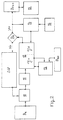
- the maximum permitted strip dimensions of a planned production program are considered and the effective parameters ( ⁇ W) of the finishing train are used in the direction of spreading or constriction. If the input width (B BR ) is present, then according to the flow diagram according to FIG. 2, the finishing line effective parameters ( ⁇ W) for the bandwidth are used for fine tuning in accordance with the claimed ranking so that the difference between the calculated finished tape width and the target width is below Consideration of the plant and material limits is minimized.
- the width of the rolled strip is checked to see whether it is within the permissible range. If so, the optimization measures are not iterated. If not, then the finishing train parameters are changed iteratively, ie step by step. After the change has been defined, the finished road setting consisting of stitch plan model 10, contour model 11 and widening model 12 is triggered again, both for the width change (12a) on the caster C and for the width change (12b) in the Finishing line F. This iteration loop is called up until the options for changing the finishing line operating parameters ⁇ W have been exhausted.
- the designation B F1-n denotes the bandwidths between the individual stands of the finishing train.
- the flow chart also shows that an adaptation value 13 is obtained by comparing the measured width of the casting slab B BR with the calculated slab width (12a).
- the measured bandwidth 16 is also used for a correction value in comparison to the calculated bandwidth 14 and is applied to the spreading model 12.
- FIG. 3 shows the procedure for determining the optimum Mold width with the goal for the planned production spectrum to select the same mold positions as possible in a rolling program, shown.
- the dashed lines show finished strip widths Standard driving style, i.e. without mold width optimization and without Use of the finishing train actuators.
- the thick solid lines show finished strip widths with mold width optimization and with Use of the finishing train actuators.
- the mold width B K is selected so that the width B F2 for the finished product 2 lies in the hatched tolerance window or is equal to the target width B Z , then over-widths B F1 often result for the finished product 1 with the same mold width.
- the effective width ranges W 1 , W 2 of the finishing train actuators for both finished products 2 and 1 are determined.
- the mean value B M between the maximum possible finished width B F2 and the minimum possible finished width B F1 is determined.
Landscapes
- Engineering & Computer Science (AREA)
- Mechanical Engineering (AREA)
- Continuous Casting (AREA)
- Metal Rolling (AREA)
- Control Of Metal Rolling (AREA)
Abstract
Description
- daß zur Erzielung der vorgegebenen Fertigbreite innerhalb eines Toleranzbandes zunächst eine Voreinstellung der Kokillenposition unter anderem unter Berücksichtigung der extremen Bandabmessungen des geplanten Produktionsprogramms vorgenommen und
- für jede Gießbramme und fallweise eine Folgebramme eine Berechnung für den optimalen Einsatz der Kokillenstellglieder und der Stellglieder der Fertigstraße vorgenommen, und
- daß bei vorliegender Eingangsbreite der Gießbramme in die Fertigstraße eine Nachoptimierung der Fertigbreite mit Hilfe der Stellglieder der Fertigstraße vorgenommen wird.
- daß vor der Produktion einer neuen Gießbramme eine Band-Kontur-Berechnung und eine Stichplanberechnung sowie das Breitungsmodell angestoßen werden, wonach
- ein entsprechendes Preset der Kokillen-Stellglieder vorgenommen wird,
- anschließend die effektive Breite des fertig gewalzten Bandes gemessen, und
- das Ergebnis einer fallweise erforderlichen Korrektur des Breitungsmodells und damit der Berechnung der Fertigstraßen-Stellglieder zugrunde gelegt wird.
- Breitenänderung zwischen Kokille und Caster austritt
- Temperaturschrumpf vom Caster bis zum Fertigband
- Bandzüge innerhalb der Fertigstraße
- Konturänderungen der Brammenform bis hin zur Fertigbandform
- Planheitszustand des Bandes zwischen den Fertiggerüsten
- natürliche Breitung des Bandes, Dicke des Bandes
- Walzgeschwindigkeit, Walztemperatur
- Materialqualität des Bandes
- Stauchabnahme
- Brammen- bzw. Vorbandkontur (als Meß- oder Rechenwert).
- Änderung der Abnahmeverteilung in der Straße
- Änderung des Zielprofils im Rahmen des Profiltoleranzbandes
- Änderung der Zugspannung zwischen den Gerüsten
- Einsatz eines Stauchers
- Änderung der aktiven Gerüstzahl oder der Stichanzahl.
- Figur 1
- ein Walzprogramm mit einer Anzahl Coils unterschiedlicher Banddicke und daraus resultierender unterschiedlicher Fertigbreite bei konstant eingestellter Kokillenposition (dargestellt anhand einer bekannten CSP-Anlage);
- Figur 2
- ein Berechnungsmodell zur Bestimmung und zum Fine-Tuning der Bandbreite;
- Figur 3
- Diagramme gleicher Kokillenbreite für unterschiedliche Fertigprodukte mit und ohne Optimierungsverfahren.
- dF(mm)
- = Fertigbanddicke
- ΔBF(mm)
- = Breitenabweichung
- Tol
- = max. Toleranzbreite des Walzbandes
- BFSoll
- = SOLL-Fertigbreite des Walzbandes
- Ww
- = Walzenwechsel
- BK
- = Kokillenbreite/Vorbandbreite (Kopf/Ende)
- BF
- = eff. Fertigbreite des Walzbandes
- BF1-n
- = Bandbreiten zwischen den Gerüsten
- BBR
- = gemessene Brammenbreite
- ΔW
- = Änderung der Fertigstraßen-Wirkparameter
- 10
- = Stichplan-Modell
- 11
- = Kontur-Modell
- 12
- = Breitungs-Modell (C = Caster;
F = Fertigstraße) - 13
- = Adaption Casterbreite
- 14
- = Adaption Bandbreite
- 15
- = Position Seitenführungen
- 16
- = gemessene Fertigbreite des Walzbandes
- BK1; BK2
- = Kokillenbreite ohne Optimierung
- BKopt
- = Kokillenbreite mit Optimierung
- W1; W2
- = Wirkglieder-Stellbereich der Fertigstraße
- St
- = Einfluß der Stellglieder
- BF1; BF2
- = Fertigbandbreiten ohne Optimierung
- B'F1; B'F2
- = Fertigbandbreiten mit Optimierung
- BZ
- = Zielbreite
- ΔB
- = Breitentoleranz des Walzbandes
- ΔBopt
- = Breitendifferenz der Kokille zwischen den Positionen mit und ohne Optimierung
- BM
- = Mittelwert zwischen max. möglicher Fertig breite BF2 und min. möglicher Fertigbreite BF1
- Index 1
- = Fertigprodukt 1
- Index 2
- = Fertigprodukt 2
- Stichplanmodell (10)
- Konturmodell (11)
- Breitungsmodell (12)
- Algorithmus zur Veränderung von Fertigstraßenwirkparametern ΔW in beanspruchter Rangfolge
- dF(mm)
- = Fertigbanddicke
- ΔBF(mm)
- = Breitenabweichung
- Tol
- = max. Toleranzbreite des Walzbandes
- BFSoll
- = SOLL-Fertigbreite des Walzbandes
- Ww
- = Walzenwechsel
- BK
- = Kokillenbreite/Vorbandbreite (Kopf/Ende)
- BF
- = eff. Fertigbreite des Walzbandes
- BF1-n
- = Bandbreiten zwischen den Gerüsten
- BBR
- = gemessene Brammenbreite
- ΔW
- = Änderung der Fertigstraßen-Wirkparameter
- 10
- = Stichplan-Modell
- 11
- = Kontur-Modell
- 12
- = Breitungs-Modell (c = Caster;
F = Fertigstraße) - 13
- = Adaption Casterbreite
- 14
- = Adaption Bandbreite
- 15
- = Position Seitenführungen
- 16
- = gemessene Fertigbreite des Walzbandes
- BK1; BK2
- = Kokillenbreite ohne Optimierung
- BKopt
- = Kokillenbreite mit Optimierung
- W1; W2
- = Wirkglieder-Stellbereich der Fertigstraße
- St
- = Stellglieder
- BF1; BF2
- = Fertigbandbreiten ohne Optimierung
- B'F1; B'F2
- = Fertigbandbreiten mit Optimierung
- BZ
- = Zielbreite
- ΔB
- = Breitentoleranz des Walzbandes
- ΔBopt
- = Breitendifferenz der Kokille zwischen den Positionen mit und ohne Optimierung
- BM
- = Mittelwert zwischen max. möglicher Fertig breite BF2 und min. möglicher Fertigbreite BF1
- Index 1
- = Fertigprodukt 1
- Index 2
- = Fertigprodukt 2
Claims (12)
- Verfahren zum Stranggießen und Fertigwalzen einer gegossenen Bramme innerhalb einer vorgegebenen Fertigbreitentoleranz des Walzbandes, wobei für die Gießbramme und fallweise eine Folgebramme eine Einstellung der Kokillenposition insbesondere nach Maßgabe unterschiedlicher Walzbedingungen vorgenommen wird,
dadurch gekennzeichne,daß zur Erzielung der vorgegebenen Fertigbreite (Bz) des Walzbandes innerhalb eines Toleranzbandes (ΔB) zunächst eine Voreinstellung der Kokillenposition (BK) unter anderem unter Berücksichtigung der extremen Bandabmessungen des geplanten Produktionsprogramms vorgenommen, undfür jede Gießbramme und fallweise eine Folgebramme eine Berechnung für den optimalen Einsatz der Kokillenstellglieder und der Stellglieder der Fertigstraße vorgenommen wird, und
daß bei vorliegender Eingangsbreite der Gießbramme in die Fertigstraße eine Nachoptimierung der Fertigbreite des Walzbandes mit Hilfe der Stellglieder der Fertigstraße vorgenommen wird. - Verfahren nach Anspruch 1,
dadurch gekennzeichnet,
daß die Stellglieder der Kokille entsprechend der rechnerisch ermittelten SOLL-Einstellung vor dem Gießen der Folgebramme angefahren werden, und daß der Berechnung der Kokillen-Stellglieder und/oder der Fertigstraßen-Stellglieder ein Stichplanmodell (10), ein Konturmodell (11) und ein Breitungsmodell (12) zugrunde gelegt werden, und vor dem Walzen der Folgebramme die durch Rechnung ermittelte SOLL-Einstellung der Fertigstraßen-Stellglieder angefahren wird. - Verfahren nach Anspruch 1 oder 2,
dadurch gekennzeichnet,
daß die Breitenvoreinstellung für die Kokillenstellglieder und die Fertigstraßenstellglieder (Preset) so vorgenommen wird, daß sich für jedes Walzband etwa die Mitte des Toleranzbandes (ΔB) der Fertigbreite des Walzbandes ergibt. - Verfahren nach einem oder mehreren der Ansprüche 1 bis 3,
dadurch gekennzeichnet,daß vor der Produktion einer neuen Gießbramme eine Band-Kontur-Berechnung und eine Stichplanberechnung sowie das Breitungsmodell angestoßen werden, wonachein entsprechendes Preset der Kokillenstellglieder vorgenommen,anschließend die effektive Breite (BF) des fertig gewalzten Bandes gemessen, unddas Ergebnis einer fallweise erforderlichen Korrektur des Breitungsmodells und damit der Berechnung der Fertigstraßen-Stellglieder zugrunde gelegt wird. - Verfahren nach einem oder mehreren der Ansprüche 1 bis 4,
dadurch gekennzeichnet,
daß nach Maßgabe einer erforderlichen Korrekturgröße des Preset bevorzugt bei unveränderter Kokillenposition zunächst die Fertigstraßen-Stellglieder geändert werden. - Verfahren nach einem oder mehreren der Ansprüche 1 bis 5,
dadurch gekennzeichnet,
daß für einen optimalen Einsatz der Stellglieder für Kokille und Fertigstraße zur Erzielung hoher Genauigkeit ein Breitungsmodell (12) als Grundlage für eine Preset-Einstellung verwendet wird, das wenigstens die folgenden Einflüsse berücksichtigt:Breitenänderung zwischen Kokille und CasteraustrittTemperaturschrumpf vom Caster bis zum FertigbandBandzüge innerhalb der FertigstraßeKonturäßderungen der Brammenform bis hin zur FertigbandformPlanheitszustand des Bandes zwischen den FertiggerüstenBanddicke, natürliche Breitung des BandesWalzgeschwindigkeit, WalztemperaturMaterialqualität des BandesStauchabnahmeBrammen- bzw. Vorbandkontur (als Meß- oder Rechenwert) - Verfahren nach einem oder mehreren der Ansprüche 1 bis 6,
dadurch gekennzeichnet,
daß durch Vergleich der gemessenen Breite (BBR) der Gießbramme mit der errechneten Brammenbreite ein Adaptions-Korrekturkoeffizient (13) gewonnen und zur Korrektur des Breitungsmodelles (12a) verwendet wird. - Verfahren nach einem oder mehreren der Ansprüche 1 bis 7,
dadurch gekennzeichnet,
daß ein im Casterbereich gemessener Breitenfehler auf das Breitungsmodell der Fertigstraße (12b) aufgeschaltet wird. - Verfahren nach einem oder mehreren der Ansprüche 1 bis 8,
dadurch gekennzeichnet,
daß zum Fine-Tuning der Fertigbreite des Walzbandes in der Fertigstraße die folgenden Wirkparameter (ΔW) in der angegebenen Rangfolge berücksichtigt und derart eingesetzt werden, daß die Differenz zwischen der errechneten Breite und der Zielbreite minimiert wird:Änderung der Abnahmeverteilung in der FertigstraßeÄnderung des Zielprofils im Rahmen des ProfiltoleranzbandesÄnderung der Zugspannung zwischen den GerüstenEinsatz eines StauchersÄnderung der aktiven Gerüstzahl oder der Stichzahl. - Verfahren nach einem oder mehreren der Ansprüche 1 bis 9,
dadurch gekennzeichnet,
daß zur Erweiterung des Toleranzbereiches für die Einstellung der Kokillenposition die minimalen/maximalen Stellbereiche der Fertigstraßenstellglieder ermittelt werden. - Verfahren nach einem oder mehreren der Ansprüche 1 bis 10,
dadurch gekennzeichnet,
daß die Stellglieder der Kokille und/oder die Stellglieder für die Breitenbeeinflussung in der Fertigstraße statisch bzw. über die Bandlänge veränderbar eingesetzt werden. - Anwendung des Verfahrens nach mindestens einem der Ansprüche 1 bis 11auf mindestens eine Dünnbrammengießmaschine mit mindestens einer unmittelbar nachgeschalteten, insbesondere mehrgerüstigen Walzstraße,auf konventionelle, insbesondere mehrgerüstige Fertigstraßen,auf Walzstraßen mit einem Reversiergerüst, insbesondere mit mehreren Stichen arbeitend,auf das Walzen von Endlosbändern,auf das Walzen von Einzelbändern.
Applications Claiming Priority (2)
| Application Number | Priority Date | Filing Date | Title |
|---|---|---|---|
| DE19814222A DE19814222A1 (de) | 1998-03-31 | 1998-03-31 | Verfahren zum Stranggießen und Fertigwalzen eines Gießstranges innerhalb einer vorgegebenen Fertigbreitentoleranz |
| DE19814222 | 1998-03-31 |
Publications (3)
| Publication Number | Publication Date |
|---|---|
| EP0947265A2 true EP0947265A2 (de) | 1999-10-06 |
| EP0947265A3 EP0947265A3 (de) | 2001-01-31 |
| EP0947265B1 EP0947265B1 (de) | 2005-09-28 |
Family
ID=7862993
Family Applications (1)
| Application Number | Title | Priority Date | Filing Date |
|---|---|---|---|
| EP99106087A Expired - Lifetime EP0947265B1 (de) | 1998-03-31 | 1999-03-26 | Verfahren zum Stranggiessen und Fertigwalzen eines Giessstranges innerhalb einer vorgegebenen Fertigbreitentoleranz |
Country Status (6)
| Country | Link |
|---|---|
| US (1) | US6112394A (de) |
| EP (1) | EP0947265B1 (de) |
| JP (1) | JPH11319901A (de) |
| AT (1) | ATE305347T1 (de) |
| DE (2) | DE19814222A1 (de) |
| ES (1) | ES2249855T3 (de) |
Cited By (1)
| Publication number | Priority date | Publication date | Assignee | Title |
|---|---|---|---|---|
| EP3173166A1 (de) * | 2015-11-26 | 2017-05-31 | SMS group GmbH | Verfahren und vorrichtung zum einstellen der breite eines stranggegossenen metallstrangs |
Families Citing this family (4)
| Publication number | Priority date | Publication date | Assignee | Title |
|---|---|---|---|---|
| DE10047381A1 (de) * | 2000-09-25 | 2002-04-18 | Siemens Ag | Verfahren und Vorrichtung zum Betreiben einer Anlage der Grundstoffindustrie |
| US6857464B2 (en) | 2002-09-19 | 2005-02-22 | Hatch Associates Ltd. | Adjustable casting mold |
| CN101786146B (zh) * | 2009-12-30 | 2012-01-11 | 东北大学 | 一种在线控制炼钢连铸的方法 |
| RU2453385C2 (ru) * | 2010-08-30 | 2012-06-20 | Закрытое акционерное общество "Волгоградский металлургический завод "Красный Октябрь" (ЗАО "ВМЗ "Красный Октябрь") | Способ прокатки с созданием заданного напряженного состояния по сечению заготовки и заготовка для его осуществления |
Family Cites Families (12)
| Publication number | Priority date | Publication date | Assignee | Title |
|---|---|---|---|---|
| US3358358A (en) * | 1964-12-31 | 1967-12-19 | United States Steel Corp | Method of reducing width of metal slabs |
| JPS5340631A (en) * | 1976-09-27 | 1978-04-13 | Kawasaki Steel Co | Method of changing width of casting in continuous casting |
| US4110824A (en) * | 1977-05-18 | 1978-08-29 | Youngstown Sheet And Tube Company | Method and apparatus for continuously processing strand |
| US4577277A (en) * | 1983-03-07 | 1986-03-18 | Kabushiki Kaisha Kobe Seiko Sho | Method and apparatus of continuous casting by the use of mold oscillating system |
| DE3400220A1 (de) * | 1984-01-05 | 1985-07-18 | SMS Schloemann-Siemag AG, 4000 Düsseldorf | Kokille zum stranggiessen von stahlband |
| AT379093B (de) * | 1984-02-16 | 1985-11-11 | Voest Alpine Ag | Durchlaufkokille fuer eine stranggiessanlage |
| JPS63252609A (ja) * | 1987-04-10 | 1988-10-19 | Mitsubishi Heavy Ind Ltd | ホツトストリツプミルの板幅制御方法 |
| JPH01233005A (ja) * | 1988-03-14 | 1989-09-18 | Sumitomo Metal Ind Ltd | 薄鋳片の熱間圧延における板幅制御方法 |
| US5205345A (en) * | 1991-08-07 | 1993-04-27 | Acutus Industries | Method and apparatus for slab width control |
| JP2698520B2 (ja) * | 1992-08-31 | 1998-01-19 | 日立金属株式会社 | 通気性鋳型の鋳造方案の作成方法 |
| DE4310332A1 (de) * | 1993-03-31 | 1994-10-06 | Mueller Weingarten Maschf | Verfahren zur Ermittlung von optimalen Parametern eines Gießprozesses insbesondere an Druckgießmaschinen |
| JPH08192209A (ja) * | 1995-01-13 | 1996-07-30 | Kobe Steel Ltd | ストリップの熱間圧延方法 |
-
1998
- 1998-03-31 DE DE19814222A patent/DE19814222A1/de not_active Withdrawn
-
1999
- 1999-03-26 DE DE59912593T patent/DE59912593D1/de not_active Expired - Lifetime
- 1999-03-26 EP EP99106087A patent/EP0947265B1/de not_active Expired - Lifetime
- 1999-03-26 AT AT99106087T patent/ATE305347T1/de active
- 1999-03-26 ES ES99106087T patent/ES2249855T3/es not_active Expired - Lifetime
- 1999-03-30 US US09/281,486 patent/US6112394A/en not_active Expired - Lifetime
- 1999-03-31 JP JP11091945A patent/JPH11319901A/ja active Pending
Cited By (1)
| Publication number | Priority date | Publication date | Assignee | Title |
|---|---|---|---|---|
| EP3173166A1 (de) * | 2015-11-26 | 2017-05-31 | SMS group GmbH | Verfahren und vorrichtung zum einstellen der breite eines stranggegossenen metallstrangs |
Also Published As
| Publication number | Publication date |
|---|---|
| JPH11319901A (ja) | 1999-11-24 |
| ES2249855T3 (es) | 2006-04-01 |
| US6112394A (en) | 2000-09-05 |
| EP0947265A3 (de) | 2001-01-31 |
| ATE305347T1 (de) | 2005-10-15 |
| DE19814222A1 (de) | 1999-10-07 |
| DE59912593D1 (de) | 2005-11-03 |
| EP0947265B1 (de) | 2005-09-28 |
Similar Documents
| Publication | Publication Date | Title |
|---|---|---|
| EP1799368B1 (de) | Verfahren und vorrichtung zum kontinuierlichen herstellen eines dünnen metallbandes | |
| DE69211869T2 (de) | Verfahren zum Walzen von Stahlprofilen | |
| EP1519798B1 (de) | Verfahren und giesswalzanlage zum semi-endloswalzen oder endloswalzen durch giessen eines metalls insbesondere eines stahlstrangs, der nach dem erstarren bei bedarf quergeteilt wird | |
| EP0121148B1 (de) | Verfahren zum Herstellen von Walzband mit hoher Bandprofil- und Bandplanheitsgüte | |
| DE19654068A1 (de) | Verfahren und Vorrichtung zum Walzen eines Walzbandes | |
| DE60016999T2 (de) | Verfahren und Vorrichtung zum Regeln der Bandform beim Bandwalzen | |
| DE69104169T2 (de) | Verfahren zur Regelung der Kantenabsenkung beim Kaltwalzen von Stahl. | |
| DE19644132B4 (de) | Verfahren zum Optimieren der Bandbreitenverteilung an den Enden eines eine Walzstraße durchlaufenden Bandes | |
| DE3522631C2 (de) | ||
| EP1330321A1 (de) | Verfahren und vorrichtung zum stranggiessen und anschliessendem verformen eines giessstranges aus stahl, insbesondere eines giessstranges mit blockformat oder vorprofil-format | |
| EP2906369B1 (de) | Breitenbeeinflussung eines bandförmigen walzguts | |
| DE4009861C2 (de) | Verfahren zur Herstellung von warmgewalztem Stangenmaterial wie Feinstahl oder Draht und Anlage zur Durchführung des Verfahrens | |
| EP0947265A2 (de) | Verfahren zum Stranggiessen und Fertigwalzen eines Giessstranges innerhalb einer vorgegebenen Fertigbreitentoleranz | |
| EP1035928A1 (de) | Verfahren und einrichtung zum walzen eines walzbandes mit variierender dicke | |
| EP0734793A1 (de) | Verfahren und Vorrichtung zur Herstellung von warmgewalztem Stahlband | |
| WO2022017690A1 (de) | Giess-walz-verbundanlage zur herstellung eines warmgewalzten fertigbands aus einer stahlschmelze | |
| EP4247574A1 (de) | VERFAHREN ZUR EINSTELLUNG DER EIGENSCHAFTEN EINES WARMBANDES MIT EINER BESTIMMTEN CHEMISCHEN ZUSAMMENSETZUNG IN EINER WARMBANDSTRAßE | |
| EP0811435A2 (de) | Voreinstellung für Kaltwalzreversiergerüst | |
| DE3401894A1 (de) | Verfahren zum herstellen von walzband mit hoher bandprofil- und bandplanheitsguete | |
| DE60113132T2 (de) | Blechbreitenregelung beim warmbandwalzen | |
| DE19704337A1 (de) | Verfahren und Einrichtung zur Verlaufsregelung eines Walzbandes | |
| DE19644131C2 (de) | Verfahren zum Optimieren der Bandbreitenverteilung an den Enden eines eine Walzstraße in einem oder mehreren Stichen durchlaufenden Bandes | |
| DE19900779B4 (de) | Verfahren zum Walzen von Metallband und Anlage zur Durchführung des Verfahrens | |
| DE10159608B4 (de) | Walzverfahren für ein Band mit einer Schweißnaht | |
| EP0936002B1 (de) | Walzverfahren für ein Band, insbesondere ein Metallband |
Legal Events
| Date | Code | Title | Description |
|---|---|---|---|
| PUAI | Public reference made under article 153(3) epc to a published international application that has entered the european phase |
Free format text: ORIGINAL CODE: 0009012 |
|
| 17P | Request for examination filed |
Effective date: 19990326 |
|
| AK | Designated contracting states |
Kind code of ref document: A2 Designated state(s): AT BE CH CY DE DK ES LI |
|
| AX | Request for extension of the european patent |
Free format text: AL;LT;LV;MK;RO;SI |
|
| RTI1 | Title (correction) |
Free format text: PROCESS FOR CONTINUOUS CASTING AND FINISH ROLLING OF A CAST STRAND WITHIN A PREDETERMINED NET WIDTH |
|
| RAP1 | Party data changed (applicant data changed or rights of an application transferred) |
Owner name: SMS DEMAG AG |
|
| PUAL | Search report despatched |
Free format text: ORIGINAL CODE: 0009013 |
|
| AK | Designated contracting states |
Kind code of ref document: A3 Designated state(s): AT BE CH CY DE DK ES FI FR GB GR IE IT LI LU MC NL PT SE |
|
| AX | Request for extension of the european patent |
Free format text: AL;LT;LV;MK;RO;SI |
|
| AKX | Designation fees paid |
Free format text: AT BE CH CY DE DK ES LI |
|
| RBV | Designated contracting states (corrected) |
Designated state(s): AT DE ES FR GB IT NL |
|
| 17Q | First examination report despatched |
Effective date: 20021104 |
|
| APBR | Date of receipt of statement of grounds of appeal recorded |
Free format text: ORIGINAL CODE: EPIDOSNNOA3E |
|
| APBX | Invitation to file observations in appeal sent |
Free format text: ORIGINAL CODE: EPIDOSNOBA2E |
|
| APBZ | Receipt of observations in appeal recorded |
Free format text: ORIGINAL CODE: EPIDOSNOBA4E |
|
| APBT | Appeal procedure closed |
Free format text: ORIGINAL CODE: EPIDOSNNOA9E |
|
| GRAP | Despatch of communication of intention to grant a patent |
Free format text: ORIGINAL CODE: EPIDOSNIGR1 |
|
| APAA | Appeal reference recorded |
Free format text: ORIGINAL CODE: EPIDOS REFN |
|
| GRAS | Grant fee paid |
Free format text: ORIGINAL CODE: EPIDOSNIGR3 |
|
| GRAA | (expected) grant |
Free format text: ORIGINAL CODE: 0009210 |
|
| AK | Designated contracting states |
Kind code of ref document: B1 Designated state(s): AT DE ES FR GB IT NL |
|
| REG | Reference to a national code |
Ref country code: GB Ref legal event code: FG4D Free format text: NOT ENGLISH |
|
| APAH | Appeal reference modified |
Free format text: ORIGINAL CODE: EPIDOSCREFNO |
|
| REF | Corresponds to: |
Ref document number: 59912593 Country of ref document: DE Date of ref document: 20051103 Kind code of ref document: P |
|
| GBT | Gb: translation of ep patent filed (gb section 77(6)(a)/1977) |
Effective date: 20060108 |
|
| REG | Reference to a national code |
Ref country code: ES Ref legal event code: FG2A Ref document number: 2249855 Country of ref document: ES Kind code of ref document: T3 |
|
| ET | Fr: translation filed | ||
| PLBE | No opposition filed within time limit |
Free format text: ORIGINAL CODE: 0009261 |
|
| STAA | Information on the status of an ep patent application or granted ep patent |
Free format text: STATUS: NO OPPOSITION FILED WITHIN TIME LIMIT |
|
| 26N | No opposition filed |
Effective date: 20060629 |
|
| REG | Reference to a national code |
Ref country code: DE Ref legal event code: R082 Ref document number: 59912593 Country of ref document: DE Representative=s name: HEMMERICH & KOLLEGEN, DE Ref country code: DE Ref legal event code: R081 Ref document number: 59912593 Country of ref document: DE Owner name: SMS GROUP GMBH, DE Free format text: FORMER OWNER: SMS SIEMAG AKTIENGESELLSCHAFT, 40237 DUESSELDORF, DE |
|
| REG | Reference to a national code |
Ref country code: FR Ref legal event code: PLFP Year of fee payment: 18 |
|
| REG | Reference to a national code |
Ref country code: FR Ref legal event code: PLFP Year of fee payment: 19 |
|
| REG | Reference to a national code |
Ref country code: FR Ref legal event code: PLFP Year of fee payment: 20 |
|
| PGFP | Annual fee paid to national office [announced via postgrant information from national office to epo] |
Ref country code: DE Payment date: 20180322 Year of fee payment: 20 Ref country code: GB Payment date: 20180321 Year of fee payment: 20 Ref country code: NL Payment date: 20180321 Year of fee payment: 20 |
|
| PGFP | Annual fee paid to national office [announced via postgrant information from national office to epo] |
Ref country code: AT Payment date: 20180322 Year of fee payment: 20 Ref country code: FR Payment date: 20180323 Year of fee payment: 20 |
|
| PGFP | Annual fee paid to national office [announced via postgrant information from national office to epo] |
Ref country code: ES Payment date: 20180427 Year of fee payment: 20 |
|
| PGFP | Annual fee paid to national office [announced via postgrant information from national office to epo] |
Ref country code: IT Payment date: 20180327 Year of fee payment: 20 |
|
| REG | Reference to a national code |
Ref country code: DE Ref legal event code: R071 Ref document number: 59912593 Country of ref document: DE |
|
| REG | Reference to a national code |
Ref country code: NL Ref legal event code: MK Effective date: 20190325 |
|
| REG | Reference to a national code |
Ref country code: GB Ref legal event code: PE20 Expiry date: 20190325 |
|
| PG25 | Lapsed in a contracting state [announced via postgrant information from national office to epo] |
Ref country code: GB Free format text: LAPSE BECAUSE OF EXPIRATION OF PROTECTION Effective date: 20190325 |
|
| REG | Reference to a national code |
Ref country code: AT Ref legal event code: MK07 Ref document number: 305347 Country of ref document: AT Kind code of ref document: T Effective date: 20190326 |
|
| REG | Reference to a national code |
Ref country code: ES Ref legal event code: FD2A Effective date: 20220104 |
|
| PG25 | Lapsed in a contracting state [announced via postgrant information from national office to epo] |
Ref country code: ES Free format text: LAPSE BECAUSE OF EXPIRATION OF PROTECTION Effective date: 20190327 |