EP0946072B1 - Verfahren und system zur vermeidung von, in einem zellularen system durch nachbarfrequenzen verursachten interferenzen, durch die auswahl zwischen nachbarfrequenzen und anderen frequenzen - Google Patents
Verfahren und system zur vermeidung von, in einem zellularen system durch nachbarfrequenzen verursachten interferenzen, durch die auswahl zwischen nachbarfrequenzen und anderen frequenzen Download PDFInfo
- Publication number
- EP0946072B1 EP0946072B1 EP99105138.4A EP99105138A EP0946072B1 EP 0946072 B1 EP0946072 B1 EP 0946072B1 EP 99105138 A EP99105138 A EP 99105138A EP 0946072 B1 EP0946072 B1 EP 0946072B1
- Authority
- EP
- European Patent Office
- Prior art keywords
- carrier frequency
- cellular system
- mobile station
- base station
- adjacent
- Prior art date
- Legal status (The legal status is an assumption and is not a legal conclusion. Google has not performed a legal analysis and makes no representation as to the accuracy of the status listed.)
- Expired - Lifetime
Links
- 230000001413 cellular effect Effects 0.000 title claims description 322
- 238000000034 method Methods 0.000 title claims description 88
- 241000269799 Perca fluviatilis Species 0.000 claims description 117
- 238000004891 communication Methods 0.000 claims description 109
- 230000005540 biological transmission Effects 0.000 claims description 81
- 230000008859 change Effects 0.000 claims description 45
- 238000005259 measurement Methods 0.000 claims description 21
- 230000001629 suppression Effects 0.000 claims description 12
- 230000007480 spreading Effects 0.000 description 4
- 238000013459 approach Methods 0.000 description 3
- 230000003247 decreasing effect Effects 0.000 description 3
- 230000001747 exhibiting effect Effects 0.000 description 3
- 230000004044 response Effects 0.000 description 3
- 238000010586 diagram Methods 0.000 description 2
- 230000002238 attenuated effect Effects 0.000 description 1
- 230000015556 catabolic process Effects 0.000 description 1
- 238000010276 construction Methods 0.000 description 1
- 238000006731 degradation reaction Methods 0.000 description 1
- 230000001419 dependent effect Effects 0.000 description 1
- 230000002542 deteriorative effect Effects 0.000 description 1
- 238000012544 monitoring process Methods 0.000 description 1
- 230000005855 radiation Effects 0.000 description 1
- 230000009467 reduction Effects 0.000 description 1
- 230000002747 voluntary effect Effects 0.000 description 1
Images






Classifications
-
- H—ELECTRICITY
- H04—ELECTRIC COMMUNICATION TECHNIQUE
- H04W—WIRELESS COMMUNICATION NETWORKS
- H04W72/00—Local resource management
- H04W72/50—Allocation or scheduling criteria for wireless resources
- H04W72/54—Allocation or scheduling criteria for wireless resources based on quality criteria
- H04W72/541—Allocation or scheduling criteria for wireless resources based on quality criteria using the level of interference
-
- H—ELECTRICITY
- H04—ELECTRIC COMMUNICATION TECHNIQUE
- H04W—WIRELESS COMMUNICATION NETWORKS
- H04W16/00—Network planning, e.g. coverage or traffic planning tools; Network deployment, e.g. resource partitioning or cells structures
- H04W16/14—Spectrum sharing arrangements between different networks
Definitions
- the present invention relates to a method of preventing interference of adjacent frequencies in a cellular system, and more particularly to a method of preventing interference of adjacent frequencies in a cellular system that may be caused by adjacent carrier frequencies for uplink channels used by the independent cellular systems.
- a specified frequency band is allocated to a cellular system, and a plurality of carrier frequencies which different frequencies are predetermined within this frequency band.
- a mobile station establishes a channel between itself and a base station in an service area using the carrier frequencies to perform two-way communication therebetween.
- the base station and the mobile station are designed so as to control leakage power into frequency bands adjacent to both sides of the used carrier frequency as little as possible. However, the leakage power can not be fully suppressed, so that an interference signal power is supplied to a signal of an adjacent frequency at predetermined rate.
- each of the mobile stations establishes a channel between itself and the base station closest to it to perform communication.
- an uplink channel which is a channel established from a mobile station to a base station
- the transmission power of the uplink channel for transmitting a signal from the mobile station to the base station is controlled such that the difference between received powers of the signals from the mobile station, received by the base station may not be large. For this reason, an interference signal power supplied from a signal of an adjacent frequency becomes smaller than a desired signal power.
- a downlink channel which is a channel established from a base station to a mobile station
- an interference signal power from signals transmitted on a frequency adjacent to that of a desired wave signal reaches the mobile station through the same transmission path to be attenuated similarly. Accordingly, the interference signal power from the signal having a frequency adjacent to that of the desired wave signal is smaller than the desired signal power.
- such interference of adjacent frequencies may not pose a serious problem.
- the interference of adjacent frequencies may pose a serious problem when another cellular system having an allocated frequency band adjacent to the frequency band of the particular cellular system establishes a base station in the same service area and communicates with a mobile station.
- a mobile station 221 located near base station 261 belonging to the other cellular system establishes a channel and communicates with base station 211, it sends a signal with a power sufficiently large for reception to base station 211 remote from mobile station 221, so that the signal is also received with a large power by base station 261.
- mobile station 271 establishing a channel with base station 261 controls the transmission power so that the received power is not too large at base station 261, only the received signal from mobile station 221 may be exceedingly large.
- One of solutions to such a problem is to make an interval between carrier frequencies used in different cellular systems wider than that between the carrier frequencies used in the same cellular system. Because the spacing between the carrier frequencies among the cellular systems becomes wider, this solution is disadvantageous in reducing utilization efficiency of frequency bands. However, in a cellular system using many narrow band signals, the spacing between the carrier frequencies small as compared with the total of the frequency band, so that the reduction in the utilization efficiency is not so serious. On the other hand, in a cellular system in which a small number of wide band signals in the same frequency band are used, the spacing between the frequency bands is large as compared with the total of the frequency bands, thus significantly reducing the utilization efficiency.
- a transmitter in the mobile station since a transmitter in the mobile station has typically a simpler construction as compared with the base station, it has sometimes a low suppression of a leakage power into an adjacent carrier frequency. Therefore, when a certain mobile station is located near a base station belonging to another cellular system and the mobile station performs a transmission using adjacent carrier frequencies for an uplink channel as well as for a downlink channel, the mobile station is able to continue the communication with a good quality without being applied with an interference of adjacent frequencies because of a low leakage power from transmitting signals of the base station to the adjacent carrier frequency. However, because of a large leakage power from transmitting signals from the mobile station to an adjacent carrier frequency. A mobile station may cause an one-sided interference obstacle to the base station.
- Document WO 98/09466 A discloses an allocation method and system for allocating a least-interfered communications link between a cellular mobile station and a private radio base station within a cellular system.
- a set of candidate carrier frequencies are first selected and ordered by the amount of interference present within the cellular system, and a subset thereof selected.
- a second set of candidate frequencies are then selected from the subset, and in a second embodiment, a second set of candidate frequencies and associated timeslots are selected.
- the candidates are then ordered by the amount of interference present in the private radio system environment, and a second subset thereof selected.
- that channel exhibiting the least amount of interference is then selected from the safe channel subset as the communications link channel.
- a plurality of discrete hop lists for each timeslot are then formed, and one of the hop lists exhibiting the least amount of interference is then selected to be applied in the communications link.
- the method of preventing an interference of adjacent frequencies in a cellular system is used for preventing an interference to a base station of another cellular system from a signal of an uplink channel used by a mobile station of one cellular system.
- transmitters of base stations and mobile stations in all of embodiments described below are configured such that a ratio of an interference signal power leaking from a carrier frequency to a carrier frequency adjacent thereto to a radiation power of the carrier frequency may be below a predetermined value.
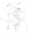
- a cellular system according to a first embodiment of the present invention.
- cellular system A there are two cellular systems, referred to as cellular system A, cellular system B, respectively.
- Cellular system A comprised base stations 11-13 in each service area, and a mobile station 11.
- Mobile station is positioned within the service area of base station 11.
- Each base stations 11-13 is connected a control station (not shown), which in turn connected to a communication network (not shown).
- cellular system A comprises in addition to base stations a number of bases stations (not shown) and a number of mobile station (not shown) in each service area.
- cellular system B comprises base station 61-63 in each service area, a mobile station, and control stations.
- Cellular system B also comprises additional bases station and additional mobile stations.
- Cellular system A and cellular B are connected each other via than associated networks.
- These two cellular systems A, B employ a CDMA method as a radio access method. Wherein a different code is allocated for each channel to multiplex a plurality of channels on one signal, thus enabling communications with one signal between plural base stations and plural mobile stations.
- Ga1 to Ga3 carrier frequencies Fa1 to Fa3 are allocated to cellular system A as signals for uplink channel and downlink channel, respectively, while, carrier frequencies Fb1 to Fb3, Gb1 to G3 are allocated to cellular system B as signals for the uplink channel and downlink channel, respectively.
- Carrier frequency Fa3 of the uplink channel in cellular system A is adjacent to carrier frequency Fb1 of the uplink channel in cellular system B
- carrier frequency Ga3 of the downlink channel in cellular system A is adjacent to carrier frequency Gb1 of downlink channel in cellular system B.
- Each of the cellular systems is designed in such manner part or all of the frequencies allocated thereto are used in the respective base stations.
- Base stations 11 to 13 and base stations 61 to 63 transmit a perch channel in each of the signals the downlink channels that are being used by the respective base stations.
- a perch channel is a channel which serves to transmit various kinds of base station information for connecting a channel from the base station to the mobile station.
- the mobile station first acquires the base station information from the perch channel when connecting a channel with the base station.
- the transmission power on ordinary channel varies, whereas transmission power on a perch channel is invariable. The power of this perch channel is large compared to that of an ordinary channel.
- Fig. 2 only perch channel 31 transmitted from base station 11 and perch channel 81 transmitted from base station 61 are illustrated, and perch channels transmitted from base stations 12 and 13 and base stations 62 and 63 are omitted.
- Each of mobile stations 21 and 71 include a measurement instrument (not shown) for measuring a received power of the perch channel.
- Mobile station 21 measures the received power of the perch channel of the base station in cellular system A, which is around mobile station 21, including perch channel 31, and mobile station 71 measures the received power of the perch channel of the base station in cellular system B which is around mobile station 71, including perch channel 81. Further, mobile station 21 measures the received power of the transmitting signal of the base stations in cellular system B, and mobile station 71 measures the received power of the transmitting signal of the base stations in cellular system A. At this time, by measuring the received power of the perch channel, each of mobile stations 21 and 71 measures the received power of the transmitting signal of the base stations.
- Mobile stations 21 and 71 usually receive the communication channel for the downlink channel continuously. However, when there is an idle-time in the transmission of the downlink channel, the mobile stations 21 and 71 intermittently receive the communication channel of the downlink channel.
- mobile station 21 When mobile station 21 intermittently receives communication channel 41, mobile station 21 measures the received power of the perch channel of base stations 61 to 63 in cellular system B using the idle-time when the communication channel is not received,. Mobile station 71 also measures the received power of the perch channel of base stations 11 to 13 in cellular system A using the idle-time similarly.
- Each of the mobile stations switches over the measurement instruments for the measurement of the received power of the perch channel for a short period of time in unit of slot as shown in Fig. 4 , to measure the received down the perch channels of the plural base stations once for each frame.
- the mobile station Since one frame of 10 ms is composed of six slots in the example shown in Fig. 4 , it is possible to perform the measurement for up to six base stations. Thus, the mobile station measures the plural perch channels concurrently.
- the instantaneous value of the received power of the perch channel varies in a short cycle with time as shown in Fig. 5 .
- a mobile station measures a received power for the frames by the number corresponding to a sufficiently long time as compared with the cycle the variation in the instantaneous value of the received power at the time the mobile station moves, and obtains the median of the measurement value in these slots.
- a mobile station When starting perform communication, a mobile station establish a channel between itself and a base station whose median of the received power of the perch channel is at a maximum. During the communication, with the movement of the mobile station, the received power of the perch channel varies. When the base station Whose median of the received power of the perch channel is at a maximum is ranged others, the mobile station performs an inter-base station handover for changing a base station in which a channel is to be established.
- Each of base stations 11 to 13 and 61 to 63 includes a measurement instrument (not shown) for measuring a ratio of a desired signal power of an uplink channel to an interference signal power of the uplink channel (hereinafter referred to as a SIR: Signal Interference Ratio).
- the base station measures the SIR upon each receipt of a slot of communication channel of the uplink channel.
- the base station informs control command to increase power when the SIR measured every slot is smaller than a target value, and a control command to decrease power.
- the SIR is larger than the target value.
- the mobile station controls the transmission power based on the control command transmitted from the base station in which a line is established with the mobile station.
- the SIR of the signal transmitted from the mobile station in which a channel is established with the base station will be close to the target value.
- carrier frequencies Fa1 to Fa3 of the uplink channel and carrier frequencies Ga1 to Ga3 of the downlink channel are set for each of base stations 11 to 13. Further, carrier frequencies Fb1 to Fb3 of the uplink channel and carrier frequencies Gb1 to Gb3 of the downlink channel are set for each of base stations 61 to 63.
- Base stations 11 to 13 of cellular system A obtain information concerning central frequencies of carrier frequencies Fb1 to Fb3 of the downlink channel used by cellular system B, as well as information concerning codes used in perch channels through a communication network to which a control station in cellular system B is connected.
- the code refers to a spreading code used at the time of spreading modulation.
- the information is conveyed to mobile station 21 using the perch channels of carrier frequencies Ga1 to Ga3 of the downlink channel.
- mobile station 21 can get carrier frequencies Ga1 to Ga3 of the downlink channel used by base stations 61 to 63 of cellular system B and the spreading code used in the transmitted perch channel.
- Mobile station 21 can measure the received power of the perch channel transmitted from each of base stations 61 to 63 using the information of spreading code and the carrier frequencies.
- the mobile station can receive the perch channel if it searches only for the informed code. Therefore, the mobile station is able to easily receive the perch channel. In this manner, the mobile station measures also the received power of the perch channel transmitted by the base station of another cellular system.
- Mobile station 21 establishes a channel with base station 11. A transmission from base station 11 to mobile station 21 is performed on communication channel 41 of the downlink channel, while a transmission from mobile station 21 to base station 11 is performed on communication channel 51 of the uplink channel.
- mobile station 71 it is assumed that the received power of perch channel 81 among the perch channels transmitted by the base station of cellular system B is at a maximum.
- Mobile station 71 establishes communication channel 91 of the downlink channel and communication channel 101 of the uplink channel together with base station 61, and performs communication with base station 61.
- mobile station 21 of cellular system A measures the perch channels of base stations 61 to 63 of cellular system B. The received power of the perch channel of base station 61 among these perch channels is assumed to maximum.
- step 701 when a request for communication with base station 11 is made, mobile station 21 measures received power Qp2 of the perch channel of base station 61 in cellular system B.
- step 702 mobile station 21 determines whether or not the measured received power Qp2 is larger than threshold Qth1. If the measured received power Qp2 is larger than threshold Qth1, in step 702 then mobile station 21 requests a carrier frequency which is not adjacent to carrier frequencies (hereinafter referred to as a non-adjacent carrier frequency) Fb1 to Fb3 in cellular system B from base station 11 in step 703. That, in step 705, base station 11 decides to allocate either non-adjacent carrier frequency Fa1 or non-adjacent carrier frequency Fa2, which is not adjacent to carrier frequency Fb1 as a signal of the uplink channel and informs allocation of mobile station 21.
- a carrier frequency which is not adjacent to carrier frequencies (hereinafter referred to as a non-adjacent carrier frequency) Fb1 to Fb3 in cellular system B from base station 11 in
- step 702 mobile station 21 requests a carrier frequency Fa3 adjacent to either the non-adjacent carrier frequency or carrier frequency Fb1 of cellular system B from base station 11 in step 704.
- the request for the allocation of either the non-adjacent carrier frequency or the adjacent carrier frequency means a request for a selection of voluntary frequency.
- step 705 base station 11 decides the allocation for a signal of the uplink channel from among carrier frequencies Fa1 to Fa3, and informs the allocation to mobile station 21.
- base station 11 decides the carrier frequency to be allocated based on the request from mobile station 21 to inform it to mobile station 21.
- Mobile station 21 receives the allocation report.
- step 706 mobile station 21 starts communication using the carrier frequency received from base station 11.
- step 707 even during the communication, mobile station 21 measures received power Qp2 of the perch channel of base station 61 to 63 in cellular system B.
- step 708 mobile station 21 determines whether or not the received power Qp2 of the perch channel of base station 61 closest to the mobile station 21 is larger than threshold Qth1, base station 61 exhibiting the largest received power: If it is determined that received power Qp2 is larger than threshold Qth1 in step 708, than mobile station 21 determines whether or not adjacent carrier frequency Fa3 is in use in step 709.
- mobile station 21 requests the allocation of non-adjacent carrier frequencies from base station 11 in step 710.
- base station 11 Upon receipt of the allocation request of the non-adjacent carrier frequency transmitted from mobile station 21, base station 11 decides the allocation of a signal of the uplink channel from carrier frequencies Fa1 and Fa2, and informs mobile station 21 of the allocation.
- mobile station 21 determines whether or not the non-adjacent carrier frequency is in use in step 711. If the non-adjacent carrier frequency is in use in step 711, mobile station 21 informs base station 11 that the adjacent carrier frequency is available, in step 712. Upon receipt of the information, base station 11 compares the load of the carrier frequency now in use with the load of the adjacent carrier frequency. If the load of the carrier frequency now in use is larger than the load of the adjacent carrier frequency, base station 11 changes the carrier frequency to adjacent carrier frequency Fa3.
- a case where the load of the carrier frequency now in use is larger than the load of the adjacent carrier frequency refers to, for example, a case where the number of the mobile stations using the carrier frequency now in use is close to line capacitance limitation and the number of the mobile stations using adjacent carrier frequency Fa3 is small.
- base station 11 informs mobile station 21 of the result of the carrier frequency change.
- step 713 mobile station 21 determines whether or not mobile station 21 has received the notice of the carrier frequency change from base station 11. If mobile station 21 has received the notice of the carrier frequency change, then mobile station 21 changes the carrier frequency now in use to the carrier frequency reported in step 714. Then, mobile station 21 determines whether or not the communication has been terminated in step 715. If the communication has been terminated, mobile station 21 finishes the procedure, and if not, mobile station 21 continues the communication and repeats the foregoing procedures from step 707.
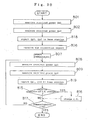
- step 601 upon receipt of the request for the allocation of the carrier frequency from mobile station 21 shown in step 703 or step 704 of the flow chart in Fig. 6 , base station 11 determines whether or not the request for the allocation of the carrier frequency is a request for an allocation of the non-adjacent carrier frequency or a request for an allocation of either the non-adjacent carrier frequency or the adjacent carrier frequency, in step 602. Then, in step 602, if the request for the allocation of the carrier frequency received from mobile station 21 is a request for the allocation of the non-adjacent carrier frequency, base station 11 decides the allocation of the non-adjacent carrier frequency in step 603.
- step 602 if the request for the allocation of the carrier frequency received from mobile station 21 is a request for the allocation of either the non-adjacent carrier frequency or the adjacent carrier frequency, base station 11 decides the allocation of any of the non-adjacent and adjacent carrier frequencies in step 604.
- step 605 base station 11 transmits the decided allocation of the carrier frequency to mobile station 21, which corresponds to step 705 in the flowchart of Fig. 6 .
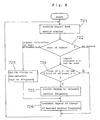
- base station 11 determines the sort of the notice in step 722.
- the notice from mobile station 21 involves request for allocation of the non-adjacent carrier frequency in step 710 of the flowchart of Fig. 6 and request for allocation of the adjacent carrier frequency in step 712. Further, nothing may be included in the notice.
- base station 11 decides the change of the carrier frequency to the non-carrier frequency in step 723.
- base station 11 compares the load of the carrier frequency now in use with the load of the adjacent carrier frequency in step 724.
- base station 11 decides the change of the carrier frequency to the adjacent carrier frequency in step 725. If the load of the carrier frequency now in use is equal or smaller than the load of the adjacent carrier frequency in step 724, base station 11 does not change the carrier frequency now in use.
- base station 11 does not receive a notice from mobile station 21 in step 722, base station 11 does not change the carrier frequency now in use.
- step 726 base station 11 transmits a notice of the change of the decided carrier frequency to mobile station 21, which corresponds to step 713 in the flowchart of Fig. 6 .
- mobile station 21 uses the non-adjacent carrier frequency for a signal of the uplink channel, mobile station 21 uses either carrier frequency Ga1 or carrier frequency Ga2 in which a signal of the uplink channel is also not adjacent to a signal of cellular system B.
- mobile station 21 uses the adjacent carrier frequency as a signal of the uplink channel, it selects and uses any signal of the downlink channel among carrier frequencies Ga1 to Ga3.
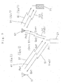
- Fig. 9 shows a case when in the cellular system shown Fig. 2 , base station 11 transmits a perch channel and communication channel of a downlink channel using carrier frequency Ga3, base station 61 a perch channel and a communication channel of the downlink channel using carrier frequency Gb1, base station 21 a communication channel of an uplink channel using carrier frequency Fa3, and base station 71 a communication channel of the uplink channel using carrier frequency Fb1.
- the communication channel of the uplink channel of base station 21 using carrier frequency Fa3 causes interference of adjacent frequencies to the communication channel of the uplink channel of mobile station 71.
- the transmission power of the perch channel of base station 61 is denoted by Pp2, and the received power Qp2 in its mobile station is denoted by Qp2. Furthermore, the transmission power of mobile station 21 is denoted by Pt1; the received power in base station 11 of the signal from mobile station 21, Qt1; and the adjacent frequency from mobile station 21 in base station 11, Qintf.
- L2 the propagation loss between base station 61 and mobile station 21
- Aadj the suppression amount of the leakage power to the adjacent frequency
- Qp2, Qt1, Qintf and L2 denote a short interval median excluding a variation in phasing, and it is assumed that the propagation loss of the uplink channel and the propagation loss in the are equal to each other.
- a relationship between propagation loss L2, transmission power Pp2 of the perch channel and received power Qp2 is expressed by the following equation:.
- L ⁇ 2 Pp ⁇ 2 - Qp ⁇ 2
- Qintfmax Qintf > Pt ⁇ 1 - Pp ⁇ 2 + Qp ⁇ 2 - Aadj
- threshold Qth1 is set also depending on suppression amount Aadj of the leakage power to the adjacent frequency.
- the adjacent carrier frequency when the interference of adjacent frequencies caused the base station of cellular system B, where is around the mobile station satisfies the equation (5), that is a condition for making it to be equal to or less than the permissible value, the adjacent carrier frequency is may be used. At this time, though the mobile station performs transmission with the maximum transmission power, the adjacent frequency interference signal power will be equal to or less than the allowable value.
- the transmitter of the base station in cellular system B which is around the mobile station, is such that it is capable of suppressing configured adjacent frequency interference similarly to mobile station 21. For this reason, when the adjacent carrier frequency is not used in the uplink channel, the interference of adjacent carrier frequencies to the mobile station from the base station in cellular system B can be prevented by constituting the mobile station such that it does ' not use the adjacent carrier frequency in the downlink channel, Therefore, adjacent interference can be prevented.
- a method of preventing interference of adjacent frequencies in a cellular system according to a second embodiment of the present invention is equivalent to the foregoing first embodiment except that a mobile station acquires information concerning a perch channel of another cellular system.
- base stations 11 to 13 do not inform base station 21 of information concerning the perch channel of cellular system B.
- mobile station 21 of cellular system A previously possesses information concerning the central frequency of carrier frequencies Fb 1 to Fb3 of the downlink channel which are set in cellular system B and information concerning plural codes which have a possibility to be used in the perch channels.
- mobile station 21 can immediately set the carrier frequency for receiving the perch channel. Furthermore, if mobile station 21 retrieves which code the base station is using among the plural codes, the mobile station 21 is able to receive the perch channel, so that a time necessary for receiving the perch channel can be shortened.
- a method of preventing interference of adjacent frequencies in a cellular system according to a third embodiment of the present invention is equivalent to the first embodiment except for setting threshold Qth1.
- threshold Qth1 instead of threshold Qth1 in the first embodiment, a value is used, which is obtained by adding threshold Qth2 that is a certain value to received power Qp1 of the perch channel of cellular system A measured by the mobile station.
- base stations 11 to 13 and base stations 61 to 63 notify the mobile station about information of the transmission power of the perch channel itself in the perch channel.
- the mobile station can acquire the information concerning the transmission power.
- Fig. 10 is a flowchart showing an operation when mobile station 21 sets a signal of the uplink channel and performs communication.
- mobile station 21 When a request for a communication with base station 11 occurs, mobile station 21 measures received power Qp1 of the perch channel of base station 11 in cellular system A in step 801. Further, in step 802, mobile station 21 measures received power Qp2 of the perch channel of base station 61 in cellular system B in step 802. In step 803, mobile station 21 decides whether or not received power Qp2 is larger than the sum of received power Qp1 and threshold Qth2. In step 803, when received power Qp2 is larger than the sum of received power Qp1 and threshold Qth2, mobile station 21 requests from base station 11 the non-adjacent carrier frequency which is not adjacent to carrier frequencies Fb1 to Fb3 of cellular system B in step 804. At this time, base station 11 determines the allocation of either carrier frequency Fa1 or carrier frequency Fa2 which is not adjacent to carrier frequency Fb3 as a signal of the uplink channel, and reports information concerning the allocation to mobile station 21.
- step 803 when received power Qp2 is equal to or less than the sum of received power Qp1 and threshold Qth2, mobile station 21 requests either the non-adjacent carrier frequency or the adjacent carrier frequency from base station 11 in step 805.
- base station 11 determines the allocation of a signal of the uplink channel among carrier frequencies Fa1 to Fa3, and reports information concerning the allocation to mobile station 21.
- step 806 base station 11 determines the carrier frequency allocated according to the request from mobile station 21 and reports to mobile station 21 this determination, and then mobile station 21 receives the allocation report.
- step 807 mobile station 21 starts the communication using the carrier frequency reported from base station 11.
- step 808 even during the communication with base station 11, mobile station 21 measures received power Qp1 of the perch channel of base station 11 with which a channel is established.
- step 809 mobile station 21 measures also the received powers of the perch channels of base stations 61 to 63 in cellular system B, and the received power of the perch channel of the base station closest to mobile station 21 is assumed to be received power Qp2, which exhibits the maximum received power among them.
- step 810 mobile station 21 decides whether or not received power Qp2 is larger than the sum of received power Qp1 and threshold Qth2.
- step 810 when received power Qp2 is larger than the sum of received power Qp1 and threshold Qth2, mobile station 21 decides whether or not the adjacent carrier frequency is being used in step 811.
- step 811 when the adjacent carrier frequency is being used in step 811, mobile station 21 requests the allocation of the non-adjacent carrier frequency from base station 11 in step 812. Upon receipt of this request, base station 11 determines the allocation of a signal of the uplink channel from carrier frequencies Fa1 and Fa2, and reports information concerning the allocation to mobile station 21.
- step 810 when received power Qp2 is equal to or less than the sum of received power Qp1 and threshold Qth2, in step 813 mobile station 21 decides whether or not the non-adjacent carrier frequency is being used.
- step 813 when the non-adjacent carrier frequency is being used, mobile station 21 reports that it is possible to use the adjacent carrier frequency to base station 11, in step 814. Base station 11 receives this report.
- base station 11 performs the change of the carrier frequency to carrier frequency Fa3.
- base station 11 reports to mobile station 21 the determination of the carrier frequency change.
- step 815 mobile station 21 decides whether or not mobile station 21 has received the report of the carrier frequency change.
- step 815 when mobile station 21 has received the report, mobile station 21 changes the carrier frequency according to the report in step 816.
- step 817 mobile station 21 decides whether or not the communication has been terminated, if the communication has not been terminated, mobile station 21 continues the communication, and iterates the procedures from step 808.
- carrier frequency Ga1 or Ga2 which is not adjacent to the carrier frequency of cellular system B is used also as a signal of the downlink channel.
- a signal of the downlink channel is selected among carrier frequencies Ga1 to Ga3, and used.
- the transmission power of the perch channel of base station 11 is denoted as Pp1
- the transmission power in its mobile station 21 is denoted as Qp1
- the propagation loss between base station 11 and mobile station 21 is denoted as L1.
- Pp1, Qp1 and L1 denote a short interval median.
- L ⁇ 1 Pp ⁇ 1 - Qp ⁇ 1
- received power Qt1 of a signal from mobile station 21 in base station 11 is given by the following equation (8).
- Qt ⁇ 1 Pt ⁇ 1 - L ⁇ 1
- Received power Qt1 controls transmission power Pt1 of the mobile station so that SIR is close to the target value. Assuming that the received power is Qtgt at the time when SIR comes to be equal to the target value, when transmission power Pt1 is controlled, received power Qtgt is expressed by the following equation (9).
- threshold Qth2 is set to the value shown in the following equation (12) from the equation (11).
- Qth ⁇ 2 Qintfmax - Qtgt + Aadj + Pp ⁇ 2 - Pp ⁇ 1
- threshold Qth2 will be set in association with a difference between transmission powers Pp1 and Pp2 of perch channels 31 and 81 that are being transmitted from base stations 11 and 71, respectively.
- the adjacent carrier frequency when the interference of adjacent frequencies satisfies the equation (11) that is a condition for allowing it to be equal to or less than the allowable value, the adjacent carrier frequency is sometimes used. At this time, the mobile station controls the transmission power, so that the interference of adjacent frequencies signal power will be equal to or less than the allowable value.
- the non-adjacent carrier frequency is used, so that no interference of adjacent frequencies occurs. Therefore, it is possible to prevent the interference of adjacent frequencies.
- the mobile station can prevent the interference of adjacent frequencies similarly to the first embodiment, and the range where the adjacent carrier frequency can not be used is narrowed, so that the range where the adjacent carrier frequency can be used is widened, resulting in an increase in a frequency efficiency.
- This embodiment is applied to the cellular system shown in Fig. 2 similarly to the first embodiment.
- Mobile station 21 measures the received powers of the perch channels of base stations 61 to 63 in cellular system B by utilizing an idle-time of downlink channel 41. However, where no idle-time is available, it is impossible to measure the received powers of the perch channels of base stations 61 to 63 in cellular system B.
- base station 11 selects and allocates Fa3 that is the carrier frequency which is adjacent to carrier frequencies Fb1 to Fb3 of the uplink channel in cellular system B.
- base station 11 selects and allocates either Fa1 or Fa2 that is carrier frequency which is not adjacent to carrier frequencies Fb1 to Fb3 of the uplink channel in cellular system B.
- the base station preferentially allocates the adjacent carrier frequencies to the mobile station which is capable of measuring the received power of the perch channel of the signal in cellular system B, and allocates the non-adjacent carrier frequency to the mobile station which is incapable of measuring the received power of the perch channel of the signal in cellular system B.
- the mobile station can prevent the interference of adjacent frequencies similarly to the first embodiment, and the base station never allocates the adjacent carrier frequency to the mobile station which has no so-called idle downlink channel because of continuous receipt of the communication channel of the downlink channel.
- This embodiment is applied to the cellular system shown in Fig. 2 similarly to the first embodiment.
- Base stations 11 to 13 and base stations 61 to 63 notify information concerning the transmission power of the perch channel itself in the perch channel, and the mobile station receives the information concerning the transmission power when the mobile station measures the received power of the perch channel.
- the mobile station in this embodiment computes the upper limit Pmaxtmp of the transmission power which allows the interference of adjacent frequencies to be equal to or less than the allowable value, when the adjacent carrier frequency is used. Moreover, the mobile station obtains received power Qmax of the base station at that time from upper limit Pmaxtmp. When upper limit Pmaxtmp is smaller than received power Qtgt, the mobile station request the allocation of the adjacent carrier frequency from the base station.
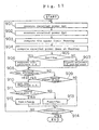
- Fig. 11 is a flowchart showing an operation when mobile station 21 sets a signal of the channel to perform the communication.
- base station 11 in this embodiment is the same as that of base station 11 in the first embodiment described by the flowchart of Figs. 7 and 8 , and descriptions for it are omitted.
- mobile station 21 measures received power Qp1 of the perch channel of base station 11 in cellular system A in step 901. Furthermore, mobile station 21 measures received power Qp2 of the perch channel of base station 61 in cellular system B in step 902. Then, in step 903, when the adjacent carrier frequency is used, mobile station 21 computes the upper limit Pmaxtmp of the transmission power which allows the interference of adjacent frequencies to be equal to or less than the allowable value, and computes received power Qmax in base station 11 at the time of that transmission power in step 904.
- step 905 mobile station 21 decides whether or not received power Qtgt at the time when SIR of the signal of the uplink channel in the base station comes to be the target value is larger than received power Qmax.
- step 905 if received power Qtgt is larger than received power Qmax, since with the usage of the adjacent carrier frequency it is impossible to make SIR larger than the target value in spite of the fact that the transmission power is made to be larger than upper limit Pmaxtmp, mobile station 21 requests from base station 11 the adjacent carrier frequency which is not adjacent to carrier frequencies Fb1 to Fb3 of cellular system B.
- base station 11 determines the allocation of either carrier frequency Fa1 or Fa2 which is not adjacent to carrier frequency Fb3, as a signal of the uplink channel, and reports information concerning the allocation to mobile station 21.
- step 905 when received power Qmax is equal to or less than received power Qtgt, since in spite of the use of the adjacent carrier frequency, SIR of the signal of the uplink channel can be made to be more than the target value while keeping the transmission power equal to or less than the upper limit Pmaxtmp, mobile station 21 reports that the it is possible to use adjacent carrier frequency to base station 11 in step 907.
- base station 11 determines the signal of the uplink channel to be allocated among carrier frequencies Fa1 to Fa3, and reports information of the allocation to mobile station 21.
- base station 11 determines the carrier frequency to be allocated in response to the request from mobile station 21, and reports it to mobile station 21.
- mobile station 21 Upon receipt of the new allocation report of the carrier frequency, mobile station 21 set the reported carrier frequency in step.
- upper limit Ptmax of the transmission power is made to be equal to upper limit Pmaxtmp in step 912.
- maximum transmission power Pmax of the transmitter of mobile station 21 is made to be equal to upper limit Ptmax of the transmission power.
- mobile station 21 set the upper limit of the transmission power to Ptmax and starts the communication. During the communication, mobile station 21 repeats the procedure from step 901, and when mobile station 21 receives the report of the frequency change in step 909, mobile station 21 sets the carrier frequency, and updates also upper limit Ptmax of the transmission power.
- Ga1 or Ga2 that is the carrier frequency which is not adjacent to the carrier frequency of cellular system B, is used also as the signal of the downlink channel.
- the signal of the downlink channel is selected from among Ga1 to Ga3 and used.
- Pmaxtmp Qintfmax + Pp ⁇ 2 + Aadj - Qp ⁇ 2
- the mobile station receives a value of the transmission power of perch channel 81 which is reported from base station 61 and uses it as Pp2.
- the received power in the base station at the time when the transmission power is equal to Pmaxtmp must be equal to or more than target value Qtgt.
- Transmission power Qmax in base station 11 at the time when the transmission power of base station 21 is equal to Pmaxtmp is given by the following equation (15).
- the mobile station receives a value of the transmission power of perch channel 31 which is reported from base station and uses it as Pp1.
- the equation (13) is satisfied without making the transmission power larger than Pmaxtmp, so that the interference of adjacent frequencies will be equal to or less than the allowable value.
- the transmission power in which a received quality is a target is larger than Pmaxtmp in the base station, the non-adjacent carrier frequency is used. Accordingly, the interference of adjacent frequencies can be prevented.
- the adjacent carrier frequency is used only when no interference of adjacent frequencies occurs in spite of the transmission with Pmax.
- a range where the adjacent carrier frequency can not be used is narrowed by using Pmaxtmp smaller than Pmax.
- the mobile station can prevent the interference of adjacent frequencies similarly to the first embodiment, and the range where the adjacent carrier frequency can not be used is narrowed, so that the range where the adjacent carrier frequency can be used is widened, resulting in an increase in a frequency efficiency.
- the sixth embodiment is applied to the cellular system shown in Fig. 2 , and the sixth embodiment differs from the first embodiment in the following points.
- the carrier frequency requested is selected using threshold Qth3 smaller than threshold Qth1 in addition to threshold Qth1 in the first embodiment.
- the mobile station in this embodiment uses the non-adjacent carrier frequency.
- the mobile station preferentially uses the adjacent carrier frequency.
- the mobile station uses any carrier frequency selected from all carrier frequencies.
- the mobile station in this embodiment decides that a possibility that received power Qp2 will exceed threshold Qth1 from a movement by the mobile station is low, and preferentially uses the adjacent carrier frequency.
- the mobile station does not use the adjacent carrier frequency as possible.
- Fig. 12 is a flowchart in which mobile station 21 sets a signal of the uplink channel and performs communication.
- mobile station 21 measures received power Qp2 of a perch channel of base station 61 in cellular system B in step 1001. In step 1002, it is decided whether or not received power Qp2 is larger than threshold Qth1. When Qp2 is larger than threshold Qth1 in step 1002, mobile station 21 requests a non-adjacent carrier frequency which is not adjacent to carrier frequencies Fb1 to Fb3 of cellular system B in step 1003. In step 1002, when Qp2 is equal to or less than threshold Qth1, mobile station 21 decides whether or not third threshold Qth3 is larger than Qp2 in step 1004.
- step 1004 when Qp2 is equal to or less than third threshold Qth3, mobile station 21 requests either a non-adjust carrier frequency or an adjacent carrier frequency from base station 11 in step 1005.
- step 1004 when threshold Qth3 is larger than Qp2, mobile station 21 requests the adjacent frequency in step 1006.
- Base station 11 determines the carrier frequency to be allocated in response to the request from mobile station 21, and reports the carrier frequency to be allocated to mobile station 21.
- Mobile station 21 receives the allocation report in step 1007.
- mobile station 21 starts communication using the carrier frequency reported from base station 11 in step 1008.
- mobile station 21 measures the received power of the perch channel of each base stations 61 to 63 of cellular system B in step 1009, and adopts the received power of the perch channel of the base station closest to mobile station 21 as Qp2.
- the base station closest to mobile station 21 exhibits the largest received power.
- mobile station 21 in step 1010 decides whether or not received power Qp2 is larger than threshold Qth1.
- mobile station 21 in step 1011 decides whether or not the adjacent carrier frequency is being used.
- mobile station 21 requests the allocation of the non-adjacent carrier frequency from base station 11 in step 1012.
- step 1010 when received power Qp2 is equal to or less than threshold Qth1, mobile station 21 in step 1013 decides whether or not threshold Qth3 is larger than received power Qp2. In step 1013, when threshold Qth3 is larger than received power Qp2, mobile station 21 decides in step 1014 whether or not the non-adjacent carrier frequency is being used.
- step 1014 when the non-adjacent carrier frequency is being used, mobile station 21 reports to base station 11 in step 1015 that the adjacent carrier frequency can be used. In the case where the carrier frequency is changed, base station 11 reports to mobile station 21 the determination of the change.
- step 1016 mobile station 21 decides whether or not the report for changing the carrier frequency is received.
- step 1016 when the report for changing the carrier frequency is received, mobile station 21 changes the carrier frequency now in use to the carrier frequency reported, in step 1017.
- step 1018 mobile station 21 decides whether or not the communication has been terminated, and if the communication has not been terminated, mobile station 21 continues the communication and iterates the procedure from step 1009.
- base station 11 Upon receipt of the request for the carrier frequency allocation from mobile station 21 in step 601, base station 11 decides in step 602 whether the request for the carrier frequency allocation is for the non-adjacent carrier frequency and the adjacent carrier frequency, or for either the non-adjacent carrier frequency or the adjacent carrier frequency.
- base station 11 determines the allocation of the adjacent carrier frequency in step 606, and transmits the report of the carrier frequency allocation to mobile station 21 in step 602.
- a method for setting threshold Qth1 is the same as that of the first embodiment. Furthermore, third threshold Qth3 is set to be a smaller value than that of Qth1.
- the adjacent carrier frequency is allocated to a mobile station where Qp2 is fairly smaller than the first threshold and the non-adjacent carrier frequency is allocated to a mobile station where Qp2 is close to the first threshold, a frequency of the carrier frequency change can be reduced while preventing the interference of adjacent frequencies similarly to the first embodiment.
- This embodiment is applied to the cellular system shown in Fig. 2 similarly to the third embodiment and is different from the third embodiment only in the following points.
- a carrier frequency requested is selected using threshold Qth4 smaller than threshold Qth2 in addition to threshold in the
- the mobile station in this embodiment uses the non-adjacent carrier frequency, and when received power Qp2 is smaller than the sum of threshold Qth4 and threshold Qp1, mobile station preferentially uses the adjacent carrier frequency.
- received power Qp2 is between the sum of thresholds Qth4 and received power Qp1 and the sum of thresholds Qth2 and received power Qp1, mobile station uses any of all of the carrier frequencies.
- the mobile station in this embodiment uses the adjacent carrier frequency as possible and reduces a frequency of the carrier frequency change.
- Fig. 14 is a flow chart showing an operation at the time when mobile station 21 set a signal of the uplink channel and performs communication.
- base station 11 in this embodiment is the same as that of that of base station 11 in the sixth embodiment described by the flow chart of Figs. 8 and 13 , and descriptions for it are omitted.
- mobile station 21 measures received power Qp1 of a perch channel of base station 11 in cellular system A in step 1101, and, in step 1102, further measures received Qp2 of a perch channel of base station 61 in cellular system B.
- mobile station 21 decides whether or not received power Qp2 is larger than a sum of received power Qp1 and threshold Qth2.
- mobile station 21 requests a non-adjacent carrier frequency which is not adjacent to carrier frequencies Fb1 to Fb3 of cellular system B from base station 11 in step 1104.
- base station 11 determines the allocation of Fa1 or Fa2 which is not adjacent to carrier frequency Fb3 as a signal of the uplink channel, and reports information concerning the allocation to mobile station 21.
- mobile station 21 in step 1105 decides whether or not fourth threshold Qth4 is larger than a difference between received powers Qp2 and Qp1.
- mobile station 21 requests a non- adjacent frequency or an adjacent frequency from base station 11 in step 1106.
- mobile station 21 requests the adjacent carrier frequency from base station 11 in step 1107.
- Base station 11 determines a carrier frequency to be allocated in response to the request from mobile station 21, and mobile station 21 receives the allocation report in step 1108.
- mobile station 21 starts communication using the carrier frequency reported from base station 11 in step 1109. Even during the communication with base station 11, mobile station 21 measures received power Qp1 of the perch channel of base station 11 from which a channel is established thereto in step 1110. Then, mobile station 21 measures also the received power of the perch channel of each base stations 61 to 63 in cellular system B in step 1111, and adopts as Qp2 the received power of the perch channel of the base station closest to mobile station. This base station closest to the mobile station exhibits the largest received power.
- step 1112 mobile station 21 decides whether or not received power Qp2 is larger than the sum of received power Qp1 and threshold Qth2.
- step 1112 when received power Qp2 is larger than the sum of the received power Qp1 and threshold Qth2, mobile station 21 in step 1113 decides whether or not the adjacent carrier frequency is being used.
- step 1113 when the adjacent carrier frequency is being used, mobile station 21 requests an allocation of a non-adjacent carrier frequency from base station 11 in step 1114.
- base station 11 determines the allocation of the carrier frequency to a signal of the uplink channel from carrier frequencies Fa1 and Fa2, and reports information about the allocation to mobile station 21.
- step 1112 when received power Qp2 is equal to or less than the sum of received power Qp1 and threshold Qth2, mobile station 21 in step 1115 decides whether or not fourth threshold Qth4 is larger than the difference between received powers Qp2 and Qp1.
- step 1115 when threshold Qth4 is larger than the difference between received powers Qp2 and Qp1, mobile station 21 decides in step 1116 whether or not the non-adjacent carrier frequency is being used.
- step 1116 when the non-adjacent carrier frequency is being used, mobile station 21 reports to base station 11 that the adjacent carrier frequency can be used, in step 1117.
- step 1118 mobile station 21 decides whether or not the report of the carrier frequency change is received.
- step 1118 when the report of the carrier frequency change is received, mobile station 21 changes the carrier frequency now in use to the carrier frequency reported in step 1119.
- step 1120 mobile station 21 decides whether or not the communication has been terminated, and if the communication has not been terminated, mobile station 21 continues the communication and repeats the operation from step 1110.
- the non-adjacent carrier frequency is used for a signal of the uplink channel, also as a signal of the downlink channel, used is Ga1 or Ga2 that is a carrier frequency which is not adjacent to the carrier frequency of cellular system B. Furthermore, when the adjacent carrier frequency is used for a signal of the uplink channel, a signal of the downlink channel is selected among received powers Ga1 to Ga3, and used.
- threshold Qth2 is set to be smaller than threshold Qth2.
- the interference of adjacent frequencies can be prevented similarly to the third embodiment.
- received power Qp2 is fairly smaller than the sum of the received power Qp1 and second threshold Qth2 during the use of the adjacent carrier frequency, mobile station moves during communication, whereby received power Qp2 comes to be larger than the sum of received power Qp1 and second threshold Qth2.
- a necessity to change the carrier frequency would be less, compared to the case where received power Qp2 is close to the sum of the received power Qp2 and second threshold Qth2.
- the adjacent carrier frequency is allocated to a mobile station in which received power Qp2 is fairly small compared to the sum of the received power Qp1 and second threshold Qth2, and the non-adjacent carrier frequency is allocated to a mobile station in which received power Qp2 is close to the sum of received power Qp1 and second threshold Qth2. Therefore, a frequency of the carrier frequency change can be reduced while preventing the interference of adjacent frequencies similarly to the third embodiment.
- the mobile station comprises a movement speed estimator (not shown), and this embodiment is the same as the first to seventh embodiments except that when a movement speed of the mobile station is larger than a certain threshold speed, the non-adjacent carrier frequency is allocated in spite of the fact that the adjacent carrier frequency is used.
- the received power of the perch channel varies in a short cycle by phasing.
- the movement speed estimator obtains the median of the received power, while receiving the received power of the perch channel of base station 11 with which a channel to be established. Then, the movement speed estimator counts the number of times of crossing of the received power value over its median, whereby the movement speed of the mobile station is estimated.
- base station 11 In the beginning of communication between base station 11 and mobile station 21, when the estimated movement speed is larger than the threshold speed, mobile station 21 requests an allocation of a non-adjacent carrier frequency, and base station 11 allocates carrier frequency Fa1 or Fa2 to an uplink channel, which is the non-adjacent carrier frequency. On the other hand, when the estimated movement speed is equal to or less than the threshold speed, base station 11 sets the carrier frequency and performs the communication by the method of the seventh embodiment, as described with reference to Fig. 14 .
- a frequency of the carrier frequency can be reduced, while preventing the interference of adjacent frequencies similarly to the seventh embodiment.
- the movement speed of the mobile station is high during the usage of the adjacent carrier frequency, the amount of the variation of received powers Qp1 and Qp2 during the communication is large. Therefore, received power Qp2 will be larger than the sum of received power Qp1 and second threshold Qth2 due to the movement of the mobile station during the communication, so that a possibility that the carrier frequency change is required is comparatively large.
- the frequency of the carrier frequency change can be more reduced.
- the method of preventing interference of adjacent frequencies in a cellular system according to the ninth embodiment is applied to the cellular system shown in Fig. 15 .
- the same reference numerals as those in Fig. 2 show the identical components.
- a cellular system C composed of base stations 161 to 169 and mobile station 171 is provided, instead of the cellular system C composed of base stations 61 to 63 and mobile station 171.
- the cellular system C is a micro cellular system, and transmission outputs of base stations 161 to 169 are greatly decreased, compared to base stations 11 to 13 constituting the macro cellular system.
- This embodiment is the same as the first to eighth embodiments except for the above-described portions.
- the two cellular systems including the macro cellular system and the micro cellular system exist in the same service area, and even when the sizes of them are different, the interference of adjacent frequencies can be prevented.
- the method according to this embodiment is applied to the cellular system assuming the structure shown in Fig. 16 .
- the same reference numerals as those in Fig. 2 show the same components.
- a cellular system D composed of base stations 111 to 119 and mobile station 121 is provided, instead of the cellular system A composed of base stations 111 to 113 and mobile station 121.
- the cellular system D is a micro cellular system, and transmission outputs of base stations 111 to 119 are greatly decreased, compared to base stations 61 to 63 constituting the macro cellular system.
- This embodiment is the same as the first to eighth embodiments except for the above-described portions.
- the two cellular systems including the macro cellular system and the micro cellular system exist in the same service area, and even when the sizes of them are different, the interference of adjacent frequencies can be prevented.
- carrier frequencies Fa1 to Fa3 are allocated to signals of the uplink channel of cellular system A; carrier frequencies Ga1 to Ga3, signals of the downlink channel thereof; carrier frequencies Fb1 to Fb3, signal of the uplink channel of cellular system B; and carrier frequencies Gb 1 to Gb3, signals of the downlink channel thereof.
- carrier frequencies Fa1 to Fa3 are set in base stations 11 and 13, only carrier frequencies Fa1 and Fa2 are set in base station 12.
- carrier frequencies Ga1 to Ga3 are set in base stations 11 and 13, only carrier frequencies Ga1 and Ga3 are set in base station 12.
- the mobile station of cellular system A when the mobile station of cellular system A selects the signal of the uplink channel, the mobile station measures the received power of the perch channel transmitted from a base station of cellular system B, and a base station in which carrier frequency Fb1 adjacent to a signal of the uplink channel of cellular system A is not set is excluded as an object to be measured.
- mobile station 21 Since in base station 61, carrier frequency Fb1 is not set, mobile station 21 excludes the received power of the perch channel of base station 61 as objects to be measured, and since base stations 62 and 63 use carrier frequency Fb1, mobile station 21 measures the received power of the perch channel of each of these base stations, and selects and uses a signal of the uplink channel similarly to the first embodiment.
- This embodiment is the same as the first embodiment except for the above-described portions.
- a carrier frequency is selected without measuring a received power of its perch channel.
- the mobile station gives the interference of adjacent frequencies to such base station.
- the application of the interference of adjacent frequencies can be prevented similarly to the first embodiment.
- base stations 12 and 61 are supposed as base stations provided in the suburbs where the volume of traffic is small. In areas where the volume of traffic is small, a problem that all channels come to be busy hardly occurs in spite of decreasing the number of carrier frequencies used. For this reason, the measurement of the received power of the perch channel can be omitted by a limitation of the carrier frequencies which are set only to specified base stations like this embodiment.
- This embodiment is equivalent to the first embodiment except that setting of the carrier frequency is different from that of the first embodiment.
- the carrier frequencies shown in Fig. 17 are set in cellular systems A and B.
- carrier frequencies Fa1 to Ga3 are allocated for signals of the uplink channel, and the carrier frequencies Ga1 and Ga3 are allocated for signals of the downlink channel.
- carrier frequencies Fb1 to Fb3 are allocated for signals of the uplink channel, and carrier frequencies Gb1 and Gb3 are allocated for signals of the downlink channel.
- the frequency bands belonging to the different cellular systems are not adjacent to each other of the downlink channel, the frequency bands belonging to the different cellular systems are adjacent to each other of the uplink channel, the interference of adjacent frequencies can be prevented perfectly similar to the first embodiment.
- the interference of adjacent frequencies applied to the base station by the mobile station is prevented by selectively using the carrier frequencies of the uplink channel.
- the interference of adjacent frequencies applied to the mobile station by the base station is prevented.
- the interference of adjacent frequencies by the downlink channel is not a severe problem as long as the interference of adjacent frequencies by the uplink channel is prevented by monitoring.
- the suppression degree for the leakage power of the transmitter of the base station is low, a possibility that the interference of adjacent frequencies by the downlink channel will be a problem is expected.
- mobile station 21 uses threshold Qmth1 instead of threshold Qth1, and when received power Qp2 exceeds threshold Qmth1, mobile station 21 changes the carrier frequency of communication channel 41 of the downlink channel, and the interference of adjacent frequencies from base station 61 is prevented.
- an interference of adjacent frequencies signal power from base station 61 in mobile station 21 is denoted as Qmintf, and a suppression amount for a leakage power to an adjacent frequency is denoted as Absadj.
- Pbs2 denotes a transmission power of base station 61. Values other than these are the same as those of the first embodiment.
- the carrier frequency of the uplink channel is selectively used in order to prevent the interference of adjacent frequencies in the second to twelfth embodiment.
- the carrier frequency of the downlink channel is selectively used similarly to the thirteenth embodiment, the interference of adjacent frequencies applied to the mobile station from the base station can be prevented.
- thresholds Qth3 and Qth4, and threshold speed are a fixed value previously determined, the present invention is not limited to this, these values are flexibly may be changed according to the number of mobile stations in a signal of each carrier frequency, a channel quality, an interference signal power and the like.
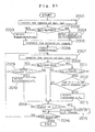
- mobile station 21 decides whether or not received power Qp2 of the perch channel of base station 61 is larger than threshold Qth1, and makes a report to change an adjacent or non-adjacent carrier frequency based on a measurement result.
- a comparison of the received power Qp2 of the perch channel of base station 61 with threshold Qth1 is not made in mobile station 21, but the comparison is made in base station 11.
- mobile station 21 measures received power Qp2, and reports the measurement value to base station 11. In base station 11, the comparison of the measurement value of received power Qp2 with threshold Qth1 is made.
- FIG. 18 An operation of mobile station 21 in this embodiment is shown in the flowchart of Fig. 18 , and an operation of base station 11 is shown in the flowchart of Fig. 19 .
- the flowchart of Fig. 18 comprises step 716 instead of steps 702 to 704 of Fig. 6 , and comprises step 717 instead of steps 708 to 712 of Fig. 6 .
- Other steps of Fig. 18 are the same procedures as those of Fig. 6 .
- base station 21 in this embodiment will be described with reference to Fig. 18 .
- mobile station 21 When a request for communication with base station 11 occurs, mobile station 21 measures received power Qp2 of a perch channel of base station 61 in cellular system B in step 701. Subsequently, mobile station 21 reports received power Qp2 measured to base station 11 in step 716. Base station 11 determines the carrier frequency to be allocated based on received power Qp2 reported from mobile station 21, and reports it to mobile station 21. Mobile station 21 receives the allocation report in step 705.
- mobile station 21 starts the communication using the carrier frequency reported from base station 11 in step 706.
- mobile station 21 measures received power Qp2 of a perch channel of each of base stations 61 to 63 even during the communication, in step 707.
- mobile station 21 reports to base station 11 the received power Qp2 of the perch channel of the base station closest to mobile station 21. In this base station, the received power is maximum.
- base station 11 Based on received power Qp2 reported from mobile station 21, base station 11 decides whether or not the carrier frequency now in use is to be changed, and when it is to be changed, base station 11 sends a carrier frequency change report to mobile station 21.
- step 713 when mobile station 21 receives the carrier frequency change report from base station 11, mobile station 21 change the carrier frequency now in use to the reported carrier frequency. Then, in step 715, mobile station 21 decides whether or not the communication is terminated, if the communication has been terminated, mobile station 21 finishes the procedure. If the communication has not been terminated, mobile station 21 iterates the foregoing procedure from step 70 7.
- step 1801 base station 11 receives the report concerning received power Qp2 sent from mobile station 21.
- step 1801 corresponds to step 716 in Fig. 18 .
- step 1802 base station 11 decides whether or not received power Qp2 is larger than threshold Qth1.
- base station 11 selects a non-adjacent carrier frequency in step 1803.
- step 1802 when received power Qp2 is equal to or less than threshold Qth1, base station 11 selects either a non-adjacent carrier frequency or an adjacent carrier frequency in step 1804.
- base station 11 sends an allocation report for the selected carrier frequency to mobile station 21 in step 1805.
- This step 1805 corresponds to step 705 in Fig. 18 .
- step 1806 base station 11 starts communication with mobile station 21 using the carrier frequency selected in base station 11.
- mobile station 21 measures received power Qp2 of the perch channel of each of base station 61 to 63 in cellular system B even during the communication, and sends a measurement result of received power Qp2.
- Base station 11 receives the report concerning received power Qp2 in step 1807.
- step 1808 base station 11 decides whether or not received power Qp2 received from mobile station 21 is larger than threshold Qth1.
- base station 11 decides whether or not the adjacent carrier frequency is being used, in step 1809.
- base station 11 selects the non-adjacent carrier frequency in step 1810.
- step 1808 when received power Qp2 is equal to or less than threshold Qth1, base station 11 decides whether or not the non-adjacent carrier frequency is being used, in step 1811.
- step 1811 when the non-adjacent carrier frequency is being used, the base station 11 decides whether or not a load of the carrier frequency now in use is larger than a load of the adjacent carrier frequency, in step 1812.
- step 1812 when the load of the carrier frequency now in use is larger than the load of the adjacent carrier frequency, base station 11 selects the adjacent carrier frequency in step 1813.
- base station 11 does not perform the change of the carrier frequency.
- base station 11 decides whether or not there is the change of the carrier frequency, and when there is the change of the carrier frequency, base station 11 sends a carrier frequency change report to mobile station 21.
- This step 1815 corresponds to step 713 in Fig. 18 .
- step 1816 base station 11 decides whether the communication has been terminated , and if the communication has been terminated, base station 11 finishes the procedure. If the communication has not been terminated, base station 11 continues the communication, and iterates the foregoing procedure from step 1807.
- the base station sends carrier selection rule information (i.e., information concerning a carrier frequency which the mobile station has an obligation to measure) by a BCCH (Broad Cast Channel; report channel), and the mobile station receives the carrier selection rule information from the base station.
- carrier selection rule information i.e., information concerning a carrier frequency which the mobile station has an obligation to measure
- BCCH Broad Cast Channel; report channel
- the call-setup direction is a direction for setting a channel
- the inter-frequency handover is an operation to change a carrier frequency now in use to a different carrier frequency
- mobile station 21 decides whether or not received power Qp2 of the perch channel of base station 61 is larger than the sum of threshold Qth2 and received power Qp1 of the perch channel of base station 11, and mobile station 21 performs the report requesting either a non-frequency carrier frequency or. an adjacent carrier frequency based on the decision result.
- the comparison of received power Qp2 of the perch channel of base station 61 with the sum of threshold Qth2 and received power Qp1 is not made in mobile station 21, but in base station 11.
- mobile station 21 measures received power Qp2 and received power Qp1, and informs base station 11 of these values.
- the comparison of received power Qp2 with the sum of threshold Qth2 and received power Qp1 is made in base station 11.
- FIG. 20 An operation of mobile station 21 in this embodiment is shown in the flowchart of Fig. 20 , and an operation of base station 11 is shown in the flowchart of Fig. 21 .
- the flowchart of Fig. 20 comprises step 818 instead of steps 803 to 805 in the flowchart of Fig. 10 , and comprises step 819 instead of steps 810 to 814 in the flowchart of Fig. 10 .
- Other steps in the flowchart of Fig. 20 are the same procedures as those of Fig. 10 .
- mobile station 21 When a request for communication with base station 11 occurs, mobile station 21 measures received power Qp1 of a perch channel of base station 11 in cellular system A in step 801, and further measures received power Qp2 of a perch channel of base station 61 in cellular system B in step 802. Subsequently, mobile station 21 informs base station 11 of the measured powers Qp1 and Qp2 in step 818.
- Base station 11 determines a carrier frequency to be allocated based on received powers Qp1 and Qp2 informed from mobile station 21 and informs mobile station 21 of it. Mobile station 21 receives its allocation report in step 806.
- step 807 mobile station 21 starts communication using the carrier frequency informed from base station 11. Subsequently, in step 808, mobile station 21 measures received power Qp1 of a perch channel of base station 11 in cellular system A even during the communication, and mobile station 21 further measures received power Qp2 of a perch channel of each of base stations 61 to 63 in cellular system B in step 809. Then, in step 819, mobile station 21 informs base station 11 of the measured received powers Qp1 and Qp2.
- base station 11 determines whether or not the carrier frequency now in use is to be changed. If the carrier frequency is changed, base station 11 sends a carrier frequency change report to mobile station 21.
- step 815 mobile station 21 decides whether or not the carrier frequency change report from base station 11 has been received. If mobile station 21 has received the carrier frequency change report from base station 11 in step 815, mobile station 21 changes the carrier frequency now in use to the carrier frequency reported in step 816. Then, in step 817, mobile station 21 decides whether or not the communication has been terminated, if the communication has been terminated, the mobile station 21 finishes the procedure. If the communication has not been terminated, mobile station 21 repeats the foregoing procedures from step 808.
- step 2001 base station 11 receives the report concerning received powers Qp1 and Qp2 sent from mobile station 21.
- step 2001 corresponds to step 818 in Fig. 20 .
- step 2002 base station 11 decides whether or not received power Qp2 is larger than a sum of received power Qp1 and threshold Qth2.
- step 2002 if received power Qp2 is larger than the sum of received power Qp1 and threshold Qth2, base station 11 selects a non-carrier frequency in step 2003.
- step 2002 if received power Qp2 is equal to or less than the sum of received power Qp1 and threshold Qth2, base station 11 selects either an adjacent carrier frequency or an adjacent carrier frequency in step 2004.
- step 2005 base station 11 sends an allocation report concerning the selected carrier frequency to mobile station 21. This step 2005 corresponds to step 806 in Fig. 20 . Then, in step 2006, base station 11 starts communication with mobile station 21 using the carrier frequency selected in base station 11.
- mobile station 21 measures received power Qp1 of a perch channel of base station 11 in cellular system A even during the communication and sends it.
- mobile station 21 measures received power Qp2 of a perch channel of each of base stations 61 to 63 in cellular system B and sends them. For this reason, in step 2007, base station 11 receives the reports concerning received powers Qp1 and Qp2.
- step 2008 base station 11 decides whether or not received power Qp2 that has been received is larger than a sum of received power Qp1 and threshold Qth2. If received power Qp2 is a larger than the sum of received power Qp1 and threshold Qth2 in step 2008, in step 2009 base station 11 decides whether or not an adjacent carrier frequency is being used. If the adjacent carrier frequency is being used in step 2009, base station 11 selects a non-adjacent carrier frequency in step 2010.
- step 2011 base station 11 decides whether or not the non-adjacent carrier frequency is being used. If the non-adjacent carrier frequency is being used in step 2011, in step 2012 base station 11 decides whether or not a load of the carrier frequency now in use is larger than a load of the adjacent carrier frequency. If the load of the carrier frequency now in use is larger than the load of the adjacent carrier frequency in step 2012, base station 11 selects the adjacent carrier frequency in step 2013.
- base station 11 does not perform the change of the carrier frequency.
- base station 11 decides whether or not there is a change of the carrier frequency. If there is a change of the carrier frequency, base station 11 sends a carrier frequency change report to mobile station 21 in step 2015.
- the step 2015 corresponds to step 815 in Fig. 20 .
- step 2016, base station 11 decides whether or not the communication has been terminated. If the communication has been terminated, base station 11 finishes the procedure. If the communication has not been terminated, base station 11 continues the communication, and repeats the foregoing procedures from 2007.
- mobile station 21 reports a difference between received powers Qp1 and Qp2 to base station 11 instead of reporting received powers Qp1 and Qp2 to base station 11.
- steps 2002 and 2008 will be the procedures for comparing Qth2 with Qp2-Qp1.
- the decision procedure for the threshold and the received power which are measured in the mobile station in the first and third embodiments is performed in the base station.
- the mobile station may inform the base station of the measured received power or the movement speed, and the decision procedures between various kinds of thresholds and them may be performed in the base station.
- the mobile station in cellular A in the case where the mobile station in cellular A measures the received power of the perch channel in cellular system A during the communication, the mobile station in cellular A repeatedly measures the received power of the perch channel in cellular system B during the communication until the termination of the communication.
- the received power may be measured in a certain time interval which is previously determined or in a time interval every the report to the mobile station which is performed by the base station.
- the received power may be measured in a time interval which is determined according to a movement speed of the mobile station so that the received power is measured in a short time interval in proportion to the movement speed of the mobile station which is estimated by the mobile station or the base station.
- the received power may be measured when the mobile station measures the received pover of the perch channel of cellular system A and the received power changes in a predetermined rate.
- various ways are conceived. With any way, the present invention can be implemented without any trouble.
- one channel in a frequency band used in cellular system A is set as a carrier frequency adjacent to a frequency band of a down or uplink channel used in cellular system B.
- the present invention is not limited to this.
- the present invention can be applied to the case where a plurality of channels are set as an adjacent carrier frequency.
- the mobile station when a mobile station measures a received power of transmitting signals of a base station belonging to another cellular system, the mobile station measures the received of the perch channel.
- the present invention is not limited to this.
- the present invention is similarly applied to the case where a received power of a signal other than that signal in another cellular system is measured, as long as this signal is the one that is transmitted by the base station. It is satisfactory that the mobile station may measure all received powers in a frequency band of a carrier frequency which the base station belonging to another cellular system uses for transmitting.
- the mobile station may measure a received power of a control channel other than the perch channel.
Landscapes
- Engineering & Computer Science (AREA)
- Quality & Reliability (AREA)
- Computer Networks & Wireless Communication (AREA)
- Signal Processing (AREA)
- Mobile Radio Communication Systems (AREA)
Claims (49)
- Verfahren zum Verhindern einer Störung benachbarter Frequenzen, wobei in demselben Versorgungsbereich zwei Zellensysteme (A, B), die mehrere Basisstationen (11, 12, 13, 61, 62, 63) und wenigstens eine Mobilstation (21) umfassen, die für einen Aufwärtsstreckenkanal zueinander benachbarte Frequenzbänder (Fa1, Fa2, Fa3) nutzen, vorgesehen sind und wobei ein Signal für den von einer Mobilstation (21) eines Zellensystems (A) verwendeten Aufwärtsstreckenkanal für eine Basisstation (61, 62, 63) des anderen Zellensystems (B) eine Störung benachbarter Frequenzen (Fb1, Fb2, Fb3) verursachen kann, wobei das Verfahren die folgenden Schritte umfasst:bei der Mobilstation (21) des einen Zellensystems (A):Messen einer Empfangsleistung (Qp2) der von der Basisstation (61, 62, 63) des anderen Zellensystems (B) gesendeten Signale; undbei der Basisstation (11) und bei der Mobilstation des einen Zellensystems (A):Verwenden einer Trägerfrequenz (Fa1, Fa2), die zu der (Fb1, Fb2, Fb3) des anderen Zellensystems (B) nicht benachbart ist, als eine Trägerfrequenz eines Aufwärtsstreckenkanals, falls der Messwert (Qp2) größer als ein Schwellenwert (Qth1, Qp1+Qth2) ist,wobei die Messung an den Frequenzen (Gb1, Gb2, Gb3) von Signalen für den von einer Basisstation (61, 62, 63) des anderen Zellensystems (B) verwendeten Abwärtsstreckenkanal ausgeführt wird.
- Verfahren nach Anspruch 1, wobei der Schwellenwert (Qth1) in Abhängigkeit von dem Betrag (Aadj) der Unterdrückung der Leckleistung zu einer benachbarten Frequenz der Mobilstation (21) bestimmt wird.
- Verfahren nach Anspruch 1, wobei der Schwellenwert (Qp1 +Qth2) in Abhängigkeit von der Empfangsleistung (Qp1) der von der Basisstation (21) des einen Zellensystems (A) gesendeten Sendesignale bestimmt wird.
- Verfahren nach Anspruch 1, wobei der Schwellenwert (Qp1+Qth2) in Abhängigkeit von einer Differenz zwischen einer Sendeleistung (Pp1) der Sendesignale, die von einer Basisstation (11) gesendet werden, von der ein Kanal zu der Mobilstation (21) aufgebaut wird, und der Sendeleistung (Pp2) von Sendesignalen, die von einer Basisstation (61, 62, 63) des anderen Zellensystems (B) gesendet werden, bestimmt wird.
- Verfahren nach Anspruch 1, das ferner die folgenden Schritte umfasst:bei der Mobilstation (21) des einen Zellensystems (A):vorzugsweises Verwenden einer Trägerfrequenz (Fa1, Fa2), die zu einer Trägerfrequenz (Fb1, Fb2, Fb3) des von dem anderen Zellensystem (B) verwendeten Aufwärtsstreckenkanals nicht benachbart ist, wenn ein Signal für den Abwärtsstreckenkanal ununterbrochen empfangen wird; undMessen der Empfangsleistung (Qp2) von der Basisstation (61, 62, 63) des anderen Zellensystems (B) gesendeter Signale, wenn ein Signal des Abwärtsstreckenkanals intermittierend empfangen wird.
- Verfahren nach Anspruch 1, das ferner die folgenden Schritte umfasst:bei der Basisstation (11) und bei der Mobilstation (21) des einen Zellensystems (A):Verwenden einer Trägerfrequenz (Fa1, Fa2), die zu der (Fb1, Fb2, Fb3) des anderen Zellensystems (B) nicht benachbart ist, falls der Messwert (Qp2) größer als ein erster Schwellenwert (Qth1, Qp1 +Qth2) ist; undVerwenden einer Trägerfrequenz (Fa3), die zu der (Fb1, Fb2, Fb3) des anderen Zellensystems (B) benachbart ist, als eine Trägerfrequenz eines Aufwärtsstreckenkanals, falls der Messwert kleiner oder gleich einem zweiten Schwellenwert (Qth3, Qp1+Qth4) ist, der kleiner als der erste Schwellenwert (Qth1, Qp1+Qth2) ist.
- Verfahren nach Anspruch 6, wobei der erste Schwellenwert (Qp1+Qth2) auf der Grundlage einer Differenz zwischen einer Sendeleistung (Pp1) von Signalen, die von einer Basisstation (11) gesendet werden, von der ein Kanal zu der Mobilstation (21) aufgebaut wird, und einer Sendeleistung (Pp2) von Signalen, die von einer Basisstation (61, 62, 63) des anderen Zellensystems (B) gesendet werden, bestimmt wird.
- Verfahren nach Anspruch 6, wobei der erste Schwellenwert (Qp1+Qth2) auf der Grundlage einer Empfangsleistung (Qp1) von einer Basisstation (11) des einen Zellensystems (A) gesendeter Signale bestimmt wird.
- Verfahren nach Anspruch 1, wobei der Schritt des Messens einer Empfangsleistung den Schritt des Messens einer Empfangsleistung (Qp2) von der Basisstation (61, 62, 63) des anderen Zellensystems (B) gesendeter Signale unter Verwendung von Informationen, die von der Basisstation (11, 12, 13) desselben Zellensystems (A) gesendet werden, von Mittenfrequenzen (Gb1, Gb2, Gb3) von Signalen für den von einer Basisstation (61, 62, 63) des anderen Zellensystems (B) verwendeten Abwärtsstreckenkanal enthält.
- Verfahren nach Anspruch 1, wobei der Schritt des Messens einer Empfangsleistung den Schritt des Messens einer Empfangsleistung (Qp2) von der Basisstation (61, 62, 63) des anderen Zellensystems (B) gesendeter Signale unter Verwendung von Informationen, die Vorderhand von der Mobilstation (21) besessen werden, von Mittenfrequenzen (Gb1, Gb2, Gb3) von Signalen für den von einer Basisstation (61, 62, 63) des anderen Zellensystems (B) verwendeten Abwärtsstreckenkanal enthält.
- Verfahren nach Anspruch 1, wobei das eine Zellensystem (B) ein mikrostrukturiertes Zellensystem (C) ist, in dem die Sendeleistung jeder Basisstation (161, 162, 163) kleiner als ein vorgegebener Wert ist, und wobei das andere Zellensystem (A) ein makrostrukturiertes Zellensystem ist, in dem die Sendeleistung jeder Basisstation (11, 12, 13) größer als der vorgegebene Wert ist.
- Verfahren nach Anspruch 1, wobei das eine Zellensystem (B) ein makrostrukturiertes Zellensystem ist, in dem die Sendeleistung jeder Basisstation (61, 62, 63) größer als ein vorgegebener Wert ist, und das andere Zellensystem (A) ein mikrostrukturiertes Zellensystem (D) ist, in dem die Sendeleistung jeder Basisstation (111, 112, 113) kleiner als der vorgegebene Wert ist.
- Verfahren nach Anspruch 1,
wobei bei der Mobilstation (21) des einen Zellensystems (A) in dem Messschritt eine Trägerfrequenz (Fa3), die zu einer Trägerfrequenz (Fb1) des anderen Zellensystems (B) benachbart ist, als eine Trägerfrequenz eines Aufwärtsstreckenkanals zugeordnet wird. - Verfahren nach Anspruch 1, wobei die wenigstens eine Mobilstation (21) für einen Abwärtsstreckenkanal zueinander benachbarte Frequenzbänder (Ga1, Ga2, Ga3) nutzt und wobei ein Signal für den von einer Basisstation (61, 62, 63) des anderen Zellensystems (B) verwendeten Abwärtsstreckenkanal für eine Mobilstation (21) des einen Zellensystems (A) eine Störung benachbarter Frequenzen (Ga1, Ga2, Ga3) verursachen kann, wobei das Verfahren ferner die folgenden Schritte umfasst:bei der Basisstation (11) und bei der Mobilstation (21) des einen Zellensystems (A):Verwenden einer Trägerfrequenz (Ga1, Ga2), die zu der (Gb1, Gb2, Gb3) des anderen Zellensystems (B) nicht benachbart ist, als eine Trägerfrequenz eines Abwärtsstreckenkanals, falls der Messwert (Qp2) größer als ein Schwellenwert ist.
- Verfahren nach Anspruch 1, wobei der Schritt des Messens einer Empfangsleistung (Qp2) den Schritt des Messens eines Perch-Kanals (81) in den von der Basisstation (61, 62, 63) des anderen Zellensystems (B) gesendeten Signalen enthält.
- Verfahren nach Anspruch 1, wobei der Schritt des Verwendens einer Trägerfrequenz einen Schritt des Verwendens einer Trägerfrequenz (Ga1, Ga2), die zu einer Trägerfrequenz (Gb1, Gb2, Gb3) des Abwärtsstreckenkanals des anderen Zellensystems (B) nicht benachbart ist, als eine Trägerfrequenz eines Abwärtsstreckenkanals enthält, falls die Mobilstation (21) und die Basisstation eine Trägerfrequenz (Fa1, Fa2), die zu einer Trägerfrequenz (Fb1, Fb2, Fb3) des anderen Zellensystems (B) nicht benachbart ist, als eine Trägerfrequenz eines Aufwärtsstreckenkanals verwenden.
- Verfahren nach Anspruch 1, das ferner die folgenden Schritte umfasst:bei der Mobilstation (21):Messen der Empfangsleistung (Qp2) der in den Trägerauswahlregelinformationen angewiesenen Trägerfrequenzen (Fb1, Fb2, Fb3) zu der Zeit, zu der die Mobilstation eine Kommunikation mit der Basisstation (11) beginnt;Berichten des Messergebnisses (Qp2) an die Basisstation (11) unter Verwendung einer nicht benachbarten Trägerfrequenz (Fa1, Fa2), die zu der mit der gemessenen Trägerfrequenz gepaarten Trägerfrequenz (Fb1, Fb2, Fb3) nicht benachbart ist;bei der Basisstation (11):Empfangen des Messergebnisses von der Mobilstation;Auswählen einer nicht benachbarten Trägerfrequenz (Fa1, Fa2), falls die gemessene Empfangsleistung (Qp2) größer als ein Schwellenwert ist, und Auswählen einer verfügbaren Trägerfrequenz (Fa1, Fa2, Fa3), falls die gemessene Empfangsleistung kleiner oder gleich dem Schwellenwert ist;Senden einer Rufaufbauanweisung und Informieren der Mobilstation über die ausgewählte Trägerfrequenz;bei der Mobilstation (21):Beginnen der Kommunikation unter Verwendung der ausgewählten Trägerfrequenz (Fa1, Fa2, Fa3);Messen der Empfangsleistung (Qp2) von Trägerfrequenzen (Fb1, Fb2, Fb3), wie sie in den Trägerauswahlregelinformationen angewiesen werden, zu einem bestimmten Zeitintervall und Berichten des Messergebnisses an die Basisstation (11);bei der Basisstation (11):Empfangen des Messergebnisses von der Mobilstation (21);Auswählen einer nicht benachbarten Trägerfrequenz (Fa1, Fa2) und Informieren der Mobilstation über eine Inter-Frequenz-Übergabeanweisung, falls die gemessene Empfangsleistung (Qp2) größer als der Schwellenwert ist und falls die Mobilstation eine benachbarte Trägerfrequenz (Fa3) verwendet, die zu den mit den gemessenen Trägerfrequenzen gepaarten Trägerfrequenzen (Fb1, Fb2, Fb3) benachbart ist; undbei der Mobilstation (21):Beginnen der Inter-Frequenz-Übergabe zu der ausgewählten Trägerfrequenz (Fa1, Fa2).
- Verfahren nach Anspruch 1, das ferner die folgenden Schritte umfasst:bei der Mobilstation (21) des einen Zellensystems (A):Messen einer Empfangsleistung (Qp2) von Sendesignalen, die von einer Basisstation (61, 62, 63) des anderen Zellensystems (B) gesendet werden, und Senden eines Messwerts der Empfangsleistung an eine Basisstation (11) des einen Zellensystems;bei der Basisstation (11), an die der Messwert gesendet wird:Auswählen einer Trägerfrequenz (Fa1, Fa2), die zu der (Fb1, Fb2, Fb3) des anderen Zellensystems (B) nicht benachbart ist, falls der Messwert größer als ein Schwellenwert (Qth1, Qp1+Qth2) ist, und Berichten der ausgewählten Trägerfrequenz an die Mobilstation; undbei der Mobilstation (21) des einen Zellensystems (A):Verwenden der berichteten Trägerfrequenz für einen Aufwärtsstreckenkanal.
- Verfahren nach Anspruch 18, wobei der Schwellenwert (Qth1) in Abhängigkeit von dem Betrag (Aadj) der Unterdrückung der Leckleistung zu einer benachbarten Frequenz der Mobilstation (21) bestimmt wird.
- Verfahren nach Anspruch 18, das ferner die folgenden Schritte umfasst:bei der Mobilstation (21) des Zellensystems (A):Messen einer Empfangsleistung (Qp1) von Sendesignalen, die von einer Basisstation (11) des einen Zellensystems (A) gesendet werden;Senden des Messwerts (Qp1) an die Basisstation (11) des einen Zellensystems (A);bei der Basisstation (11) des einen Zellensystems:Bestimmen des Schwellenwerts (Qp1+Qth2) auf der Grundlage des Messwerts.
- Verfahren nach Anspruch 18, wobei der Schwellenwert (Qp1+Qth2) in Abhängigkeit von einer Differenz zwischen einer Sendeleistung (Pp1) von Signalen, die von einer Basisstation (11) gesendet werden, von der ein Kanal zu der Mobilstation (21) aufgebaut wird, und der Sendeleistung (Pp2) von Signalen, die von einer Basisstation (61, 62, 63) des anderen Zellensystems (B) gesendet werden, bestimmt wird.
- Verfahren zum Verhindern einer Störung benachbarter Frequenzen, wobei in demselben Versorgungsbereich zwei Zellensysteme (A, B), die mehrere Basisstationen (11, 12, 13, 61, 62, 63) und wenigstens eine Mobilstation (21) umfassen, die für einen Aufwärtsstreckenkanal zueinander benachbarte Frequenzbänder (Fa1, Fa2, Fa3) nutzen, vorgesehen sind und wobei ein Signal für den von einer Mobilstation (21) eines Zellensystems (A) verwendeten Aufwärtsstreckenkanal für eine Basisstation (61, 62, 63) des anderen Zellensystems (B) eine Störung benachbarter Frequenzen (Fb1, Fb2, Fb3) verursachen kann, wobei das Verfahren die folgenden Schritte umfasst:bei der Mobilstation (21):Messen einer Empfangsleistung Qp1 einer Abwärtsstrecken-Trägerfrequenz (Ga1, Ga2, Ga3) des einen Zellensystems (A) und Messen einer Empfangsleistung Qp2 einer Abwärtsstrecken-Trägerfrequenz (Qb1, Qb2, Qb3) des anderen Zellensystems (B); undVerwenden einer Trägerfrequenz (Fa1, Fa2), die zu einer Trägerfrequenz (Fb1, Fb2, Fb3) des anderen Zellensystems (B) nicht benachbart ist, als eine Trägerfrequenz eines Aufwärtsstreckenkanals, falls eine Differenz zwischen der Empfangsleistung Qp1 und der Empfangsleistung Qp2 größer als ein Schwellenwert (Qth2) ist,wobei die Messung an den Frequenzen (Gb1, Gb2, Gb3) von Signalen für den von einer Basisstation (61, 62, 63) des anderen Zellensystems (B) verwendeten Abwärtsstreckenkanal ausgeführt wird.
- Verfahren nach Anspruch 22, wobei der Schritt des Verwendens einer Trägerfrequenz einen Schritt des Verwendens einer Trägerfrequenz (Ga1, Ga2), die zu einer Trägerfrequenz (Gb1, Gb2, Gb3) des anderen Zellensystems (B) nicht benachbart ist, als eine Trägerfrequenz eines Abwärtsstreckenkanals, falls die Mobilstation eine Trägerfrequenz (Fa1, Fa2), die zu einer Trägerfrequenz (Fb1, Fb2, Fb3) des anderen Zellensystems (B) nicht benachbart ist, als eine Trägerfrequenz eines Aufwärtsstreckenkanals auswählt, enthält.
- Verfahren nach Anspruch 22, wobei die Trägerfrequenz (Fa3) des Aufwärtsstreckenkanals in eine Trägerfrequenz (Fa1, Fa2) geändert wird, die zu einer Trägerfrequenz (Fb1, Fb2, Fb3) des anderen Zellensystems (B) nicht benachbart ist, falls die Mobilstation eine zu einer Trägerfrequenz (Fb1, Fb2, Fb3) des anderen Zellensystems (B) benachbarte Trägerfrequenz (Fa3) als eine Trägerfrequenz eines Aufwärtsstreckenkanals verwendet.
- Verfahren nach Anspruch 24, wobei der Schritt des Änderns einer Trägerfrequenz des Aufwärtsstreckenkanals einen folgenden Schritt enthält:dass die Mobilstation eine Trägerfrequenz des Abwärtsstreckenkanals ebenfalls in eine nicht benachbarte Frequenz (Ga1, Ga2), die zu einer Trägerfrequenz (Gb1, Gb2, Gb3) des Zellensystems (B) nicht benachbart ist, ändert, falls eine Trägerfrequenz eines Aufwärtsstreckenkanals in eine nicht benachbarte Trägerfrequenz (Fa1, Fa2) geändert wird, die zu einer Trägerfrequenz (Fb1, Fb2, Fb3) des anderen Zellensystems (B) nicht benachbart ist, wenn eine zu der Trägerfrequenz (Gb1, Gb2, Gb3) des anderen Zellensystems (B) benachbarte Trägerfrequenz (Ga3) als eine Trägerfrequenz eines Abwärtsstreckenkanals verwendet wird.
- Zellensystem (A), das umfasst:mehrere Basisstationen (11, 12, 13); undwenigstens eine Mobilstation (21) zum Aufbauen eines Aufwärtsstreckenkanals und eines Abwärtsstreckenkanals mit einer oder mit mehreren Basisstationen (11, 12, 13), um damit zu kommunizieren, zum Messen einer Empfangsleistung (Qp2) von einer Basisstation (61, 62, 63) eines anderen Zellensystems (B) gesendeter Signale und zum Verwenden einer Trägerfrequenz (Fa1, Fa2), die zu der (Fb1, Fb2, Fb3) des anderen Zellensystems (B) nicht benachbart ist, als eine Trägerfrequenz eines Aufwärtsstreckenkanals, wenn der Messwert größer als ein Schwellenwert (Qth1, Qp1+Qth2 ist),wobei die Messung an den Frequenzen (Gb1, Gb2, Gb3) von Signalen für den von einer Basisstation (61, 62, 63) des anderen Zellensystems (B) verwendeten Abwärtsstreckenkanal ausgeführt wird.
- Zellensystem (A) nach Anspruch 26, wobei der Schwellenwert (Qth1) in Abhängigkeit von einem Betrag (Aadj) der Unterdrückung der Leckleistung zu einer benachbarten Frequenz der Mobilstation (21) bestimmt wird.
- Zellensystem (A) nach Anspruch 26, wobei der Schwellenwert (Qp1+Qth2) in Abhängigkeit von der Empfangsleistung (Pp1) der Sendesignale bestimmt wird, die von der Basisstation (11) gesendet werden, von der ein Kanal zu der Mobilstation (21) aufgebaut wird.
- Zellensystem (A) nach Anspruch 26, wobei Informationen über Mittenfrequenzen (Gb1, Gb2, Gb3) von Signalen für den von einer Basisstation (61, 62, 63) des anderen Zellensystems (B) verwendeten Abwärtsstreckenkanal von einer Basisstation (11), von der ein Kanal zu der Mobilstation aufgebaut wird, an die Mobilstation (21) berichtet werden.
- Zellensystem (A) nach Anspruch 26, wobei der Schwellenwert (Qp1+Qth2) in Abhängigkeit von einer Differenz zwischen einer Sendeleistung (Pp1) von Sendesignalen, die von einer Basisstation (11) gesendet werden, von der ein Kanal zu der Mobilstation (21) aufgebaut wird, und einer Sendeleistung (Pp2) von Sendesignalen, die von einer Basisstation (61, 62, 63) des anderen Zellensystems (B) gesendet werden, bestimmt wird.
- Zellensystem (A) nach Anspruch 26, wobei
die wenigstens eine Mobilstation (21) ferner dafür ausgelegt ist, zu einer Zeit des ununterbrochenen Empfangs des Abwärtsstreckenkanals vorzugsweise eine Trägerfrequenz (Fa1, Fa2), die zu einer Trägerfrequenz (Fb1, Fb2, Fb3) eines anderen Zellensystems (B) nicht benachbart ist, als eine Trägerfrequenz eines Aufwärtsstreckenkanals zu verwenden, zu einer Zeit des intermittierenden Empfangs des Abwärtsstreckenkanals eine Empfangsleistung (Qp2) von einer Basisstation (61, 62, 63) des anderen Zellensystems (B) gesendeter Sendesignale zu messen und eine Trägerfrequenz (Fa1, Fa2), die zu der (Fb1, Fb2, Fb3) des anderen Zellensystems (B) nicht benachbart ist, als eine Trägerfrequenz eines Aufwärtsstreckenkanals zu verwenden, falls der Messwert der Empfangsleistung größer als ein Schwellenwert (Qth1, Qp1+Qp2) ist. - Zellensystem nach Anspruch 26, wobei:die wenigstens eine Mobilstation (21) ferner dafür ausgelegt ist, eine Trägerfrequenz (Fa1, Fa2), die zu der (Fb1, Fb2, Fb3) des anderen Zellensystems (B) nicht benachbart ist, als eine Trägerfrequenz eines Aufwärtsstreckenkanals zu verwenden, falls der Messwert (Qp2) der Empfangsleistung größer als ein erster Schwellenwert (Qth1, Qp1+Qth2) ist; und eine Trägerfrequenz (Fa3), die zu der (Fb1, Fb2, Fb3) des anderen Zellensystems (B) benachbart ist, als eine Trägerfrequenz eines Aufwärtsstreckenkanals zu verwenden, falls der Messwert der Empfangsleistung kleiner oder gleich einem zweiten Schwellenwert (Qth3, Qp1+Qth4) ist, der kleiner als der erste Schwellenwert ist.
- Zellensystem (A) nach Anspruch 32, wobei der erste Schwellenwert (Qp1 +Qth2) in Abhängigkeit von einer Differenz zwischen einer Sendeleistung (Pp1) von Sendesignalen, die von einer Basisstation (11) gesendet werden, von der ein Kanal zu der Mobilstation (21) aufgebaut wird, und einer Sendeleistung (Pp2) von Sendesignalen, die von einer Basisstation (61, 62, 63) des anderen Zellensystems (B) gesendet werden, bestimmt wird.
- Zellensystem (A) nach Anspruch 32, wobei der erste Schwellenwert (Qp1+Qth2) in Abhängigkeit von der Empfangsleistung (Qp1) der Sendesignale, die von der Basisstation (11) gesendet werden, von der ein Kanal zu der Mobilstation (21) aufgebaut wird, bestimmt wird.
- Zellensystem (A) nach Anspruch 26, wobei Informationen von Mittenfrequenzen (Gb1, Gb2, Gb3) von Signalen für den von einer Basisstation (61, 62, 63) des anderen Zellensystems (B) verwendeten Abwärtsstreckenkanal verwendet werden, wobei die Informationen von der Basisstation (11) eines Zellensystems (A), zu dem die Mobilstation (21) gehört, berichtet werden, wobei die Mobilstation eine Empfangsleistung (Qp2) einer Sendeleistung (Pp2) von Sendesignalen, die von der Basisstation (61, 62, 63) des anderen Zellensystems (B) gesendet werden, misst.
- Zellensystem (A) nach Anspruch 26, wobei die Mobilstation (21) eine Empfangsleistung (Qp2) von Sendesignalen, die von der Basisstation (61, 62, 63) eines anderen Zellensystems (B) gesendet werden, unter Verwendung von Informationen, die Vorderhand von der Mobilstation (21) besessen werden, von Mittenfrequenzen (Gb1, Gb2, Gb3) von Signalen für den von einer Basisstation (61, 62, 63) des anderen Zellensystems (B) verwendeten Abwärtsstreckenkanal misst.
- Zellensystem (A) nach Anspruch 26, wobei:die wenigstens eine Mobilstation (21) ferner dafür ausgelegt ist, in Sendesignalen, die von einer anderen Basisstation (61, 62, 63) gesendet werden als einer Basisstation (61, 62, 63), in der eine Trägerfrequenz (Fb1), die zu einer Trägerfrequenz eines Signals für den Aufwärtsstreckenkanal benachbart ist, unter den Basisstationen (61, 62, 63) des anderen Zellensystems (B) nicht verwendet wird, eine Empfangsleistung (Qp2) nur eines Perch-Kanals (81) zu messen.
- Zellensystem nach Anspruch 26, wobei:die wenigstens eine Mobilstation (21) ferner dafür ausgelegt ist, eine Trägerfrequenz (Ga1, Ga2), die zu der (Gb1, Gb2, Gb3) des anderen Zellensystems (B) nicht benachbart ist, als eine Trägerfrequenz eines Abwärtsstreckenkanals zu verwenden, falls der Messwert (Qp2) der Empfangsleistung größer als ein Schwellenwert ist.
- Zellensystem (A) nach Anspruch 26, wobei die Mobilstation (21) in von einer Basisstation (11, 12, 13, 61, 62, 63) gesendeten Sendesignalen eine Empfangsleistung (Qp1, Qp2) eines Perch-Kanals (31, 81) misst.
- Zellensystem (A) nach Anspruch 26, wobei die Mobilstation eine Trägerfrequenz (Ga1, Ga2), die zu der (Gb1, Gb2, Gb3) des anderen Zellensystems (B) nicht benachbart ist, als eine Trägerfrequenz eines Abwärtsstreckenkanals verwendet, wenn die Mobilstation (21) eine Trägerfrequenz (Fa1, Fa2), die zu der (Fb1, Fb2, Fb3) des anderen Zellensystems (B) nicht benachbart ist, als eine Trägerfrequenz eines Aufwärtsstreckenkanals verwendet.
- Zellensystem (A) nach Anspruch 26, wobei:die wenigstens eine Mobilstation (21) ferner dafür ausgelegt ist, den Messwert (Qp2) der Empfangsleistung an eine Basisstation (11) zu senden, die zusammen mit der Mobilstation ein Zellensystem bildet; und die als eine Trägerfrequenz des Aufwärtsstreckenkanals berichtete Trägerfrequenz zu verwenden, wenn eine zu verwendende Trägerfrequenz (Fa1, Fa2, Fa3) von der Basisstation (11) gemeldet wird; und wobeidie mehreren Basisstationen (11, 12, 13) ferner dafür ausgelegt sind, eine Trägerfrequenz (Fa1, Fa2) auszuwählen, die zu der (Fb1, Fb2, Fb3) des anderen Zellensystems (B) nicht benachbart ist, falls der Messwert der Empfangsleistung größer als ein Schwellenwert (Qth1, Qp1+Qth2) ist, und der Mobilstation die ausgewählte Trägerfrequenz (Fa1, Fa2) zu melden.
- Zellensystem (A) nach Anspruch 41, wobei der Schwellenwert (Qth1) in Abhängigkeit von dem Betrag (Aadj) der Unterdrückung der Leckleistung zu einer benachbarten Frequenz der Mobilstation (21) bestimmt wird.
- Zellensystem (A) nach Anspruch 41, wobei die Mobilstation (21) eine Empfangsleistung (Qp1) von Sendesignalen misst, die von einer Basisstation (11), die zusammen mit der Mobilstation (21) ein Zellensystem (A) bildet, gesendet werden, und den Messwert der Empfangsleistung an die Basisstation sendet, die zusammen mit der Mobilstation ein Zellensystem bildet; und wobei der Schwellenwert (Qp1+Qth2) in Abhängigkeit von dem Messwert bestimmt wird.
- Zellensystem (A) nach Anspruch 41, wobei Informationen über Mittenfrequenzen (Gb1, Gb2, Gb3) von Signalen für den Abwärtsstreckenkanal, der von einer Basisstation (61, 62, 63) des anderen Zellensystems (B) verwendet wird, von einer Basisstation (11), die zusammen mit der Mobilstation ein Zellensystem (A) bildet, an die Mobilstation (21) berichtet werden.
- Zellensystem (A) nach Anspruch 41, wobei der Schwellenwert (Qp1+Qth2) in Abhängigkeit von einer Differenz zwischen einer Sendeleistung (Pp1) von Sendesignalen, die von einer Basisstation (11) gesendet werden, von der ein Kanal zu der Mobilstation (21) aufgebaut wird, und einer Sendeleistung (Pp2) von Sendesignalen, die von einer Basisstation (61, 62, 63) des anderen Zellensystems (B) gesendet werden, bestimmt wird.
- Zellensystem (A), das umfasst:mehrere Basisstationen (11, 12, 13); undwenigstens eine Mobilstation (21), die dafür ausgelegt ist, mit einer oder mit mehreren Basisstationen (11, 12, 13) einen Aufwärtsstreckenkanal und einen Abwärtsstreckenkanal aufzubauen, um damit zu kommunizieren, eine Empfangsleistung Qp1 einer Trägerfrequenz (Ga1, Ga2, Ga3) als einen Zuordnungskandidaten eines Abwärtsstreckenkanals zu messen; eine Empfangsleistung Qp2 einer Trägerfrequenz (Gb1, Gb2, Gb3) eines Abwärtsstreckenkanals eines anderen Zellensystems (B) zu messen; und eine Trägerfrequenz (Fa1, Fa2), die zu einer Trägerfrequenz (Fb1, Fb2, Fb3) des anderen Zellensystems (B) nicht benachbart ist, als eine Trägerfrequenz eines Aufwärtsstreckenkanals zu verwenden, falls eine Differenz zwischen der Empfangsleistung Qp1 und der Empfangsleistung Qp2 größer als ein Schwellenwert (Qth2) ist,wobei die Messung an den Frequenzen (Gb1, Gb2, Gb3) von Signalen für den von einer Basisstation (61, 62, 63) des anderen Zellensystems (B) verwendeten Abwärtsstreckenkanal ausgeführt wird.
- Zellensystem (A) nach Anspruch 46, wobei die Mobilstation die Trägerfrequenz (Ga3), die zu einer Trägerfrequenz (Gb1, Gb2, Gb3) des anderen Zellensystems (B) benachbart ist, nicht als eine Trägerfrequenz eines Abwärtsstreckenkanals verwendet, falls die Mobilstation (21) eine Trägerfrequenz (Fa1, Fa2), die zu der (Fb1, Fb2, Fb3) des anderen Zellensystems (B) nicht benachbart ist, als eine Trägerfrequenz eines Aufwärtsstreckenkanals verwendet.
- Zellensystem (A) nach Anspruch 46, wobei:die Mobilstation (21) dafür ausgelegt ist, die Trägerfrequenz (Fa3) des Aufwärtsstreckenkanals in eine Trägerfrequenz (Fa1, Fa2), die zu der (Fb1, Fb2, Fb3) des anderen Zellensystems (B) nicht benachbart ist, zu ändern, falls die Kommunikation unter Verwendung einer Trägerfrequenz (Fa3), die zu einer Trägerfrequenz (Fb1, Fb2, Fb3) eines anderen Zellensystems (B) benachbart ist, als eine Trägerfrequenz eines Aufwärtsstreckenkanals ausgeführt wird.
- Zellensystem (A) nach Anspruch 48, wobei die Mobilstation außerdem eine Trägerfrequenz (Ga3) des Abwärtsstreckenkanals in eine Trägerfrequenz (Ga1, Ga2) ändert, die zu der des anderen Zellensystems nicht benachbart ist, wenn eine Trägerfrequenz (Fa3) des Aufwärtsstreckenkanals in eine nicht benachbarte Trägerfrequenz (Fa1, Fa2) geändert wird, die zu einer Trägerfrequenz (Fb1, Fb2, Fb3) des anderen Zellensystems (B) nicht benachbart ist, falls die Mobilstation (21) eine Trägerfrequenz (Ga3), die zu der (Gb1, Gb2, Gb3) des anderen Zellensystems (B) benachbart ist, als eine Trägerfrequenz eines Abwärtsstreckenkanals verwendet.
Applications Claiming Priority (4)
| Application Number | Priority Date | Filing Date | Title |
|---|---|---|---|
| JP8186398 | 1998-03-27 | ||
| JP8186398 | 1998-03-27 | ||
| JP1323799 | 1999-01-21 | ||
| JP11013237A JP3109504B2 (ja) | 1998-03-27 | 1999-01-21 | セルラシステムおよびセルラシステムの隣接周波数干渉回避方法と移動局 |
Publications (2)
| Publication Number | Publication Date |
|---|---|
| EP0946072A1 EP0946072A1 (de) | 1999-09-29 |
| EP0946072B1 true EP0946072B1 (de) | 2015-11-11 |
Family
ID=26349009
Family Applications (1)
| Application Number | Title | Priority Date | Filing Date |
|---|---|---|---|
| EP99105138.4A Expired - Lifetime EP0946072B1 (de) | 1998-03-27 | 1999-03-26 | Verfahren und system zur vermeidung von, in einem zellularen system durch nachbarfrequenzen verursachten interferenzen, durch die auswahl zwischen nachbarfrequenzen und anderen frequenzen |
Country Status (4)
| Country | Link |
|---|---|
| US (1) | US6574456B2 (de) |
| EP (1) | EP0946072B1 (de) |
| JP (1) | JP3109504B2 (de) |
| CA (1) | CA2267029C (de) |
Families Citing this family (121)
| Publication number | Priority date | Publication date | Assignee | Title |
|---|---|---|---|---|
| US6658257B1 (en) | 1998-05-08 | 2003-12-02 | Ntt Docomo, Inc. | Radio communication system, frequency allocation method and frequency allocation device |
| DE19918371C1 (de) * | 1999-04-22 | 2000-11-02 | Siemens Ag | Stochastische Sendeleistungseinstellung in einem Kanal zum willkürlichen Zugriff eines Funk-Kommunikationssystems |
| JP3690717B2 (ja) * | 1999-07-14 | 2005-08-31 | 株式会社エヌ・ティ・ティ・ドコモ | セルサーチ制御方法、移動局および移動通信システム |
| EP1081979A1 (de) * | 1999-08-31 | 2001-03-07 | TELEFONAKTIEBOLAGET L M ERICSSON (publ) | Teilnehmergerät, Netzsteuerungsmittel und Verfahren zur Auslösung von Interfrequenz-Messungen in einem mobilen Kommunikationssystem |
| GB9921007D0 (en) * | 1999-09-06 | 1999-11-10 | Nokia Telecommunications Oy | Quality measurement |
| FR2799082B1 (fr) * | 1999-09-28 | 2001-11-02 | Thomson Multimedia Sa | Procede d'association d'un appareil dans un reseau de communication |
| FI112743B (fi) * | 1999-10-20 | 2003-12-31 | Nokia Corp | Menetelmä ja järjestely lähetystehon säätämiseksi sekä verkkoelementti |
| EP1238551B1 (de) * | 1999-12-01 | 2006-02-08 | Robert Bosch Gmbh | Verfahren zur zuweisung von übertragungskanälen in einem telekommunikationsnetz und teilnehmerstation |
| FI109071B (fi) | 2000-01-17 | 2002-05-15 | Nokia Corp | Signalointimenetelmä |
| JP2001238251A (ja) | 2000-02-23 | 2001-08-31 | Nec Corp | セルラシステムの隣接キャリア周波数干渉回避方法、移動局、及び基地局制御装置 |
| DE60026454T2 (de) * | 2000-05-19 | 2006-11-09 | Lucent Technologies Inc. | Drahtloses lokales Netzwerk mit Lastverteilung |
| ATE304756T1 (de) | 2000-07-27 | 2005-09-15 | Interdigital Tech Corp | Adaptive zuweisung von zeitschlitzen zwischen aufwärts- und abwärtsabrichtungen in einem hybriden drahtlosen kommunikationssystem mit zeit-kodemultiplexvielzugriffsverfahren |
| US7194269B2 (en) * | 2000-10-30 | 2007-03-20 | Her Majesty The Queen In Right Of Canada, As Represented By The Minister Of Industry | Method and wireless communication hub for data communications |
| US6985739B2 (en) * | 2000-12-15 | 2006-01-10 | Telefonaktiebolaget Lm Ericsson (Publ) | Admission and congestion control in a CDMA-based mobile radio communications system |
| GB2370452B (en) * | 2000-12-19 | 2004-10-20 | Inmarsat Ltd | Communication method and apparatus |
| JP3543764B2 (ja) | 2000-12-21 | 2004-07-21 | 日本電気株式会社 | 無線通信システム及び干渉波監視方法 |
| US6930470B2 (en) * | 2001-03-01 | 2005-08-16 | Nortel Networks Limited | System and method for code division multiple access communication in a wireless communication environment |
| US6985746B2 (en) | 2001-04-30 | 2006-01-10 | Ipr Licensing, Inc. | Wireless communication system having mobility-based content delivery |
| DE60121731T2 (de) * | 2001-05-08 | 2007-08-02 | Agere Systems Guardian Corp., Miami Lakes | Schnurloses Netzwerksystem welches Zugriffspunkte beinhaltet |
| KR100541947B1 (ko) * | 2001-05-12 | 2006-01-10 | 삼성전자주식회사 | 무선통신시스템간의 상호간섭을 회피하기 위한무선통신방법 및 장치 |
| CN100342749C (zh) * | 2001-05-25 | 2007-10-10 | 株式会社Ntt都科摩 | 一种信道分配方法及通信控制装置 |
| JP4014823B2 (ja) | 2001-05-25 | 2007-11-28 | 株式会社エヌ・ティ・ティ・ドコモ | 通信チャネル設定方法及び通信制御装置 |
| SE522544C2 (sv) * | 2001-05-30 | 2004-02-17 | Ericsson Telefon Ab L M | Förfarande för val av bärvåg |
| US6591109B2 (en) | 2001-08-17 | 2003-07-08 | Interdigital Technology Corporation | Cross cell user equipment interference reduction in a time division duplex communication system using code division multiple access |
| US7113778B2 (en) * | 2001-09-14 | 2006-09-26 | Atc Technologies, Llc | Aggregate radiated power control for multi-band/multi-mode satellite radiotelephone communications systems and methods |
| US6901243B2 (en) * | 2001-11-08 | 2005-05-31 | Qualcomm, Incorporated | Method and apparatus for mitigating adjacent channel interference in a wireless communication system |
| JP3857602B2 (ja) * | 2002-03-06 | 2006-12-13 | 株式会社エヌ・ティ・ティ・ドコモ | 通信制御方法及び通信制御システム |
| US20040022217A1 (en) * | 2002-04-29 | 2004-02-05 | Sari Korpela | Method and apparatus for soft handover area detection using inter-band measurements |
| US6681112B1 (en) * | 2002-04-29 | 2004-01-20 | Nokia Corporation | Handovers of user equipment connections in wireless communications systems |
| US20030224733A1 (en) * | 2002-04-29 | 2003-12-04 | Uwe Schwarz | Method and apparatus for estimating signal quality for uplink interference avoidance |
| US20040047312A1 (en) * | 2002-04-29 | 2004-03-11 | Peter Muszynski | Method and apparatus for UL interference avoidance by DL measurements and IFHO |
| US7525948B2 (en) * | 2002-04-29 | 2009-04-28 | Nokia Corporation | Method and apparatus for utilizing synchronization information |
| US7853260B2 (en) * | 2002-04-29 | 2010-12-14 | Nokia Corporation | Method and apparatus for cell identification for uplink interference avoidance using inter-frequency measurements |
| US20030224730A1 (en) * | 2002-04-29 | 2003-12-04 | Peter Muszynski | Method and apparatus for selection of downlink carriers in a cellular system using multiple downlink carriers |
| US7424296B2 (en) * | 2002-04-29 | 2008-09-09 | Nokia Corporation | Method and apparatus for soft handover area detection for uplink interference avoidance |
| US7302266B1 (en) * | 2002-10-17 | 2007-11-27 | Sprint Spectrum L.P. | Method and system for frequency usage |
| FR2847108A1 (fr) * | 2002-11-08 | 2004-05-14 | Mitsubishi Electric Telecom Eu | Procede et systeme de reduction des zones mortes dans un systeme umts |
| FR2847110A1 (fr) * | 2002-11-08 | 2004-05-14 | Melco Mobile Comm Europ | Procede de reduction de zones mortes dans un systeme umts, systeme de telecommunication mobile et station mobile correspondants |
| JP2004207839A (ja) | 2002-12-24 | 2004-07-22 | Nec Corp | 無線リソース管理システムとその方法及びそれに用いる管理装置、基地局及び端末 |
| EP1645156B1 (de) * | 2003-07-03 | 2010-10-27 | Nortel Networks Limited | Uplink-interferenzminderung in mobilfunkkommunikationssystemen |
| KR101083120B1 (ko) * | 2003-08-20 | 2011-11-11 | 파나소닉 주식회사 | 무선 통신 장치 및 서브 캐리어의 할당 방법 |
| DE10339898B4 (de) * | 2003-08-29 | 2007-03-22 | Siemens Ag | Verfahren zum Betrieb einer Basisstation eines Mobilfunksystems, Signalisierungseinheit, Steuereinheit, Mobilstation und Computerprogramm |
| US6965776B2 (en) * | 2003-11-21 | 2005-11-15 | Motorola, Inc. | Portable communication device and network and methods therefore |
| US9026070B2 (en) | 2003-12-18 | 2015-05-05 | Qualcomm Incorporated | Low-power wireless diversity receiver with multiple receive paths |
| KR100663557B1 (ko) | 2004-11-08 | 2007-01-02 | 삼성전자주식회사 | 분산 무선 통신 시스템에서의 셀간 간섭 제거 방법 |
| JP4254708B2 (ja) * | 2004-12-27 | 2009-04-15 | 沖電気工業株式会社 | 通信タイミング制御装置、通信タイミング制御方法、ノード及び通信システム |
| JP2006345243A (ja) * | 2005-06-09 | 2006-12-21 | Matsushita Electric Ind Co Ltd | 基地局装置、通信端末装置及び送信方法 |
| US9450665B2 (en) | 2005-10-19 | 2016-09-20 | Qualcomm Incorporated | Diversity receiver for wireless communication |
| WO2007050834A1 (en) * | 2005-10-27 | 2007-05-03 | Qualcomm Incorporated | A method and apparatus for processing overlapping ns broadcast and sticky assignments in wireless communication systems |
| JP4978084B2 (ja) * | 2006-07-05 | 2012-07-18 | 日本電気株式会社 | セルラシステム及びその周波数キャリア割当方法並びにそれに用いる基地局制御装置及び基地局 |
| JP4769657B2 (ja) * | 2006-07-28 | 2011-09-07 | 京セラ株式会社 | 無線通信方法及び無線通信端末 |
| KR100753369B1 (ko) | 2006-08-30 | 2007-08-30 | 주식회사 팬택 | 이동통신 시스템의 셀간 간섭을 저감하는 방법 |
| KR100765892B1 (ko) | 2006-08-30 | 2007-10-10 | 주식회사 팬택 | 이동통신 시스템의 셀간 간섭을 제어하는 방법 |
| JP4829049B2 (ja) * | 2006-08-30 | 2011-11-30 | 京セラ株式会社 | 無線通信方法及び無線基地局 |
| US8620342B2 (en) | 2006-10-10 | 2013-12-31 | Broadcom Corporation | Sensing RF environment to determine geographic location of cellular base station |
| US8744466B2 (en) * | 2006-10-10 | 2014-06-03 | Broadcom Corporation | Sensing RF environment to manage mobile network resources |
| US8155680B2 (en) * | 2006-10-10 | 2012-04-10 | Broadcom Corporation | Sensing RF environment to synchronize network elements |
| CN101573896B (zh) * | 2006-11-08 | 2013-10-16 | 株式会社Ntt都科摩 | 移动通信系统、基站和移动台以及通信控制方法 |
| JP2008205743A (ja) * | 2007-02-19 | 2008-09-04 | Ntt Docomo Inc | 制御装置 |
| US20110013506A1 (en) * | 2007-03-01 | 2011-01-20 | Ntt Docomo, Inc. | Base station apparatus and communication control method |
| WO2008108223A1 (ja) | 2007-03-01 | 2008-09-12 | Ntt Docomo, Inc. | 基地局装置及び通信制御方法 |
| CN101669401B (zh) | 2007-03-01 | 2013-04-03 | 株式会社Ntt都科摩 | 基站装置和通信控制方法 |
| US8335233B2 (en) | 2007-03-01 | 2012-12-18 | Ntt Docomo, Inc. | Base station apparatus and communication control method using an uplink shared channel |
| KR20090118074A (ko) * | 2007-03-01 | 2009-11-17 | 가부시키가이샤 엔티티 도코모 | 기지국장치 및 통신제어방법 |
| EP2129150A4 (de) | 2007-03-01 | 2014-08-27 | Ntt Docomo Inc | Basisstationseinrichtung und kommunikationssteuerverfahren |
| CN102573085A (zh) | 2007-03-01 | 2012-07-11 | 株式会社Ntt都科摩 | 基站装置 |
| RU2009134935A (ru) | 2007-03-01 | 2011-04-10 | НТТ ДоСоМо, Инк. (JP) | Базовая станция и способ управления связью |
| EP2136475B1 (de) * | 2007-03-16 | 2018-05-02 | NTT DoCoMo, Inc. | Kommunikationssystem, sendeeinrichtung, empfangseinrichtung und kommunikationsverfahren |
| US8724556B2 (en) | 2007-03-19 | 2014-05-13 | Apple Inc. | Uplink control channel allocation in a communication system and communicating the allocation |
| US8265712B2 (en) * | 2007-04-13 | 2012-09-11 | Nokia Corporation | Multiradio power aware traffic management |
| DE202008018222U1 (de) | 2007-05-02 | 2012-04-25 | Telefonaktiebolaget L M Ericsson (Publ) | Anordnung in einem Kommunikationsnetzwerk |
| US20090069020A1 (en) * | 2007-09-07 | 2009-03-12 | Beibei Wang | Dynamic On-Off Spectrum Access Scheme to Enhance Spectrum Efficiency |
| US8855007B2 (en) * | 2007-11-19 | 2014-10-07 | Qualcomm Incorporated | Configuring an identifier for an access point |
| FI20075859A0 (fi) * | 2007-11-30 | 2007-11-30 | Nokia Corp | Järjestelmien välinen häiriökontrolli |
| US7835698B2 (en) * | 2007-12-31 | 2010-11-16 | Airvana, Corp. | Interference mitigation in wireless networks |
| KR20090095434A (ko) * | 2008-03-03 | 2009-09-09 | 삼성전자주식회사 | 무선 통신 시스템에서 다중 주파수 밴드를 이용한 신호송수신 시스템 및 방법 |
| JP4376291B2 (ja) | 2008-03-21 | 2009-12-02 | 株式会社エヌ・ティ・ティ・ドコモ | 移動局及び基地局装置 |
| JP5156498B2 (ja) * | 2008-06-18 | 2013-03-06 | 株式会社エヌ・ティ・ティ・ドコモ | 基地局及び移動通信方法 |
| GB2462587B (en) * | 2008-08-01 | 2013-01-02 | Vodafone Plc | Interference mitigation in a mobile telecommunications network |
| US9143946B2 (en) * | 2008-09-15 | 2015-09-22 | Qualcomm Incorporated | Interference management in a multi-carrier communication system |
| JP2010081524A (ja) * | 2008-09-29 | 2010-04-08 | Fujitsu Ltd | 通信システム、移動局装置、および基地局装置 |
| CN101790232B (zh) * | 2009-01-22 | 2016-03-30 | 中兴通讯股份有限公司 | 基于多载波系统的扫描报告发送方法、终端 |
| EP2413624A4 (de) * | 2009-03-24 | 2013-04-10 | Kyocera Corp | Drahtloses kommunikationssystem, drahtloses endgerät, drahtlose basisstation, steuervorrichtung und drahtloses kommunikationsverfahren |
| US20100267386A1 (en) * | 2009-04-17 | 2010-10-21 | Qualcomm Incorporated | Methods and apparatus for facilitating handoff between a femtocell base station and a cellular base station |
| JP5430390B2 (ja) * | 2009-12-24 | 2014-02-26 | 京セラ株式会社 | 無線基地局及び無線基地局の周波数帯域選択方法 |
| BR112012025263A2 (pt) * | 2010-04-06 | 2020-07-14 | Koninklijke Philips Electronics N.V. | sistema médico, aparelho e método |
| EP2375801B1 (de) | 2010-04-07 | 2012-05-30 | Alcatel Lucent | Dynamische Zuteilung von durch Spektrummessung ermittelter Ressourcen in einem kognitivem Funknetzwerk |
| US20110250919A1 (en) | 2010-04-13 | 2011-10-13 | Qualcomm Incorporated | Cqi estimation in a wireless communication network |
| US9515773B2 (en) | 2010-04-13 | 2016-12-06 | Qualcomm Incorporated | Channel state information reporting in a wireless communication network |
| US9307431B2 (en) | 2010-04-13 | 2016-04-05 | Qualcomm Incorporated | Reporting of channel properties in heterogeneous networks |
| US9350475B2 (en) | 2010-07-26 | 2016-05-24 | Qualcomm Incorporated | Physical layer signaling to user equipment in a wireless communication system |
| US8886250B2 (en) | 2010-06-18 | 2014-11-11 | Qualcomm Incorporated | Channel quality reporting for different types of subframes |
| US9136953B2 (en) | 2010-08-03 | 2015-09-15 | Qualcomm Incorporated | Interference estimation for wireless communication |
| US20120113824A1 (en) * | 2010-11-05 | 2012-05-10 | Telefonaktiebolaget L M Ericsson (Pub) | Report sequence with performance data transmitted between two nodes of a comunication system |
| JP2011130502A (ja) * | 2011-03-01 | 2011-06-30 | Sumitomo Electric Ind Ltd | 基地局装置及びレンジング方法 |
| US8855000B2 (en) | 2011-04-28 | 2014-10-07 | Qualcomm Incorporated | Interference estimation using data traffic power and reference signal power |
| GB2479076C (en) * | 2011-05-03 | 2014-08-13 | Broadcom Corp | Uplink transmission power control mechanism |
| US9178669B2 (en) * | 2011-05-17 | 2015-11-03 | Qualcomm Incorporated | Non-adjacent carrier aggregation architecture |
| GB2491851B (en) * | 2011-06-13 | 2014-04-30 | Toshiba Res Europ Ltd | Distributed interference management |
| WO2012171093A1 (en) | 2011-06-16 | 2012-12-20 | Research In Motion Limited | Mobile guided uplink interference management |
| US9252827B2 (en) | 2011-06-27 | 2016-02-02 | Qualcomm Incorporated | Signal splitting carrier aggregation receiver architecture |
| US9154179B2 (en) | 2011-06-29 | 2015-10-06 | Qualcomm Incorporated | Receiver with bypass mode for improved sensitivity |
| US12081243B2 (en) | 2011-08-16 | 2024-09-03 | Qualcomm Incorporated | Low noise amplifiers with combined outputs |
| US8774334B2 (en) | 2011-11-09 | 2014-07-08 | Qualcomm Incorporated | Dynamic receiver switching |
| WO2013110218A1 (en) * | 2012-01-29 | 2013-08-01 | Alcatel Lucent | A high interference indicator for time division duplex wireless communication systems |
| US9172402B2 (en) | 2012-03-02 | 2015-10-27 | Qualcomm Incorporated | Multiple-input and multiple-output carrier aggregation receiver reuse architecture |
| US9362958B2 (en) | 2012-03-02 | 2016-06-07 | Qualcomm Incorporated | Single chip signal splitting carrier aggregation receiver architecture |
| US9118439B2 (en) | 2012-04-06 | 2015-08-25 | Qualcomm Incorporated | Receiver for imbalanced carriers |
| US9154356B2 (en) | 2012-05-25 | 2015-10-06 | Qualcomm Incorporated | Low noise amplifiers for carrier aggregation |
| US9867194B2 (en) | 2012-06-12 | 2018-01-09 | Qualcomm Incorporated | Dynamic UE scheduling with shared antenna and carrier aggregation |
| US9300420B2 (en) | 2012-09-11 | 2016-03-29 | Qualcomm Incorporated | Carrier aggregation receiver architecture |
| US9543903B2 (en) | 2012-10-22 | 2017-01-10 | Qualcomm Incorporated | Amplifiers with noise splitting |
| GB2508383B (en) * | 2012-11-29 | 2014-12-17 | Aceaxis Ltd | Processing interference due to non-linear products in a wireless network |
| CN103945419B (zh) * | 2013-01-17 | 2018-01-26 | 电信科学技术研究院 | 一种认知无线电系统中的干扰规避方法和设备 |
| US8995591B2 (en) | 2013-03-14 | 2015-03-31 | Qualcomm, Incorporated | Reusing a single-chip carrier aggregation receiver to support non-cellular diversity |
| WO2014166107A1 (zh) * | 2013-04-12 | 2014-10-16 | 华为技术有限公司 | 异构网中功率配置的控制方法及用户设备 |
| US10177722B2 (en) | 2016-01-12 | 2019-01-08 | Qualcomm Incorporated | Carrier aggregation low-noise amplifier with tunable integrated power splitter |
| US11063675B2 (en) * | 2019-03-05 | 2021-07-13 | Cisco Technology, Inc. | Wireless spectrum management and optimization for dual transceiver operation |
| US12074701B2 (en) * | 2020-05-14 | 2024-08-27 | Qualcomm Incorporated | Legacy control channel format support |
| US20230030066A1 (en) * | 2021-07-29 | 2023-02-02 | Qualcomm Incorporated | Intra-band carrier aggregation/dual connectivity |
| EP4480194A4 (de) * | 2022-02-14 | 2026-01-14 | Ericsson Telefon Ab L M | Handhabung von nachbarkanalinterferenzen in einer industriellen umgebung |
Family Cites Families (20)
| Publication number | Priority date | Publication date | Assignee | Title |
|---|---|---|---|---|
| US4965850A (en) * | 1989-01-23 | 1990-10-23 | Schloemer Jerry R | System for and method of assigning frequencies in a communications system with no central control of frequency allocation |
| JP2854346B2 (ja) | 1989-09-19 | 1999-02-03 | 日本電信電話株式会社 | チャネル割当方法 |
| JPH088707B2 (ja) | 1990-04-19 | 1996-01-29 | 日本電信電話株式会社 | 同一周波数干渉防止方法 |
| US5295153A (en) * | 1992-04-13 | 1994-03-15 | Telefonaktiebolaget L M Ericsson | CDMA frequency allocation |
| JPH0669862A (ja) | 1992-08-24 | 1994-03-11 | Fujitsu Ltd | 移動無線通信システムにおける干渉回避方式 |
| JP2570132B2 (ja) | 1993-10-14 | 1997-01-08 | 日本電気株式会社 | 移動通信システム |
| US5491837A (en) * | 1994-03-07 | 1996-02-13 | Ericsson Inc. | Method and system for channel allocation using power control and mobile-assisted handover measurements |
| US5551064A (en) * | 1994-07-27 | 1996-08-27 | Motorola, Inc. | Method and apparatus for communication unit frequency assignment |
| US5649303A (en) * | 1994-09-02 | 1997-07-15 | Motorola, Inc. | Method and apparatus for reducing interference among communication systems |
| US5594946A (en) * | 1995-02-28 | 1997-01-14 | Motorola, Inc. | Method and apparatus for mitigating interference produced by a communication unit in a communication system |
| JP2944459B2 (ja) | 1995-04-07 | 1999-09-06 | 日本電気株式会社 | 移動通信システムにおける送信電力制御方法 |
| FR2735639B1 (fr) * | 1995-06-16 | 1997-08-14 | Moreau Christophe | Procede de commande de transfert automatique intercellulaire dans un reseau multicellulaire de radiocommunication, et procedes d'estimation de vitesse s'y rapportant |
| JP2986388B2 (ja) * | 1995-10-19 | 1999-12-06 | エヌ・ティ・ティ移動通信網株式会社 | 移動通信におけるとまり木チャネル設定方法 |
| JP3415978B2 (ja) * | 1995-11-24 | 2003-06-09 | 富士通株式会社 | キャリア切替え方法 |
| IL121370A0 (en) * | 1996-01-30 | 1999-10-28 | Motorola Inc | Method and apparatus for maintaining call quality in a communication system |
| US5884145A (en) * | 1996-08-28 | 1999-03-16 | Telefon Akmebolget Lm Ericsson | Method and system for autonomously allocating a cellular communications channel for communication between a cellular terminal and a telephone base station |
| US6009332A (en) * | 1996-08-28 | 1999-12-28 | Telefonaktiebolaget Lm Ericsson | Method and system for autonomously allocating a frequency hopping traffic channel in a private radio system |
| US5794157A (en) * | 1996-08-28 | 1998-08-11 | Telefonaktiebolaget Lm Ericsson | Method and system for autonomously allocating transmit power levels for communication between a cellular terminal and a telephone base station |
| US6052605A (en) * | 1997-03-31 | 2000-04-18 | Radio Frequency Systems, Inc. | Continuous interference assessment and avoidance in a land mobile radio system |
| JP3174827B2 (ja) | 1997-09-04 | 2001-06-11 | 経済産業省産業技術総合研究所長 | 水産廃棄物の処理方法 |
-
1999
- 1999-01-21 JP JP11013237A patent/JP3109504B2/ja not_active Expired - Fee Related
- 1999-03-26 CA CA002267029A patent/CA2267029C/en not_active Expired - Fee Related
- 1999-03-26 EP EP99105138.4A patent/EP0946072B1/de not_active Expired - Lifetime
- 1999-03-26 US US09/280,117 patent/US6574456B2/en not_active Expired - Lifetime
Also Published As
| Publication number | Publication date |
|---|---|
| JPH11341555A (ja) | 1999-12-10 |
| JP3109504B2 (ja) | 2000-11-20 |
| EP0946072A1 (de) | 1999-09-29 |
| CA2267029A1 (en) | 1999-09-27 |
| CA2267029C (en) | 2004-06-01 |
| US6574456B2 (en) | 2003-06-03 |
| US20020111163A1 (en) | 2002-08-15 |
Similar Documents
| Publication | Publication Date | Title |
|---|---|---|
| US6574456B2 (en) | Method of preventing interference of adjacent frequencies in a cellular system by selection between adjacent carrier frequency and non-adjacent carrier frequency | |
| US10021702B2 (en) | Measurement-assisted dynamic frequency-reuse in cellular telecommunications networks | |
| US5448754A (en) | Radio frequency sharing personal communications system | |
| KR100699714B1 (ko) | 셀룰러 통신 시스템에서 통신 리소스들을 시공유하는 방법 | |
| JP2738384B2 (ja) | 送信電力制御方法 | |
| US5729534A (en) | Dynamic allocation of radio capacity in a TDMA system | |
| KR100295437B1 (ko) | 멀티주파수할당시스템의커버리지최적화방법 | |
| EP1087631B1 (de) | Verfahren und System zur Kanalvergabe unter Verwendung von Leistungsregelung und Mobil-Unterstützten Weiterreichen-Messungen | |
| EP1128573B1 (de) | Verfahren zur Vermeidung von Nachbarfrequenzeninterferenzen | |
| JP3192839B2 (ja) | 初期送信電力の決定方法 | |
| EP1396168B1 (de) | Trägerauswahlverfahren | |
| US6266330B1 (en) | Dynamic allocation of radio capacity in TDMA system | |
| US20160007297A1 (en) | Uplink power control using a received reference signal | |
| KR19990087406A (ko) | 원격 통신 시스템에서의 적응성 주파수 할당 | |
| US20090213786A1 (en) | Mobile station, a base station, a mobile communication system and a communication control method | |
| US20130070628A1 (en) | System and method for allocating sub-channels in a network | |
| US6999764B2 (en) | Method for changing over to different frequency at cellular phone system and cellular phone system using the method and base station controlling apparatus in the system | |
| EP0713300A1 (de) | Interferenzverminderung für ein Kommunikationssystem | |
| US5737704A (en) | Channel allocation method for removing inter-cell hard handoffs in a CDMA system | |
| US9578622B2 (en) | Method for allocating resources | |
| EP0819364B1 (de) | Stabilisierte kontrollkanalplanung unter verwendung von lose gekoppelten verkehrskanälen | |
| EP0976286A1 (de) | Einstellung des servicelevels in digitalen mobilen kommunikationssystem | |
| EP1075157B1 (de) | Verfahren zur beurteilung der zuteilung einer funkverbindung in einem mobilen kommunikationssytem sowie funkverbindungssteuerung | |
| EP1424865A1 (de) | Verfahren und Vorrichtung zum Zuweisen von Ressourcen in einem digitalen zellulären Kommunikationssystem | |
| US20100246519A1 (en) | Method and arrangement in a telecommunication system |
Legal Events
| Date | Code | Title | Description |
|---|---|---|---|
| PUAI | Public reference made under article 153(3) epc to a published international application that has entered the european phase |
Free format text: ORIGINAL CODE: 0009012 |
|
| AK | Designated contracting states |
Kind code of ref document: A1 Designated state(s): DE FI FR GB IT SE |
|
| AX | Request for extension of the european patent |
Free format text: AL;LT;LV;MK;RO;SI |
|
| 17P | Request for examination filed |
Effective date: 20000105 |
|
| AKX | Designation fees paid |
Free format text: DE FI FR GB IT SE |
|
| 17Q | First examination report despatched |
Effective date: 20070626 |
|
| RIC1 | Information provided on ipc code assigned before grant |
Ipc: H04W 72/08 20090101AFI20140819BHEP Ipc: H04W 16/14 20090101ALN20140819BHEP |
|
| REG | Reference to a national code |
Ref country code: DE Ref legal event code: R079 Ref document number: 69945430 Country of ref document: DE Free format text: PREVIOUS MAIN CLASS: H04Q0007360000 Ipc: H04W0072080000 |
|
| GRAP | Despatch of communication of intention to grant a patent |
Free format text: ORIGINAL CODE: EPIDOSNIGR1 |
|
| RIC1 | Information provided on ipc code assigned before grant |
Ipc: H04W 16/14 20090101ALN20150605BHEP Ipc: H04W 72/08 20090101AFI20150605BHEP |
|
| INTG | Intention to grant announced |
Effective date: 20150623 |
|
| GRAS | Grant fee paid |
Free format text: ORIGINAL CODE: EPIDOSNIGR3 |
|
| GRAA | (expected) grant |
Free format text: ORIGINAL CODE: 0009210 |
|
| AK | Designated contracting states |
Kind code of ref document: B1 Designated state(s): DE FI FR GB IT SE |
|
| REG | Reference to a national code |
Ref country code: GB Ref legal event code: FG4D |
|
| RIN1 | Information on inventor provided before grant (corrected) |
Inventor name: HAMABE, KOJIRO, C/O NEC CORPORATION |
|
| REG | Reference to a national code |
Ref country code: DE Ref legal event code: R096 Ref document number: 69945430 Country of ref document: DE |
|
| REG | Reference to a national code |
Ref country code: FR Ref legal event code: PLFP Year of fee payment: 18 |
|
| PG25 | Lapsed in a contracting state [announced via postgrant information from national office to epo] |
Ref country code: IT Free format text: LAPSE BECAUSE OF FAILURE TO SUBMIT A TRANSLATION OF THE DESCRIPTION OR TO PAY THE FEE WITHIN THE PRESCRIBED TIME-LIMIT Effective date: 20151111 |
|
| PG25 | Lapsed in a contracting state [announced via postgrant information from national office to epo] |
Ref country code: SE Free format text: LAPSE BECAUSE OF FAILURE TO SUBMIT A TRANSLATION OF THE DESCRIPTION OR TO PAY THE FEE WITHIN THE PRESCRIBED TIME-LIMIT Effective date: 20151111 Ref country code: FI Free format text: LAPSE BECAUSE OF FAILURE TO SUBMIT A TRANSLATION OF THE DESCRIPTION OR TO PAY THE FEE WITHIN THE PRESCRIBED TIME-LIMIT Effective date: 20151111 |
|
| REG | Reference to a national code |
Ref country code: DE Ref legal event code: R097 Ref document number: 69945430 Country of ref document: DE |
|
| PLBE | No opposition filed within time limit |
Free format text: ORIGINAL CODE: 0009261 |
|
| STAA | Information on the status of an ep patent application or granted ep patent |
Free format text: STATUS: NO OPPOSITION FILED WITHIN TIME LIMIT |
|
| 26N | No opposition filed |
Effective date: 20160812 |
|
| REG | Reference to a national code |
Ref country code: FR Ref legal event code: PLFP Year of fee payment: 19 |
|
| PGFP | Annual fee paid to national office [announced via postgrant information from national office to epo] |
Ref country code: DE Payment date: 20170321 Year of fee payment: 19 Ref country code: FR Payment date: 20170213 Year of fee payment: 19 |
|
| PGFP | Annual fee paid to national office [announced via postgrant information from national office to epo] |
Ref country code: GB Payment date: 20170322 Year of fee payment: 19 |
|
| REG | Reference to a national code |
Ref country code: DE Ref legal event code: R119 Ref document number: 69945430 Country of ref document: DE |
|
| GBPC | Gb: european patent ceased through non-payment of renewal fee |
Effective date: 20180326 |
|
| PG25 | Lapsed in a contracting state [announced via postgrant information from national office to epo] |
Ref country code: DE Free format text: LAPSE BECAUSE OF NON-PAYMENT OF DUE FEES Effective date: 20181002 |
|
| PG25 | Lapsed in a contracting state [announced via postgrant information from national office to epo] |
Ref country code: GB Free format text: LAPSE BECAUSE OF NON-PAYMENT OF DUE FEES Effective date: 20180326 |
|
| PG25 | Lapsed in a contracting state [announced via postgrant information from national office to epo] |
Ref country code: FR Free format text: LAPSE BECAUSE OF NON-PAYMENT OF DUE FEES Effective date: 20180331 |