US9867194B2 - Dynamic UE scheduling with shared antenna and carrier aggregation - Google Patents
Dynamic UE scheduling with shared antenna and carrier aggregation Download PDFInfo
- Publication number
- US9867194B2 US9867194B2 US13/915,389 US201313915389A US9867194B2 US 9867194 B2 US9867194 B2 US 9867194B2 US 201313915389 A US201313915389 A US 201313915389A US 9867194 B2 US9867194 B2 US 9867194B2
- Authority
- US
- United States
- Prior art keywords
- indication
- receive antenna
- carrier frequency
- carrier aggregation
- mode
- Prior art date
- Legal status (The legal status is an assumption and is not a legal conclusion. Google has not performed a legal analysis and makes no representation as to the accuracy of the status listed.)
- Active, expires
Links
Images


Classifications
-
- H—ELECTRICITY
- H04—ELECTRIC COMMUNICATION TECHNIQUE
- H04W—WIRELESS COMMUNICATION NETWORKS
- H04W72/00—Local resource management
- H04W72/12—Wireless traffic scheduling
- H04W72/121—Wireless traffic scheduling for groups of terminals or users
-
- H04W72/048—
-
- H—ELECTRICITY
- H04—ELECTRIC COMMUNICATION TECHNIQUE
- H04W—WIRELESS COMMUNICATION NETWORKS
- H04W72/00—Local resource management
- H04W72/50—Allocation or scheduling criteria for wireless resources
- H04W72/51—Allocation or scheduling criteria for wireless resources based on terminal or device properties
-
- H—ELECTRICITY
- H04—ELECTRIC COMMUNICATION TECHNIQUE
- H04B—TRANSMISSION
- H04B7/00—Radio transmission systems, i.e. using radiation field
- H04B7/02—Diversity systems; Multi-antenna system, i.e. transmission or reception using multiple antennas
- H04B7/04—Diversity systems; Multi-antenna system, i.e. transmission or reception using multiple antennas using two or more spaced independent antennas
- H04B7/0413—MIMO systems
-
- H—ELECTRICITY
- H04—ELECTRIC COMMUNICATION TECHNIQUE
- H04L—TRANSMISSION OF DIGITAL INFORMATION, e.g. TELEGRAPHIC COMMUNICATION
- H04L5/00—Arrangements affording multiple use of the transmission path
- H04L5/0001—Arrangements for dividing the transmission path
- H04L5/0003—Two-dimensional division
- H04L5/0005—Time-frequency
- H04L5/0007—Time-frequency the frequencies being orthogonal, e.g. OFDM(A), DMT
- H04L5/001—Time-frequency the frequencies being orthogonal, e.g. OFDM(A), DMT the frequencies being arranged in component carriers
-
- H—ELECTRICITY
- H04—ELECTRIC COMMUNICATION TECHNIQUE
- H04L—TRANSMISSION OF DIGITAL INFORMATION, e.g. TELEGRAPHIC COMMUNICATION
- H04L5/00—Arrangements affording multiple use of the transmission path
- H04L5/0001—Arrangements for dividing the transmission path
- H04L5/0014—Three-dimensional division
- H04L5/0023—Time-frequency-space
-
- H—ELECTRICITY
- H04—ELECTRIC COMMUNICATION TECHNIQUE
- H04L—TRANSMISSION OF DIGITAL INFORMATION, e.g. TELEGRAPHIC COMMUNICATION
- H04L5/00—Arrangements affording multiple use of the transmission path
- H04L5/0091—Signaling for the administration of the divided path
-
- H—ELECTRICITY
- H04—ELECTRIC COMMUNICATION TECHNIQUE
- H04W—WIRELESS COMMUNICATION NETWORKS
- H04W28/00—Network traffic management; Network resource management
- H04W28/02—Traffic management, e.g. flow control or congestion control
- H04W28/04—Error control
-
- H—ELECTRICITY
- H04—ELECTRIC COMMUNICATION TECHNIQUE
- H04W—WIRELESS COMMUNICATION NETWORKS
- H04W72/00—Local resource management
- H04W72/04—Wireless resource allocation
-
- H04W72/1284—
-
- H—ELECTRICITY
- H04—ELECTRIC COMMUNICATION TECHNIQUE
- H04W—WIRELESS COMMUNICATION NETWORKS
- H04W72/00—Local resource management
- H04W72/20—Control channels or signalling for resource management
- H04W72/21—Control channels or signalling for resource management in the uplink direction of a wireless link, i.e. towards the network
Definitions
- aspects of the present disclosure relate generally to wireless communication systems, and more particularly to dynamic user equipment scheduling with shared antennas and carrier aggregation in long term evolution.
- Wireless communication systems are widely deployed to provide various telecommunication services such as telephony, video, data, messaging, and broadcasts.
- Typical wireless communication systems may employ multiple-access technologies capable of supporting communication with multiple users by sharing available system resources (e.g., bandwidth, transmit power).
- multiple-access technologies include code division multiple access (CDMA) systems, time division multiple access (TDMA) systems, frequency division multiple access (FDMA) systems, orthogonal frequency division multiple access (OFDMA) systems, single-carrier frequency divisional multiple access (SC-FDMA) systems, and time division synchronous code division multiple access (TD-SCDMA) systems.
- CDMA code division multiple access
- TDMA time division multiple access
- FDMA frequency division multiple access
- OFDMA orthogonal frequency division multiple access
- SC-FDMA single-carrier frequency divisional multiple access
- TD-SCDMA time division synchronous code division multiple access
- LTE Long Term Evolution
- UMTS Universal Mobile Telecommunications System
- 3GPP Third Generation Partnership Project
- DL downlink
- UL uplink
- MIMO multiple-input multiple-output
- a method for wireless communication includes dynamically generating an indication of a user equipment antenna capability during a communication connection. The method may also include sending the indication to a base station.
- an apparatus for wireless communication includes means for dynamically generating an indication of a user equipment antenna capability during a communication connection.
- the apparatus may also include means for sending the indication to a base station.
- a computer program product for wireless communication in a wireless network includes a computer readable medium having non-transitory program code recorded thereon.
- the program code includes program code to dynamically generate an indication of a user equipment antenna capability during a communication connection.
- the program code also includes program code to send the indication to a base station.
- an apparatus for wireless communication includes a memory and a processor(s) coupled to the memory.
- the processor(s) is configured to dynamically generate an indication of a user equipment antenna capability during a communication connection.
- the processor(s) is further configured to send the indication to a base station.
- a method for wireless communication includes receiving an indication of a user equipment antenna capability during a communication connection. The method may also include scheduling the user equipment across one or more carriers based at least in part on the indication.
- an apparatus for wireless communication includes means for receiving an indication of a user equipment antenna capability during a communication connection.
- the apparatus may also include means for scheduling the user equipment across one or more carriers based at least in part on the indication.
- a computer program product for wireless communication in a wireless network includes a computer readable medium having non-transitory program code recorded thereon.
- the program code includes program code to receive an indication of a user equipment antenna capability during a communication connection.
- the program code also includes program code to schedule the user equipment across one or more carriers based at least in part on the indication.
- an apparatus for wireless communication includes a memory and a processor(s) coupled to the memory.
- the processor(s) is configured to receive an indication of a user equipment antenna capability during a communication connection.
- the processor(s) is further configured to schedule the user equipment across one or more carriers based at least in part on the indication.
- FIG. 1 is a diagram illustrating an example of a network architecture.
- FIG. 2 is a diagram illustrating an example of an access network.
- FIG. 3 is a diagram illustrating an example of a downlink frame structure in LTE.
- FIG. 4 is a diagram illustrating an example of an uplink frame structure in LTE.
- FIG. 5 is a diagram illustrating an example of a radio protocol architecture for the user and control plane.
- FIG. 6 is a diagram illustrating an example of an evolved Node B and user equipment in an access network.
- FIG. 7A discloses a continuous carrier aggregation type.
- FIG. 7B discloses a non-continuous carrier aggregation type.
- FIG. 8 illustrates a wireless communication device including multiple tunable antennas to facilitate multimode communication according to one aspect of the present disclosure.
- FIG. 9 is a block diagram illustrating a multimode communication method according to one aspect of the present disclosure.
- FIG. 10 is a conceptual data flow diagram illustrating the data flow between different modules/means/components in an exemplary apparatus according to one aspect of the present disclosure.
- FIG. 11 is a block diagram illustrating a multimode communication method according to one aspect of the present disclosure.
- FIG. 12 is a conceptual data flow diagram illustrating the data flow between different modules/means/components in an exemplary apparatus according to one aspect of the present disclosure.
- processors include microprocessors, microcontrollers, digital signal processors (DSPs), field programmable gate arrays (FPGAs), programmable logic devices (PLDs), state machines, gated logic, discrete hardware circuits, and other suitable hardware configured to perform the various functionality described throughout this disclosure.
- DSPs digital signal processors
- FPGAs field programmable gate arrays
- PLDs programmable logic devices
- state machines gated logic, discrete hardware circuits, and other suitable hardware configured to perform the various functionality described throughout this disclosure.
- One or more processors in the processing system may execute software.
- Software shall be construed broadly to mean instructions, instruction sets, code, code segments, program code, programs, subprograms, software modules, applications, software applications, software packages, routines, subroutines, objects, executables, threads of execution, procedures, functions, etc., whether referred to as software, firmware, middleware, microcode, hardware description language, or otherwise.
- the functions described may be implemented in hardware, software, firmware, or any combination thereof. If implemented in software, the functions may be stored on or encoded as one or more instructions or code on a computer-readable medium.
- Computer-readable media includes computer storage media. Storage media may be any available media that can be accessed by a computer.
- such computer-readable media can comprise RAM, ROM, EEPROM, CD-ROM or other optical disk storage, magnetic disk storage or other magnetic storage devices, or any other medium that can be used to carry or store desired program code in the form of instructions or data structures and that can be accessed by a computer.
- Disk and disc includes compact disc (CD), laser disc, optical disc, digital versatile disc (DVD), floppy disk and Blu-ray disc where disks usually reproduce data magnetically, while discs reproduce data optically with lasers. Combinations of the above should also be included within the scope of computer-readable media.
- FIG. 1 is a diagram illustrating an LTE network architecture 100 .
- the LTE network architecture 100 may be referred to as an Evolved Packet System (EPS) 100 .
- the EPS 100 may include one or more user equipment (UE) 102 , an Evolved UMTS Terrestrial Radio Access Network (E-UTRAN) 104 , an Evolved Packet Core (EPC) 111 , a Home Subscriber Server (HSS) 121 , and an Operator's IP Services 122 .
- the EPS can interconnect with other access networks, but for simplicity those entities/interfaces are not shown.
- the EPS provides packet-switched services, however, as those skilled in the art will readily appreciate, the various concepts presented throughout this disclosure may be extended to networks providing circuit-switched services.
- the E-UTRAN includes the evolved Node B (eNodeB) 106 and other eNodeBs 108 .
- the eNodeB 106 provides user and control plane protocol terminations toward the UE 102 .
- the eNodeB 106 may be connected to the other eNodeBs 108 via an X2 interface (e.g., backhaul).
- the eNodeB 106 may also be referred to as a base station, a base transceiver station, a radio base station, a radio transceiver, a transceiver function, a basic service set (BSS), an extended service set (ESS), or some other suitable terminology.
- BSS basic service set
- ESS extended service set
- the eNodeB 106 provides an access point to the EPC 111 for a UE 102 .
- UEs 102 include a cellular phone, a smart phone, a session initiation protocol (SIP) phone, a laptop, a personal digital assistant (PDA), a satellite radio, a global positioning system, a multimedia device, a video device, a digital audio player (e.g., MP3 player), a camera, a game console, or any other similar functioning device.
- the UE 102 may also be referred to by those skilled in the art as a mobile station, a subscriber station, a mobile unit, a subscriber unit, a wireless unit, a remote unit, a mobile device, a wireless device, a wireless communications device, a remote device, a mobile subscriber station, an access terminal, a mobile terminal, a wireless terminal, a remote terminal, a handset, a user agent, a mobile client, a client, or some other suitable terminology.
- the eNodeB 106 is connected by an S1 interface to the EPC 111 .
- the EPC 111 includes a Mobility Management Entity (MME) 112 , other MMEs 114 , a Serving Gateway 116 , and a Packet Data Network (PDN) Gateway 118 .
- MME Mobility Management Entity
- the MME 112 is the control node that processes the signaling between the UE 102 and the EPC 111 .
- the MME 112 provides bearer and connection management. All user IP packets are transferred through the Serving Gateway 116 , which itself is connected to the PDN Gateway 118 .
- the PDN Gateway 118 provides UE IP address allocation as well as other functions.
- the PDN Gateway 118 is connected to the Operator's IP Services 122 .
- the Operator's IP Services 122 may include the Internet, the Intranet, an IP Multimedia Subsystem (IMS), and a PS Streaming Service (PSS).
- IMS IP Multimedia Subsystem
- FIG. 2 is a diagram illustrating an example of an access network 200 in an LTE network architecture.
- the access network 200 is divided into a number of cellular regions (cells) 202 .
- One or more lower power class eNodeBs 208 may have cellular regions 210 that overlap with one or more of the cells 202 .
- a lower power class eNodeB 208 may be referred to as a remote radio head (RRH).
- the lower power class eNodeB 208 may be a femto cell (e.g., home eNodeB (HeNodeB)), pico cell, or micro cell.
- HeNodeB home eNodeB
- the macro eNodeBs 204 are each assigned to a respective cell 202 and are configured to provide an access point to the EPC 111 for all the UEs 206 in the cells 202 .
- There is no centralized controller in this example of an access network 200 but a centralized controller may be used in alternative configurations.
- the eNodeBs 204 are responsible for all radio related functions including radio bearer control, admission control, mobility control, scheduling, security, and connectivity to the serving gateway 116 .
- the modulation and multiple access scheme employed by the access network 200 may vary depending on the particular telecommunications standard being deployed.
- OFDM is used on the downlink
- SC-FDMA is used on the uplink to support both frequency division duplexing (FDD) and time division duplexing (TDD).
- FDD frequency division duplexing
- TDD time division duplexing
- FDD frequency division duplexing
- TDD time division duplexing
- EV-DO Evolution-Data Optimized
- UMB Ultra Mobile Broadband
- EV-DO and UMB are air interface standards promulgated by the 3rd Generation Partnership Project 2 (3GPP2) as part of the CDMA2000 family of standards and employs CDMA to provide broadband Internet access to mobile stations. These concepts may also be extended to Universal Terrestrial Radio Access (UTRA) employing Wideband-CDMA (W-CDMA) and other variants of CDMA, such as TD-SCDMA; Global System for Mobile Communications (GSM) employing TDMA; and Evolved UTRA (E-UTRA), Ultra Mobile Broadband (UMB), IEEE 802.11 (Wi-Fi), IEEE 802.16 (WiMAX), IEEE 802.20, and Flash-OFDM employing OFDMA.
- UTRA Universal Terrestrial Radio Access
- W-CDMA Wideband-CDMA
- GSM Global System for Mobile Communications
- E-UTRA Evolved UTRA
- UMB Ultra Mobile Broadband
- IEEE 802.11 Wi-Fi
- WiMAX IEEE 802.16
- IEEE 802.20 Flash-OFDM employing OF
- UTRA, E-UTRA, UMTS, LTE and GSM are described in documents from the 3GPP organization.
- CDMA2000 and UMB are described in documents from the 3GPP2 organization.
- the actual wireless communication standard and the multiple access technology employed will depend on the specific application and the overall design constraints imposed on the system.
- the eNodeBs 204 may have multiple antennas supporting MIMO technology.
- MIMO technology enables the eNodeBs 204 to exploit the spatial domain to support spatial multiplexing, beamforming, and transmit diversity.
- Spatial multiplexing may be used to transmit different streams of data simultaneously on the same frequency.
- the data steams may be transmitted to a single UE 206 to increase the data rate or to multiple UEs 206 to increase the overall system capacity. This is achieved by spatially precoding each data stream (i.e., applying a scaling of an amplitude and a phase) and then transmitting each spatially precoded stream through multiple transmit antennas on the downlink.
- the spatially precoded data streams arrive at the UE(s) 206 with different spatial signatures, which enables each of the UE(s) 206 to recover the one or more data streams destined for that UE 206 .
- each UE 206 transmits a spatially precoded data stream, which enables the eNodeB 204 to identify the source of each spatially precoded data stream.
- Beamforming may be used to focus the transmission energy in one or more directions. This may be achieved by spatially precoding the data for transmission through multiple antennas. To achieve good coverage at the edges of the cell, a single stream beamforming transmission may be used in combination with transmit diversity.
- OFDM is a spread-spectrum technique that modulates data over a number of subcarriers within an OFDM symbol.
- the subcarriers are spaced apart at precise frequencies. The spacing provides “orthogonality” that enables a receiver to recover the data from the subcarriers.
- a guard interval e.g., cyclic prefix
- the uplink may use SC-FDMA in the form of a DFT-spread OFDM signal to compensate for high peak-to-average power ratio (PAPR).
- PAPR peak-to-average power ratio
- FIG. 3 is a diagram 300 illustrating an example of a downlink frame structure in LTE.
- a frame (10 ms) may be divided into 10 equally sized sub-frames. Each sub-frame may include two consecutive time slots.
- a resource grid may be used to represent two time slots, each time slot including a resource block.
- the resource grid is divided into multiple resource elements.
- a resource block contains 12 consecutive subcarriers in the frequency domain and, for a normal cyclic prefix in each OFDM symbol, 7 consecutive OFDM symbols in the time domain, or 84 resource elements.
- For an extended cyclic prefix a resource block contains 6 consecutive OFDM symbols in the time domain and has 72 resource elements.
- Some of the resource elements include downlink reference signals (DL-RS).
- the DL-RS include Cell-specific RS (CRS) (also sometimes called common RS) 302 and UE-specific RS (UE-RS) 304 .
- UE-RS 304 are transmitted only on the resource blocks upon which the corresponding physical downlink shared channel (PDSCH) is mapped.
- PDSCH physical downlink shared channel
- the number of bits carried by each resource element depends on the modulation scheme. Thus, the more resource blocks that a UE receives and the higher the modulation scheme, the higher the data rate for the UE.
- FIG. 4 is a diagram 400 illustrating an example of an uplink frame structure in LTE.
- the available resource blocks for the uplink may be partitioned into a data section and a control section.
- the control section may be formed at the two edges of the system bandwidth and may have a configurable size.
- the resource blocks in the control section may be assigned to UEs for transmission of control information.
- the data section may include all resource blocks not included in the control section.
- the uplink frame structure results in the data section including contiguous subcarriers, which may allow a single UE to be assigned all of the contiguous subcarriers in the data section.
- a UE may be assigned resource blocks 410 a , 410 b in the control section to transmit control information to an eNodeB.
- the UE may also be assigned resource blocks 420 a , 420 b in the data section to transmit data to the eNodeB.
- the UE may transmit control information in a physical uplink control channel (PUCCH) on the assigned resource blocks in the control section.
- the UE may transmit only data or both data and control information in a physical uplink shared channel (PUSCH) on the assigned resource blocks in the data section.
- An uplink transmission may span both slots of a subframe and may hop across frequency.
- a set of resource blocks may be used to perform initial system access and achieve uplink synchronization in a physical random access channel (PRACH) 430 .
- the PRACH 430 carries a random sequence and cannot carry any uplink data/signaling.
- Each random access preamble occupies a bandwidth corresponding to six consecutive resource blocks.
- the starting frequency is specified by the network. That is, the transmission of the random access preamble is restricted to certain time and frequency resources. There is no frequency hopping for the PRACH.
- the PRACH attempt is carried in a single subframe (1 ms) or in a sequence of few contiguous subframes and a UE can make only a single PRACH attempt per frame (10 ms).
- FIG. 5 is a diagram 500 illustrating an example of a radio protocol architecture for the user and control planes in LTE.
- the radio protocol architecture for the UE and the eNodeB is shown with three layers: Layer 1, Layer 2, and Layer 3.
- Layer 1 (L1 layer) is the lowest layer and implements various physical layer signal processing functions.
- the L1 layer will be referred to herein as the physical layer 506 .
- Layer 2 (L2 layer) 508 is above the physical layer 506 and is responsible for the link between the UE and eNodeB over the physical layer 506 .
- the L2 layer 508 includes a media access control (MAC) sublayer 510 , a radio link control (RLC) sublayer 512 , and a packet data convergence protocol (PDCP) 514 sublayer, which are terminated at the eNodeB on the network side.
- MAC media access control
- RLC radio link control
- PDCP packet data convergence protocol
- the UE may have several upper layers above the L2 layer 508 including a network layer (e.g., IP layer) that is terminated at the PDN gateway 118 on the network side, and an application layer that is terminated at the other end of the connection (e.g., far end UE, server, etc.).
- IP layer e.g., IP layer
- the PDCP sublayer 514 provides multiplexing between different radio bearers and logical channels.
- the PDCP sublayer 514 also provides header compression for upper layer data packets to reduce radio transmission overhead, security by ciphering the data packets, and handover support for UEs between eNodeBs.
- the RLC sublayer 512 provides segmentation and reassembly of upper layer data packets, retransmission of lost data packets, and reordering of data packets to compensate for out-of-order reception due to hybrid automatic repeat request (HARQ).
- HARQ hybrid automatic repeat request
- the MAC sublayer 510 provides multiplexing between logical and transport channels.
- the MAC sublayer 510 is also responsible for allocating the various radio resources (e.g., resource blocks) in one cell among the UEs.
- the MAC sublayer 510 is also responsible for HARQ operations.
- the radio protocol architecture for the UE and eNodeB is substantially the same for the physical layer 506 and the L2 layer 508 with the exception that there is no header compression function for the control plane.
- the control plane also includes a radio resource control (RRC) sublayer 516 in Layer 3 (L3 layer).
- RRC sublayer 516 is responsible for obtaining radio resources (i.e., radio bearers) and for configuring the lower layers using RRC signaling between the eNodeB and the UE.
- FIG. 6 shows a block diagram of a design of a base station/eNodeB 110 and a UE 120 , which may be one of the base stations/eNodeBs and one of the UEs in FIG. 1 .
- the base station 110 may be the macro eNodeB 110 c in FIG. 1
- the UE 120 may be the UE 120 y .
- the base station 110 may also be a base station of some other type.
- the base station 110 may be equipped with antennas 634 a through 634 t
- the UE 120 may be equipped with antennas 652 a through 652 r.
- a transmit processor 620 may receive data from a data source 612 and control information from a controller/processor 640 .
- the control information may be for the PBCH, PCFICH, PHICH, PDCCH, etc.
- the data may be for the PDSCH, etc.
- the processor 620 may process (e.g., encode and symbol map) the data and control information to obtain data symbols and control symbols, respectively.
- the processor 620 may also generate reference symbols, e.g., for the PSS, SSS, and cell-specific reference signal.
- a transmit (TX) multiple-input multiple-output (MIMO) processor 630 may perform spatial processing (e.g., precoding) on the data symbols, the control symbols, and/or the reference symbols, if applicable, and may provide output symbol streams to the modulators (MODs) 632 a through 632 t .
- Each modulator 632 may process a respective output symbol stream (e.g., for OFDM, etc.) to obtain an output sample stream.
- Each modulator 632 may further process (e.g., convert to analog, amplify, filter, and upconvert) the output sample stream to obtain a downlink signal.
- Downlink signals from modulators 632 a through 632 t may be transmitted via the antennas 634 a through 634 t , respectively.
- the antennas 652 a through 652 r may receive the downlink signals from the base station 110 and may provide received signals to the demodulators (DEMODs) 654 a through 654 r , respectively.
- Each demodulator 654 may condition (e.g., filter, amplify, downconvert, and digitize) a respective received signal to obtain input samples.
- Each demodulator 654 may further process the input samples (e.g., for OFDM, etc.) to obtain received symbols.
- a MIMO detector 656 may obtain received symbols from all the demodulators 654 a through 654 r , perform MIMO detection on the received symbols if applicable, and provide detected symbols.
- a receive processor 658 may process (e.g., demodulate, deinterleave, and decode) the detected symbols, provide decoded data for the UE 120 to a data sink 660 , and provide decoded control information to a controller/processor 680 .
- a transmit processor 664 may receive and process data (e.g., for the PUSCH) from a data source 662 and control information (e.g., for the PUCCH) from the controller/processor 680 .
- the processor 664 may also generate reference symbols for a reference signal.
- the symbols from the transmit processor 664 may be precoded by a TX MIMO processor 666 if applicable, further processed by the modulators 654 a through 654 r (e.g., for SC-FDM, etc.), and transmitted to the base station 110 .
- the uplink signals from the UE 120 may be received by the antennas 634 , processed by the demodulators 632 , detected by a MIMO detector 636 if applicable, and further processed by a receive processor 638 to obtain decoded data and control information sent by the UE 120 .
- the processor 638 may provide the decoded data to a data sink 639 and the decoded control information to the controller/processor 640 .
- the base station 110 can send messages to other base stations, for example, over an X2 interface 641 .
- the controllers/processors 640 and 680 may direct the operation at the base station 110 and the UE 120 , respectively.
- the processor 640 / 680 and/or other processors and modules at the base station 110 /UE 120 may perform or direct the execution of the functional blocks illustrated in FIG. 9 , and/or other processes for the techniques described herein.
- the memories 642 and 682 may store data and program codes for the base station 110 and the UE 120 , respectively.
- a scheduler 644 may schedule UEs for data transmission on the downlink and/or uplink.
- LTE-Advanced UEs use spectrum in up to 20 MHz bandwidths allocated in a carrier aggregation of up to a total of 100 MHz (5 component carriers) used for transmission in each direction.
- the uplink spectrum allocation may be smaller than the downlink allocation.
- the downlink may be assigned 100 MHz.
- Non-continuous CA occurs when multiple available component carriers are separated along the frequency band ( FIG. 7B ).
- continuous CA occurs when multiple available component carriers are adjacent to each other ( FIG. 7A ).
- Both non-continuous and continuous CA aggregate multiple LTE/component carriers to serve a single unit of LTE Advanced UE.
- Non-continuous CA supports data transmissions over multiple separated carriers across a large frequency range, propagation path loss, Doppler shift and other radio channel characteristics may vary a lot at different frequency bands.
- methods may be used to adaptively adjust coding, modulation and transmission power for different component carriers.
- eNodeB enhanced NodeB
- the effective coverage or supportable modulation and coding of each component carrier may be different.
- a wireless communication device may include a number of radio access technologies (RATs) to support communication with different wireless networks.
- the radio technologies may include a wide area network (e.g., third generation partnership project (3GPP) long term evolution (LTE) or 1x radio transmission technology (1X)), wireless local area network (WLAN), Bluetooth and/or the like.
- 3GPP third generation partnership project
- LTE long term evolution
- 1X radio transmission technology
- WLAN wireless local area network
- Bluetooth Bluetooth and/or the like.
- Multiple antennas and/or receivers/transmitters may be provided to facilitate multimode communication with various combinations of antenna and receiver/transmitter configurations.
- Each radio technology may transmit or receive signals via one or more antennas.
- the number of antennas on a wireless communication device e.g., user equipment
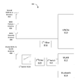
- FIG. 8 illustrates wireless communication device 800 including four tunable antennas to facilitate multimode communication that can support substantially all desired frequencies for a user equipment.
- the four tunable antennas include a first antenna 802 , a second antenna 804 , a third antenna 806 and a fourth antenna 808 .
- the four tunable antennas may be assigned to one or more RATs depending on the use and performance metrics of the radio technology.
- the first antenna 802 is shared between a wide area network (WAN) technologies (for example, LTE or 1x), the second antenna 804 may be a primary antenna for the wide area network, the third antenna 806 may be a secondary or diversity antenna for a wide area network and the fourth antenna 808 may be shared between multiple RATs such as a wireless local area network (WLAN), Bluetooth or WAN.
- WAN wide area network
- WLAN wireless local area network
- a radio technology chip (e.g., a transceiver chips) 810 of the wireless communication device 800 may be coupled to the antennas 802 , 804 , 806 and 808 .
- the radio technology chip 810 may be configured for WAN technology.
- a radio technology chip (e.g., a transceiver chips) 812 of the wireless communication device 800 may be coupled to the antenna 808 and may be configured for WLAN technology.
- a radio technology chip (e.g., a transceiver chip) 814 of the wireless communication device 800 may be coupled to the antenna 808 and may be configured for Bluetooth technology.
- the radio technology chips 812 and 814 may be integrated into a single chip.
- the configuration of the device 800 , antennas 802 , 804 , 806 , 808 , and the radio technology chips 810 , 812 and 814 supports a multiple-input and multiple-output (MIMO) carrier aggregation architecture.
- MIMO multiple-input and multiple-output
- the fourth antenna 808 may be coupled to a first switch 816 .
- the first switch 816 may be coupled to a first filter 818 and a second filter 820 .
- the first filter 818 may be coupled to the radio technology chip 810 .
- the antenna 808 is a WAN antenna
- the first filter 818 may filter WAN signals before passing the signals to the radio technology chip 810 .
- the second filter 820 may be coupled to the radio technology chip 812 and 814 via a second switch 822 .
- the second switch 822 may have a single input and multiple outputs. In one configuration, the second switch 822 may have two outputs to the radio technology chips 812 and 814 .
- LTE may be configured with two antennas (e.g., primary and diversity antennas 804 and 806 ). In other implementations, LTE may be configured with three antennas or four antennas depending on the functions of other radio technologies sharing the antennas of a user equipment. As noted, the third and fourth antennas 802 and 808 can be shared with other radio technologies such as WAN, WLAN and Bluetooth.
- LTE supports carrier aggregation where two downlink frequencies are received at the same time.
- user equipment may include up to four antennas, for LTE carrier aggregation mode two of the antennas are typically used in the implementation.
- the two antennas can be shared between two carrier frequencies associated with carrier aggregation mode.
- the carrier frequencies may be associated with four receive chains, with each carrier frequency supported by two receive chains. Therefore, a single antenna supports two receive chains on two carrier frequencies.
- the primary antenna 804 is a primary antenna for a first carrier frequency and a second carrier frequency
- the diversity antenna 806 is the diversity antenna for the first carrier frequency and the second carrier frequency. This configuration supports antenna diversity on both carrier frequencies, i.e., two antenna diversity on both carriers.
- a four receiver MIMO mode on a single frequency may be implemented by tuning the antennas and radio frequency (RF) chains to a same frequency.
- RF radio frequency
- a user equipment 120 having four tunable antennas may implement two different modes of operation, namely, carrier aggregation mode with two receive chains or four receiver MIMO mode on a single carrier frequency.
- carrier aggregation mode with two receive chains or four receiver MIMO mode on a single carrier frequency.
- other modes of operation may be implemented. For example, 2 ⁇ 3, i.e., three antennas and RF chains, on a primary carrier and 2 ⁇ 1, i.e., one antenna and RF chain, on a secondary carrier.
- Various features of the different modes of operation are described in U.S.
- An eNodeB scheduler (e.g., scheduler 644 ) may schedule the user equipment 120 for data transmission on the downlink and/or uplink based on a selected mode of operation for LTE. Selecting a particular mode of operation from the multiple LTE modes may be advantageous because it can improve the overall system capacity. In some implementations, the system capacity improvement is achieved by specifying a single carrier MIMO mode instead of carrier aggregation mode.
- an eNodeB has two antennas and there are two user equipments (UEs) in the system where each UE is capable of implementing carrier aggregation mode with two receive chains or four receiver MIMO mode on a single carrier frequency.
- each UE In the carrier aggregation mode, each UE is assigned half the bandwidth on the two carrier frequencies resulting in second order diversity. In the four receiver MIMO mode on a single carrier frequency, each UE is assigned the same total bandwidth and capability on the assigned bandwidth resulting in fourth order diversity. In this implementation, the total frequency resources assigned to each UE is the same. In this case, scheduling the two UEs on separate carriers achieves a capacity advantage over scheduling the two UEs according to carrier aggregation mode. However, in a single UE implementation, carrier aggregation is advantageous because of the increased bandwidth availability. When there is a mix of carrier aggregation mode only and carrier aggregation mode or four receiver MIMO mode on a single carrier frequency UEs, the second set of UEs may be scheduled according to a single carrier mode on one of the carriers.
- Whether a four receiver MIMO mode on a single carrier frequency or carrier aggregation mode is implemented depends on the eNodeB scheduler's knowledge of the UE's antenna capability during a communication connection. For example, the eNodeB scheduler 644 may know which UEs have two antenna capability or four antenna capability. Conventionally, one or more UE antenna capability indications may be sent to the eNodeB scheduler 644 at the start of a communication session. For conventional implementation, further indications of UE capability are not used, as UE antenna capability did not conventionally change during a duration of a communication connection.
- the UE antenna capability may change during the communication connection.
- antennas may be shared by different RATs dynamically during UE operation, resulting in switching of antennas between the different RATs.
- a user equipment may only have a two antenna capability on a particular RAT (for example, LTE).
- the UE may indicate to the eNodeB scheduler 644 at the start of the connection that the UE may only implement a mode of two receiver diversity on two carriers or carrier aggregation mode.
- two other antennas may become available to the UE for LTE communications.
- the antenna capability of the UE is changed to four receive antennas.
- the eNodeB would have no way of recognizing this change in the UE capability. It is desirable, therefore, to implement a method that provides an update of the UE antenna capability when an antenna becomes available or unavailable to the UE for a particular RAT after the start of the communication connection.
- a UE antenna capability may be updated during or after the start of the communication connection.
- This implementation includes dynamically sending an indication to a base station, such as an eNodeB, whenever the antenna capability of the UE changes after the start of the communication connection.
- the UE may dynamically indicate that it supports carrier aggregation mode with two receive chains or four receiver MIMO mode on a single carrier frequency during or after the start of the communication connection.
- the UEs indication of its antenna capability is dynamic and/or is subject to change throughout the duration of the communication connection.
- a UE antenna capability may be updated during or after the start of the communication connection based on modified measurement reports.
- the user equipment may be configured to bias a base station, such as an eNodeB, toward scheduling a carrier aggregation mode with two receive chains or four receiver MIMO mode on a single carrier frequency.
- a base station such as an eNodeB
- One method of implementing this feature is by modifying the channel quality indicator (CQI) reports of the UE.
- CQI channel quality indicator
- the UE sends CQI reports on both carriers.
- additional antennas become available (e.g., two additional antennas)
- the UE may modify the CQI on a second carrier frequency so that the UE may be scheduled on a first carrier (with four receive antennas) to improve the overall scheduling capacity.
- Other reports beyond CQI may be used. For instance, other reports including pre-coding matrix indicator (PMI) and rank indicator (RI) for LTE may be implemented according to certain aspects of the disclosure.
- the eNodeB When the UE is scheduled on the four receiver MIMO mode on a single carrier frequency, the eNodeB still expects CQI reports on the second carrier frequency. As a result, the UE may still send CQI reports on the second carrier frequency when the user equipment may have lost the carrier diversity capability due to its implementation of the four receiver MIMO mode on a single carrier frequency. In order to maintain the carrier diversity capability, the UE may report CQI measurements to the eNodeB based on two configurations. In one configuration, the UE continues to report a poor CQI on the second carrier in order to use the four receiver MIMO capability on a single carrier. In another configuration, the UE may periodically switch to carrier aggregation mode to allow for CQI measurements on the second carrier frequency.
- the UE may measure CQI of the second carrier before the loss of four receiver MIMO capability (due to loss of additional antennas) and report the CQI of both carriers to facilitate scheduling on both carriers.
- the CQI of the second carrier is measured right before the user equipment loses the four receiver MIMO capability.
- an apparatus such as a UE may dynamically generate an indication of a user equipment (UE) antenna capability during a communication connection, as shown in block 902 .
- the apparatus may send the indication to a base station, as shown in block 904 .
- UE user equipment
- FIG. 10 is a diagram illustrating an example of a hardware implementation for an apparatus 1000 employing a dynamic user equipment scheduling system 1014 .
- the dynamic user equipment scheduling system 1014 may be implemented with a bus architecture, represented generally by a bus 1024 .
- the bus 1024 may include any number of interconnecting buses and bridges depending on the specific application of the dynamic user equipment scheduling system 1014 and the overall design constraints.
- the bus 1024 links together various circuits including one or more processors and/or hardware modules, represented by a processor 1022 , an indication generating module 1002 and a sending module 1004 , and a computer-readable medium 1026 .
- the bus 1024 may also link various other circuits such as timing sources, peripherals, voltage regulators, and power management circuits, which are well known in the art, and therefore, will not be described any further.
- the apparatus includes the dynamic user equipment scheduling system 1014 coupled to a transceiver 1030 .
- the transceiver 1030 is coupled to one or more antennas 1020 .
- the transceiver 1030 provides a means for communicating with various other apparatus over a transmission medium.
- the dynamic user equipment scheduling system 1014 includes the processor 1022 coupled to the computer-readable medium 1026 .
- the processor 1022 is responsible for general processing, including the execution of software stored on the computer-readable medium 1026 .
- the software when executed by the processor 1022 , causes the dynamic user equipment scheduling system 1014 to perform the various functions described supra for any particular apparatus.
- the computer-readable medium 1026 may also be used for storing data that is manipulated by the processor 1022 when executing software.
- the dynamic user equipment scheduling system 1014 further includes the indication generating module 1002 for dynamically generating an indication of a user equipment antenna capability during a communication connection and the sending module 1004 for sending the indication to a base station.
- the indication generating module 1002 and the sending module 1004 may be software modules running in the processor 1022 , resident/stored in the computer readable medium 1026 , one or more hardware modules coupled to the processor 1022 , or some combination thereof.
- the dynamic user equipment scheduling system 1014 may be a component of the UE 120 and may include the memory 682 and/or the controller/processor 680 .
- the apparatus 1000 for wireless communication includes means for generating an indication.
- the means may be the UE 102 / 206 / 120 , controller/processor 680 , memory 682 , indication generating module 1002 and/or the dynamic user equipment scheduling system 1014 of the apparatus 1000 configured to perform the functions recited by the dynamic indication generating means.
- the dynamic user equipment scheduling system 1014 may be a component of the UE 120 and may include the memory 682 and/or the controller/processor 680 .
- the aforementioned means may be any module or any apparatus configured to perform the functions recited by the aforementioned means.
- the apparatus 1000 for wireless communication includes means for sending an indication.
- the means may be the UE 102 / 206 / 120 , the antenna 652 , transmit processor 664 , sending module 1004 and/or the dynamic user equipment scheduling system 1014 of the apparatus 1000 configured to perform the functions recited by the means.
- the dynamic user equipment scheduling system 1014 may be a component of the UE 120 and may include the memory 682 and/or the controller/processor 680 .
- the aforementioned means may be any module or any apparatus configured to perform the functions recited by the aforementioned means.
- an apparatus such as a base station, may receive an indication of a user equipment antenna capability during a communication connection, as shown in block 1102 .
- the apparatus may schedule the user equipment across carriers based at least in part on the indication, as shown in block 1104 .
- FIG. 12 is a diagram illustrating an example of a hardware implementation for an apparatus 1200 employing a dynamic user equipment scheduling system 1214 .
- the dynamic user equipment scheduling system 1214 may be implemented with a bus architecture, represented generally by a bus 1224 .
- the bus 1224 may include any number of interconnecting buses and bridges depending on the specific application of the dynamic user equipment scheduling system 1214 and the overall design constraints.
- the bus 1224 links together various circuits including one or more processors and/or hardware modules, represented by a processor 1222 , a receiving module 1202 and a scheduling module 1204 , and a computer-readable medium 1226 .
- the bus 1224 may also link various other circuits such as timing sources, peripherals, voltage regulators, and power management circuits, which are well known in the art, and therefore, will not be described any further.
- the apparatus includes the dynamic user equipment scheduling system 1214 coupled to a transceiver 1230 .
- the transceiver 1230 is coupled to one or more antennas 1220 .
- the transceiver 1230 provides a means for communicating with various other apparatus over a transmission medium.
- the dynamic user equipment scheduling system 1214 includes the processor 1222 coupled to the computer-readable medium 1226 .
- the processor 1222 is responsible for general processing, including the execution of software stored on the computer-readable medium 1226 .
- the software when executed by the processor 1222 , causes the dynamic user equipment scheduling system 1214 to perform the various functions described supra for any particular apparatus.
- the computer-readable medium 1226 may also be used for storing data that is manipulated by the processor 1222 when executing software.
- the dynamic user equipment scheduling system 1214 further includes the receiving module 1202 for receiving an indication of a user equipment antenna capability during a communication connection and the scheduling module 1204 for scheduling the user equipment across carriers based at least in part on the indication.
- the receiving 1202 and the scheduling module 1204 may be software modules running in the processor 1222 , resident/stored in the computer readable medium 1226 , one or more hardware modules coupled to the processor 1222 , or some combination thereof.
- the dynamic user equipment scheduling system 1214 may be a component of the eNodeB 110 and may include the memory 642 and/or the controller/processor 640 .
- the apparatus 1200 for wireless communication includes means for receiving.
- the means may be the eNodeB 110 , controller/processor 640 , memory 642 , receiving module 1202 and/or the dynamic user equipment scheduling system 1214 of the apparatus 1200 configured to perform the functions recited by the means.
- the dynamic user equipment scheduling system 1214 may be a component of the eNodeB 110 and may include the memory 642 and/or the controller/processor 640 .
- the aforementioned means may be any module or any apparatus configured to perform the functions recited by the aforementioned means.
- the apparatus 1200 for wireless communication includes means for scheduling.
- the means may be the eNodeB 110 , the antenna 634 , scheduler 644 , scheduling module 1204 and/or the dynamic user equipment scheduling system 1214 of the apparatus 1200 configured to perform the functions recited by the means.
- the dynamic user equipment scheduling system 1214 may be a component of the eNodeB 110 and may include the memory 642 and/or the controller/processor 640 .
- the aforementioned means may be any module or any apparatus configured to perform the functions recited by the aforementioned means.
- DSP digital signal processor
- ASIC application specific integrated circuit
- FPGA field programmable gate array
- a general-purpose processor may be a microprocessor, but in the alternative, the processor may be any conventional processor, controller, microcontroller, or state machine.
- a processor may also be implemented as a combination of computing devices, e.g., a combination of a DSP and a microprocessor, a plurality of microprocessors, one or more microprocessors in conjunction with a DSP core, or any other such configuration.
- a software module may reside in RAM memory, flash memory, ROM memory, EPROM memory, EEPROM memory, registers, hard disk, a removable disk, a CD-ROM, or any other form of storage medium known in the art.
- An exemplary storage medium is coupled to the processor such that the processor can read information from, and write information to, the storage medium.
- the storage medium may be integral to the processor.
- the processor and the storage medium may reside in an ASIC.
- the ASIC may reside in a user terminal.
- the processor and the storage medium may reside as discrete components in a user terminal.
- the functions described may be implemented in hardware, software, firmware, or any combination thereof. If implemented in software, the functions may be stored on or transmitted over as one or more instructions or code on a computer-readable medium.
- Computer-readable media includes both computer storage media and communication media including any medium that facilitates transfer of a computer program from one place to another.
- a storage media may be any available media that can be accessed by a general purpose or special purpose computer.
- such computer-readable media can comprise RAM, ROM, EEPROM, CD-ROM or other optical disk storage, magnetic disk storage or other magnetic storage devices, or any other medium that can be used to carry or store desired program code means in the form of instructions or data structures and that can be accessed by a general-purpose or special-purpose computer, or a general-purpose or special-purpose processor. Also, any connection is properly termed a computer-readable medium.
- Disk and disc includes compact disc (CD), laser disc, optical disc, digital versatile disc (DVD), floppy disk and blu-ray disc where disks usually reproduce data magnetically, while discs reproduce data optically with lasers. Combinations of the above should also be included within the scope of computer-readable media.
Abstract
A system capacity improvement is achieved by dynamically selecting a particular antenna mode of operation from the multiple radio access technology modes. In some implementations, the system capacity improvement is achieved by dynamically generating an indication of a user equipment (UE) antenna capability during a communication connection. The UE's indication of its antenna capability is dynamic and/or is subject to change throughout the duration of the communication connection. The indication may be sent to a base station.
Description
This application is related to U.S. patent application Ser. No. 13/411,467, filed Mar. 2, 2012, in the names of GUDEM et al., the disclosure of which is expressly incorporated by reference in its entirety. This application claims the benefit under 35 U.S.C. §119(e) to U.S. Provisional Patent Application No. 61/658,870, entitled, DYNAMIC UE SCHEDULING WITH SHARED ANTENNA AND CARRIER AGGREGATION, filed on Jun. 12, 2012, in the names of KADOUS, et al., the disclosure of which is expressly incorporated by reference herein in its entirety.
Field
Aspects of the present disclosure relate generally to wireless communication systems, and more particularly to dynamic user equipment scheduling with shared antennas and carrier aggregation in long term evolution.
Background
Wireless communication systems are widely deployed to provide various telecommunication services such as telephony, video, data, messaging, and broadcasts. Typical wireless communication systems may employ multiple-access technologies capable of supporting communication with multiple users by sharing available system resources (e.g., bandwidth, transmit power). Examples of such multiple-access technologies include code division multiple access (CDMA) systems, time division multiple access (TDMA) systems, frequency division multiple access (FDMA) systems, orthogonal frequency division multiple access (OFDMA) systems, single-carrier frequency divisional multiple access (SC-FDMA) systems, and time division synchronous code division multiple access (TD-SCDMA) systems.
These multiple access technologies have been adopted in various telecommunication standards to provide a common protocol that enables different wireless devices to communicate on a municipal, national, regional, and even global level. An example of an emerging telecommunication standard is Long Term Evolution (LTE). LTE is a set of enhancements to the Universal Mobile Telecommunications System (UMTS) mobile standard promulgated by Third Generation Partnership Project (3GPP). It is designed to better support mobile broadband Internet access by improving spectral efficiency, lower costs, improve services, make use of new spectrum, and better integrate with other open standards using OFDMA on the downlink (DL), SC-FDMA on the uplink (UL), and multiple-input multiple-output (MIMO) antenna technology. However, as the demand for mobile broadband access continues to increase, there exists a need for further improvements in LTE technology. Preferably, these improvements should be applicable to other multi-access technologies and the telecommunication standards that employ these technologies.
According to one aspect of the present disclosure, a method for wireless communication includes dynamically generating an indication of a user equipment antenna capability during a communication connection. The method may also include sending the indication to a base station.
According to another aspect of the present disclosure, an apparatus for wireless communication includes means for dynamically generating an indication of a user equipment antenna capability during a communication connection. The apparatus may also include means for sending the indication to a base station.
According to one aspect of the present disclosure, a computer program product for wireless communication in a wireless network includes a computer readable medium having non-transitory program code recorded thereon. The program code includes program code to dynamically generate an indication of a user equipment antenna capability during a communication connection. The program code also includes program code to send the indication to a base station.
According to one aspect of the present disclosure, an apparatus for wireless communication includes a memory and a processor(s) coupled to the memory. The processor(s) is configured to dynamically generate an indication of a user equipment antenna capability during a communication connection. The processor(s) is further configured to send the indication to a base station.
According to one aspect of the present disclosure, a method for wireless communication includes receiving an indication of a user equipment antenna capability during a communication connection. The method may also include scheduling the user equipment across one or more carriers based at least in part on the indication.
According to another aspect of the present disclosure, an apparatus for wireless communication includes means for receiving an indication of a user equipment antenna capability during a communication connection. The apparatus may also include means for scheduling the user equipment across one or more carriers based at least in part on the indication.
According to one aspect of the present disclosure, a computer program product for wireless communication in a wireless network includes a computer readable medium having non-transitory program code recorded thereon. The program code includes program code to receive an indication of a user equipment antenna capability during a communication connection. The program code also includes program code to schedule the user equipment across one or more carriers based at least in part on the indication.
According to one aspect of the present disclosure, an apparatus for wireless communication includes a memory and a processor(s) coupled to the memory. The processor(s) is configured to receive an indication of a user equipment antenna capability during a communication connection. The processor(s) is further configured to schedule the user equipment across one or more carriers based at least in part on the indication.
Additional features and advantages of the disclosure will be described below. It should be appreciated by those skilled in the art that this disclosure may be readily utilized as a basis for modifying or designing other structures for carrying out the same purposes of the present disclosure. It should also be realized by those skilled in the art that such equivalent constructions do not depart from the teachings of the disclosure as set forth in the appended claims. The novel features, which are believed to be characteristic of the disclosure, both as to its organization and method of operation, together with further objects and advantages, will be better understood from the following description when considered in connection with the accompanying figures. It is to be expressly understood, however, that each of the figures is provided for the purpose of illustration and description only and is not intended as a definition of the limits of the present disclosure.
The features, nature, and advantages of the present disclosure will become more apparent from the detailed description set forth below when taken in conjunction with the drawings in which like reference characters identify correspondingly throughout.
The detailed description set forth below, in connection with the appended drawings, is intended as a description of various configurations and is not intended to represent the only configurations in which the concepts described herein may be practiced. The detailed description includes specific details for the purpose of providing a thorough understanding of the various concepts. However, it will be apparent to those skilled in the art that these concepts may be practiced without these specific details. In some instances, well-known structures and components are shown in block diagram form in order to avoid obscuring such concepts.
Aspects of the telecommunication systems are presented with reference to various apparatus and methods. These apparatus and methods are described in the following detailed description and illustrated in the accompanying drawings by various blocks, modules, components, circuits, steps, processes, algorithms, etc. (collectively referred to as “elements”). These elements may be implemented using electronic hardware, computer software, or any combination thereof. Whether such elements are implemented as hardware or software depends upon the particular application and design constraints imposed on the overall system.
By way of example, an element, or any portion of an element, or any combination of elements may be implemented with a “processing system” that includes one or more processors. Examples of processors include microprocessors, microcontrollers, digital signal processors (DSPs), field programmable gate arrays (FPGAs), programmable logic devices (PLDs), state machines, gated logic, discrete hardware circuits, and other suitable hardware configured to perform the various functionality described throughout this disclosure. One or more processors in the processing system may execute software. Software shall be construed broadly to mean instructions, instruction sets, code, code segments, program code, programs, subprograms, software modules, applications, software applications, software packages, routines, subroutines, objects, executables, threads of execution, procedures, functions, etc., whether referred to as software, firmware, middleware, microcode, hardware description language, or otherwise.
Accordingly, in one or more exemplary embodiments, the functions described may be implemented in hardware, software, firmware, or any combination thereof. If implemented in software, the functions may be stored on or encoded as one or more instructions or code on a computer-readable medium. Computer-readable media includes computer storage media. Storage media may be any available media that can be accessed by a computer. By way of example, and not limitation, such computer-readable media can comprise RAM, ROM, EEPROM, CD-ROM or other optical disk storage, magnetic disk storage or other magnetic storage devices, or any other medium that can be used to carry or store desired program code in the form of instructions or data structures and that can be accessed by a computer. Disk and disc, as used herein, includes compact disc (CD), laser disc, optical disc, digital versatile disc (DVD), floppy disk and Blu-ray disc where disks usually reproduce data magnetically, while discs reproduce data optically with lasers. Combinations of the above should also be included within the scope of computer-readable media.
The E-UTRAN includes the evolved Node B (eNodeB) 106 and other eNodeBs 108. The eNodeB 106 provides user and control plane protocol terminations toward the UE 102. The eNodeB 106 may be connected to the other eNodeBs 108 via an X2 interface (e.g., backhaul). The eNodeB 106 may also be referred to as a base station, a base transceiver station, a radio base station, a radio transceiver, a transceiver function, a basic service set (BSS), an extended service set (ESS), or some other suitable terminology. The eNodeB 106 provides an access point to the EPC 111 for a UE 102. Examples of UEs 102 include a cellular phone, a smart phone, a session initiation protocol (SIP) phone, a laptop, a personal digital assistant (PDA), a satellite radio, a global positioning system, a multimedia device, a video device, a digital audio player (e.g., MP3 player), a camera, a game console, or any other similar functioning device. The UE 102 may also be referred to by those skilled in the art as a mobile station, a subscriber station, a mobile unit, a subscriber unit, a wireless unit, a remote unit, a mobile device, a wireless device, a wireless communications device, a remote device, a mobile subscriber station, an access terminal, a mobile terminal, a wireless terminal, a remote terminal, a handset, a user agent, a mobile client, a client, or some other suitable terminology.
The eNodeB 106 is connected by an S1 interface to the EPC 111. The EPC 111 includes a Mobility Management Entity (MME) 112, other MMEs 114, a Serving Gateway 116, and a Packet Data Network (PDN) Gateway 118. The MME 112 is the control node that processes the signaling between the UE 102 and the EPC 111. Generally, the MME 112 provides bearer and connection management. All user IP packets are transferred through the Serving Gateway 116, which itself is connected to the PDN Gateway 118. The PDN Gateway 118 provides UE IP address allocation as well as other functions. The PDN Gateway 118 is connected to the Operator's IP Services 122. The Operator's IP Services 122 may include the Internet, the Intranet, an IP Multimedia Subsystem (IMS), and a PS Streaming Service (PSS).
The modulation and multiple access scheme employed by the access network 200 may vary depending on the particular telecommunications standard being deployed. In LTE applications, OFDM is used on the downlink and SC-FDMA is used on the uplink to support both frequency division duplexing (FDD) and time division duplexing (TDD). As those skilled in the art will readily appreciate from the detailed description to follow, the various concepts presented herein are well suited for LTE applications. However, these concepts may be readily extended to other telecommunication standards employing other modulation and multiple access techniques. By way of example, these concepts may be extended to Evolution-Data Optimized (EV-DO) or Ultra Mobile Broadband (UMB). EV-DO and UMB are air interface standards promulgated by the 3rd Generation Partnership Project 2 (3GPP2) as part of the CDMA2000 family of standards and employs CDMA to provide broadband Internet access to mobile stations. These concepts may also be extended to Universal Terrestrial Radio Access (UTRA) employing Wideband-CDMA (W-CDMA) and other variants of CDMA, such as TD-SCDMA; Global System for Mobile Communications (GSM) employing TDMA; and Evolved UTRA (E-UTRA), Ultra Mobile Broadband (UMB), IEEE 802.11 (Wi-Fi), IEEE 802.16 (WiMAX), IEEE 802.20, and Flash-OFDM employing OFDMA. UTRA, E-UTRA, UMTS, LTE and GSM are described in documents from the 3GPP organization. CDMA2000 and UMB are described in documents from the 3GPP2 organization. The actual wireless communication standard and the multiple access technology employed will depend on the specific application and the overall design constraints imposed on the system.
The eNodeBs 204 may have multiple antennas supporting MIMO technology. The use of MIMO technology enables the eNodeBs 204 to exploit the spatial domain to support spatial multiplexing, beamforming, and transmit diversity. Spatial multiplexing may be used to transmit different streams of data simultaneously on the same frequency. The data steams may be transmitted to a single UE 206 to increase the data rate or to multiple UEs 206 to increase the overall system capacity. This is achieved by spatially precoding each data stream (i.e., applying a scaling of an amplitude and a phase) and then transmitting each spatially precoded stream through multiple transmit antennas on the downlink. The spatially precoded data streams arrive at the UE(s) 206 with different spatial signatures, which enables each of the UE(s) 206 to recover the one or more data streams destined for that UE 206. On the uplink, each UE 206 transmits a spatially precoded data stream, which enables the eNodeB 204 to identify the source of each spatially precoded data stream.
Spatial multiplexing is generally used when channel conditions are good. When channel conditions are less favorable, beamforming may be used to focus the transmission energy in one or more directions. This may be achieved by spatially precoding the data for transmission through multiple antennas. To achieve good coverage at the edges of the cell, a single stream beamforming transmission may be used in combination with transmit diversity.
In the detailed description that follows, various aspects of an access network will be described with reference to a MIMO system supporting OFDM on the downlink. OFDM is a spread-spectrum technique that modulates data over a number of subcarriers within an OFDM symbol. The subcarriers are spaced apart at precise frequencies. The spacing provides “orthogonality” that enables a receiver to recover the data from the subcarriers. In the time domain, a guard interval (e.g., cyclic prefix) may be added to each OFDM symbol to combat inter-OFDM-symbol interference. The uplink may use SC-FDMA in the form of a DFT-spread OFDM signal to compensate for high peak-to-average power ratio (PAPR).
A UE may be assigned resource blocks 410 a, 410 b in the control section to transmit control information to an eNodeB. The UE may also be assigned resource blocks 420 a, 420 b in the data section to transmit data to the eNodeB. The UE may transmit control information in a physical uplink control channel (PUCCH) on the assigned resource blocks in the control section. The UE may transmit only data or both data and control information in a physical uplink shared channel (PUSCH) on the assigned resource blocks in the data section. An uplink transmission may span both slots of a subframe and may hop across frequency.
A set of resource blocks may be used to perform initial system access and achieve uplink synchronization in a physical random access channel (PRACH) 430. The PRACH 430 carries a random sequence and cannot carry any uplink data/signaling. Each random access preamble occupies a bandwidth corresponding to six consecutive resource blocks. The starting frequency is specified by the network. That is, the transmission of the random access preamble is restricted to certain time and frequency resources. There is no frequency hopping for the PRACH. The PRACH attempt is carried in a single subframe (1 ms) or in a sequence of few contiguous subframes and a UE can make only a single PRACH attempt per frame (10 ms).
In the user plane, the L2 layer 508 includes a media access control (MAC) sublayer 510, a radio link control (RLC) sublayer 512, and a packet data convergence protocol (PDCP) 514 sublayer, which are terminated at the eNodeB on the network side. Although not shown, the UE may have several upper layers above the L2 layer 508 including a network layer (e.g., IP layer) that is terminated at the PDN gateway 118 on the network side, and an application layer that is terminated at the other end of the connection (e.g., far end UE, server, etc.).
The PDCP sublayer 514 provides multiplexing between different radio bearers and logical channels. The PDCP sublayer 514 also provides header compression for upper layer data packets to reduce radio transmission overhead, security by ciphering the data packets, and handover support for UEs between eNodeBs. The RLC sublayer 512 provides segmentation and reassembly of upper layer data packets, retransmission of lost data packets, and reordering of data packets to compensate for out-of-order reception due to hybrid automatic repeat request (HARQ). The MAC sublayer 510 provides multiplexing between logical and transport channels. The MAC sublayer 510 is also responsible for allocating the various radio resources (e.g., resource blocks) in one cell among the UEs. The MAC sublayer 510 is also responsible for HARQ operations.
In the control plane, the radio protocol architecture for the UE and eNodeB is substantially the same for the physical layer 506 and the L2 layer 508 with the exception that there is no header compression function for the control plane. The control plane also includes a radio resource control (RRC) sublayer 516 in Layer 3 (L3 layer). The RRC sublayer 516 is responsible for obtaining radio resources (i.e., radio bearers) and for configuring the lower layers using RRC signaling between the eNodeB and the UE.
At the base station 110, a transmit processor 620 may receive data from a data source 612 and control information from a controller/processor 640. The control information may be for the PBCH, PCFICH, PHICH, PDCCH, etc. The data may be for the PDSCH, etc. The processor 620 may process (e.g., encode and symbol map) the data and control information to obtain data symbols and control symbols, respectively. The processor 620 may also generate reference symbols, e.g., for the PSS, SSS, and cell-specific reference signal. A transmit (TX) multiple-input multiple-output (MIMO) processor 630 may perform spatial processing (e.g., precoding) on the data symbols, the control symbols, and/or the reference symbols, if applicable, and may provide output symbol streams to the modulators (MODs) 632 a through 632 t. Each modulator 632 may process a respective output symbol stream (e.g., for OFDM, etc.) to obtain an output sample stream. Each modulator 632 may further process (e.g., convert to analog, amplify, filter, and upconvert) the output sample stream to obtain a downlink signal. Downlink signals from modulators 632 a through 632 t may be transmitted via the antennas 634 a through 634 t, respectively.
At the UE 120, the antennas 652 a through 652 r may receive the downlink signals from the base station 110 and may provide received signals to the demodulators (DEMODs) 654 a through 654 r, respectively. Each demodulator 654 may condition (e.g., filter, amplify, downconvert, and digitize) a respective received signal to obtain input samples. Each demodulator 654 may further process the input samples (e.g., for OFDM, etc.) to obtain received symbols. A MIMO detector 656 may obtain received symbols from all the demodulators 654 a through 654 r, perform MIMO detection on the received symbols if applicable, and provide detected symbols. A receive processor 658 may process (e.g., demodulate, deinterleave, and decode) the detected symbols, provide decoded data for the UE 120 to a data sink 660, and provide decoded control information to a controller/processor 680.
On the uplink, at the UE 120, a transmit processor 664 may receive and process data (e.g., for the PUSCH) from a data source 662 and control information (e.g., for the PUCCH) from the controller/processor 680. The processor 664 may also generate reference symbols for a reference signal. The symbols from the transmit processor 664 may be precoded by a TX MIMO processor 666 if applicable, further processed by the modulators 654 a through 654 r (e.g., for SC-FDM, etc.), and transmitted to the base station 110. At the base station 110, the uplink signals from the UE 120 may be received by the antennas 634, processed by the demodulators 632, detected by a MIMO detector 636 if applicable, and further processed by a receive processor 638 to obtain decoded data and control information sent by the UE 120. The processor 638 may provide the decoded data to a data sink 639 and the decoded control information to the controller/processor 640. The base station 110 can send messages to other base stations, for example, over an X2 interface 641.
The controllers/ processors 640 and 680 may direct the operation at the base station 110 and the UE 120, respectively. The processor 640/680 and/or other processors and modules at the base station 110/UE 120 may perform or direct the execution of the functional blocks illustrated in FIG. 9 , and/or other processes for the techniques described herein. The memories 642 and 682 may store data and program codes for the base station 110 and the UE 120, respectively. A scheduler 644 may schedule UEs for data transmission on the downlink and/or uplink.
LTE-Advanced UEs use spectrum in up to 20 MHz bandwidths allocated in a carrier aggregation of up to a total of 100 MHz (5 component carriers) used for transmission in each direction. Generally, less traffic is transmitted on the uplink than the downlink, so the uplink spectrum allocation may be smaller than the downlink allocation. For example, if 20 MHz is assigned to the uplink, the downlink may be assigned 100 MHz. These asymmetric FDD assignments will conserve spectrum and are a good fit for the typically asymmetric bandwidth utilization by broadband subscribers.
For the LTE-Advanced mobile systems, two types of carrier aggregation (CA) methods have been proposed, continuous CA and non-continuous CA. They are illustrated in FIGS. 7A and 7B . Non-continuous CA occurs when multiple available component carriers are separated along the frequency band (FIG. 7B ). On the other hand, continuous CA occurs when multiple available component carriers are adjacent to each other (FIG. 7A ). Both non-continuous and continuous CA aggregate multiple LTE/component carriers to serve a single unit of LTE Advanced UE.
Multiple RF receiving units and multiple FFTs may be deployed with non-continuous CA in LTE-Advanced UE since the carriers are separated along the frequency band. Because non-continuous CA supports data transmissions over multiple separated carriers across a large frequency range, propagation path loss, Doppler shift and other radio channel characteristics may vary a lot at different frequency bands.
Thus, to support broadband data transmission under the non-continuous CA approach, methods may be used to adaptively adjust coding, modulation and transmission power for different component carriers. For example, in an LTE-Advanced system where the enhanced NodeB (eNodeB) has fixed transmitting power on each component carrier, the effective coverage or supportable modulation and coding of each component carrier may be different.
Dynamic User Equipment Scheduling with Shared Antennas and Carrier Aggregation
A wireless communication device may include a number of radio access technologies (RATs) to support communication with different wireless networks. For example, the radio technologies may include a wide area network (e.g., third generation partnership project (3GPP) long term evolution (LTE) or 1x radio transmission technology (1X)), wireless local area network (WLAN), Bluetooth and/or the like. Multiple antennas and/or receivers/transmitters may be provided to facilitate multimode communication with various combinations of antenna and receiver/transmitter configurations. Each radio technology may transmit or receive signals via one or more antennas. The number of antennas on a wireless communication device (e.g., user equipment) may be limited due to space/cost constraints and coupling issues. As a result, it is desirable to support all radio technologies on the wireless communication device with a limited number of antennas such that desired performance may be achieved.
A radio technology chip (e.g., a transceiver chips) 810 of the wireless communication device 800 may be coupled to the antennas 802, 804, 806 and 808. The radio technology chip 810 may be configured for WAN technology. A radio technology chip (e.g., a transceiver chips) 812 of the wireless communication device 800 may be coupled to the antenna 808 and may be configured for WLAN technology. A radio technology chip (e.g., a transceiver chip) 814 of the wireless communication device 800 may be coupled to the antenna 808 and may be configured for Bluetooth technology. The radio technology chips 812 and 814 may be integrated into a single chip. The configuration of the device 800, antennas 802, 804, 806, 808, and the radio technology chips 810, 812 and 814 supports a multiple-input and multiple-output (MIMO) carrier aggregation architecture.
The fourth antenna 808 may be coupled to a first switch 816. The first switch 816 may be coupled to a first filter 818 and a second filter 820. The first filter 818 may be coupled to the radio technology chip 810. When the antenna 808 is a WAN antenna, the first filter 818 may filter WAN signals before passing the signals to the radio technology chip 810. The second filter 820 may be coupled to the radio technology chip 812 and 814 via a second switch 822. The second switch 822 may have a single input and multiple outputs. In one configuration, the second switch 822 may have two outputs to the radio technology chips 812 and 814.
In some implementations, LTE may be configured with two antennas (e.g., primary and diversity antennas 804 and 806). In other implementations, LTE may be configured with three antennas or four antennas depending on the functions of other radio technologies sharing the antennas of a user equipment. As noted, the third and fourth antennas 802 and 808 can be shared with other radio technologies such as WAN, WLAN and Bluetooth.
LTE supports carrier aggregation where two downlink frequencies are received at the same time. Although user equipment may include up to four antennas, for LTE carrier aggregation mode two of the antennas are typically used in the implementation. The two antennas can be shared between two carrier frequencies associated with carrier aggregation mode. The carrier frequencies may be associated with four receive chains, with each carrier frequency supported by two receive chains. Therefore, a single antenna supports two receive chains on two carrier frequencies. For example, in the two antenna configuration, the primary antenna 804 is a primary antenna for a first carrier frequency and a second carrier frequency and the diversity antenna 806 is the diversity antenna for the first carrier frequency and the second carrier frequency. This configuration supports antenna diversity on both carrier frequencies, i.e., two antenna diversity on both carriers.
When two additional antennas, for example, are available to a user equipment 120, a four receiver MIMO mode on a single frequency may be implemented by tuning the antennas and radio frequency (RF) chains to a same frequency. Thus, a user equipment 120 having four tunable antennas may implement two different modes of operation, namely, carrier aggregation mode with two receive chains or four receiver MIMO mode on a single carrier frequency. Although only two modes of operation are described, other modes of operation may be implemented. For example, 2×3, i.e., three antennas and RF chains, on a primary carrier and 2×1, i.e., one antenna and RF chain, on a secondary carrier. Various features of the different modes of operation are described in U.S. patent application Ser. No. 13/411,467, filed Mar. 2, 2012, in the names of GUDEM et al., the disclosure of which is expressly incorporated by reference in its entirety.
One aspect of the present disclosure includes dynamically switching between multiple modes of operation for LTE. An eNodeB scheduler (e.g., scheduler 644) may schedule the user equipment 120 for data transmission on the downlink and/or uplink based on a selected mode of operation for LTE. Selecting a particular mode of operation from the multiple LTE modes may be advantageous because it can improve the overall system capacity. In some implementations, the system capacity improvement is achieved by specifying a single carrier MIMO mode instead of carrier aggregation mode. In one example, an eNodeB has two antennas and there are two user equipments (UEs) in the system where each UE is capable of implementing carrier aggregation mode with two receive chains or four receiver MIMO mode on a single carrier frequency. In the carrier aggregation mode, each UE is assigned half the bandwidth on the two carrier frequencies resulting in second order diversity. In the four receiver MIMO mode on a single carrier frequency, each UE is assigned the same total bandwidth and capability on the assigned bandwidth resulting in fourth order diversity. In this implementation, the total frequency resources assigned to each UE is the same. In this case, scheduling the two UEs on separate carriers achieves a capacity advantage over scheduling the two UEs according to carrier aggregation mode. However, in a single UE implementation, carrier aggregation is advantageous because of the increased bandwidth availability. When there is a mix of carrier aggregation mode only and carrier aggregation mode or four receiver MIMO mode on a single carrier frequency UEs, the second set of UEs may be scheduled according to a single carrier mode on one of the carriers.
Whether a four receiver MIMO mode on a single carrier frequency or carrier aggregation mode is implemented depends on the eNodeB scheduler's knowledge of the UE's antenna capability during a communication connection. For example, the eNodeB scheduler 644 may know which UEs have two antenna capability or four antenna capability. Conventionally, one or more UE antenna capability indications may be sent to the eNodeB scheduler 644 at the start of a communication session. For conventional implementation, further indications of UE capability are not used, as UE antenna capability did not conventionally change during a duration of a communication connection.
With antenna sharing, however, the UE antenna capability may change during the communication connection. In particular, antennas may be shared by different RATs dynamically during UE operation, resulting in switching of antennas between the different RATs. For example, at the start of a connection, a user equipment may only have a two antenna capability on a particular RAT (for example, LTE). Accordingly, the UE may indicate to the eNodeB scheduler 644 at the start of the connection that the UE may only implement a mode of two receiver diversity on two carriers or carrier aggregation mode. During the communication connection, however, two other antennas may become available to the UE for LTE communications. At this point, the antenna capability of the UE is changed to four receive antennas. Presently, the eNodeB would have no way of recognizing this change in the UE capability. It is desirable, therefore, to implement a method that provides an update of the UE antenna capability when an antenna becomes available or unavailable to the UE for a particular RAT after the start of the communication connection.
In one aspect of the present disclosure, a UE antenna capability may be updated during or after the start of the communication connection. This implementation includes dynamically sending an indication to a base station, such as an eNodeB, whenever the antenna capability of the UE changes after the start of the communication connection. In one aspect of the disclosure, the UE may dynamically indicate that it supports carrier aggregation mode with two receive chains or four receiver MIMO mode on a single carrier frequency during or after the start of the communication connection. Thus, the UEs indication of its antenna capability is dynamic and/or is subject to change throughout the duration of the communication connection.
In one aspect of the disclosure, a UE antenna capability may be updated during or after the start of the communication connection based on modified measurement reports. In this aspect, the user equipment may be configured to bias a base station, such as an eNodeB, toward scheduling a carrier aggregation mode with two receive chains or four receiver MIMO mode on a single carrier frequency. One method of implementing this feature is by modifying the channel quality indicator (CQI) reports of the UE. In the carrier aggregation mode, the UE sends CQI reports on both carriers. When additional antennas become available (e.g., two additional antennas) the UE may modify the CQI on a second carrier frequency so that the UE may be scheduled on a first carrier (with four receive antennas) to improve the overall scheduling capacity. Other reports beyond CQI may be used. For instance, other reports including pre-coding matrix indicator (PMI) and rank indicator (RI) for LTE may be implemented according to certain aspects of the disclosure.
When the UE is scheduled on the four receiver MIMO mode on a single carrier frequency, the eNodeB still expects CQI reports on the second carrier frequency. As a result, the UE may still send CQI reports on the second carrier frequency when the user equipment may have lost the carrier diversity capability due to its implementation of the four receiver MIMO mode on a single carrier frequency. In order to maintain the carrier diversity capability, the UE may report CQI measurements to the eNodeB based on two configurations. In one configuration, the UE continues to report a poor CQI on the second carrier in order to use the four receiver MIMO capability on a single carrier. In another configuration, the UE may periodically switch to carrier aggregation mode to allow for CQI measurements on the second carrier frequency. For example, the UE may measure CQI of the second carrier before the loss of four receiver MIMO capability (due to loss of additional antennas) and report the CQI of both carriers to facilitate scheduling on both carriers. In one aspect, the CQI of the second carrier is measured right before the user equipment loses the four receiver MIMO capability.
As shown in FIG. 9 , an apparatus, such as a UE, may dynamically generate an indication of a user equipment (UE) antenna capability during a communication connection, as shown in block 902. The apparatus may send the indication to a base station, as shown in block 904.
The apparatus includes the dynamic user equipment scheduling system 1014 coupled to a transceiver 1030. The transceiver 1030 is coupled to one or more antennas 1020. The transceiver 1030 provides a means for communicating with various other apparatus over a transmission medium. The dynamic user equipment scheduling system 1014 includes the processor 1022 coupled to the computer-readable medium 1026. The processor 1022 is responsible for general processing, including the execution of software stored on the computer-readable medium 1026. The software, when executed by the processor 1022, causes the dynamic user equipment scheduling system 1014 to perform the various functions described supra for any particular apparatus. The computer-readable medium 1026 may also be used for storing data that is manipulated by the processor 1022 when executing software. The dynamic user equipment scheduling system 1014 further includes the indication generating module 1002 for dynamically generating an indication of a user equipment antenna capability during a communication connection and the sending module 1004 for sending the indication to a base station. The indication generating module 1002 and the sending module 1004 may be software modules running in the processor 1022, resident/stored in the computer readable medium 1026, one or more hardware modules coupled to the processor 1022, or some combination thereof. The dynamic user equipment scheduling system 1014 may be a component of the UE 120 and may include the memory 682 and/or the controller/processor 680.
In one configuration, the apparatus 1000 for wireless communication includes means for generating an indication. The means may be the UE 102/206/120, controller/processor 680, memory 682, indication generating module 1002 and/or the dynamic user equipment scheduling system 1014 of the apparatus 1000 configured to perform the functions recited by the dynamic indication generating means. As described above, the dynamic user equipment scheduling system 1014 may be a component of the UE 120 and may include the memory 682 and/or the controller/processor 680. In another aspect, the aforementioned means may be any module or any apparatus configured to perform the functions recited by the aforementioned means.
In one configuration, the apparatus 1000 for wireless communication includes means for sending an indication. The means may be the UE 102/206/120, the antenna 652, transmit processor 664, sending module 1004 and/or the dynamic user equipment scheduling system 1014 of the apparatus 1000 configured to perform the functions recited by the means. As described above, the dynamic user equipment scheduling system 1014 may be a component of the UE 120 and may include the memory 682 and/or the controller/processor 680. In another aspect, the aforementioned means may be any module or any apparatus configured to perform the functions recited by the aforementioned means.
As shown in FIG. 11 an apparatus, such as a base station, may receive an indication of a user equipment antenna capability during a communication connection, as shown in block 1102. The apparatus may schedule the user equipment across carriers based at least in part on the indication, as shown in block 1104.
The apparatus includes the dynamic user equipment scheduling system 1214 coupled to a transceiver 1230. The transceiver 1230 is coupled to one or more antennas 1220. The transceiver 1230 provides a means for communicating with various other apparatus over a transmission medium. The dynamic user equipment scheduling system 1214 includes the processor 1222 coupled to the computer-readable medium 1226. The processor 1222 is responsible for general processing, including the execution of software stored on the computer-readable medium 1226. The software, when executed by the processor 1222, causes the dynamic user equipment scheduling system 1214 to perform the various functions described supra for any particular apparatus. The computer-readable medium 1226 may also be used for storing data that is manipulated by the processor 1222 when executing software. The dynamic user equipment scheduling system 1214 further includes the receiving module 1202 for receiving an indication of a user equipment antenna capability during a communication connection and the scheduling module 1204 for scheduling the user equipment across carriers based at least in part on the indication. The receiving 1202 and the scheduling module 1204 may be software modules running in the processor 1222, resident/stored in the computer readable medium 1226, one or more hardware modules coupled to the processor 1222, or some combination thereof. The dynamic user equipment scheduling system 1214 may be a component of the eNodeB 110 and may include the memory 642 and/or the controller/processor 640.
In one configuration, the apparatus 1200 for wireless communication includes means for receiving. The means may be the eNodeB 110, controller/processor 640, memory 642, receiving module 1202 and/or the dynamic user equipment scheduling system 1214 of the apparatus 1200 configured to perform the functions recited by the means. As described above, the dynamic user equipment scheduling system 1214 may be a component of the eNodeB 110 and may include the memory 642 and/or the controller/processor 640. In another aspect, the aforementioned means may be any module or any apparatus configured to perform the functions recited by the aforementioned means.
In one configuration, the apparatus 1200 for wireless communication includes means for scheduling. The means may be the eNodeB 110, the antenna 634, scheduler 644, scheduling module 1204 and/or the dynamic user equipment scheduling system 1214 of the apparatus 1200 configured to perform the functions recited by the means. As described above, the dynamic user equipment scheduling system 1214 may be a component of the eNodeB 110 and may include the memory 642 and/or the controller/processor 640. In another aspect, the aforementioned means may be any module or any apparatus configured to perform the functions recited by the aforementioned means.
Those of skill would further appreciate that the various illustrative logical blocks, modules, circuits, and algorithm steps described in connection with the disclosure herein may be implemented as electronic hardware, computer software, or combinations of both. To clearly illustrate this interchangeability of hardware and software, various illustrative components, blocks, modules, circuits, and steps have been described above generally in terms of their functionality. Whether such functionality is implemented as hardware or software depends upon the particular application and design constraints imposed on the overall system. Skilled artisans may implement the described functionality in varying ways for each particular application, but such implementation decisions should not be interpreted as causing a departure from the scope of the present disclosure.
The various illustrative logical blocks, modules, and circuits described in connection with the disclosure herein may be implemented or performed with a general-purpose processor, a digital signal processor (DSP), an application specific integrated circuit (ASIC), a field programmable gate array (FPGA) or other programmable logic device, discrete gate or transistor logic, discrete hardware components, or any combination thereof designed to perform the functions described herein. A general-purpose processor may be a microprocessor, but in the alternative, the processor may be any conventional processor, controller, microcontroller, or state machine. A processor may also be implemented as a combination of computing devices, e.g., a combination of a DSP and a microprocessor, a plurality of microprocessors, one or more microprocessors in conjunction with a DSP core, or any other such configuration.
The steps of a method or algorithm described in connection with the disclosure herein may be embodied directly in hardware, in a software module executed by a processor, or in a combination of the two. A software module may reside in RAM memory, flash memory, ROM memory, EPROM memory, EEPROM memory, registers, hard disk, a removable disk, a CD-ROM, or any other form of storage medium known in the art. An exemplary storage medium is coupled to the processor such that the processor can read information from, and write information to, the storage medium. In the alternative, the storage medium may be integral to the processor. The processor and the storage medium may reside in an ASIC. The ASIC may reside in a user terminal. In the alternative, the processor and the storage medium may reside as discrete components in a user terminal.
In one or more exemplary designs, the functions described may be implemented in hardware, software, firmware, or any combination thereof. If implemented in software, the functions may be stored on or transmitted over as one or more instructions or code on a computer-readable medium. Computer-readable media includes both computer storage media and communication media including any medium that facilitates transfer of a computer program from one place to another. A storage media may be any available media that can be accessed by a general purpose or special purpose computer. By way of example, and not limitation, such computer-readable media can comprise RAM, ROM, EEPROM, CD-ROM or other optical disk storage, magnetic disk storage or other magnetic storage devices, or any other medium that can be used to carry or store desired program code means in the form of instructions or data structures and that can be accessed by a general-purpose or special-purpose computer, or a general-purpose or special-purpose processor. Also, any connection is properly termed a computer-readable medium. For example, if the software is transmitted from a website, server, or other remote source using a coaxial cable, fiber optic cable, twisted pair, digital subscriber line (DSL), or wireless technologies such as infrared, radio, and microwave, then the coaxial cable, fiber optic cable, twisted pair, DSL, or wireless technologies such as infrared, radio, and microwave are included in the definition of medium. Disk and disc, as used herein, includes compact disc (CD), laser disc, optical disc, digital versatile disc (DVD), floppy disk and blu-ray disc where disks usually reproduce data magnetically, while discs reproduce data optically with lasers. Combinations of the above should also be included within the scope of computer-readable media.
The previous description of the disclosure is provided to enable any person skilled in the art to make or use the disclosure. Various modifications to the disclosure will be readily apparent to those skilled in the art, and the generic principles defined herein may be applied to other variations without departing from the spirit or scope of the disclosure. Thus, the disclosure is not intended to be limited to the examples and designs described herein but is to be accorded the widest scope consistent with the principles and novel features disclosed herein.
Claims (20)
1. A method of wireless communication, comprising:
dynamically updating a user equipment (UE) receive antenna availability for a specific radio access technology (RAT) when a receive antenna, of multiple antennas, for downlink communication for the specific RAT of the UE becomes available or unavailable to the UE after a start of a communication connection, the receive antenna capable of switching between different RATs, the updating based at least in part on a change in a number of receive antennas available for the specific RAT;
dynamically generating an indication of the updated UE antenna capability for the specific RAT after the start of the communication connection by dynamically generating a modified UE communications report to bias a base station scheduling toward at least one of a single carrier frequency mode or a carrier aggregation mode, wherein the single carrier frequency mode has more receive antennas for the downlink communication than the carrier aggregation mode;
sending the indication to the base station to reschedule the UE for communication in accordance with the updated UE receive antenna availability; and
communicating based at least in part on the rescheduling.
2. The method of claim 1 , further comprising periodically switching to a carrier aggregation mode to allow for channel quality indicator measurements on a second carrier frequency when the UE is scheduled on a single carrier frequency.
3. The method of claim 1 , further comprising operating in at least one of single carrier frequency mode or carrier aggregation mode based on the indication.
4. The method of claim 1 , further comprising wirelessly communicating over a long term evolution network.
5. An apparatus for wireless communication, comprising:
means for dynamically updating a user equipment (UE) receive antenna availability for a specific radio access technology (RAT) when a receive antenna, of multiple antennas, for downlink communication for the specific RAT of the UE becomes available or unavailable to the UE after a start of a communication connection, the receive antenna capable of switching between different RATs, the updating based at least in part on a change in a number of receive antennas available for the specific RAT;
means for dynamically generating an indication of the updated UE antenna capability for the specific RAT after the start of the communication connection by dynamically generating a modified UE communications report to bias a base station scheduling toward at least one of a single carrier frequency mode or a carrier aggregation mode, wherein the single carrier frequency mode has more receive antennas for the downlink communication than the carrier aggregation mode;
means for sending the indication to the base station to reschedule the UE for communication in accordance with the updated UE receive antenna availability; and
means for communicating based at least in part on the rescheduling.
6. The apparatus of claim 5 , further comprising means for periodically switching to the carrier aggregation mode to allow for channel quality indicator measurements on a second carrier frequency when the UE is schedule on a single carrier frequency.
7. The apparatus of claim 5 , further comprising means for operating in at least one of single carrier frequency mode or carrier aggregation mode based on the indication.
8. An apparatus for wireless communication, comprising:
a memory; and
at least one processor coupled to the memory and configured:
to dynamically update a user equipment (UE) receive antenna availability for a specific radio access technology (RAT) when a receive antenna, of multiple antennas, for downlink communication for the specific RAT of the UE becomes available or unavailable to the UE after a start of a communication connection, the receive antenna capable of switching between different RATs, the updating based at least in part on a change in a number of receive antennas available for the specific RAT;
to dynamically generate an indication of the updated UE receive antenna availability for the specific RAT after the start of the communication connection by dynamically generating a modified UE communications report to bias a base station scheduling toward at least one of a single carrier frequency mode or a carrier aggregation mode, wherein the single carrier frequency mode has more receive antennas for the downlink communication than the carrier aggregation mode;
to send the indication to a base station to reschedule the UE for communication in accordance with the updated UE receive antenna availability; and
to communicate based at least in part on the rescheduling.
9. The apparatus of claim 8 , in which the at least one processor is further configured to periodically switch to a carrier aggregation mode to allow for channel quality indicator measurements on a second carrier frequency when the UE is scheduled on a single carrier frequency.
10. The apparatus of claim 8 , in which the at least one processor is further configured to operate in at least one of single carrier frequency mode or carrier aggregation mode based on the indication.
11. The apparatus of claim 8 , in which the at least one processor is further configured to wirelessly communicate over a long term evolution network.
12. A non-transitory computer-readable medium having non-transitory program code recorded thereon, the program code comprising:
program code to dynamically update a user equipment (UE) receive antenna availability for a specific radio access technology (RAT) when a receive antenna, of multiple antennas, for downlink communication for the specific RAT of the UE becomes available or unavailable to the UE after a start of a communication connection, the receive antenna capable of switching between different RATs, the updating based at least in part on a change in a number of receive antennas available for the specific RAT;
program code to dynamically generate an indication of the updated UE receive antenna availability for the specific RAT during the communication connection including dynamically generating a modified UE communications report to bias a base station scheduling toward at least one of a single carrier frequency mode or a carrier aggregation mode, wherein the single carrier frequency mode has more receive antennas for the downlink communication than the carrier aggregation mode;
program code to send the indication to the base station to reschedule the UE for communication in accordance with the updated UE receive antenna availability; and
program code to communicate based at least in part on the rescheduling.
13. The non-transitory computer-readable medium of claim 12 , in which the program code is further configured to periodically switch to the carrier aggregation mode to allow for channel quality indicator measurements on a second carrier frequency mode when the UE is schedule on a single carrier frequency.
14. The non-transitory computer-readable medium of claim 12 , in which the program code is further configured to operate in at least one of single carrier frequency mode or carrier aggregation mode based on the indication.
15. A method of wireless communication, comprising:
receiving an indication of a user equipment (UE) receive antenna availability for a specific radio access technology (RAT) when a receive antenna, of multiple antennas, for downlink communication for the specific RAT of the UE becomes available or unavailable to the UE after a start of a communication connection, the receive antenna capable of switching between different RATs, the indication including a modified UE communications report to bias a base station scheduling toward at least one of a single carrier frequency mode or a carrier aggregation mode, wherein the single carrier frequency mode has more receive antennas for the downlink communication than the carrier aggregation mode, the updated UE receive antenna availability based at least in part on a change in a number of receive antennas available for the specific RAT; and
rescheduling the UE across one or more carriers based at least in part on the indication.
16. The method of claim 15 , further comprising wirelessly communicating over a long term evolution network.
17. An apparatus for wireless communication, comprising:
means for receiving an indication of an updated (UE) receive antenna availability for a specific radio access technology (RAT) when a receive antenna, of multiple antennas, for downlink communication for the specific RAT of the UE becomes available or unavailable to the UE after a start of a communication connection, the receive antenna capable of switching between different RATs, the indication including a modified UE communications report to bias a base station scheduling toward at least one of a single carrier frequency mode or a carrier aggregation mode, wherein the single carrier frequency mode has more receive antennas for the downlink communication than the carrier aggregation mode, the updated UE receive antenna availability based at least in part on a change in a number of receive antennas available for the specific RAT; and
means for rescheduling the UE across one or more carriers based at least in part on the indication.
18. An apparatus for wireless communication, comprising:
a memory; and
at least one processor coupled to the memory and configured:
to receive an indication of an updated user equipment (UE) receive antenna availability for a specific radio access technology (RAT) when a receive antenna, of multiple antennas, for downlink communication for the specific RAT of the UE becomes available or unavailable to the UE after a start of a communication connection, the receive antenna capable of switching between different RATs, the indication including a modified UE communications repot to bias a base station scheduling toward at least one of a single carrier frequency mode or a carrier aggregation mode, wherein the single carrier frequency mode has more receive antennas for the downlink communication than the carrier aggregation mode, the updated UE receive antenna availability based at least in part on a change in a number of receive antennas available for the specific RAT; and
to reschedule the UE across one or more carriers based at least in part on the indication.
19. The apparatus of claim 18 , in which the at least one processor is further configured to wirelessly communicate over a long term evolution network.
20. A non-transitory computer-readable medium having non-transitory program code recorded thereon, the program code comprising:
program code to receive an indication of an updated user equipment (UE) receive antenna availability for a specific radio access technology (RAT) when a receive antenna, of multiple antennas, for downlink communication for the specific RAT of the UE becomes available or unavailable to the UE after a start of a communication connection, the receive antenna capable of switching between different RATs, the indication including a modified UE communication report to bias a base station scheduling toward at least one of a single carrier frequency mode or a carrier aggregation mode, wherein the single carrier frequency mode has more receive antennas for the downlink communication than the carrier aggregation mode, the updated UE antenna capability based at least in part on a change in a number of receive antennas available for the specific RAT; and
program code to reschedule the UE across one or more carriers based at least in part on the indication.
Priority Applications (6)
| Application Number | Priority Date | Filing Date | Title |
|---|---|---|---|
| US13/915,389 US9867194B2 (en) | 2012-06-12 | 2013-06-11 | Dynamic UE scheduling with shared antenna and carrier aggregation |
| CN201380030548.4A CN104365031B (en) | 2012-06-12 | 2013-06-12 | The dynamic uplink dispatching method and device being polymerize using shared antenna and carrier wave |
| EP13733160.9A EP2859665B1 (en) | 2012-06-12 | 2013-06-12 | Dynamic uplink scheduling with shared antenna and carrier aggregation |
| KR1020157000583A KR101927964B1 (en) | 2012-06-12 | 2013-06-12 | Dynamic uplink scheduling with shared antenna and carrier aggregation |
| PCT/US2013/045461 WO2013188561A1 (en) | 2012-06-12 | 2013-06-12 | Dynamic uplink scheduling with shared antenna and carrier aggregation |
| IN2354MUN2014 IN2014MN02354A (en) | 2012-06-12 | 2014-11-19 |
Applications Claiming Priority (2)
| Application Number | Priority Date | Filing Date | Title |
|---|---|---|---|
| US201261658870P | 2012-06-12 | 2012-06-12 | |
| US13/915,389 US9867194B2 (en) | 2012-06-12 | 2013-06-11 | Dynamic UE scheduling with shared antenna and carrier aggregation |
Publications (2)
| Publication Number | Publication Date |
|---|---|
| US20130329665A1 US20130329665A1 (en) | 2013-12-12 |
| US9867194B2 true US9867194B2 (en) | 2018-01-09 |
Family
ID=49715263
Family Applications (1)
| Application Number | Title | Priority Date | Filing Date |
|---|---|---|---|
| US13/915,389 Active 2034-01-31 US9867194B2 (en) | 2012-06-12 | 2013-06-11 | Dynamic UE scheduling with shared antenna and carrier aggregation |
Country Status (6)
| Country | Link |
|---|---|
| US (1) | US9867194B2 (en) |
| EP (1) | EP2859665B1 (en) |
| KR (1) | KR101927964B1 (en) |
| CN (1) | CN104365031B (en) |
| IN (1) | IN2014MN02354A (en) |
| WO (1) | WO2013188561A1 (en) |
Cited By (23)
| Publication number | Priority date | Publication date | Assignee | Title |
|---|---|---|---|---|
| US10432272B1 (en) | 2018-11-05 | 2019-10-01 | XCOM Labs, Inc. | Variable multiple-input multiple-output downlink user equipment |
| US10615839B2 (en) * | 2018-02-13 | 2020-04-07 | Murata Manufacturing Co., Ltd. | High-frequency-signal transceiver circuit |
| US10659112B1 (en) | 2018-11-05 | 2020-05-19 | XCOM Labs, Inc. | User equipment assisted multiple-input multiple-output downlink configuration |
| US10686502B1 (en) | 2019-04-29 | 2020-06-16 | XCOM Labs, Inc. | Downlink user equipment selection |
| US10735057B1 (en) | 2019-04-29 | 2020-08-04 | XCOM Labs, Inc. | Uplink user equipment selection |
| US10756795B2 (en) | 2018-12-18 | 2020-08-25 | XCOM Labs, Inc. | User equipment with cellular link and peer-to-peer link |
| US10756767B1 (en) | 2019-02-05 | 2020-08-25 | XCOM Labs, Inc. | User equipment for wirelessly communicating cellular signal with another user equipment |
| US10756782B1 (en) | 2019-04-26 | 2020-08-25 | XCOM Labs, Inc. | Uplink active set management for multiple-input multiple-output communications |
| US10756860B2 (en) | 2018-11-05 | 2020-08-25 | XCOM Labs, Inc. | Distributed multiple-input multiple-output downlink configuration |
| US10812216B2 (en) | 2018-11-05 | 2020-10-20 | XCOM Labs, Inc. | Cooperative multiple-input multiple-output downlink scheduling |
| US11032841B2 (en) | 2019-04-26 | 2021-06-08 | XCOM Labs, Inc. | Downlink active set management for multiple-input multiple-output communications |
| US11063645B2 (en) | 2018-12-18 | 2021-07-13 | XCOM Labs, Inc. | Methods of wirelessly communicating with a group of devices |
| US11095349B2 (en) | 2019-06-19 | 2021-08-17 | Samsung Electronics Co., Ltd | Electronic device for selecting antenna to support designated radio communication among plurality of antennas |
| US11201659B2 (en) | 2016-09-08 | 2021-12-14 | Samsung Electronics Co., Ltd. | Method and electronic device for configuring radio frequency setting |
| US11290172B2 (en) | 2018-11-27 | 2022-03-29 | XCOM Labs, Inc. | Non-coherent cooperative multiple-input multiple-output communications |
| US11330649B2 (en) | 2019-01-25 | 2022-05-10 | XCOM Labs, Inc. | Methods and systems of multi-link peer-to-peer communications |
| US11411778B2 (en) | 2019-07-12 | 2022-08-09 | XCOM Labs, Inc. | Time-division duplex multiple input multiple output calibration |
| US11411779B2 (en) | 2020-03-31 | 2022-08-09 | XCOM Labs, Inc. | Reference signal channel estimation |
| US11515973B2 (en) | 2020-05-26 | 2022-11-29 | XCOM Labs, Inc. | Interference-aware beamforming |
| US11582765B2 (en) | 2021-01-15 | 2023-02-14 | T-Mobile Innovations Llc | Determining radio signal metrics for specified resource blocks |
| US11831480B2 (en) | 2020-10-19 | 2023-11-28 | XCOM Labs, Inc. | Reference signal for wireless communications |
| US11877311B2 (en) | 2020-10-30 | 2024-01-16 | Virewirx, Inc. | Rate selection in multiple-input multiple-output communication systems |
| US11901983B1 (en) * | 2021-03-17 | 2024-02-13 | T-Mobile Innovations Llc | Selectively assigning uplink transmission layers |
Families Citing this family (36)
| Publication number | Priority date | Publication date | Assignee | Title |
|---|---|---|---|---|
| US9026070B2 (en) | 2003-12-18 | 2015-05-05 | Qualcomm Incorporated | Low-power wireless diversity receiver with multiple receive paths |
| US9450665B2 (en) | 2005-10-19 | 2016-09-20 | Qualcomm Incorporated | Diversity receiver for wireless communication |
| US9178669B2 (en) | 2011-05-17 | 2015-11-03 | Qualcomm Incorporated | Non-adjacent carrier aggregation architecture |
| US9252827B2 (en) | 2011-06-27 | 2016-02-02 | Qualcomm Incorporated | Signal splitting carrier aggregation receiver architecture |
| US9154179B2 (en) | 2011-06-29 | 2015-10-06 | Qualcomm Incorporated | Receiver with bypass mode for improved sensitivity |
| US8774334B2 (en) | 2011-11-09 | 2014-07-08 | Qualcomm Incorporated | Dynamic receiver switching |
| US9362958B2 (en) | 2012-03-02 | 2016-06-07 | Qualcomm Incorporated | Single chip signal splitting carrier aggregation receiver architecture |
| US9172402B2 (en) | 2012-03-02 | 2015-10-27 | Qualcomm Incorporated | Multiple-input and multiple-output carrier aggregation receiver reuse architecture |
| US9118439B2 (en) | 2012-04-06 | 2015-08-25 | Qualcomm Incorporated | Receiver for imbalanced carriers |
| US9154356B2 (en) | 2012-05-25 | 2015-10-06 | Qualcomm Incorporated | Low noise amplifiers for carrier aggregation |
| US9185705B2 (en) * | 2012-06-19 | 2015-11-10 | Samsung Electronics Co., Ltd. | Apparatus and methods for flexible RF configuration in multi-antenna wireless systems |
| US9300420B2 (en) | 2012-09-11 | 2016-03-29 | Qualcomm Incorporated | Carrier aggregation receiver architecture |
| US9543903B2 (en) | 2012-10-22 | 2017-01-10 | Qualcomm Incorporated | Amplifiers with noise splitting |
| US8995591B2 (en) | 2013-03-14 | 2015-03-31 | Qualcomm, Incorporated | Reusing a single-chip carrier aggregation receiver to support non-cellular diversity |
| US9900844B2 (en) | 2014-01-13 | 2018-02-20 | Samsung Electronics Co., Ltd. | Uplink transmissions for dual connectivity |
| US9474075B2 (en) | 2014-03-28 | 2016-10-18 | Qualcomm Incorporated | Operation mode adaptation based on hardware and channel condition constraints |
| US9894547B2 (en) * | 2014-04-29 | 2018-02-13 | Qualcomm Incorporated | Dynamic update of UE capability for inter-frequency and inter-RAT measurements |
| US9755767B2 (en) * | 2014-10-31 | 2017-09-05 | Qualcomm Incorporated | Mechanism to measure, report, and allocate a highest possible rank for each cell in a carrier aggregation (CA) mode receiver-limited user equipment (UE) |
| US20160192365A1 (en) * | 2014-12-29 | 2016-06-30 | Mediatek Inc. | Network control devices and methods of performing wireless communications between two communications apparatuses via multi-level signaling entities |
| US9788242B2 (en) * | 2015-02-05 | 2017-10-10 | Mediatek Inc. | Network selection and data aggregation with LTE-WLAN aggregation |
| US10708920B2 (en) * | 2015-03-03 | 2020-07-07 | Qualcomm Incorporated | Method and apparatus for dynamic device capability signaling in wireless communications |
| US9780845B2 (en) * | 2015-03-26 | 2017-10-03 | Intel Corporation | Antenna system |
| WO2017013113A1 (en) | 2015-07-22 | 2017-01-26 | Telefonaktiebolaget Lm Ericsson (Publ) | Separate reporting of rf and bb capabilities of a mobile user equipment in a wireless communications system supporting carrier aggregation |
| US10177722B2 (en) | 2016-01-12 | 2019-01-08 | Qualcomm Incorporated | Carrier aggregation low-noise amplifier with tunable integrated power splitter |
| WO2018008274A1 (en) * | 2016-07-08 | 2018-01-11 | 株式会社村田製作所 | Front-end module and communication device |
| US10075938B2 (en) * | 2016-10-11 | 2018-09-11 | T-Mobile Usa, Inc. | Dynamic selection of data exchange mode for telecommunication devices |
| US10721751B2 (en) | 2017-06-05 | 2020-07-21 | At&T Intellectual Property I, L.P. | Facilitation of efficient spectrum utilization for 5G or other next generation networks |
| US10356755B2 (en) * | 2017-11-27 | 2019-07-16 | Qualcomm Incorporated | Intelligent resource assignment to increase throughput in multiple input multiple output (MIMO) and carrier aggregation (CA) capable devices |
| CN110266343B (en) * | 2019-06-25 | 2021-05-04 | Oppo广东移动通信有限公司 | Antenna switching method and related equipment |
| KR20210006766A (en) | 2019-07-09 | 2021-01-19 | 삼성전자주식회사 | Electronic device for providing dual connectivity and method for controlling power thereof |
| CN112956240B (en) * | 2019-09-09 | 2023-05-05 | 华为技术有限公司 | Antenna switching method and device |
| EP3809651B1 (en) * | 2019-10-14 | 2022-09-14 | Volkswagen AG | Wireless communication device and corresponding apparatus, method and computer program |
| CN112825592B (en) * | 2019-11-21 | 2022-03-08 | 成都鼎桥通信技术有限公司 | Carrier scheduling method, device, base station and storage medium |
| US11522581B2 (en) * | 2020-05-08 | 2022-12-06 | Qualcomm Incorporated | Switching between intra-band multiple input multiple output and inter-band carrier aggregation |
| CN113691358A (en) * | 2020-05-18 | 2021-11-23 | 华为技术有限公司 | Capability information reporting method and device |
| CN114599103A (en) * | 2022-05-07 | 2022-06-07 | 深圳小米通讯技术有限公司 | Data transmission method and device, electronic equipment and storage medium |
Citations (309)
| Publication number | Priority date | Publication date | Assignee | Title |
|---|---|---|---|---|
| US3911364A (en) | 1974-05-09 | 1975-10-07 | Bell Telephone Labor Inc | Cophasing combiner with cochannel signal selector |
| US4035729A (en) | 1976-05-21 | 1977-07-12 | General Electric Company | Audio signal quality indicating circuit |
| US4035728A (en) | 1975-01-09 | 1977-07-12 | Nippon Electric Company, Ltd. | Diversity receiving system |
| US4246655A (en) | 1977-10-18 | 1981-01-20 | Parker Bernhard D | Circuit for providing an indication of signal/noise ratio in a selector diversity system |
| US4326294A (en) | 1979-02-13 | 1982-04-20 | Nippon Telegraph & Telephone Public Corporation | Space diversity reception system having compensation means of multipath effect |
| US4715048A (en) | 1986-05-02 | 1987-12-22 | Canadian Patents And Development Limited | Frequency offset diversity receiving system |
| US4742563A (en) | 1985-06-11 | 1988-05-03 | Nec Corporation | System and method for diversity reception of signals |
| US4756023A (en) | 1985-07-22 | 1988-07-05 | Nec Corporation | Diversity reception radio receiver |
| US4969207A (en) | 1987-03-20 | 1990-11-06 | Nippon Telegraph And Telephone Corporation | Radio receiver with reception deterioration compensation |
| US5056411A (en) | 1988-09-15 | 1991-10-15 | Gec-Macroni Limited | Course recommendation display |
| US5128630A (en) | 1991-05-03 | 1992-07-07 | Motorola, Inc. | High speed fully differential operational amplifier |
| JPH05227234A (en) | 1992-02-14 | 1993-09-03 | Sony Corp | Receiver |
| US5291519A (en) | 1991-02-22 | 1994-03-01 | Nec Corporation | Digital mobile communications terminal equipment and receiving method therefor |
| US5321850A (en) | 1991-10-09 | 1994-06-14 | Telefonaktiebolaget L M Ericsson | Diversity radio receiver automatic frequency control |
| US5345601A (en) | 1991-08-07 | 1994-09-06 | Small Power Communication Systems Research Laboratories Co., Ltd. | Harmonic-frequency communication system with improved diversity scheme |
| JPH0730452A (en) | 1993-07-12 | 1995-01-31 | Fujitsu Ltd | Receiving circuit |
| US5390342A (en) | 1990-03-14 | 1995-02-14 | Pioneer Electronic Corporation | Receiver using selective diversity receiving system |
| JPH07221684A (en) | 1994-02-09 | 1995-08-18 | Hitachi Ltd | Radio terminal equipment of mobile communication |
| US5559838A (en) | 1993-12-01 | 1996-09-24 | Hitachi, Ltd. | Diversity receiving apparatus |
| US5566364A (en) | 1994-01-31 | 1996-10-15 | Nec Corporation | Power saving portable radio communication device with diversity reception |
| JPH0927778A (en) | 1995-07-13 | 1997-01-28 | Fujitsu Ten Ltd | Fm diversity receiver |
| JPH09116458A (en) | 1995-10-16 | 1997-05-02 | N T T Ido Tsushinmo Kk | Multiband high frequency circuit for mobile radio machine |
| US5694396A (en) | 1994-09-30 | 1997-12-02 | Lucent Technologies Inc. | Method and apparatus for processing multicarrier signals |
| US5697083A (en) | 1994-09-02 | 1997-12-09 | Mitsubishi Denki Kabushiki Kaisha | Diversity receiver |
| US5761613A (en) | 1994-12-02 | 1998-06-02 | U.S. Philips Corporation | Diversity receiver |
| US5794159A (en) | 1996-08-07 | 1998-08-11 | Nokia Mobile Phones Limited | Dual band mobile station employing cross-connected transmitter and receiver circuits |
| US5805989A (en) | 1994-10-05 | 1998-09-08 | Mitsubishi Denki Kabushiki Kaisha | Radio communication apparatus |
| US5805643A (en) | 1993-02-26 | 1998-09-08 | Kabushiki Kaisha Toshiba | Diversity receiver system used in digital communication |
| US5835853A (en) | 1996-01-12 | 1998-11-10 | Matsushita Electric Industrial Co., Ltd. | Two band receiver |
| JPH11127300A (en) | 1997-10-22 | 1999-05-11 | Canon Inc | Radio communication equipment and its method |
| US5940452A (en) | 1995-11-29 | 1999-08-17 | Motorola, Inc. | Dual mode radio subscriber unit having a diversity receiver apparatus and method therefor |
| US5999990A (en) | 1998-05-18 | 1999-12-07 | Motorola, Inc. | Communicator having reconfigurable resources |
| US5999815A (en) | 1998-07-08 | 1999-12-07 | Motorola, Inc. | Method and apparatus for implementing diversity for a dual-mode communication unit |
| JP2000013278A (en) | 1998-06-25 | 2000-01-14 | Matsushita Electric Ind Co Ltd | Radio device, radio portable equipment provided with it, radio base station and radio communication system including them |
| US6026288A (en) | 1996-12-10 | 2000-02-15 | Lucent Technologies, Inc. | Communications system with an apparatus for controlling overall power consumption based on received signal strength |
| US6040732A (en) | 1997-04-09 | 2000-03-21 | Analog Devices, Inc. | Switched-transconductance circuit within integrated T-switches |
| US6044254A (en) | 1996-12-27 | 2000-03-28 | Matsushita Electric Industrial Co., Ltd. | Receiving circuit |
| US6063961A (en) | 1996-07-26 | 2000-05-16 | Basf Aktiengesellschaft | Process for preparing cocondensates of aspartic acid amines |
| US6069923A (en) | 1997-01-31 | 2000-05-30 | Nokia Mobile Phones Limited | Method and a circuit arrangement for the processing of received signals in a telecommunication system |
| US6088348A (en) | 1998-07-13 | 2000-07-11 | Qualcom Incorporated | Configurable single and dual VCOs for dual- and tri-band wireless communication systems |
| US6208844B1 (en) | 1999-02-23 | 2001-03-27 | Conexant Systems, Inc. | System and process for shared functional block communication transceivers with GPS capability |
| US6249687B1 (en) | 1998-05-19 | 2001-06-19 | Siemens Aktiengesellschaft | Dual mode mobile phone using a multiplex type filter |
| WO2001050636A1 (en) | 2000-01-04 | 2001-07-12 | Mitsubishi Denki Kabushiki Kaisha | Cellular telephone |
| JP2001285114A (en) | 2000-03-28 | 2001-10-12 | Sharp Corp | Plural bands communication equipment sharing antenna |
| US20020008575A1 (en) | 1999-07-27 | 2002-01-24 | Mark Oskowsky | Method and system for efficiently transmitting energy from an rf device |
| WO2002037686A2 (en) | 2000-11-01 | 2002-05-10 | Qualcomm Incorporated | Method and apparatus for controlling stages of a multi-stage circuit |
| US20020061773A1 (en) | 2000-10-11 | 2002-05-23 | Matsushita Electric Industrial Co. Ltd. | Radio circuit and control method of radio circuit |
| US6424683B1 (en) | 1998-01-22 | 2002-07-23 | Infineon Technologies Ag | Circuit for demodulating two-dimensional data symbols transmitted by a carrier-based data transmission |
| US6430237B1 (en) | 1998-11-16 | 2002-08-06 | Transamerica Business Credit Corporation | Method for accurate signal-to-interference measurement for wireless communication receivers |
| US20020111163A1 (en) | 1998-03-27 | 2002-08-15 | Kojiro Hamabe | Method of preventing interference of adjacent frequencies in a cellular system by selection between adjacent carrier frequency and non-adjacent carrier frequency |
| JP2002261880A (en) | 2001-02-28 | 2002-09-13 | Sanyo Electric Co Ltd | Mobile telephone set |
| US20020132597A1 (en) | 2001-01-12 | 2002-09-19 | Peterzell Paul E. | Direct conversion digital domain control |
| US6472947B1 (en) | 1998-10-02 | 2002-10-29 | Robert Bosch Gmbh | Multiple signal path antenna circuit having differential attenuation between signal paths |
| US6473601B1 (en) | 1998-08-28 | 2002-10-29 | Nec Corporation | Reception diversity control method and diversity receiver |
| US20020173337A1 (en) | 2001-03-14 | 2002-11-21 | Seyed-Ali Hajimiri | Concurrent dual-band receiver architecture |
| US20020193108A1 (en) | 2001-05-10 | 2002-12-19 | Robinett Robert L. | Multi-mode satellite and terrestrial communication device with position location |
| US6522895B1 (en) | 1998-12-31 | 2003-02-18 | Ericsson Inc. | Integrated transmitter and receiver components for a dual-band transceiver |
| US6535725B2 (en) | 2001-03-30 | 2003-03-18 | Skyworks Solutions, Inc. | Interference reduction for direct conversion receivers |
| US20030076797A1 (en) | 2001-10-18 | 2003-04-24 | Angel Lozano | Rate control technique for layered architectures with multiple transmit and receive antennas |
| US20030081694A1 (en) | 2001-08-29 | 2003-05-01 | Sony Corporation | CDMA receiver architecture for lower bypass switch point |
| US20030125040A1 (en) | 2001-11-06 | 2003-07-03 | Walton Jay R. | Multiple-access multiple-input multiple-output (MIMO) communication system |
| US6600759B1 (en) | 1998-12-18 | 2003-07-29 | Mitel Corporation | Apparatus for estimating jitter in RTP encapsulated voice packets received over a data network |
| US6600931B2 (en) | 2001-03-30 | 2003-07-29 | Nokia Corporation | Antenna switch assembly, and associated method, for a radio communication station |
| US6600907B1 (en) | 1998-11-02 | 2003-07-29 | Nec Corporation | Wireless communication apparatus and power consumption reducing method thereof |
| US20030148750A1 (en) | 2002-02-07 | 2003-08-07 | Yan Kelvin Kai Tuan | DC offset correction using dummy amplifier |
| US20030157915A1 (en) | 2002-02-21 | 2003-08-21 | Simon Atkinson | 3G radio |
| US20030176176A1 (en) | 2002-03-15 | 2003-09-18 | Nokia Corporation | Transmission and reception antenna system for space diversity reception |
| US20030203743A1 (en) | 2002-04-22 | 2003-10-30 | Cognio, Inc. | Multiple-Input Multiple-Output Radio Transceiver |
| US20030206076A1 (en) | 2000-03-28 | 2003-11-06 | Seyed-Hossein Hashemi | Concurrent multi-band low noise amplifier architecture |
| US6657498B2 (en) | 2001-03-29 | 2003-12-02 | Gct Semiconductor, Inc. | Variable gain low-noise amplifier for a wireless terminal |
| EP1370012A2 (en) | 2002-06-03 | 2003-12-10 | Matsushita Electric Industrial Co., Ltd. | Diversity radio signal receiving apparatus and method |
| JP2004015162A (en) | 2002-06-04 | 2004-01-15 | Hitachi Metals Ltd | Radio frequency circuit for multiband communication system, and antenna switch module |
| EP1398887A1 (en) | 2002-09-12 | 2004-03-17 | Siemens Aktiengesellschaft | Dual band diversity receiver |
| US20040087290A1 (en) | 2002-11-04 | 2004-05-06 | Michael Schmidt | Equalizing circuit with notch compensation for a direct coversion receiver |
| US20040092243A1 (en) | 2001-12-13 | 2004-05-13 | Superconductor Technologies, Inc. | Mems-based bypass system for use with a hts rf receiver |
| US20040116086A1 (en) | 2001-06-08 | 2004-06-17 | Mikko Huttunen | Reception method, radio system and receiver |
| US20040113746A1 (en) | 2002-12-17 | 2004-06-17 | M/A-Com, Inc. | Series/shunt switch and method of control |
| US20040121753A1 (en) | 2002-04-22 | 2004-06-24 | Cognio, Inc. | Multiple-Input Multiple-Output Radio Transceiver |
| CN1523912A (en) | 2003-02-22 | 2004-08-25 | 乐金电子(中国)研究开发中心有限公 | Apparatus and method for configuring high-frequency path of dual mode mobile phone |
| US20040204104A1 (en) | 2002-07-31 | 2004-10-14 | Jyhchau Horng | MIMO systems with rate feedback and space time transmit diversity |
| US6806777B2 (en) | 2003-01-02 | 2004-10-19 | Intel Corporation | Ultra wide band low noise amplifier and method |
| US20040219959A1 (en) | 2003-05-01 | 2004-11-04 | Ali Khayrallah | Multiple antenna receiver |
| US20040224643A1 (en) | 2003-02-14 | 2004-11-11 | Tdk Corporation | Front end module |
| US6819941B2 (en) | 2001-10-11 | 2004-11-16 | Rf Micro Devices, Inc. | Single output stage power amplification for multimode applications |
| US20040253955A1 (en) | 2003-06-10 | 2004-12-16 | Love Robert T. | Diversity control in wireless communications devices and methods |
| US20040266356A1 (en) | 2003-06-27 | 2004-12-30 | Javor Ronald D. | Multiple antenna apparatus and method to provide interference detection and cancellation |
| US20050039060A1 (en) | 2003-06-30 | 2005-02-17 | Tdk Corporation | USB interface system |
| US20050075077A1 (en) | 2003-10-03 | 2005-04-07 | Motorola, Inc. | Multimode receiver and method for controlling signal interference |
| US20050079847A1 (en) | 2003-10-09 | 2005-04-14 | Intel Corporation | Method and apparatus to provide an area efficient antenna diversity receiver |
| WO2005039060A2 (en) | 2003-10-17 | 2005-04-28 | Nokia Corporation | Front-end arrangements for multiband multimode communication engines |
| US6888888B1 (en) | 2001-06-26 | 2005-05-03 | Microsoft Corporation | Simultaneous tuning of multiple channels using intermediate frequency sub-sampling |
| US20050118977A1 (en) | 2003-12-02 | 2005-06-02 | Drogi Serge F. | Method, apparatus, and systems for digital radio communication systems |
| WO2005064816A1 (en) | 2003-12-18 | 2005-07-14 | Qualcomm Incorporated | Low-power wireless diversity receiver with multiple receive paths |
| US20050197090A1 (en) | 2004-03-08 | 2005-09-08 | Stockstad Troy L. | Current-mode direct conversion receiver |
| WO2005088847A1 (en) | 2004-03-15 | 2005-09-22 | Samsung Electronics Co., Ltd. | Multimode/multiband mobile station and method for operating the same |
| US20050215264A1 (en) | 2003-09-23 | 2005-09-29 | Subramaniam Anand D | Successive interference cancellation receiver processing with selection diversity |
| US6952594B2 (en) | 2002-11-22 | 2005-10-04 | Agilent Technologies, Inc. | Dual-mode RF communication device |
| US6954446B2 (en) | 2002-06-25 | 2005-10-11 | Motorola, Inc. | Multiple mode RF communication device |
| WO2005104390A1 (en) | 2004-03-29 | 2005-11-03 | Qualcomm Incorporated | Adaptive interference filtering |
| WO2005104389A1 (en) | 2004-04-13 | 2005-11-03 | Qualcomm Incorporated | Multi-antenna transceiver system |
| US20050265084A1 (en) | 2004-05-29 | 2005-12-01 | Young-Ho Choi | Multi-input and multi-output device and tuner for two-way opencable |
| US20050277387A1 (en) | 2002-10-07 | 2005-12-15 | Matsushita Electric Industrial Co., Ltd | Antenna device |
| US6983132B2 (en) | 2002-07-12 | 2006-01-03 | Samsung Electronics Co., Ltd. | Multi-band RF receiving method and apparatus in mobile communication system |
| US6985712B2 (en) | 2001-08-27 | 2006-01-10 | Matsushita Electric Industrial Co., Ltd. | RF device and communication apparatus using the same |
| US6987950B2 (en) | 2002-07-25 | 2006-01-17 | Qualcomm, Incorporated | Radio with duplexer bypass capability |
| US20060023745A1 (en) * | 2004-08-02 | 2006-02-02 | Interdigital Technology Corporation | Quality control scheme for Multiple-Input Multiple-Output (MIMO) Orthogonal Frequency Division Multiplexing (OFDM) systems |
| US7013166B2 (en) | 2003-02-03 | 2006-03-14 | Nokia Corporation | Multi-carrier receiver architecture |
| US20060061773A1 (en) | 2004-09-22 | 2006-03-23 | Lee Christopher A | Feature isolation for frequency-shifting interferometry |
| US7024172B1 (en) | 2001-06-15 | 2006-04-04 | Rockwell Collins, Inc. | Direct conversion receiver using a dithered local oscillator to mitigate adjacent channel coherent interference |
| US7023272B2 (en) | 2004-04-19 | 2006-04-04 | Texas Instruments Incorporated | Multi-band low noise amplifier system |
| US7039377B2 (en) | 2002-06-14 | 2006-05-02 | Skyworks Solutions, Inc. | Switchable gain amplifier |
| WO2006050515A2 (en) | 2004-11-03 | 2006-05-11 | Wionics Research | Ultrawideband cmos transceiver |
| US20060121937A1 (en) | 2004-12-07 | 2006-06-08 | Samsung Electronics Co., Ltd. | Wireless transmission/reception apparatus for transmitting/receiving frequency band signals according to mobile communication services |
| US20060128322A1 (en) | 2004-12-10 | 2006-06-15 | Yutaka Igarashi | Transceiver apparatus and module |
| US20060146693A1 (en) | 2004-12-21 | 2006-07-06 | Ryosuke Mori | OFDM signal receiving apparatus |
| US20060189286A1 (en) | 2005-02-22 | 2006-08-24 | Renesas Technology Corp. | Multi-band low noise amplifier, multi-band low noise amplifier module, wireless integrated circuit and multi-band RF module |
| JP2006520143A (en) | 2003-03-11 | 2006-08-31 | ファンヴェルク ダーベンドルフ ゲーエムベーハー | Circuit layout for operating the transceiver with respect to the antenna |
| EP1708372A2 (en) | 2005-03-29 | 2006-10-04 | Broadcom Corporation | Multiple band direct conversion radio frequency transceiver integrated circuit |
| US20060222100A1 (en) | 2005-03-29 | 2006-10-05 | Arya Reza Behzad | Multiple band multiple input multiple output transceiver integrated circuit |
| US7123891B2 (en) | 1999-06-28 | 2006-10-17 | Skyworks Solutions, Inc. | Wireless communications device allowing a soft handoff procedure in a mobile communications system |
| US20060234662A1 (en) | 2002-11-27 | 2006-10-19 | Koninklijke Phlips Electronics, N.V. | Low complexity equalizer for radio receiver |
| WO2006118538A2 (en) | 2005-05-03 | 2006-11-09 | Telefonaktiebolaget Lm Ericsson (Publ) | A front end architecture and processing method for a receiver in a multi antenna, multi-band radio. |
| US7142042B1 (en) | 2003-08-29 | 2006-11-28 | National Semiconductor Corporation | Nulled error amplifier |
| US20060291428A1 (en) | 2005-06-23 | 2006-12-28 | Filipovic Daniel F | Adaptive multi-channel modem |
| US7161423B2 (en) | 2004-06-30 | 2007-01-09 | Silicon Laboratories Inc. | Parallel power amplifier and associated methods |
| US7167044B2 (en) | 2004-05-10 | 2007-01-23 | University Of Florida Research Foundation, Inc. | Dual-band CMOS front-end with two gain modes |
| EP1748567A2 (en) | 2005-07-27 | 2007-01-31 | Robert Bosch Gmbh | Radio receiver |
| CN1922795A (en) | 2004-03-15 | 2007-02-28 | 三星电子株式会社 | Multimode/multiband mobile station and method for operating the same |
| US20070049332A1 (en) | 2005-08-23 | 2007-03-01 | Casio Hitachi Mobile Communications Co., Ltd. | Electronic apparatus, reception control method and recording medium |
| US7187239B2 (en) | 2003-05-20 | 2007-03-06 | Mediatek Incorporation | Multi-band low noise amplifier |
| US7187735B2 (en) | 2003-01-28 | 2007-03-06 | Raytheon Company | Mixed technology MEMS/SiGe BiCMOS digitalized analog front end with direct RF sampling |
| US7187904B2 (en) | 2004-06-03 | 2007-03-06 | Widefi, Inc. | Frequency translating repeater with low cost high performance local oscillator architecture |
| EP1761076A2 (en) | 2005-09-01 | 2007-03-07 | Broadcom Corporation | Single chip multimode baseband processing circuitry with a shared radio interface |
| US20070060080A1 (en) | 2005-09-09 | 2007-03-15 | Daisuke Nishimura | Receiver |
| US20070072577A1 (en) | 2005-09-27 | 2007-03-29 | Dmitriy Rozenblit | Single chip GSM/EDGE transceiver architecture with closed loop power control |
| US7212788B2 (en) | 2002-08-13 | 2007-05-01 | Atheros Communications, Inc. | Method and apparatus for signal power loss reduction in RF communication systems |
| US20070105517A1 (en) | 2005-11-04 | 2007-05-10 | Broadcom Corporation | Programmable attenuator using digitally controlled CMOS switches |
| US7224231B2 (en) | 2005-01-24 | 2007-05-29 | Richwave Technology Corp. | Method for transforming output signals of a low-noise amplifier of a wireless transceiver |
| US20070142013A1 (en) | 2005-12-21 | 2007-06-21 | Motorola, Inc. | Dynamic pre-selector for a GPS receiver |
| US20070177693A1 (en) | 2006-02-01 | 2007-08-02 | Atmelgermany Gmbh | Integrated circuit arrangement for converting a high-frequency bandpass signal to a low-frequency quadrature signal |
| US20070177656A1 (en) | 2004-02-27 | 2007-08-02 | Yasushi Maruta | Cdma receiving apparatus and method |
| US20070184801A1 (en) | 2003-07-29 | 2007-08-09 | Kabushiki Kaisha Toshiba | Radio reception apparatus and radio reception method |
| US7260377B2 (en) | 2002-12-02 | 2007-08-21 | Broadcom Corporation | Variable-gain low noise amplifier for digital terrestrial applications |
| US20070197178A1 (en) | 2006-02-21 | 2007-08-23 | Nokia Corporation | Automatic gain control system for receivers in wireless communications |
| US20070197204A1 (en) | 2004-02-25 | 2007-08-23 | Herczog Eugene P | Wireless communication device and method of operating the same |
| US20070197170A1 (en) | 2006-02-10 | 2007-08-23 | Zdravko Boos | Transceiver arrangement and method for processing a signal |
| US20070202890A1 (en) | 2005-08-03 | 2007-08-30 | Kamilo Feher | Video, Voice and Location Finder Wireless Communication System |
| US7283851B2 (en) | 2004-04-05 | 2007-10-16 | Qualcomm Incorporated | Power saving mode for receiver circuit blocks based on transmitter activity |
| US20070243832A1 (en) | 2004-03-15 | 2007-10-18 | Hyung-Weon Park | Multimode/Multiband Mobile Station and Method for Operating the Same |
| US20070242784A1 (en) | 2005-10-19 | 2007-10-18 | Sampson Wesley A | Diversity receiver for wireless communication |
| US20070262817A1 (en) | 2006-05-12 | 2007-11-15 | Ciccarelli Steven C | Dynamic lna switch points based on channel conditions |
| US20070262871A1 (en) | 2005-01-07 | 2007-11-15 | Takashi Yamagajo | Tag device, antenna, and portable card |
| US7299021B2 (en) | 2001-12-28 | 2007-11-20 | Nokia Corporation | Method and apparatus for scaling the dynamic range of a receiver for continuously optimizing performance versus power consumption |
| JP2007324711A (en) | 2006-05-30 | 2007-12-13 | Kyocera Corp | Wireless communication method and wireless communication apparatus |
| US7313368B2 (en) | 2003-05-08 | 2007-12-25 | Industrial Technology Research Institute | Dual band transceiver architecture for wireless communication |
| US20080004078A1 (en) | 2001-09-28 | 2008-01-03 | Barratt Craig H | Method and apparatus to provide multiple-mode spatial processing in a radio receiver |
| US7317894B2 (en) | 2003-02-26 | 2008-01-08 | Kabushiki Kaisha Kenwood | Satellite digital radio broadcast receiver |
| US20080013654A1 (en) | 2006-07-14 | 2008-01-17 | Qualcomm Incorporated | Multi-carrier receiver for wireless communication |
| US7333831B2 (en) | 2005-02-07 | 2008-02-19 | Nxp B.V. | Interchangeable receive inputs for band and system swappability in communication systems and related methods |
| US7356325B2 (en) | 2005-04-04 | 2008-04-08 | Broadcom Corporation | Local oscillation routing plan applicable to a multiple RF band RF MIMO transceiver |
| JP2008085793A (en) | 2006-09-28 | 2008-04-10 | Kyocera Corp | Radio communication method and radio communications apparatus |
| US7372336B2 (en) | 2004-12-31 | 2008-05-13 | Samsung Electronics Co., Ltd. | Small-sized on-chip CMOS power amplifier having improved efficiency |
| WO2008059257A1 (en) | 2006-11-15 | 2008-05-22 | Univirtua Ireland Limited | Computing system for providing software components on demand to a mobile device |
| US20080117999A1 (en) | 2006-11-10 | 2008-05-22 | Qualcomm Incorporated | Providing antenna diversity in a wireless communication system |
| US20080139151A1 (en) | 2006-12-06 | 2008-06-12 | Adedayo Ojo | Method and system for sharing lna circuitry in a single chip bluetooth and wireless lan system |
| WO2008084539A1 (en) | 2007-01-11 | 2008-07-17 | Pioneer Corporation | Radio receiver |
| US7403508B1 (en) | 2003-09-22 | 2008-07-22 | Miao George J | Multiband MIMO-based W-CDMA and UWB communications |
| WO2008092745A1 (en) | 2007-01-30 | 2008-08-07 | Nokia Siemens Networks Gmbh & Co. Kg | A method of communication |
| CN101242158A (en) | 2008-03-07 | 2008-08-13 | 华中科技大学 | A configurable and reconstructable dynamic frequency mixer |
| WO2008103757A1 (en) | 2007-02-23 | 2008-08-28 | Qualcomm Incorporated | Amplifier with integrated filter |
| US20080224770A1 (en) | 2007-03-13 | 2008-09-18 | Qualcomm Incorporated | Active circuits with isolation switches |
| US20080224791A1 (en) | 2007-03-15 | 2008-09-18 | Dajun Cheng | Integrated Balanced-Unbalanced Duplexer |
| US7444166B2 (en) | 2004-02-12 | 2008-10-28 | Qualcomm Incorporated | Wireless diversity receiver with shared receive path |
| US20080268785A1 (en) * | 2007-04-30 | 2008-10-30 | Mccoy James W | UE-autonomous CFI reporting |
| US7454181B2 (en) | 2004-03-05 | 2008-11-18 | Qualcomm Incorporated | Multi-antenna receive diversity control in wireless communications |
| WO2008145604A1 (en) | 2007-05-29 | 2008-12-04 | Telefonaktiebolaget Lm Ericsson (Publ) | Configurable, variable gain lna for multi-band rf receiver |
| US7477106B2 (en) | 2002-12-19 | 2009-01-13 | Nxp B.V. | Power amplifier with bias control |
| JP2009027778A (en) | 2007-07-17 | 2009-02-05 | Toyota Motor Corp | Bus bar |
| US20090124227A1 (en) | 2007-11-09 | 2009-05-14 | Kazuhisa Ishiguro | Automatic gain control circuit |
| JP2009130867A (en) | 2007-11-28 | 2009-06-11 | Renesas Technology Corp | Semiconductor integrated circuit |
| US7570111B1 (en) | 2007-06-28 | 2009-08-04 | Rockwell Collins, Inc. | Apparatus and method for wideband amplification of RF signals |
| US20090227214A1 (en) | 2002-09-03 | 2009-09-10 | Theodore Georgantas | Method and system for calibrating a multi-mode, multi-standard transmitter and receiver |
| US20090237161A1 (en) | 2008-03-21 | 2009-09-24 | Qualcomm Incorporated | Quadrature output low noise transconductance amplifier having differential input |
| US20090243869A1 (en) | 2008-04-01 | 2009-10-01 | M&Fc Holding, Llc | Universal software defined home gateway |
| US7599675B2 (en) | 2006-12-12 | 2009-10-06 | Telefonaktiebolaget Lm Ericsson (Publ) | Method and apparatus for receiving radio frequency signals |
| US20090253456A1 (en) | 2006-06-22 | 2009-10-08 | Nxp B.V. | Dual band receiver with control means for preventing signal overloading |
| US20090290659A1 (en) | 2008-05-21 | 2009-11-26 | Entropic Communications, Inc. | Channel stacking system and method of operation |
| US20090323779A1 (en) | 2008-06-27 | 2009-12-31 | Sirf Technology, Inc. | Method and Apparatus for Mitigating the Effects of Narrowband Interfering Signals in a GPS Receiver |
| US7643847B2 (en) | 2003-02-07 | 2010-01-05 | St-Ericsson Sa | Versatile baseband signal input current splitter |
| EP2141818A1 (en) | 2008-07-04 | 2010-01-06 | Telefonaktiebolaget LM Ericsson (publ) | Signal processing device and method |
| US20100019970A1 (en) | 2008-07-25 | 2010-01-28 | etherwhere Corporation | Signal processing techniques for improving the sensitivity of GPS receivers |
| US20100034094A1 (en) | 2008-08-08 | 2010-02-11 | Qualcomm Incorporated | Access terminal capability update |
| US20100040178A1 (en) | 2007-01-19 | 2010-02-18 | Nextwave Broadband Inc. | Transceiver with Receive Path Performance Diversity and Combiner with Jammer Detect Feedback |
| US7697905B2 (en) | 2004-09-10 | 2010-04-13 | Qualcomm Incorporation | Local oscillator feedthrough cancellation scheme to remove RF and baseband offsets |
| WO2010059257A1 (en) | 2008-11-24 | 2010-05-27 | Cisco Technology, Inc. | Offset direct conversion receiver |
| US7728664B2 (en) | 2006-11-21 | 2010-06-01 | Broadcom Corporation | Low noise amplifier with multiple inputs and multiple outputs |
| US7751513B2 (en) | 2004-05-04 | 2010-07-06 | Infineon Technologies Ag | Signal processing method, particularly in a radio-frequency receiver, and signal conditioning circuit |
| US7764726B2 (en) | 2004-12-01 | 2010-07-27 | Qualomm Incorporated | Systems, methods, and apparatus for jammer rejection |
| CN101789805A (en) | 2010-02-24 | 2010-07-28 | 华为技术有限公司 | Amplifying device and signal processing method based on same |
| US20100197263A1 (en) | 2009-01-30 | 2010-08-05 | Research In Motion Limited | Method and apparatus for combined multi-carrier reception and receive antenna diversity |
| US20100195754A1 (en) | 2009-02-01 | 2010-08-05 | Qualcomm Incorporated | Apparatus and method for antenna switching diversity in an ofdm system |
| US20100210299A1 (en) | 2009-02-17 | 2010-08-19 | Oleksandr Gorbachov | Multi mode radio frequency transceiver front end circuit |
| US20100210226A1 (en) | 2007-05-30 | 2010-08-19 | Kyocera Corporation | Communication terminal and data reception method |
| US20100210272A1 (en) | 2009-02-16 | 2010-08-19 | Telefonaktiebolaget Lm Ericsson (Publ) | Multi-Band Aggregated Spectrum Receiver Employing Frequency Source Reuse |
| US20100214184A1 (en) | 2009-02-24 | 2010-08-26 | Qualcomm Incorporated | Antenna devices and systems for multi-band coverage in a compact volume |
| US20100226327A1 (en) | 2009-03-09 | 2010-09-09 | Samsung Electronics Co., Ltd. | Method and apparatus for uplink transmissions and cqi reports with carrier aggregation |
| US20100225414A1 (en) | 2009-03-03 | 2010-09-09 | Oleksandr Gorbachov | Multi-channel radio frequency front end circuit with full transmit and receive diversity for multi-path mitigation |
| US20100232493A1 (en) | 2009-03-12 | 2010-09-16 | Freescale Semiconductor, Inc. | Radio transmitter iq imbalance measurement and correction methods and apparatus |
| US20100237947A1 (en) | 2009-03-23 | 2010-09-23 | Qualcomm Incorporated | Amplifier supporting multiple gain modes |
| US20100253435A1 (en) | 2004-03-18 | 2010-10-07 | Ikuroh Ichitsubo | Rf power amplifier circuit utilizing bondwires in impedance matching |
| US20100265875A1 (en) | 2009-04-16 | 2010-10-21 | Qualcomm Incorporated | Hybrid multi-band receiver |
| US20100272051A1 (en) | 2009-04-24 | 2010-10-28 | Mediatek Inc | Method and apparatus of carrier assignment in multi-carrier OFDM systems |
| US20100271986A1 (en) | 2009-04-23 | 2010-10-28 | Hon Hai Precision Industry Co., Ltd. | Radio frequency module and wireless communication device using the same |
| US20100301946A1 (en) | 2007-05-18 | 2010-12-02 | Imec | Switchable Multiband LNA Design |
| US7848724B2 (en) | 1999-12-20 | 2010-12-07 | Broadcom Corporation | Variable gain amplifier for low voltage applications |
| US20100311378A1 (en) | 2009-06-04 | 2010-12-09 | Qualcomm Incorporated | Multiple multi-mode low-noise amplifier receiver with shared degenerative inductors |
| WO2010151847A1 (en) | 2009-06-26 | 2010-12-29 | Qualcomm Incorporated | Dynamically changing a transmitter sampling frequency for a digital-to-analog converter (dac) to reduce interference from dac images |
| EP1916767B1 (en) | 2006-10-25 | 2010-12-29 | Istituto Superiore Mario Boella | A method and an apparatus for reducing interference frequencies by using a notch filter |
| US20100330977A1 (en) | 2009-06-29 | 2010-12-30 | Qualcomm, Incorporated | Centralized coexistence manager for controlling operation of multiple radios |
| US20100328155A1 (en) | 2009-06-24 | 2010-12-30 | Qualcomm Incorporated | Receive diversity in gnss receivers |
| US7869528B2 (en) | 2003-10-31 | 2011-01-11 | Northrop Grumman Systems Corporation | Multi-carrier transceiver assembly |
| JP2011015112A (en) | 2009-07-01 | 2011-01-20 | Hitachi Kokusai Electric Inc | Radio receiver |
| US7877075B1 (en) | 2004-01-27 | 2011-01-25 | Marvell International Ltd. | Signal mixer having a single-ended input and a differential output |
| US20110018635A1 (en) | 2009-07-23 | 2011-01-27 | Qualcomm Incorporated | Multi-mode low noise amplifier with transformer source degeneration |
| WO2011019850A1 (en) | 2009-08-11 | 2011-02-17 | Qualcomm Incorporated | Amplifiers with improved linearity and noise performance |
| GB2472978A (en) | 2009-08-24 | 2011-03-02 | Vodafone Plc | A multi-antenna receiver is switched between receiver diversity mode and carrier aggregation mode on the basis of network or/and terminal parameters |
| US20110050319A1 (en) | 2007-09-03 | 2011-03-03 | Toumaz Technology Limited | Multiplier, Mixer, Modulator, Receiver and Transmitter |
| US7911269B2 (en) | 2009-01-19 | 2011-03-22 | Qualcomm Incorporated | Ultra low noise high linearity LNA for multi-mode transceiver |
| US20110086603A1 (en) | 2009-10-11 | 2011-04-14 | SiTune Corporation | Radio Frequency Tuner |
| US20110084791A1 (en) | 2006-10-17 | 2011-04-14 | Samsung Electronics Co., Ltd. | Multi-band low noise amplifier and multi-band radio frequency receiver including the same |
| JP2011082669A (en) | 2009-10-05 | 2011-04-21 | Mitsubishi Electric Corp | Digital broadcast receiver |
| WO2011050729A1 (en) | 2009-10-30 | 2011-05-05 | 索尼公司 | Resource allocation method and device in communication network |
| US20110105059A1 (en) * | 2009-05-04 | 2011-05-05 | Qualcomm Incorporated | Uplink power control for wireless communication |
| JP2011091747A (en) | 2009-10-26 | 2011-05-06 | Sharp Corp | Mobile station apparatus, base station apparatus, wireless communication system, communication control method, communication control program, and processor |
| US20110110463A1 (en) | 2009-05-15 | 2011-05-12 | Qualcomm Incorporated | Receiver with balanced i/q transformer |
| US7944298B2 (en) | 2007-12-18 | 2011-05-17 | Qualcomm, Incorporated | Low noise and low input capacitance differential MDS LNA |
| US7949309B2 (en) | 2007-03-14 | 2011-05-24 | Broadcom Corporation | Antenna system for use within a wireless communication device |
| US20110122972A1 (en) | 2009-05-14 | 2011-05-26 | Qualcomm Incorporated | System and method for simultaneous operation of multiple modems using a single transceiver |
| US7952398B2 (en) | 2007-04-27 | 2011-05-31 | Avago Technologies Enterprise IP (Singapore) Pte. Ltd. | Bias circuit for common-mode and semiconductor process voltage and temperature optimization for a receiver assembly |
| CN102098784A (en) | 2009-12-14 | 2011-06-15 | 华为技术有限公司 | Resource allocation method and equipment |
| JP2011119807A (en) | 2009-12-01 | 2011-06-16 | Mitsubishi Electric Corp | Radio apparatus and radio communication method of the same |
| US20110165848A1 (en) | 2010-01-06 | 2011-07-07 | Oleksandr Gorbachov | Transmit-receive radio frequency front end integrated circuits for laptop computer applications |
| WO2011092005A1 (en) | 2010-01-26 | 2011-08-04 | St-Ericsson Sa | Process for achieving spur mitigation in an integrated circuit including a wide band receiver |
| US20110193625A1 (en) | 2010-02-09 | 2011-08-11 | Broadcom Corporation | Amplifier for Cable and Terrestrial Applications with Independent Stage Frequency Tilt |
| US20110194504A1 (en) * | 2009-08-12 | 2011-08-11 | Qualcomm Incorporated | Method and apparatus for supporting single-user multiple-input multiple-output (su-mimo) and multi-user mimo (mu-mimo) |
| US20110211533A1 (en) | 2005-04-04 | 2011-09-01 | Qualcomm Incorporated | Method and apparatus for management of multi-carrier communications in a wireless communication system |
| US20110217945A1 (en) | 2010-03-02 | 2011-09-08 | Gregory Uehara | Dual carrier amplifier circuits and methods |
| US20110222444A1 (en) | 2010-03-12 | 2011-09-15 | Rf Micro Devices, Inc. | Split-band power amplifiers and duplexers for lte-advanced front end for improved imd |
| US8022772B2 (en) | 2009-03-19 | 2011-09-20 | Qualcomm Incorporated | Cascode amplifier with protection circuitry |
| US20110242999A1 (en) | 2009-10-01 | 2011-10-06 | Qualcomm Incorporated | Method and apparatus for conducting measurements when multiple carriers are supported |
| US20110250926A1 (en) | 2009-12-21 | 2011-10-13 | Qualcomm Incorporated | Dynamic antenna selection in a wireless device |
| US20110268232A1 (en) | 2010-05-03 | 2011-11-03 | Chester Park | Inter-carrier bandwidth control for mitigating iq imbalance |
| US20110268048A1 (en) | 2010-05-03 | 2011-11-03 | Nokia Siemens Networks Oy and Nokia Corporation | Feedback For Inter-Radio Access Technology Carrier Aggregation |
| US8055229B2 (en) | 2008-07-22 | 2011-11-08 | Maxrise Inc. | Low noise, highly linear amplifying stage and signal receiver using the same |
| US8063706B2 (en) | 2009-04-23 | 2011-11-22 | Broadcom Corporation | Cascode CMOS RF power amplifier with programmable feedback cascode bias under multiple supply voltages |
| US20110292844A1 (en) | 2010-06-01 | 2011-12-01 | Soonik Kwun | User equipment for simultaneously transmitting signals to which different wireless communication systems are applied through a plurality of frequency bands |
| US20110300810A1 (en) | 2010-06-03 | 2011-12-08 | Broadcom Corporation | Transceiver including a weaved connection |
| US20110299434A1 (en) | 2010-06-04 | 2011-12-08 | Qualcomm Incorporated | Reducing power consumption by taking advantage of superior in-circuit duplexer performance |
| US8081672B2 (en) | 2004-10-06 | 2011-12-20 | Broadcom Corporation | Method and system for channel estimation in a single channel (SC) single-input multiple-output (SIMO) system |
| EP2398285A1 (en) | 2010-06-18 | 2011-12-21 | Alcatel Lucent | Power saving |
| US8090332B2 (en) | 2007-12-12 | 2012-01-03 | Qualcomm, Incorporated | Tracking filter for a receiver |
| US8090369B2 (en) | 2007-05-01 | 2012-01-03 | Qualcomm Incorporated | User equipment capability handling in long-term evolution systems |
| US20120009886A1 (en) | 2010-07-08 | 2012-01-12 | Microsemi Corporation | Architecture for coexistence of multiple band radios |
| WO2012008705A2 (en) | 2010-07-16 | 2012-01-19 | Lg Electronics Inc. | Transmission method and apparatus for carrier aggregation and uplink mimo |
| US20120013387A1 (en) | 2010-07-15 | 2012-01-19 | Qualcomm Incorporated | Wideband balun having a single primary and multiple secondaries |
| US20120026862A1 (en) | 2003-12-29 | 2012-02-02 | Sadri Ali S | Variable bandwidth ofdm receiver and methods for receiving ofdm signals of different bandwidths |
| US20120044927A1 (en) | 2010-08-17 | 2012-02-23 | Qualcomm Incorporated | Radio channel aggregation and segmentation |
| US20120057621A1 (en) | 2010-01-26 | 2012-03-08 | Maxlinear, Inc. | Diversity Receiver |
| US20120056681A1 (en) | 2010-09-06 | 2012-03-08 | Chih-Hung Lee | Signal amplification circuits for receiving/transmitting signals according to input signal |
| US8139670B1 (en) | 2007-09-21 | 2012-03-20 | Marvell International Ltd. | Modular MIMO transceiver architecture |
| US8149955B2 (en) | 2008-06-30 | 2012-04-03 | Telefonaktiebolaget L M Ericsson (Publ) | Single ended multiband feedback linearized RF amplifier and mixer with DC-offset and IM2 suppression feedback loop |
| WO2012049529A1 (en) | 2010-10-15 | 2012-04-19 | Freescale Semiconductor, Inc. | Integrated circuit device, wireless communication unit and method of manufacture therefor |
| US20120099542A1 (en) * | 2009-04-15 | 2012-04-26 | Young Soo Yuk | Center frequency control method in wireless access system |
| US8195117B2 (en) | 1998-11-12 | 2012-06-05 | Broadcom Corporation | Integrated switchless programmable attenuator and low noise amplifier |
| US8208887B2 (en) | 2008-05-22 | 2012-06-26 | Samsung Electronics Co., Ltd. | Receiving circuit including balun circuit and notch filter and operating method thereof |
| US8217723B2 (en) | 2009-11-05 | 2012-07-10 | Texas Instruments Incorporated | Low noise amplifier circuit |
| US20120195237A1 (en) | 2011-02-02 | 2012-08-02 | Qualcomm Incorporated | Duplexer bypass |
| US8242841B2 (en) | 2008-12-05 | 2012-08-14 | Csr Technology Inc. | Receiver having multi-stage low noise amplifier |
| US20120236829A1 (en) | 2009-12-16 | 2012-09-20 | Sony Corporation | Method for performing handover, user equipment, base station, and radio communication system |
| US20120250612A1 (en) * | 2011-03-31 | 2012-10-04 | Louay Jalloul | Method for Scanning in a Multi-Mode Multi-Antenna Device |
| US8290449B2 (en) | 2007-09-18 | 2012-10-16 | California Institute Of Technology | Equalization of third-order intermodulation products in wideband direct conversion receiver |
| US8295778B2 (en) | 2008-01-11 | 2012-10-23 | Apple Inc. | Channel rank feedback in multiple-input multiple-output communication systems |
| US8306494B2 (en) | 2008-08-14 | 2012-11-06 | Broadcom Corporation | Method and system for a single-ended input low noise amplifier with differential output |
| US20120294299A1 (en) | 2011-05-17 | 2012-11-22 | Qualcomm Incorporated | Non-adjacent carrier aggregation architecture |
| US20120293265A1 (en) | 2011-05-19 | 2012-11-22 | Renesas Mobile Corporation | Radio Frequency Integrated Circuit |
| US20120307739A1 (en) * | 2010-02-25 | 2012-12-06 | Nippon Telegraph And Telephone Corporation | Spatial multiplexing wireless transmission system, spatial multiplexing wireless transmission method and computer program |
| US20120329395A1 (en) | 2011-06-27 | 2012-12-27 | Qualcomm Atheros, Inc. | Dynamic antenna sharing |
| US20120327825A1 (en) | 2011-06-27 | 2012-12-27 | Qualcomm Incorporated | Signal splitting carrier aggregation receiver architecture |
| US20130003617A1 (en) | 2011-06-29 | 2013-01-03 | Qualcomm Incorporated | Receiver with bypass mode for improved sensitivity |
| US20130003783A1 (en) | 2011-06-29 | 2013-01-03 | Qualcomm Incorporation | Global navigation satellite system receiver with filter bypass mode for improved sensitivity |
| US20130043946A1 (en) | 2011-08-16 | 2013-02-21 | Qualcomm Incorporated | Low noise amplifiers with combined outputs |
| US20130051284A1 (en) | 2011-08-23 | 2013-02-28 | Rf Micro Devices, Inc. | Carrier aggregation radio system |
| WO2013036794A1 (en) | 2011-09-08 | 2013-03-14 | Drexel University | Reconfigurable antenna based solutions for device authentication and instrusion detection in wireless networks |
| US20130114769A1 (en) | 2011-11-09 | 2013-05-09 | Qualcomm Incorporated | Dynamic receiver switching |
| US8442473B1 (en) | 2011-11-17 | 2013-05-14 | Renesas Mobile Corporation | Methods of receiving and receivers |
| US8514015B2 (en) | 2008-12-10 | 2013-08-20 | Qualcomm, Incorporated | Amplifier with programmable off voltage |
| US20130217398A1 (en) | 2011-11-30 | 2013-08-22 | Sequans Communications, Ltd. | Transceiver Arrangement |
| US20130230080A1 (en) | 2012-03-02 | 2013-09-05 | Qualcomm Incorporated | Multiple-input and multiple-output carrier aggregation receiver reuse architecture |
| US20130231064A1 (en) | 2012-03-02 | 2013-09-05 | Qualcomm Incorporated | Single-chip signal splitting carrier aggregation receiver architecture |
| US20130265892A1 (en) | 2012-04-06 | 2013-10-10 | Qualcomm Incorporated | Receiver for imbalanced carriers |
| US8571510B2 (en) | 2008-08-18 | 2013-10-29 | Qualcomm Incorporated | High linearity low noise receiver with load switching |
| US20130316670A1 (en) | 2012-05-25 | 2013-11-28 | Qualcomm Incorporated | Multiple-input multiple-output (mimo) low noise amplifiers for carrier aggregation |
| US8600315B2 (en) | 2007-03-19 | 2013-12-03 | Broadcom Corporation | Method and system for a configurable front end |
| US8626084B2 (en) | 2010-05-13 | 2014-01-07 | Qualcomm, Incorporated | Area efficient concurrent matching transceiver |
| US20140072001A1 (en) | 2012-09-11 | 2014-03-13 | Qualcomm Incorporated | Carrier aggregation receiver architecture |
| US8676148B2 (en) | 2009-12-02 | 2014-03-18 | Kabushiki Kaisha Toshiba | Differential amplifier circuit and wireless receiving apparatus |
| US8706069B2 (en) | 2008-11-25 | 2014-04-22 | Silicon Laboratories Inc. | Integrated receivers and integrated circuit having integrated inductors |
| US20140113578A1 (en) | 2012-10-22 | 2014-04-24 | Qualcomm Incorporated | Amplifiers with noise splitting |
| US8995591B2 (en) | 2013-03-14 | 2015-03-31 | Qualcomm, Incorporated | Reusing a single-chip carrier aggregation receiver to support non-cellular diversity |
-
2013
- 2013-06-11 US US13/915,389 patent/US9867194B2/en active Active
- 2013-06-12 EP EP13733160.9A patent/EP2859665B1/en active Active
- 2013-06-12 CN CN201380030548.4A patent/CN104365031B/en active Active
- 2013-06-12 KR KR1020157000583A patent/KR101927964B1/en active IP Right Grant
- 2013-06-12 WO PCT/US2013/045461 patent/WO2013188561A1/en active Application Filing
-
2014
- 2014-11-19 IN IN2354MUN2014 patent/IN2014MN02354A/en unknown
Patent Citations (339)
| Publication number | Priority date | Publication date | Assignee | Title |
|---|---|---|---|---|
| US3911364A (en) | 1974-05-09 | 1975-10-07 | Bell Telephone Labor Inc | Cophasing combiner with cochannel signal selector |
| US4035728A (en) | 1975-01-09 | 1977-07-12 | Nippon Electric Company, Ltd. | Diversity receiving system |
| US4035729A (en) | 1976-05-21 | 1977-07-12 | General Electric Company | Audio signal quality indicating circuit |
| US4246655A (en) | 1977-10-18 | 1981-01-20 | Parker Bernhard D | Circuit for providing an indication of signal/noise ratio in a selector diversity system |
| US4326294A (en) | 1979-02-13 | 1982-04-20 | Nippon Telegraph & Telephone Public Corporation | Space diversity reception system having compensation means of multipath effect |
| US4742563A (en) | 1985-06-11 | 1988-05-03 | Nec Corporation | System and method for diversity reception of signals |
| US4756023A (en) | 1985-07-22 | 1988-07-05 | Nec Corporation | Diversity reception radio receiver |
| US4715048A (en) | 1986-05-02 | 1987-12-22 | Canadian Patents And Development Limited | Frequency offset diversity receiving system |
| US4969207A (en) | 1987-03-20 | 1990-11-06 | Nippon Telegraph And Telephone Corporation | Radio receiver with reception deterioration compensation |
| US5056411A (en) | 1988-09-15 | 1991-10-15 | Gec-Macroni Limited | Course recommendation display |
| US5390342A (en) | 1990-03-14 | 1995-02-14 | Pioneer Electronic Corporation | Receiver using selective diversity receiving system |
| US5291519A (en) | 1991-02-22 | 1994-03-01 | Nec Corporation | Digital mobile communications terminal equipment and receiving method therefor |
| US5128630A (en) | 1991-05-03 | 1992-07-07 | Motorola, Inc. | High speed fully differential operational amplifier |
| US5345601A (en) | 1991-08-07 | 1994-09-06 | Small Power Communication Systems Research Laboratories Co., Ltd. | Harmonic-frequency communication system with improved diversity scheme |
| US5321850A (en) | 1991-10-09 | 1994-06-14 | Telefonaktiebolaget L M Ericsson | Diversity radio receiver automatic frequency control |
| JPH05227234A (en) | 1992-02-14 | 1993-09-03 | Sony Corp | Receiver |
| US5805643A (en) | 1993-02-26 | 1998-09-08 | Kabushiki Kaisha Toshiba | Diversity receiver system used in digital communication |
| JPH0730452A (en) | 1993-07-12 | 1995-01-31 | Fujitsu Ltd | Receiving circuit |
| US5559838A (en) | 1993-12-01 | 1996-09-24 | Hitachi, Ltd. | Diversity receiving apparatus |
| US5566364A (en) | 1994-01-31 | 1996-10-15 | Nec Corporation | Power saving portable radio communication device with diversity reception |
| JPH07221684A (en) | 1994-02-09 | 1995-08-18 | Hitachi Ltd | Radio terminal equipment of mobile communication |
| US5697083A (en) | 1994-09-02 | 1997-12-09 | Mitsubishi Denki Kabushiki Kaisha | Diversity receiver |
| US5694396A (en) | 1994-09-30 | 1997-12-02 | Lucent Technologies Inc. | Method and apparatus for processing multicarrier signals |
| US5805989A (en) | 1994-10-05 | 1998-09-08 | Mitsubishi Denki Kabushiki Kaisha | Radio communication apparatus |
| US5761613A (en) | 1994-12-02 | 1998-06-02 | U.S. Philips Corporation | Diversity receiver |
| JPH0927778A (en) | 1995-07-13 | 1997-01-28 | Fujitsu Ten Ltd | Fm diversity receiver |
| JPH09116458A (en) | 1995-10-16 | 1997-05-02 | N T T Ido Tsushinmo Kk | Multiband high frequency circuit for mobile radio machine |
| US5940452A (en) | 1995-11-29 | 1999-08-17 | Motorola, Inc. | Dual mode radio subscriber unit having a diversity receiver apparatus and method therefor |
| US5835853A (en) | 1996-01-12 | 1998-11-10 | Matsushita Electric Industrial Co., Ltd. | Two band receiver |
| US6063961A (en) | 1996-07-26 | 2000-05-16 | Basf Aktiengesellschaft | Process for preparing cocondensates of aspartic acid amines |
| US5794159A (en) | 1996-08-07 | 1998-08-11 | Nokia Mobile Phones Limited | Dual band mobile station employing cross-connected transmitter and receiver circuits |
| US6026288A (en) | 1996-12-10 | 2000-02-15 | Lucent Technologies, Inc. | Communications system with an apparatus for controlling overall power consumption based on received signal strength |
| US6044254A (en) | 1996-12-27 | 2000-03-28 | Matsushita Electric Industrial Co., Ltd. | Receiving circuit |
| US6069923A (en) | 1997-01-31 | 2000-05-30 | Nokia Mobile Phones Limited | Method and a circuit arrangement for the processing of received signals in a telecommunication system |
| US6040732A (en) | 1997-04-09 | 2000-03-21 | Analog Devices, Inc. | Switched-transconductance circuit within integrated T-switches |
| JPH11127300A (en) | 1997-10-22 | 1999-05-11 | Canon Inc | Radio communication equipment and its method |
| US6424683B1 (en) | 1998-01-22 | 2002-07-23 | Infineon Technologies Ag | Circuit for demodulating two-dimensional data symbols transmitted by a carrier-based data transmission |
| US20020111163A1 (en) | 1998-03-27 | 2002-08-15 | Kojiro Hamabe | Method of preventing interference of adjacent frequencies in a cellular system by selection between adjacent carrier frequency and non-adjacent carrier frequency |
| US5999990A (en) | 1998-05-18 | 1999-12-07 | Motorola, Inc. | Communicator having reconfigurable resources |
| US6249687B1 (en) | 1998-05-19 | 2001-06-19 | Siemens Aktiengesellschaft | Dual mode mobile phone using a multiplex type filter |
| JP2000013278A (en) | 1998-06-25 | 2000-01-14 | Matsushita Electric Ind Co Ltd | Radio device, radio portable equipment provided with it, radio base station and radio communication system including them |
| US5999815A (en) | 1998-07-08 | 1999-12-07 | Motorola, Inc. | Method and apparatus for implementing diversity for a dual-mode communication unit |
| US6088348A (en) | 1998-07-13 | 2000-07-11 | Qualcom Incorporated | Configurable single and dual VCOs for dual- and tri-band wireless communication systems |
| US6473601B1 (en) | 1998-08-28 | 2002-10-29 | Nec Corporation | Reception diversity control method and diversity receiver |
| US6472947B1 (en) | 1998-10-02 | 2002-10-29 | Robert Bosch Gmbh | Multiple signal path antenna circuit having differential attenuation between signal paths |
| US6600907B1 (en) | 1998-11-02 | 2003-07-29 | Nec Corporation | Wireless communication apparatus and power consumption reducing method thereof |
| US8195117B2 (en) | 1998-11-12 | 2012-06-05 | Broadcom Corporation | Integrated switchless programmable attenuator and low noise amplifier |
| US6430237B1 (en) | 1998-11-16 | 2002-08-06 | Transamerica Business Credit Corporation | Method for accurate signal-to-interference measurement for wireless communication receivers |
| US6600759B1 (en) | 1998-12-18 | 2003-07-29 | Mitel Corporation | Apparatus for estimating jitter in RTP encapsulated voice packets received over a data network |
| US6522895B1 (en) | 1998-12-31 | 2003-02-18 | Ericsson Inc. | Integrated transmitter and receiver components for a dual-band transceiver |
| US6208844B1 (en) | 1999-02-23 | 2001-03-27 | Conexant Systems, Inc. | System and process for shared functional block communication transceivers with GPS capability |
| US7123891B2 (en) | 1999-06-28 | 2006-10-17 | Skyworks Solutions, Inc. | Wireless communications device allowing a soft handoff procedure in a mobile communications system |
| US20020008575A1 (en) | 1999-07-27 | 2002-01-24 | Mark Oskowsky | Method and system for efficiently transmitting energy from an rf device |
| US7848724B2 (en) | 1999-12-20 | 2010-12-07 | Broadcom Corporation | Variable gain amplifier for low voltage applications |
| EP1164719A1 (en) | 2000-01-04 | 2001-12-19 | Mitsubishi Denki Kabushiki Kaisha | Cellular telephone |
| WO2001050636A1 (en) | 2000-01-04 | 2001-07-12 | Mitsubishi Denki Kabushiki Kaisha | Cellular telephone |
| US20030206076A1 (en) | 2000-03-28 | 2003-11-06 | Seyed-Hossein Hashemi | Concurrent multi-band low noise amplifier architecture |
| JP2001285114A (en) | 2000-03-28 | 2001-10-12 | Sharp Corp | Plural bands communication equipment sharing antenna |
| US20020061773A1 (en) | 2000-10-11 | 2002-05-23 | Matsushita Electric Industrial Co. Ltd. | Radio circuit and control method of radio circuit |
| US6407689B1 (en) | 2000-11-01 | 2002-06-18 | Qualcomm, Incorporated | Method and apparatus for controlling stages of a multi-stage circuit |
| WO2002037686A2 (en) | 2000-11-01 | 2002-05-10 | Qualcomm Incorporated | Method and apparatus for controlling stages of a multi-stage circuit |
| US20020132597A1 (en) | 2001-01-12 | 2002-09-19 | Peterzell Paul E. | Direct conversion digital domain control |
| JP2002261880A (en) | 2001-02-28 | 2002-09-13 | Sanyo Electric Co Ltd | Mobile telephone set |
| US20020173337A1 (en) | 2001-03-14 | 2002-11-21 | Seyed-Ali Hajimiri | Concurrent dual-band receiver architecture |
| US6657498B2 (en) | 2001-03-29 | 2003-12-02 | Gct Semiconductor, Inc. | Variable gain low-noise amplifier for a wireless terminal |
| US6535725B2 (en) | 2001-03-30 | 2003-03-18 | Skyworks Solutions, Inc. | Interference reduction for direct conversion receivers |
| US6600931B2 (en) | 2001-03-30 | 2003-07-29 | Nokia Corporation | Antenna switch assembly, and associated method, for a radio communication station |
| US20020193108A1 (en) | 2001-05-10 | 2002-12-19 | Robinett Robert L. | Multi-mode satellite and terrestrial communication device with position location |
| US20040116086A1 (en) | 2001-06-08 | 2004-06-17 | Mikko Huttunen | Reception method, radio system and receiver |
| US7024172B1 (en) | 2001-06-15 | 2006-04-04 | Rockwell Collins, Inc. | Direct conversion receiver using a dithered local oscillator to mitigate adjacent channel coherent interference |
| US6888888B1 (en) | 2001-06-26 | 2005-05-03 | Microsoft Corporation | Simultaneous tuning of multiple channels using intermediate frequency sub-sampling |
| US6985712B2 (en) | 2001-08-27 | 2006-01-10 | Matsushita Electric Industrial Co., Ltd. | RF device and communication apparatus using the same |
| US20030081694A1 (en) | 2001-08-29 | 2003-05-01 | Sony Corporation | CDMA receiver architecture for lower bypass switch point |
| US20080004078A1 (en) | 2001-09-28 | 2008-01-03 | Barratt Craig H | Method and apparatus to provide multiple-mode spatial processing in a radio receiver |
| US6819941B2 (en) | 2001-10-11 | 2004-11-16 | Rf Micro Devices, Inc. | Single output stage power amplification for multimode applications |
| US20030076797A1 (en) | 2001-10-18 | 2003-04-24 | Angel Lozano | Rate control technique for layered architectures with multiple transmit and receive antennas |
| US20030125040A1 (en) | 2001-11-06 | 2003-07-03 | Walton Jay R. | Multiple-access multiple-input multiple-output (MIMO) communication system |
| US20040092243A1 (en) | 2001-12-13 | 2004-05-13 | Superconductor Technologies, Inc. | Mems-based bypass system for use with a hts rf receiver |
| US7299021B2 (en) | 2001-12-28 | 2007-11-20 | Nokia Corporation | Method and apparatus for scaling the dynamic range of a receiver for continuously optimizing performance versus power consumption |
| US20030148750A1 (en) | 2002-02-07 | 2003-08-07 | Yan Kelvin Kai Tuan | DC offset correction using dummy amplifier |
| US20030157915A1 (en) | 2002-02-21 | 2003-08-21 | Simon Atkinson | 3G radio |
| US20030176176A1 (en) | 2002-03-15 | 2003-09-18 | Nokia Corporation | Transmission and reception antenna system for space diversity reception |
| US20030203743A1 (en) | 2002-04-22 | 2003-10-30 | Cognio, Inc. | Multiple-Input Multiple-Output Radio Transceiver |
| US20040121753A1 (en) | 2002-04-22 | 2004-06-24 | Cognio, Inc. | Multiple-Input Multiple-Output Radio Transceiver |
| EP1370012A2 (en) | 2002-06-03 | 2003-12-10 | Matsushita Electric Industrial Co., Ltd. | Diversity radio signal receiving apparatus and method |
| US20030228851A1 (en) | 2002-06-03 | 2003-12-11 | Shohei Taniguchi | Radio signal receiving apparatus and radio signal receiving method |
| JP2004015162A (en) | 2002-06-04 | 2004-01-15 | Hitachi Metals Ltd | Radio frequency circuit for multiband communication system, and antenna switch module |
| US7039377B2 (en) | 2002-06-14 | 2006-05-02 | Skyworks Solutions, Inc. | Switchable gain amplifier |
| US6954446B2 (en) | 2002-06-25 | 2005-10-11 | Motorola, Inc. | Multiple mode RF communication device |
| US6983132B2 (en) | 2002-07-12 | 2006-01-03 | Samsung Electronics Co., Ltd. | Multi-band RF receiving method and apparatus in mobile communication system |
| US6987950B2 (en) | 2002-07-25 | 2006-01-17 | Qualcomm, Incorporated | Radio with duplexer bypass capability |
| US20040204104A1 (en) | 2002-07-31 | 2004-10-14 | Jyhchau Horng | MIMO systems with rate feedback and space time transmit diversity |
| US7212788B2 (en) | 2002-08-13 | 2007-05-01 | Atheros Communications, Inc. | Method and apparatus for signal power loss reduction in RF communication systems |
| US20090227214A1 (en) | 2002-09-03 | 2009-09-10 | Theodore Georgantas | Method and system for calibrating a multi-mode, multi-standard transmitter and receiver |
| EP1398887A1 (en) | 2002-09-12 | 2004-03-17 | Siemens Aktiengesellschaft | Dual band diversity receiver |
| US20050277387A1 (en) | 2002-10-07 | 2005-12-15 | Matsushita Electric Industrial Co., Ltd | Antenna device |
| US20040087290A1 (en) | 2002-11-04 | 2004-05-06 | Michael Schmidt | Equalizing circuit with notch compensation for a direct coversion receiver |
| US6952594B2 (en) | 2002-11-22 | 2005-10-04 | Agilent Technologies, Inc. | Dual-mode RF communication device |
| US20060234662A1 (en) | 2002-11-27 | 2006-10-19 | Koninklijke Phlips Electronics, N.V. | Low complexity equalizer for radio receiver |
| US7260377B2 (en) | 2002-12-02 | 2007-08-21 | Broadcom Corporation | Variable-gain low noise amplifier for digital terrestrial applications |
| US20040113746A1 (en) | 2002-12-17 | 2004-06-17 | M/A-Com, Inc. | Series/shunt switch and method of control |
| US7477106B2 (en) | 2002-12-19 | 2009-01-13 | Nxp B.V. | Power amplifier with bias control |
| US6806777B2 (en) | 2003-01-02 | 2004-10-19 | Intel Corporation | Ultra wide band low noise amplifier and method |
| US7187735B2 (en) | 2003-01-28 | 2007-03-06 | Raytheon Company | Mixed technology MEMS/SiGe BiCMOS digitalized analog front end with direct RF sampling |
| US7013166B2 (en) | 2003-02-03 | 2006-03-14 | Nokia Corporation | Multi-carrier receiver architecture |
| US7643847B2 (en) | 2003-02-07 | 2010-01-05 | St-Ericsson Sa | Versatile baseband signal input current splitter |
| US20040224643A1 (en) | 2003-02-14 | 2004-11-11 | Tdk Corporation | Front end module |
| CN1523912A (en) | 2003-02-22 | 2004-08-25 | 乐金电子(中国)研究开发中心有限公 | Apparatus and method for configuring high-frequency path of dual mode mobile phone |
| US7317894B2 (en) | 2003-02-26 | 2008-01-08 | Kabushiki Kaisha Kenwood | Satellite digital radio broadcast receiver |
| JP2006520143A (en) | 2003-03-11 | 2006-08-31 | ファンヴェルク ダーベンドルフ ゲーエムベーハー | Circuit layout for operating the transceiver with respect to the antenna |
| US20040219959A1 (en) | 2003-05-01 | 2004-11-04 | Ali Khayrallah | Multiple antenna receiver |
| US7313368B2 (en) | 2003-05-08 | 2007-12-25 | Industrial Technology Research Institute | Dual band transceiver architecture for wireless communication |
| US7187239B2 (en) | 2003-05-20 | 2007-03-06 | Mediatek Incorporation | Multi-band low noise amplifier |
| US20040253955A1 (en) | 2003-06-10 | 2004-12-16 | Love Robert T. | Diversity control in wireless communications devices and methods |
| US20040266356A1 (en) | 2003-06-27 | 2004-12-30 | Javor Ronald D. | Multiple antenna apparatus and method to provide interference detection and cancellation |
| US20050039060A1 (en) | 2003-06-30 | 2005-02-17 | Tdk Corporation | USB interface system |
| US20070184801A1 (en) | 2003-07-29 | 2007-08-09 | Kabushiki Kaisha Toshiba | Radio reception apparatus and radio reception method |
| US7142042B1 (en) | 2003-08-29 | 2006-11-28 | National Semiconductor Corporation | Nulled error amplifier |
| US7403508B1 (en) | 2003-09-22 | 2008-07-22 | Miao George J | Multiband MIMO-based W-CDMA and UWB communications |
| US20050215264A1 (en) | 2003-09-23 | 2005-09-29 | Subramaniam Anand D | Successive interference cancellation receiver processing with selection diversity |
| US20050075077A1 (en) | 2003-10-03 | 2005-04-07 | Motorola, Inc. | Multimode receiver and method for controlling signal interference |
| US20050079847A1 (en) | 2003-10-09 | 2005-04-14 | Intel Corporation | Method and apparatus to provide an area efficient antenna diversity receiver |
| WO2005039060A2 (en) | 2003-10-17 | 2005-04-28 | Nokia Corporation | Front-end arrangements for multiband multimode communication engines |
| US7869528B2 (en) | 2003-10-31 | 2011-01-11 | Northrop Grumman Systems Corporation | Multi-carrier transceiver assembly |
| CN101228702A (en) | 2003-12-02 | 2008-07-23 | 马克西姆综合产品公司 | Method, apparatus and systems for digital radio communication systems |
| US20080261650A1 (en) | 2003-12-02 | 2008-10-23 | Pramote Piriyapoksombut | Radio integrated circuit with integrated power amplifier |
| WO2005062477A2 (en) | 2003-12-02 | 2005-07-07 | Maxim Integrated Products, Inc. | Method, apparatus and systems for digital radio communication systems |
| US20050118977A1 (en) | 2003-12-02 | 2005-06-02 | Drogi Serge F. | Method, apparatus, and systems for digital radio communication systems |
| US20060009177A1 (en) | 2003-12-18 | 2006-01-12 | Persico Charles J | Low-power wireless diversity receiver with multiple receive paths |
| WO2005064816A1 (en) | 2003-12-18 | 2005-07-14 | Qualcomm Incorporated | Low-power wireless diversity receiver with multiple receive paths |
| US20120026862A1 (en) | 2003-12-29 | 2012-02-02 | Sadri Ali S | Variable bandwidth ofdm receiver and methods for receiving ofdm signals of different bandwidths |
| US7877075B1 (en) | 2004-01-27 | 2011-01-25 | Marvell International Ltd. | Signal mixer having a single-ended input and a differential output |
| US7444166B2 (en) | 2004-02-12 | 2008-10-28 | Qualcomm Incorporated | Wireless diversity receiver with shared receive path |
| US20070197204A1 (en) | 2004-02-25 | 2007-08-23 | Herczog Eugene P | Wireless communication device and method of operating the same |
| US20070177656A1 (en) | 2004-02-27 | 2007-08-02 | Yasushi Maruta | Cdma receiving apparatus and method |
| US7454181B2 (en) | 2004-03-05 | 2008-11-18 | Qualcomm Incorporated | Multi-antenna receive diversity control in wireless communications |
| US20050197090A1 (en) | 2004-03-08 | 2005-09-08 | Stockstad Troy L. | Current-mode direct conversion receiver |
| EP1726098A1 (en) | 2004-03-15 | 2006-11-29 | Samsung Electronics Co., Ltd. | Multimode/multiband mobile station and method for operating the same |
| US20070243832A1 (en) | 2004-03-15 | 2007-10-18 | Hyung-Weon Park | Multimode/Multiband Mobile Station and Method for Operating the Same |
| CN1922795A (en) | 2004-03-15 | 2007-02-28 | 三星电子株式会社 | Multimode/multiband mobile station and method for operating the same |
| WO2005088847A1 (en) | 2004-03-15 | 2005-09-22 | Samsung Electronics Co., Ltd. | Multimode/multiband mobile station and method for operating the same |
| US20100253435A1 (en) | 2004-03-18 | 2010-10-07 | Ikuroh Ichitsubo | Rf power amplifier circuit utilizing bondwires in impedance matching |
| US8270927B2 (en) | 2004-03-29 | 2012-09-18 | Qualcom, Incorporated | Adaptive interference filtering |
| WO2005104390A1 (en) | 2004-03-29 | 2005-11-03 | Qualcomm Incorporated | Adaptive interference filtering |
| US7283851B2 (en) | 2004-04-05 | 2007-10-16 | Qualcomm Incorporated | Power saving mode for receiver circuit blocks based on transmitter activity |
| WO2005104389A1 (en) | 2004-04-13 | 2005-11-03 | Qualcomm Incorporated | Multi-antenna transceiver system |
| US7643848B2 (en) | 2004-04-13 | 2010-01-05 | Qualcomm, Incorporated | Multi-antenna transceiver system |
| US7023272B2 (en) | 2004-04-19 | 2006-04-04 | Texas Instruments Incorporated | Multi-band low noise amplifier system |
| US7751513B2 (en) | 2004-05-04 | 2010-07-06 | Infineon Technologies Ag | Signal processing method, particularly in a radio-frequency receiver, and signal conditioning circuit |
| US7167044B2 (en) | 2004-05-10 | 2007-01-23 | University Of Florida Research Foundation, Inc. | Dual-band CMOS front-end with two gain modes |
| US20050265084A1 (en) | 2004-05-29 | 2005-12-01 | Young-Ho Choi | Multi-input and multi-output device and tuner for two-way opencable |
| US7187904B2 (en) | 2004-06-03 | 2007-03-06 | Widefi, Inc. | Frequency translating repeater with low cost high performance local oscillator architecture |
| US7161423B2 (en) | 2004-06-30 | 2007-01-09 | Silicon Laboratories Inc. | Parallel power amplifier and associated methods |
| US20060023745A1 (en) * | 2004-08-02 | 2006-02-02 | Interdigital Technology Corporation | Quality control scheme for Multiple-Input Multiple-Output (MIMO) Orthogonal Frequency Division Multiplexing (OFDM) systems |
| US7697905B2 (en) | 2004-09-10 | 2010-04-13 | Qualcomm Incorporation | Local oscillator feedthrough cancellation scheme to remove RF and baseband offsets |
| US20060061773A1 (en) | 2004-09-22 | 2006-03-23 | Lee Christopher A | Feature isolation for frequency-shifting interferometry |
| US8081672B2 (en) | 2004-10-06 | 2011-12-20 | Broadcom Corporation | Method and system for channel estimation in a single channel (SC) single-input multiple-output (SIMO) system |
| JP2008519535A (en) | 2004-11-03 | 2008-06-05 | ワイオニクス リサーチ | Ultra-wideband CMOS transceiver |
| WO2006050515A2 (en) | 2004-11-03 | 2006-05-11 | Wionics Research | Ultrawideband cmos transceiver |
| US7764726B2 (en) | 2004-12-01 | 2010-07-27 | Qualomm Incorporated | Systems, methods, and apparatus for jammer rejection |
| US20060121937A1 (en) | 2004-12-07 | 2006-06-08 | Samsung Electronics Co., Ltd. | Wireless transmission/reception apparatus for transmitting/receiving frequency band signals according to mobile communication services |
| US20060128322A1 (en) | 2004-12-10 | 2006-06-15 | Yutaka Igarashi | Transceiver apparatus and module |
| US20060146693A1 (en) | 2004-12-21 | 2006-07-06 | Ryosuke Mori | OFDM signal receiving apparatus |
| US7372336B2 (en) | 2004-12-31 | 2008-05-13 | Samsung Electronics Co., Ltd. | Small-sized on-chip CMOS power amplifier having improved efficiency |
| US20070262871A1 (en) | 2005-01-07 | 2007-11-15 | Takashi Yamagajo | Tag device, antenna, and portable card |
| US7224231B2 (en) | 2005-01-24 | 2007-05-29 | Richwave Technology Corp. | Method for transforming output signals of a low-noise amplifier of a wireless transceiver |
| US7333831B2 (en) | 2005-02-07 | 2008-02-19 | Nxp B.V. | Interchangeable receive inputs for band and system swappability in communication systems and related methods |
| US20060189286A1 (en) | 2005-02-22 | 2006-08-24 | Renesas Technology Corp. | Multi-band low noise amplifier, multi-band low noise amplifier module, wireless integrated circuit and multi-band RF module |
| EP1708372A2 (en) | 2005-03-29 | 2006-10-04 | Broadcom Corporation | Multiple band direct conversion radio frequency transceiver integrated circuit |
| US20060222100A1 (en) | 2005-03-29 | 2006-10-05 | Arya Reza Behzad | Multiple band multiple input multiple output transceiver integrated circuit |
| US20080225971A1 (en) | 2005-03-29 | 2008-09-18 | Broadcom Corporation | Multiple band multiple input multiple output transceiver |
| US7356325B2 (en) | 2005-04-04 | 2008-04-08 | Broadcom Corporation | Local oscillation routing plan applicable to a multiple RF band RF MIMO transceiver |
| US20110211533A1 (en) | 2005-04-04 | 2011-09-01 | Qualcomm Incorporated | Method and apparatus for management of multi-carrier communications in a wireless communication system |
| WO2006118538A2 (en) | 2005-05-03 | 2006-11-09 | Telefonaktiebolaget Lm Ericsson (Publ) | A front end architecture and processing method for a receiver in a multi antenna, multi-band radio. |
| US20060291428A1 (en) | 2005-06-23 | 2006-12-28 | Filipovic Daniel F | Adaptive multi-channel modem |
| EP1748567A2 (en) | 2005-07-27 | 2007-01-31 | Robert Bosch Gmbh | Radio receiver |
| US20070202890A1 (en) | 2005-08-03 | 2007-08-30 | Kamilo Feher | Video, Voice and Location Finder Wireless Communication System |
| US20070049332A1 (en) | 2005-08-23 | 2007-03-01 | Casio Hitachi Mobile Communications Co., Ltd. | Electronic apparatus, reception control method and recording medium |
| EP1761076A2 (en) | 2005-09-01 | 2007-03-07 | Broadcom Corporation | Single chip multimode baseband processing circuitry with a shared radio interface |
| US20070060080A1 (en) | 2005-09-09 | 2007-03-15 | Daisuke Nishimura | Receiver |
| US20070072577A1 (en) | 2005-09-27 | 2007-03-29 | Dmitriy Rozenblit | Single chip GSM/EDGE transceiver architecture with closed loop power control |
| US20070242784A1 (en) | 2005-10-19 | 2007-10-18 | Sampson Wesley A | Diversity receiver for wireless communication |
| US20070105517A1 (en) | 2005-11-04 | 2007-05-10 | Broadcom Corporation | Programmable attenuator using digitally controlled CMOS switches |
| US20070142013A1 (en) | 2005-12-21 | 2007-06-21 | Motorola, Inc. | Dynamic pre-selector for a GPS receiver |
| US20070177693A1 (en) | 2006-02-01 | 2007-08-02 | Atmelgermany Gmbh | Integrated circuit arrangement for converting a high-frequency bandpass signal to a low-frequency quadrature signal |
| US20070197170A1 (en) | 2006-02-10 | 2007-08-23 | Zdravko Boos | Transceiver arrangement and method for processing a signal |
| US20070197178A1 (en) | 2006-02-21 | 2007-08-23 | Nokia Corporation | Automatic gain control system for receivers in wireless communications |
| US20070262817A1 (en) | 2006-05-12 | 2007-11-15 | Ciccarelli Steven C | Dynamic lna switch points based on channel conditions |
| JP2007324711A (en) | 2006-05-30 | 2007-12-13 | Kyocera Corp | Wireless communication method and wireless communication apparatus |
| US20090253456A1 (en) | 2006-06-22 | 2009-10-08 | Nxp B.V. | Dual band receiver with control means for preventing signal overloading |
| US20080013654A1 (en) | 2006-07-14 | 2008-01-17 | Qualcomm Incorporated | Multi-carrier receiver for wireless communication |
| US20100142440A1 (en) | 2006-09-28 | 2010-06-10 | Kyocera Corporation | Wireless communication method and wireless communication apparatus |
| EP2068583A1 (en) | 2006-09-28 | 2009-06-10 | Kyocera Corporation | Wireless communication method and wireless communication apparatus |
| CN101523967A (en) | 2006-09-28 | 2009-09-02 | 京瓷株式会社 | Wireless communication method and wireless communication apparatus |
| JP2008085793A (en) | 2006-09-28 | 2008-04-10 | Kyocera Corp | Radio communication method and radio communications apparatus |
| US20110084791A1 (en) | 2006-10-17 | 2011-04-14 | Samsung Electronics Co., Ltd. | Multi-band low noise amplifier and multi-band radio frequency receiver including the same |
| EP1916767B1 (en) | 2006-10-25 | 2010-12-29 | Istituto Superiore Mario Boella | A method and an apparatus for reducing interference frequencies by using a notch filter |
| US20080117999A1 (en) | 2006-11-10 | 2008-05-22 | Qualcomm Incorporated | Providing antenna diversity in a wireless communication system |
| WO2008059257A1 (en) | 2006-11-15 | 2008-05-22 | Univirtua Ireland Limited | Computing system for providing software components on demand to a mobile device |
| US7728664B2 (en) | 2006-11-21 | 2010-06-01 | Broadcom Corporation | Low noise amplifier with multiple inputs and multiple outputs |
| US20080139151A1 (en) | 2006-12-06 | 2008-06-12 | Adedayo Ojo | Method and system for sharing lna circuitry in a single chip bluetooth and wireless lan system |
| US7599675B2 (en) | 2006-12-12 | 2009-10-06 | Telefonaktiebolaget Lm Ericsson (Publ) | Method and apparatus for receiving radio frequency signals |
| WO2008084539A1 (en) | 2007-01-11 | 2008-07-17 | Pioneer Corporation | Radio receiver |
| US20100040178A1 (en) | 2007-01-19 | 2010-02-18 | Nextwave Broadband Inc. | Transceiver with Receive Path Performance Diversity and Combiner with Jammer Detect Feedback |
| WO2008092745A1 (en) | 2007-01-30 | 2008-08-07 | Nokia Siemens Networks Gmbh & Co. Kg | A method of communication |
| WO2008103757A1 (en) | 2007-02-23 | 2008-08-28 | Qualcomm Incorporated | Amplifier with integrated filter |
| US20080204148A1 (en) | 2007-02-23 | 2008-08-28 | Qualcomm Incorporated | Amplifier with integrated filter |
| US20080224770A1 (en) | 2007-03-13 | 2008-09-18 | Qualcomm Incorporated | Active circuits with isolation switches |
| US7949309B2 (en) | 2007-03-14 | 2011-05-24 | Broadcom Corporation | Antenna system for use within a wireless communication device |
| US20080224791A1 (en) | 2007-03-15 | 2008-09-18 | Dajun Cheng | Integrated Balanced-Unbalanced Duplexer |
| US8600315B2 (en) | 2007-03-19 | 2013-12-03 | Broadcom Corporation | Method and system for a configurable front end |
| US7952398B2 (en) | 2007-04-27 | 2011-05-31 | Avago Technologies Enterprise IP (Singapore) Pte. Ltd. | Bias circuit for common-mode and semiconductor process voltage and temperature optimization for a receiver assembly |
| US20080268785A1 (en) * | 2007-04-30 | 2008-10-30 | Mccoy James W | UE-autonomous CFI reporting |
| US8090369B2 (en) | 2007-05-01 | 2012-01-03 | Qualcomm Incorporated | User equipment capability handling in long-term evolution systems |
| US20100301946A1 (en) | 2007-05-18 | 2010-12-02 | Imec | Switchable Multiband LNA Design |
| WO2008145604A1 (en) | 2007-05-29 | 2008-12-04 | Telefonaktiebolaget Lm Ericsson (Publ) | Configurable, variable gain lna for multi-band rf receiver |
| US7486135B2 (en) | 2007-05-29 | 2009-02-03 | Telefonaktiebolaget Lm Ericsson (Publ) | Configurable, variable gain LNA for multi-band RF receiver |
| US20100210226A1 (en) | 2007-05-30 | 2010-08-19 | Kyocera Corporation | Communication terminal and data reception method |
| US7570111B1 (en) | 2007-06-28 | 2009-08-04 | Rockwell Collins, Inc. | Apparatus and method for wideband amplification of RF signals |
| JP2009027778A (en) | 2007-07-17 | 2009-02-05 | Toyota Motor Corp | Bus bar |
| US20110050319A1 (en) | 2007-09-03 | 2011-03-03 | Toumaz Technology Limited | Multiplier, Mixer, Modulator, Receiver and Transmitter |
| US8290449B2 (en) | 2007-09-18 | 2012-10-16 | California Institute Of Technology | Equalization of third-order intermodulation products in wideband direct conversion receiver |
| US8139670B1 (en) | 2007-09-21 | 2012-03-20 | Marvell International Ltd. | Modular MIMO transceiver architecture |
| US20090124227A1 (en) | 2007-11-09 | 2009-05-14 | Kazuhisa Ishiguro | Automatic gain control circuit |
| JP2009130867A (en) | 2007-11-28 | 2009-06-11 | Renesas Technology Corp | Semiconductor integrated circuit |
| US8090332B2 (en) | 2007-12-12 | 2012-01-03 | Qualcomm, Incorporated | Tracking filter for a receiver |
| US7944298B2 (en) | 2007-12-18 | 2011-05-17 | Qualcomm, Incorporated | Low noise and low input capacitance differential MDS LNA |
| US8295778B2 (en) | 2008-01-11 | 2012-10-23 | Apple Inc. | Channel rank feedback in multiple-input multiple-output communication systems |
| CN101242158A (en) | 2008-03-07 | 2008-08-13 | 华中科技大学 | A configurable and reconstructable dynamic frequency mixer |
| US20090237161A1 (en) | 2008-03-21 | 2009-09-24 | Qualcomm Incorporated | Quadrature output low noise transconductance amplifier having differential input |
| US20090243869A1 (en) | 2008-04-01 | 2009-10-01 | M&Fc Holding, Llc | Universal software defined home gateway |
| US20090290659A1 (en) | 2008-05-21 | 2009-11-26 | Entropic Communications, Inc. | Channel stacking system and method of operation |
| US8208887B2 (en) | 2008-05-22 | 2012-06-26 | Samsung Electronics Co., Ltd. | Receiving circuit including balun circuit and notch filter and operating method thereof |
| US20090323779A1 (en) | 2008-06-27 | 2009-12-31 | Sirf Technology, Inc. | Method and Apparatus for Mitigating the Effects of Narrowband Interfering Signals in a GPS Receiver |
| US8149955B2 (en) | 2008-06-30 | 2012-04-03 | Telefonaktiebolaget L M Ericsson (Publ) | Single ended multiband feedback linearized RF amplifier and mixer with DC-offset and IM2 suppression feedback loop |
| EP2141818A1 (en) | 2008-07-04 | 2010-01-06 | Telefonaktiebolaget LM Ericsson (publ) | Signal processing device and method |
| US8055229B2 (en) | 2008-07-22 | 2011-11-08 | Maxrise Inc. | Low noise, highly linear amplifying stage and signal receiver using the same |
| US20100019970A1 (en) | 2008-07-25 | 2010-01-28 | etherwhere Corporation | Signal processing techniques for improving the sensitivity of GPS receivers |
| US20100034094A1 (en) | 2008-08-08 | 2010-02-11 | Qualcomm Incorporated | Access terminal capability update |
| US8306494B2 (en) | 2008-08-14 | 2012-11-06 | Broadcom Corporation | Method and system for a single-ended input low noise amplifier with differential output |
| US8571510B2 (en) | 2008-08-18 | 2013-10-29 | Qualcomm Incorporated | High linearity low noise receiver with load switching |
| WO2010059257A1 (en) | 2008-11-24 | 2010-05-27 | Cisco Technology, Inc. | Offset direct conversion receiver |
| US8706069B2 (en) | 2008-11-25 | 2014-04-22 | Silicon Laboratories Inc. | Integrated receivers and integrated circuit having integrated inductors |
| US8242841B2 (en) | 2008-12-05 | 2012-08-14 | Csr Technology Inc. | Receiver having multi-stage low noise amplifier |
| US8514015B2 (en) | 2008-12-10 | 2013-08-20 | Qualcomm, Incorporated | Amplifier with programmable off voltage |
| US7911269B2 (en) | 2009-01-19 | 2011-03-22 | Qualcomm Incorporated | Ultra low noise high linearity LNA for multi-mode transceiver |
| US20100197263A1 (en) | 2009-01-30 | 2010-08-05 | Research In Motion Limited | Method and apparatus for combined multi-carrier reception and receive antenna diversity |
| US20100195754A1 (en) | 2009-02-01 | 2010-08-05 | Qualcomm Incorporated | Apparatus and method for antenna switching diversity in an ofdm system |
| US20100210272A1 (en) | 2009-02-16 | 2010-08-19 | Telefonaktiebolaget Lm Ericsson (Publ) | Multi-Band Aggregated Spectrum Receiver Employing Frequency Source Reuse |
| US20100210299A1 (en) | 2009-02-17 | 2010-08-19 | Oleksandr Gorbachov | Multi mode radio frequency transceiver front end circuit |
| US20100214184A1 (en) | 2009-02-24 | 2010-08-26 | Qualcomm Incorporated | Antenna devices and systems for multi-band coverage in a compact volume |
| US20100225414A1 (en) | 2009-03-03 | 2010-09-09 | Oleksandr Gorbachov | Multi-channel radio frequency front end circuit with full transmit and receive diversity for multi-path mitigation |
| US20100226327A1 (en) | 2009-03-09 | 2010-09-09 | Samsung Electronics Co., Ltd. | Method and apparatus for uplink transmissions and cqi reports with carrier aggregation |
| US20100232493A1 (en) | 2009-03-12 | 2010-09-16 | Freescale Semiconductor, Inc. | Radio transmitter iq imbalance measurement and correction methods and apparatus |
| US8022772B2 (en) | 2009-03-19 | 2011-09-20 | Qualcomm Incorporated | Cascode amplifier with protection circuitry |
| US20100237947A1 (en) | 2009-03-23 | 2010-09-23 | Qualcomm Incorporated | Amplifier supporting multiple gain modes |
| US20120099542A1 (en) * | 2009-04-15 | 2012-04-26 | Young Soo Yuk | Center frequency control method in wireless access system |
| US20100265875A1 (en) | 2009-04-16 | 2010-10-21 | Qualcomm Incorporated | Hybrid multi-band receiver |
| US8063706B2 (en) | 2009-04-23 | 2011-11-22 | Broadcom Corporation | Cascode CMOS RF power amplifier with programmable feedback cascode bias under multiple supply voltages |
| US20100271986A1 (en) | 2009-04-23 | 2010-10-28 | Hon Hai Precision Industry Co., Ltd. | Radio frequency module and wireless communication device using the same |
| US20100272051A1 (en) | 2009-04-24 | 2010-10-28 | Mediatek Inc | Method and apparatus of carrier assignment in multi-carrier OFDM systems |
| US20110105059A1 (en) * | 2009-05-04 | 2011-05-05 | Qualcomm Incorporated | Uplink power control for wireless communication |
| US20110122972A1 (en) | 2009-05-14 | 2011-05-26 | Qualcomm Incorporated | System and method for simultaneous operation of multiple modems using a single transceiver |
| US20110110463A1 (en) | 2009-05-15 | 2011-05-12 | Qualcomm Incorporated | Receiver with balanced i/q transformer |
| US20100311378A1 (en) | 2009-06-04 | 2010-12-09 | Qualcomm Incorporated | Multiple multi-mode low-noise amplifier receiver with shared degenerative inductors |
| WO2010141908A1 (en) | 2009-06-04 | 2010-12-09 | Qualcomm Incorporated | Multiple multi-mode low-noise amplifier receiver with shared degenerative inductors |
| US20100328155A1 (en) | 2009-06-24 | 2010-12-30 | Qualcomm Incorporated | Receive diversity in gnss receivers |
| WO2010151847A1 (en) | 2009-06-26 | 2010-12-29 | Qualcomm Incorporated | Dynamically changing a transmitter sampling frequency for a digital-to-analog converter (dac) to reduce interference from dac images |
| US20110044380A1 (en) | 2009-06-26 | 2011-02-24 | Qualcomm Incorporated | Dynamically changing a transmitter sampling frequency for a digital-to-analog converter (dac) to reduce interference from dac images |
| US20100330977A1 (en) | 2009-06-29 | 2010-12-30 | Qualcomm, Incorporated | Centralized coexistence manager for controlling operation of multiple radios |
| JP2011015112A (en) | 2009-07-01 | 2011-01-20 | Hitachi Kokusai Electric Inc | Radio receiver |
| US20110018635A1 (en) | 2009-07-23 | 2011-01-27 | Qualcomm Incorporated | Multi-mode low noise amplifier with transformer source degeneration |
| WO2011019850A1 (en) | 2009-08-11 | 2011-02-17 | Qualcomm Incorporated | Amplifiers with improved linearity and noise performance |
| US20110194504A1 (en) * | 2009-08-12 | 2011-08-11 | Qualcomm Incorporated | Method and apparatus for supporting single-user multiple-input multiple-output (su-mimo) and multi-user mimo (mu-mimo) |
| GB2472978A (en) | 2009-08-24 | 2011-03-02 | Vodafone Plc | A multi-antenna receiver is switched between receiver diversity mode and carrier aggregation mode on the basis of network or/and terminal parameters |
| US20110242999A1 (en) | 2009-10-01 | 2011-10-06 | Qualcomm Incorporated | Method and apparatus for conducting measurements when multiple carriers are supported |
| JP2011082669A (en) | 2009-10-05 | 2011-04-21 | Mitsubishi Electric Corp | Digital broadcast receiver |
| US20110086603A1 (en) | 2009-10-11 | 2011-04-14 | SiTune Corporation | Radio Frequency Tuner |
| JP2011091747A (en) | 2009-10-26 | 2011-05-06 | Sharp Corp | Mobile station apparatus, base station apparatus, wireless communication system, communication control method, communication control program, and processor |
| WO2011050729A1 (en) | 2009-10-30 | 2011-05-05 | 索尼公司 | Resource allocation method and device in communication network |
| US8217723B2 (en) | 2009-11-05 | 2012-07-10 | Texas Instruments Incorporated | Low noise amplifier circuit |
| JP2011119807A (en) | 2009-12-01 | 2011-06-16 | Mitsubishi Electric Corp | Radio apparatus and radio communication method of the same |
| US8676148B2 (en) | 2009-12-02 | 2014-03-18 | Kabushiki Kaisha Toshiba | Differential amplifier circuit and wireless receiving apparatus |
| CN102098784A (en) | 2009-12-14 | 2011-06-15 | 华为技术有限公司 | Resource allocation method and equipment |
| US20120243455A1 (en) * | 2009-12-14 | 2012-09-27 | Huawei Technologies Co., Ltd. | Resource configuration method and device |
| US20120236829A1 (en) | 2009-12-16 | 2012-09-20 | Sony Corporation | Method for performing handover, user equipment, base station, and radio communication system |
| US20110250926A1 (en) | 2009-12-21 | 2011-10-13 | Qualcomm Incorporated | Dynamic antenna selection in a wireless device |
| US20110165848A1 (en) | 2010-01-06 | 2011-07-07 | Oleksandr Gorbachov | Transmit-receive radio frequency front end integrated circuits for laptop computer applications |
| US20120057621A1 (en) | 2010-01-26 | 2012-03-08 | Maxlinear, Inc. | Diversity Receiver |
| WO2011092005A1 (en) | 2010-01-26 | 2011-08-04 | St-Ericsson Sa | Process for achieving spur mitigation in an integrated circuit including a wide band receiver |
| US20110193625A1 (en) | 2010-02-09 | 2011-08-11 | Broadcom Corporation | Amplifier for Cable and Terrestrial Applications with Independent Stage Frequency Tilt |
| US20110204973A1 (en) | 2010-02-24 | 2011-08-25 | Xinrong Hu | Amplifying device and signal processing method based on amplifying device |
| CN101789805A (en) | 2010-02-24 | 2010-07-28 | 华为技术有限公司 | Amplifying device and signal processing method based on same |
| US20120307739A1 (en) * | 2010-02-25 | 2012-12-06 | Nippon Telegraph And Telephone Corporation | Spatial multiplexing wireless transmission system, spatial multiplexing wireless transmission method and computer program |
| US20110217945A1 (en) | 2010-03-02 | 2011-09-08 | Gregory Uehara | Dual carrier amplifier circuits and methods |
| US20110222444A1 (en) | 2010-03-12 | 2011-09-15 | Rf Micro Devices, Inc. | Split-band power amplifiers and duplexers for lte-advanced front end for improved imd |
| US20110222443A1 (en) | 2010-03-12 | 2011-09-15 | Rf Micro Devices, Inc. | Lte-advanced (4g) front end radio architecture |
| WO2011138697A1 (en) | 2010-05-03 | 2011-11-10 | Telefonaktiebolaget L M Ericsson (Publ) | Digital iq imbalance compensation for dual-carrier double conversion receiver |
| US20110268048A1 (en) | 2010-05-03 | 2011-11-03 | Nokia Siemens Networks Oy and Nokia Corporation | Feedback For Inter-Radio Access Technology Carrier Aggregation |
| US20110268232A1 (en) | 2010-05-03 | 2011-11-03 | Chester Park | Inter-carrier bandwidth control for mitigating iq imbalance |
| US8626084B2 (en) | 2010-05-13 | 2014-01-07 | Qualcomm, Incorporated | Area efficient concurrent matching transceiver |
| US20110292844A1 (en) | 2010-06-01 | 2011-12-01 | Soonik Kwun | User equipment for simultaneously transmitting signals to which different wireless communication systems are applied through a plurality of frequency bands |
| EP2393205A2 (en) | 2010-06-01 | 2011-12-07 | Lg Electronics Inc. | User equipment for simultaneously transmitting signals to which different wireless communication systems are applied through a plurality of frequency bands |
| US20110300810A1 (en) | 2010-06-03 | 2011-12-08 | Broadcom Corporation | Transceiver including a weaved connection |
| US20110299434A1 (en) | 2010-06-04 | 2011-12-08 | Qualcomm Incorporated | Reducing power consumption by taking advantage of superior in-circuit duplexer performance |
| US20130163492A1 (en) * | 2010-06-18 | 2013-06-27 | Alcatel Lucent | Power saving |
| EP2398285A1 (en) | 2010-06-18 | 2011-12-21 | Alcatel Lucent | Power saving |
| US20120009886A1 (en) | 2010-07-08 | 2012-01-12 | Microsemi Corporation | Architecture for coexistence of multiple band radios |
| US20120013387A1 (en) | 2010-07-15 | 2012-01-19 | Qualcomm Incorporated | Wideband balun having a single primary and multiple secondaries |
| WO2012008705A2 (en) | 2010-07-16 | 2012-01-19 | Lg Electronics Inc. | Transmission method and apparatus for carrier aggregation and uplink mimo |
| US20120044927A1 (en) | 2010-08-17 | 2012-02-23 | Qualcomm Incorporated | Radio channel aggregation and segmentation |
| US20120056681A1 (en) | 2010-09-06 | 2012-03-08 | Chih-Hung Lee | Signal amplification circuits for receiving/transmitting signals according to input signal |
| WO2012049529A1 (en) | 2010-10-15 | 2012-04-19 | Freescale Semiconductor, Inc. | Integrated circuit device, wireless communication unit and method of manufacture therefor |
| US20120195237A1 (en) | 2011-02-02 | 2012-08-02 | Qualcomm Incorporated | Duplexer bypass |
| US20120250612A1 (en) * | 2011-03-31 | 2012-10-04 | Louay Jalloul | Method for Scanning in a Multi-Mode Multi-Antenna Device |
| WO2012158976A1 (en) | 2011-05-17 | 2012-11-22 | Qualcomm Incorporated | Non-adjacent carrier aggregation architecture |
| US20120294299A1 (en) | 2011-05-17 | 2012-11-22 | Qualcomm Incorporated | Non-adjacent carrier aggregation architecture |
| US20120293265A1 (en) | 2011-05-19 | 2012-11-22 | Renesas Mobile Corporation | Radio Frequency Integrated Circuit |
| US20120327825A1 (en) | 2011-06-27 | 2012-12-27 | Qualcomm Incorporated | Signal splitting carrier aggregation receiver architecture |
| US20120329395A1 (en) | 2011-06-27 | 2012-12-27 | Qualcomm Atheros, Inc. | Dynamic antenna sharing |
| US20130003783A1 (en) | 2011-06-29 | 2013-01-03 | Qualcomm Incorporation | Global navigation satellite system receiver with filter bypass mode for improved sensitivity |
| US20130003617A1 (en) | 2011-06-29 | 2013-01-03 | Qualcomm Incorporated | Receiver with bypass mode for improved sensitivity |
| US20130043946A1 (en) | 2011-08-16 | 2013-02-21 | Qualcomm Incorporated | Low noise amplifiers with combined outputs |
| US20130051284A1 (en) | 2011-08-23 | 2013-02-28 | Rf Micro Devices, Inc. | Carrier aggregation radio system |
| WO2013036794A1 (en) | 2011-09-08 | 2013-03-14 | Drexel University | Reconfigurable antenna based solutions for device authentication and instrusion detection in wireless networks |
| US20130114769A1 (en) | 2011-11-09 | 2013-05-09 | Qualcomm Incorporated | Dynamic receiver switching |
| US8442473B1 (en) | 2011-11-17 | 2013-05-14 | Renesas Mobile Corporation | Methods of receiving and receivers |
| US20130217398A1 (en) | 2011-11-30 | 2013-08-22 | Sequans Communications, Ltd. | Transceiver Arrangement |
| US20130230080A1 (en) | 2012-03-02 | 2013-09-05 | Qualcomm Incorporated | Multiple-input and multiple-output carrier aggregation receiver reuse architecture |
| US20130231064A1 (en) | 2012-03-02 | 2013-09-05 | Qualcomm Incorporated | Single-chip signal splitting carrier aggregation receiver architecture |
| WO2013131047A1 (en) | 2012-03-02 | 2013-09-06 | Qualcomm Incorporated | Multiple-input and multiple-output carrier aggregation receiver reuse architecture |
| US20130265892A1 (en) | 2012-04-06 | 2013-10-10 | Qualcomm Incorporated | Receiver for imbalanced carriers |
| US20130315348A1 (en) | 2012-05-25 | 2013-11-28 | Qualcomm Incorporated | Low noise amplifiers for carrier aggregation |
| US20130316668A1 (en) | 2012-05-25 | 2013-11-28 | Qualcomm Incorporated | Low noise amplifiers with transformer-based signal splitting for carrier aggregation |
| US20130316669A1 (en) | 2012-05-25 | 2013-11-28 | Qualcomm Incorporated | Low noise amplifiers with cascode divert switch for carrier aggregation |
| US20130316670A1 (en) | 2012-05-25 | 2013-11-28 | Qualcomm Incorporated | Multiple-input multiple-output (mimo) low noise amplifiers for carrier aggregation |
| US20140072001A1 (en) | 2012-09-11 | 2014-03-13 | Qualcomm Incorporated | Carrier aggregation receiver architecture |
| US20140113578A1 (en) | 2012-10-22 | 2014-04-24 | Qualcomm Incorporated | Amplifiers with noise splitting |
| US8995591B2 (en) | 2013-03-14 | 2015-03-31 | Qualcomm, Incorporated | Reusing a single-chip carrier aggregation receiver to support non-cellular diversity |
Non-Patent Citations (31)
| Title |
|---|
| "UMTS Picocell Front End Module", CTS Corp. 8 pages. |
| 3GPP TS 36.101 V11.0.0, 3rd Generation Partnership Project; Technical Specification Group Radio Access Network; Evolved Universal Terrestrial Radio Access (E-UTRA); User Equipment (UE) radio transmission and reception (Release 11), Mar. 2012. |
| Aparin et al., "A Highly-integrated tri-band/quad-mode SiGe BiCMOS RF-to-baseband and receiver for wireless CDMA/WCDMA/AMPS applications with GPS capability", Solid-State Circuits Conference, 2002. Digest of Technical Papers. 2002 IEEE International Feb. 3-7, 2002, Piscataway, NJ, USA, IEEE, vol. 1, 2002, pp. 234-235, XP010585547, ISBN: 0-7803-7335-9. |
| APARIN V., GAZZERRO P., JIANJUN ZHOU, BO SUN, SZABO S., ZEISEL E., SEGORIA T., CICCARELLI S., PERSICO C., NARATHONG C., SRIDHARA R: "A highly-integrated tri-band/quad-mode SiGe BiCMOS RF-to-baseband receiver for wireless CDMA/WCDMA/AMPS applications with GPS capability", SOLID-STATE CIRCUITS CONFERENCE, 2002. DIGEST OF TECHNICAL PAPERS. 200 2 IEEE INTERNATIONAL FEB 3-7, 2002, PISCATAWAY, NJ, USA,IEEE, vol. 1, 1 January 2002 (2002-01-01), pages 234 - 235, XP010585547, ISBN: 978-0-7803-7335-8 |
| Broyde F., et al., "The Noise Performance of aMultiple-Input-Port and Multiple-Output-Port Low-Noise Amplifier Connected to an Array of Coupled Antennas," International Journal of Antennas and Propagation, vol. 2011, Article ID 438478, Jul. 18, 2011, 12 pages. |
| CHANG-MING LAI ; JE-KUAN JAU ; PING-HSUN WU ; JIAN-YU LI: "Compact router transceiver architecture for carrier aggregation systems", MICROWAVE CONFERENCE (EUMC), 2011 41ST EUROPEAN, IEEE, 10 October 2011 (2011-10-10), pages 693 - 696, XP032072825, ISBN: 978-1-61284-235-6 |
| Chen, et al, "A 5-6 GHz 1-V CMOS Direct-Conversion Receiver With an Integrated Quadrature Coupler," IEEE Journal of Solid-State Circuits, vol. 42, No. 9, 2007, pp. 1963-1975. |
| Chen, et al., "A monolithic 5.9-GHz CMOS I/Q direct-down converter utilizing a quadrature coupler and transformer-coupled subharmonic mixers," Microwave and Wireless Components Letters, IEEE , vol. 16, No. 4, 2006, pp. 197-199. |
| Garuda, et al., "A Multi-band CMOS RF Front-end for 4G WiMAX and WLAN Applications," 2006 IEEE International Symposium on Circuits and Systes, 2006. ISCAS 2006. May 2006, 4 pages. |
| Hashemi, et al., "Concurrent Multiband Low-Noise Amplifiers—Theory, Design, and Applications," IEEE Transactions on Microwave Theory and Techniques, vol. 50, No. 1, Jan. 2002. |
| Henrik M et al., "A Full Duplex Front End Module for WiFi 802.11.n Applications", European Microwave Association, vol. 12, No. 4, Oct. 2008, pp. 162-165. |
| Hwang, et al., "A High IIP2 Direct-Conversion Receiver using Even-Harmonic Reduction Technique for Cellular CDMA/PCS/GPS applications," IEEE Transaction on Circuits and Systems. |
| International Search Report and Written Opinion—PCT/US2013/045461—ISA/EPO—dated Sep. 20, 2013. |
| Jones W. W., et al., "Narrowband interference suppression using filter-bank analysis/synthesis techniques", Military Communications Conference, 1992. MILC0M '92, Conference REC0R D. Communications-Fusing Command, Control and Intelligence., IEEE San Diego, CA, USA, Oct. 11 14, 1992, New York, NY, USA, IEEE, US, Oct. 11, 1992 (Oct. 11, 1992), pp. 898-902, XP010060840, DOI: 10.1109/MILCOM.1992.243977, ISBN: 978-0-7803-0585-4. |
| JONES W.W., JONES K.R.: "Narrowband interference suppression using filter-bank analysis/synthesis techniques", MILITARY COMMUNICATIONS CONFERENCE, 1992. MILCOM '92, CONFERENCE RECOR D. COMMUNICATIONS - FUSING COMMAND, CONTROL AND INTELLIGENCE., IEEE SAN DIEGO, CA, USA 11-14 OCT. 1992, NEW YORK, NY, USA,IEEE, US, 11 October 1992 (1992-10-11) - 14 October 1992 (1992-10-14), US, pages 898 - 902, XP010060840, ISBN: 978-0-7803-0585-4, DOI: 10.1109/MILCOM.1992.243977 |
| Jussi R et al., "A Dual-Band RF Front-End for WCDMA and GSM Applications", IEEE, Journal Solid-State Circuits, 2001, vol. 36, No. 8, pp. 1198-1204. |
| Kevin W et al., "3G/4G Multimode Cellular Front End Challenges", Part 2: Architecture Discussion, RFMD® White Paper, 9 pages. |
| Kim, T.W., et al., Highly Linear Receiver Front-End Adopting MOSFET Transconductance Linearization by Multiple Gated Transistors, IEEE Journal of Solid-State Circuits, United States, IEEE, Jan. 1, 2004, vol. 39, No. 1, pp. 223-229. |
| Lai, C.M.,et al., "Compact router transceiver architecture for carrier aggregation systems", Microwave Conference (EUMC), 2011 41st European, IEEE, Oct. 10, 2011 (Oct. 10, 2011), pp. 693-696, XP032072825, ISBN: 978-1-61284-235-6 the whole document. |
| Lee et al., "Development of Miniature Quad SAW filter bank based on PCB substrate", IEEE Intl Frequency Control Symp, pp. 146-149, 2007. |
| MSM6000 Chipset Solution, Qualcomm Incorporated. |
| MSM6500 Chipset Solution, Qualcomm Incorporated. |
| PHILIPS: "Capabilities of multi-transceiver UEs", 3GPP DRAFT; R1-103913, 3RD GENERATION PARTNERSHIP PROJECT (3GPP), MOBILE COMPETENCE CENTRE ; 650, ROUTE DES LUCIOLES ; F-06921 SOPHIA-ANTIPOLIS CEDEX ; FRANCE, vol. RAN WG1, no. Dresden, Germany; 20100628, R1-103913, 22 June 2010 (2010-06-22), Mobile Competence Centre ; 650, route des Lucioles ; F-06921 Sophia-Antipolis Cedex ; France, XP050449298 |
| Philips: "Capabilities of multi-transceiver UES", 3GPP Draft; R1-103913, 3rd Generation Partnership Project (3GPP), Mobile Competence Centre; 650, Route Des Lucioles; F-06921 Sophia-Antipolis Cedex; France, vol. RAN WG1, No. Dresden, Germany; Jun. 28, 2010, Jun. 22, 2010 (Jun. 22, 2010), XP050449298, [retrieved on Jun. 22, 2010] the whole document. |
| Pitschi M. et al., "High Performance Microwave Acoustic Components for Mobile Radios", Ultrasonics Symposium (IUS), 2009 IEEE International, EPCOS AG, Munich, Germany, vol. 1, Sep. 20-23, 2009. |
| QUALCOMM EUROPE: "UE Implementation Impact due to 4C-HSDPA Operation", 3GPP DRAFT; R1-094067_UE_IMPL_IMPACT_4C_HSDPA, 3RD GENERATION PARTNERSHIP PROJECT (3GPP), MOBILE COMPETENCE CENTRE ; 650, ROUTE DES LUCIOLES ; F-06921 SOPHIA-ANTIPOLIS CEDEX ; FRANCE, no. Miyazaki; 20091012, R1-094067_UE_Impl_Impact_4C_HSDPA, 12 October 2009 (2009-10-12), Mobile Competence Centre ; 650, route des Lucioles ; F-06921 Sophia-Antipolis Cedex ; France, XP050388547 |
| Qualcomm Europe: "UE Implementation Impact due to 4C-HSDPA Operation", 3GPP Draft; R1-094067-UE-IMPL-IMPACT-4C-HSDPA, 3rd Generation Partnership Project (3GPP), Mobile Competence Centre ; 650, Route Des Lucioles ; F-06921 Sophia-Antipolis Cedex ; France, No. Miyazaki; Oct. 12, 2009, Oct. 12, 2009 (Oct. 12, 2009), XP050388547, [retrieved on Oct. 6, 2009]. |
| Rahn D.G., et al., "A fully integrated multiband MIMO WLAN transceiver RFIC," IEEE J. Solid-State Circuits, 2005, vol. 40 (8), 1629-1641. |
| Sever et al. "A Dual-Antenna Phase-Array Ultra-Wideband CMOS Transceiver". IEEE Communications Magazine [Online] 2006, vol. 44, Issue 8, pp. 102-110. See pp. 104-107. |
| Tasic A. et al., "Design of Adaptive Multimode RF Front-End Circuits", IEEE Journal of Solid-State Circuits, vol. 42, Issue 2, Feb. 2007 pp. 313-322. |
| Winternitz, et al., "A GPS Receiver for High-Altitude Satellite Navigation," IEEE Journal of Selected Topics in Signal Processing, vol. 3, No. 4, pp. 541-556, Aug. 2009. |
Cited By (33)
| Publication number | Priority date | Publication date | Assignee | Title |
|---|---|---|---|---|
| US11201659B2 (en) | 2016-09-08 | 2021-12-14 | Samsung Electronics Co., Ltd. | Method and electronic device for configuring radio frequency setting |
| US10615839B2 (en) * | 2018-02-13 | 2020-04-07 | Murata Manufacturing Co., Ltd. | High-frequency-signal transceiver circuit |
| US10812216B2 (en) | 2018-11-05 | 2020-10-20 | XCOM Labs, Inc. | Cooperative multiple-input multiple-output downlink scheduling |
| US10659112B1 (en) | 2018-11-05 | 2020-05-19 | XCOM Labs, Inc. | User equipment assisted multiple-input multiple-output downlink configuration |
| US11711118B2 (en) | 2018-11-05 | 2023-07-25 | XCOM Labs, Inc. | Methods and systems for determining downlink data mode |
| US10432272B1 (en) | 2018-11-05 | 2019-10-01 | XCOM Labs, Inc. | Variable multiple-input multiple-output downlink user equipment |
| US11228347B2 (en) | 2018-11-05 | 2022-01-18 | XCOM Labs, Inc. | User equipment assisted multiple-input multiple-output downlink configuration |
| US10756860B2 (en) | 2018-11-05 | 2020-08-25 | XCOM Labs, Inc. | Distributed multiple-input multiple-output downlink configuration |
| US11290172B2 (en) | 2018-11-27 | 2022-03-29 | XCOM Labs, Inc. | Non-coherent cooperative multiple-input multiple-output communications |
| US11742911B2 (en) | 2018-12-18 | 2023-08-29 | XCOM Labs, Inc. | User equipment configured for increased data rate |
| US11063645B2 (en) | 2018-12-18 | 2021-07-13 | XCOM Labs, Inc. | Methods of wirelessly communicating with a group of devices |
| US10756795B2 (en) | 2018-12-18 | 2020-08-25 | XCOM Labs, Inc. | User equipment with cellular link and peer-to-peer link |
| US11128356B2 (en) | 2018-12-18 | 2021-09-21 | XCOM Labs, Inc. | Multiple-input multiple-output communication with wireless communication devices |
| US11330649B2 (en) | 2019-01-25 | 2022-05-10 | XCOM Labs, Inc. | Methods and systems of multi-link peer-to-peer communications |
| US10756767B1 (en) | 2019-02-05 | 2020-08-25 | XCOM Labs, Inc. | User equipment for wirelessly communicating cellular signal with another user equipment |
| US11218192B2 (en) | 2019-04-26 | 2022-01-04 | XCOM Labs, Inc. | Uplink active set management for multiple-input multiple-output communications |
| US11777558B2 (en) | 2019-04-26 | 2023-10-03 | XCOM Labs, Inc. | Active set management for multiple-input multiple-output communications |
| US11032841B2 (en) | 2019-04-26 | 2021-06-08 | XCOM Labs, Inc. | Downlink active set management for multiple-input multiple-output communications |
| US10756782B1 (en) | 2019-04-26 | 2020-08-25 | XCOM Labs, Inc. | Uplink active set management for multiple-input multiple-output communications |
| US10735057B1 (en) | 2019-04-29 | 2020-08-04 | XCOM Labs, Inc. | Uplink user equipment selection |
| US10985813B2 (en) | 2019-04-29 | 2021-04-20 | XCOM Labs, Inc. | Downlink user equipment selection |
| US11290163B2 (en) | 2019-04-29 | 2022-03-29 | XCOM Labs, Inc. | Downlink user equipment selection |
| US10686502B1 (en) | 2019-04-29 | 2020-06-16 | XCOM Labs, Inc. | Downlink user equipment selection |
| US11095349B2 (en) | 2019-06-19 | 2021-08-17 | Samsung Electronics Co., Ltd | Electronic device for selecting antenna to support designated radio communication among plurality of antennas |
| US11539411B2 (en) | 2019-06-19 | 2022-12-27 | Samsung Electronics Co., Ltd. | Electronic device for selecting antenna to support designated radio communication among plurality of antennas |
| US11411778B2 (en) | 2019-07-12 | 2022-08-09 | XCOM Labs, Inc. | Time-division duplex multiple input multiple output calibration |
| US11411779B2 (en) | 2020-03-31 | 2022-08-09 | XCOM Labs, Inc. | Reference signal channel estimation |
| US11515973B2 (en) | 2020-05-26 | 2022-11-29 | XCOM Labs, Inc. | Interference-aware beamforming |
| US11831480B2 (en) | 2020-10-19 | 2023-11-28 | XCOM Labs, Inc. | Reference signal for wireless communications |
| US11877311B2 (en) | 2020-10-30 | 2024-01-16 | Virewirx, Inc. | Rate selection in multiple-input multiple-output communication systems |
| US11582765B2 (en) | 2021-01-15 | 2023-02-14 | T-Mobile Innovations Llc | Determining radio signal metrics for specified resource blocks |
| US11917672B2 (en) | 2021-01-15 | 2024-02-27 | T-Mobile Innovations Llc | Determining radio signal metrics for specified resource blocks |
| US11901983B1 (en) * | 2021-03-17 | 2024-02-13 | T-Mobile Innovations Llc | Selectively assigning uplink transmission layers |
Also Published As
| Publication number | Publication date |
|---|---|
| KR20150032694A (en) | 2015-03-27 |
| CN104365031A (en) | 2015-02-18 |
| KR101927964B1 (en) | 2018-12-11 |
| EP2859665B1 (en) | 2019-05-22 |
| IN2014MN02354A (en) | 2015-08-14 |
| WO2013188561A1 (en) | 2013-12-19 |
| CN104365031B (en) | 2018-08-17 |
| US20130329665A1 (en) | 2013-12-12 |
| EP2859665A1 (en) | 2015-04-15 |
Similar Documents
| Publication | Publication Date | Title |
|---|---|---|
| US9867194B2 (en) | Dynamic UE scheduling with shared antenna and carrier aggregation | |
| US20190394755A1 (en) | Narrow bandwidth operation in lte | |
| US10764912B2 (en) | Scheduling request modes for enhanced component carriers | |
| EP3520279B1 (en) | Demodulation reference signal management in new radio | |
| KR102041400B1 (en) | Coexistence between legacy carrier types and new carrier types | |
| US10433326B2 (en) | Techniques for communicating in a discontinuous receive mode | |
| US9226173B2 (en) | Multi-radio coexistence | |
| KR102446773B1 (en) | Network identification based on discovery reference signals in wireless communications | |
| JP6479979B2 (en) | Rate matching around a reference signal in wireless communication | |
| US8737308B2 (en) | Synchronized uplink-downlink hop for measurements | |
| EP2982087B1 (en) | Channel state information reference signal (csi-rs) handling for network assisted interference cancellation | |
| KR102499730B1 (en) | Long term evolution compatible ultra-narrowband design | |
| US9131389B2 (en) | Connected mode gap measurement for LTE TDD | |
| US20140036812A1 (en) | Communicating with an enhanced new carrier type | |
| US10827469B2 (en) | Techniques for wireless communications using a modified subframe structure | |
| US9237485B2 (en) | Deferred measurement control reading of system information block (SIB) messages | |
| US10849112B2 (en) | Processing PMCH and EPDCCH in LTE |
Legal Events
| Date | Code | Title | Description |
|---|---|---|---|
| AS | Assignment |
Owner name: QUALCOMM INCORPORATED, CALIFORNIA Free format text: ASSIGNMENT OF ASSIGNORS INTEREST;ASSIGNORS:KADOUS, TAMER ADEL;MANTRAVADI, ASHOK;SIGNING DATES FROM 20130620 TO 20130917;REEL/FRAME:031293/0801 |
|
| STCF | Information on status: patent grant |
Free format text: PATENTED CASE |
|
| MAFP | Maintenance fee payment |
Free format text: PAYMENT OF MAINTENANCE FEE, 4TH YEAR, LARGE ENTITY (ORIGINAL EVENT CODE: M1551); ENTITY STATUS OF PATENT OWNER: LARGE ENTITY Year of fee payment: 4 |