EP0945859A2 - Optischer Kopf, Methode zum Fertigen eines optischen Kopfes und Gerät zum Fertigen eines optischen Kopfes - Google Patents
Optischer Kopf, Methode zum Fertigen eines optischen Kopfes und Gerät zum Fertigen eines optischen Kopfes Download PDFInfo
- Publication number
- EP0945859A2 EP0945859A2 EP99105072A EP99105072A EP0945859A2 EP 0945859 A2 EP0945859 A2 EP 0945859A2 EP 99105072 A EP99105072 A EP 99105072A EP 99105072 A EP99105072 A EP 99105072A EP 0945859 A2 EP0945859 A2 EP 0945859A2
- Authority
- EP
- European Patent Office
- Prior art keywords
- light
- optical
- inner plane
- reflected
- laser diode
- Prior art date
- Legal status (The legal status is an assumption and is not a legal conclusion. Google has not performed a legal analysis and makes no representation as to the accuracy of the status listed.)
- Ceased
Links
- 230000003287 optical effect Effects 0.000 title claims abstract description 602
- 238000000034 method Methods 0.000 title claims description 74
- 239000011521 glass Substances 0.000 claims description 22
- 230000010287 polarization Effects 0.000 claims description 21
- 238000005520 cutting process Methods 0.000 claims description 14
- 239000011248 coating agent Substances 0.000 claims description 11
- 238000000576 coating method Methods 0.000 claims description 11
- 238000004519 manufacturing process Methods 0.000 claims description 9
- 239000000463 material Substances 0.000 claims description 8
- 238000000151 deposition Methods 0.000 claims description 3
- 238000005498 polishing Methods 0.000 claims description 3
- 239000004065 semiconductor Substances 0.000 claims description 2
- 230000008569 process Effects 0.000 description 60
- 230000008901 benefit Effects 0.000 description 17
- 230000001965 increasing effect Effects 0.000 description 14
- 230000035945 sensitivity Effects 0.000 description 14
- 230000003247 decreasing effect Effects 0.000 description 12
- 238000000638 solvent extraction Methods 0.000 description 12
- 230000015556 catabolic process Effects 0.000 description 9
- 238000006731 degradation reaction Methods 0.000 description 9
- 239000000696 magnetic material Substances 0.000 description 7
- 239000012782 phase change material Substances 0.000 description 7
- 230000015572 biosynthetic process Effects 0.000 description 6
- 239000013078 crystal Substances 0.000 description 6
- GQYHUHYESMUTHG-UHFFFAOYSA-N lithium niobate Chemical compound [Li+].[O-][Nb](=O)=O GQYHUHYESMUTHG-UHFFFAOYSA-N 0.000 description 6
- 230000010355 oscillation Effects 0.000 description 6
- 239000006185 dispersion Substances 0.000 description 5
- 238000006073 displacement reaction Methods 0.000 description 4
- 238000002834 transmittance Methods 0.000 description 4
- 239000000853 adhesive Substances 0.000 description 3
- 230000001070 adhesive effect Effects 0.000 description 3
- 230000008020 evaporation Effects 0.000 description 2
- 238000001704 evaporation Methods 0.000 description 2
- 230000006872 improvement Effects 0.000 description 2
- 238000002310 reflectometry Methods 0.000 description 2
- 229910052710 silicon Inorganic materials 0.000 description 2
- 239000010703 silicon Substances 0.000 description 2
- 230000004075 alteration Effects 0.000 description 1
- 201000009310 astigmatism Diseases 0.000 description 1
- 230000008859 change Effects 0.000 description 1
- 230000007547 defect Effects 0.000 description 1
- 230000001419 dependent effect Effects 0.000 description 1
- 230000009189 diving Effects 0.000 description 1
- 230000002708 enhancing effect Effects 0.000 description 1
- 239000005337 ground glass Substances 0.000 description 1
- 230000002265 prevention Effects 0.000 description 1
- 239000000758 substrate Substances 0.000 description 1
Images


Classifications
-
- G—PHYSICS
- G11—INFORMATION STORAGE
- G11B—INFORMATION STORAGE BASED ON RELATIVE MOVEMENT BETWEEN RECORD CARRIER AND TRANSDUCER
- G11B7/00—Recording or reproducing by optical means, e.g. recording using a thermal beam of optical radiation by modifying optical properties or the physical structure, reproducing using an optical beam at lower power by sensing optical properties; Record carriers therefor
- G11B7/12—Heads, e.g. forming of the optical beam spot or modulation of the optical beam
- G11B7/13—Optical detectors therefor
- G11B7/131—Arrangement of detectors in a multiple array
-
- G—PHYSICS
- G11—INFORMATION STORAGE
- G11B—INFORMATION STORAGE BASED ON RELATIVE MOVEMENT BETWEEN RECORD CARRIER AND TRANSDUCER
- G11B11/00—Recording on or reproducing from the same record carrier wherein for these two operations the methods are covered by different main groups of groups G11B3/00 - G11B7/00 or by different subgroups of group G11B9/00; Record carriers therefor
- G11B11/10—Recording on or reproducing from the same record carrier wherein for these two operations the methods are covered by different main groups of groups G11B3/00 - G11B7/00 or by different subgroups of group G11B9/00; Record carriers therefor using recording by magnetic means or other means for magnetisation or demagnetisation of a record carrier, e.g. light induced spin magnetisation; Demagnetisation by thermal or stress means in the presence or not of an orienting magnetic field
- G11B11/105—Recording on or reproducing from the same record carrier wherein for these two operations the methods are covered by different main groups of groups G11B3/00 - G11B7/00 or by different subgroups of group G11B9/00; Record carriers therefor using recording by magnetic means or other means for magnetisation or demagnetisation of a record carrier, e.g. light induced spin magnetisation; Demagnetisation by thermal or stress means in the presence or not of an orienting magnetic field using a beam of light or a magnetic field for recording by change of magnetisation and a beam of light for reproducing, i.e. magneto-optical, e.g. light-induced thermomagnetic recording, spin magnetisation recording, Kerr or Faraday effect reproducing
- G11B11/10532—Heads
- G11B11/10541—Heads for reproducing
- G11B11/10543—Heads for reproducing using optical beam of radiation
-
- G—PHYSICS
- G11—INFORMATION STORAGE
- G11B—INFORMATION STORAGE BASED ON RELATIVE MOVEMENT BETWEEN RECORD CARRIER AND TRANSDUCER
- G11B7/00—Recording or reproducing by optical means, e.g. recording using a thermal beam of optical radiation by modifying optical properties or the physical structure, reproducing using an optical beam at lower power by sensing optical properties; Record carriers therefor
- G11B7/12—Heads, e.g. forming of the optical beam spot or modulation of the optical beam
- G11B7/123—Integrated head arrangements, e.g. with source and detectors mounted on the same substrate
-
- G—PHYSICS
- G11—INFORMATION STORAGE
- G11B—INFORMATION STORAGE BASED ON RELATIVE MOVEMENT BETWEEN RECORD CARRIER AND TRANSDUCER
- G11B7/00—Recording or reproducing by optical means, e.g. recording using a thermal beam of optical radiation by modifying optical properties or the physical structure, reproducing using an optical beam at lower power by sensing optical properties; Record carriers therefor
- G11B7/12—Heads, e.g. forming of the optical beam spot or modulation of the optical beam
- G11B7/135—Means for guiding the beam from the source to the record carrier or from the record carrier to the detector
- G11B7/1353—Diffractive elements, e.g. holograms or gratings
-
- G—PHYSICS
- G11—INFORMATION STORAGE
- G11B—INFORMATION STORAGE BASED ON RELATIVE MOVEMENT BETWEEN RECORD CARRIER AND TRANSDUCER
- G11B7/00—Recording or reproducing by optical means, e.g. recording using a thermal beam of optical radiation by modifying optical properties or the physical structure, reproducing using an optical beam at lower power by sensing optical properties; Record carriers therefor
- G11B7/12—Heads, e.g. forming of the optical beam spot or modulation of the optical beam
- G11B7/135—Means for guiding the beam from the source to the record carrier or from the record carrier to the detector
- G11B7/1356—Double or multiple prisms, i.e. having two or more prisms in cooperation
-
- G—PHYSICS
- G11—INFORMATION STORAGE
- G11B—INFORMATION STORAGE BASED ON RELATIVE MOVEMENT BETWEEN RECORD CARRIER AND TRANSDUCER
- G11B7/00—Recording or reproducing by optical means, e.g. recording using a thermal beam of optical radiation by modifying optical properties or the physical structure, reproducing using an optical beam at lower power by sensing optical properties; Record carriers therefor
- G11B7/12—Heads, e.g. forming of the optical beam spot or modulation of the optical beam
- G11B7/22—Apparatus or processes for the manufacture of optical heads, e.g. assembly
-
- G—PHYSICS
- G11—INFORMATION STORAGE
- G11B—INFORMATION STORAGE BASED ON RELATIVE MOVEMENT BETWEEN RECORD CARRIER AND TRANSDUCER
- G11B7/00—Recording or reproducing by optical means, e.g. recording using a thermal beam of optical radiation by modifying optical properties or the physical structure, reproducing using an optical beam at lower power by sensing optical properties; Record carriers therefor
- G11B7/08—Disposition or mounting of heads or light sources relatively to record carriers
- G11B7/09—Disposition or mounting of heads or light sources relatively to record carriers with provision for moving the light beam or focus plane for the purpose of maintaining alignment of the light beam relative to the record carrier during transducing operation, e.g. to compensate for surface irregularities of the latter or for track following
- G11B7/0901—Disposition or mounting of heads or light sources relatively to record carriers with provision for moving the light beam or focus plane for the purpose of maintaining alignment of the light beam relative to the record carrier during transducing operation, e.g. to compensate for surface irregularities of the latter or for track following for track following only
-
- G—PHYSICS
- G11—INFORMATION STORAGE
- G11B—INFORMATION STORAGE BASED ON RELATIVE MOVEMENT BETWEEN RECORD CARRIER AND TRANSDUCER
- G11B7/00—Recording or reproducing by optical means, e.g. recording using a thermal beam of optical radiation by modifying optical properties or the physical structure, reproducing using an optical beam at lower power by sensing optical properties; Record carriers therefor
- G11B7/08—Disposition or mounting of heads or light sources relatively to record carriers
- G11B7/09—Disposition or mounting of heads or light sources relatively to record carriers with provision for moving the light beam or focus plane for the purpose of maintaining alignment of the light beam relative to the record carrier during transducing operation, e.g. to compensate for surface irregularities of the latter or for track following
- G11B7/0908—Disposition or mounting of heads or light sources relatively to record carriers with provision for moving the light beam or focus plane for the purpose of maintaining alignment of the light beam relative to the record carrier during transducing operation, e.g. to compensate for surface irregularities of the latter or for track following for focusing only
- G11B7/0912—Disposition or mounting of heads or light sources relatively to record carriers with provision for moving the light beam or focus plane for the purpose of maintaining alignment of the light beam relative to the record carrier during transducing operation, e.g. to compensate for surface irregularities of the latter or for track following for focusing only by push-pull method
-
- G—PHYSICS
- G11—INFORMATION STORAGE
- G11B—INFORMATION STORAGE BASED ON RELATIVE MOVEMENT BETWEEN RECORD CARRIER AND TRANSDUCER
- G11B7/00—Recording or reproducing by optical means, e.g. recording using a thermal beam of optical radiation by modifying optical properties or the physical structure, reproducing using an optical beam at lower power by sensing optical properties; Record carriers therefor
- G11B7/08—Disposition or mounting of heads or light sources relatively to record carriers
- G11B7/09—Disposition or mounting of heads or light sources relatively to record carriers with provision for moving the light beam or focus plane for the purpose of maintaining alignment of the light beam relative to the record carrier during transducing operation, e.g. to compensate for surface irregularities of the latter or for track following
- G11B7/0943—Methods and circuits for performing mathematical operations on individual detector segment outputs
Definitions
- the invention relates to an optical head for recording data into and reproducing data from a medium such as a phase-change type optical disc and a photo-electro-magnetic tape, a method of fabricating such an optical head, and an apparatus for fabricating such an optical head.
- Fig. 1 illustrates an optical pickup as an example of a conventional optical head equipped with a micro-prism.
- the illustrated pickup is one having been suggested in Proceedings of the 6th Sony Research Forum, "The optical features of an integrated "Laser Coupler” optical pickup in the CD system", Yoshiyuki Matsumoto et al., 1996, pp. 541-546.
- a light having been emitted from a laser diode chip 101 is reflected at a first plane 104a of a micro-prism 104 by half an amount, and the thus reflected light is focused onto an optical disc 106 through a lens 105.
- a light having been reflected at the optical disc 106 advances on the same optical path in an opposite direction, and then, is refracted at the first plane 104a to thereby enter the micro-prism 104.
- the micro-prism 104 includes a second surface 104b having a half-mirror coating in the right half thereof. Hence, a light having entered the second surface 104b of the micro-prism 104 transmits through the second surface 104b in half an amount, and then, is received in a front light-receiving section 103a of a photodiode chip 103. The remaining half of a light is reflected at the second surface 104b, and enters a third surface 104c of the micro-prism 104.
- the second surface 104b of the micro-prism has a non-reflective coating applied thereto in the left half. Hence, a light having been reflected at the third surface 104c of the micro-prism transmits through the second surface 104b, and then, is received at a rear light-receiving section 103b of the photodiode chip 103.
- a light emitted from the laser diode chip 101 varies in an amount due to degradation with the lapse of time and variation in temperature, even if a constant current is applied to the laser diode chip 101.
- a light backwardly emitted from the laser diode chip 101 is received a light-receiving section (not illustrated) formed on a sub-mount 102, and a signal detected by the light-receiving section is fed back to a current to be applied to the laser diode chip 101, to thereby keep an amount of light emitted from the laser diode chip 101 constant.
- the front light-receiving section 103a is comprised of four light-receiving sections 103aa, 103ab, 103ac and 103ad defined by three divisional lines extending in a direction from the laser diode chip 101 to the micro-prism 104 (that is, a y-axis direction illustrated in Figs. 1 and 2) in parallel with one another.
- the rear light-receiving section 103b is comprised of four light-receiving sections 103ba, 103bb, 103bc and 103bd defined by similar three divisional lines.
- signals to be detected in the light-receiving sections 103aa to 103bd are represented with S103aa to S103bd, respectively.
- a track error signal TE100 is detected in accordance with the following equation.
- TE100 S103aa + S103ab - S103ac - S103ad - S103ba - S103bb + S103bc + S103bd
- the first problem is that it is unavoidable for an optical head to be thick.
- Japanese Unexamined Patent Publication No. 6-333290 has suggested such an optical pickup as illustrated in Fig. 3.
- the illustrated optical pickup is designed to include a mirror 107 to reflect a light reflected at the first surface 104a, in parallel with the photodiode chip 103, in order to make the optical pickup thinner.
- the pickup cannot have a thickness smaller than a sum of thicknesses of the mirror 107, the micro-prism 104, and the photodiode 103.
- the optical pickup illustrated in Fig. 3 has to include a second mirror 108 at which a light reflected from the mirror 107 is reflected towards the optical disc 106, as well as the first mirror 107, resulting in an increase in the number of parts and complexity in a structure.
- the second problem is that a light can be utilized in an amount only by 25% at greatest.
- a quarter wavelength plate in order to change polarizing directions in incoming and outgoing optical path for increasing a light utilization efficiency.
- a surface having polarization can be formed only at a surface through which mediums having almost the same indexes of refraction make contact with each other.
- a pillar-shaped micro-prism having a cross-section of a right-angled isosceles triangle and having almost the same index of refraction as that of the micro-prism 104 is adhered to the first surface 104a of the micro-prism 104.
- such a structure would be accompanied newly with a problem that a focus error signal cannot be detected, because a light having been reflected at the optical disc 106 straightly advances without being refracted at the first surface 104a.
- the third problem is poor productivity of the micro-prism 104.
- first surface 104a of the micro-prism has to be polished accurately at an angle of 45 degrees, and further because the second surface 104b has be coated with a half-mirror coating in one half, and with non-reflective coating in the other half.
- the fourth problem is that if a light-emitting point of the laser diode chip 101 at which a light is emitted is shifted in a z-axis direction, there will be generated focus offset. This is because a height of the light-emitting point of the laser diode chip 101 is dependent on a thickness of the sub-mount 102 on which the laser diode chip 101 is mounted.
- a light reflected at the optical disc 106 is designed to be converged on the third surface 104c of the micro-prism, when the optical disc 106 is located on a light-converging point of the lens 105.
- D [(2n 2 - 1) 1/2 - n 2 ]q/(n 2 - 1)
- the fifth problem is that the track error signal is likely to be mixed into the focus error signal.
- an optical pickup is assembled containing focus offset therein, due to limited assembling accuracy.
- the focus offset is removed by means of a particular circuit, when an optical pickup is incorporated into a drive.
- the optical pickup is assembled in such a manner that a beam spot formed on the front light-receiving section 103a and a beam spot formed on the rear light-receiving section 103b are different in size from each other when the optical disc 106 is located on a light-converging point of the lens 105.
- the focus error signal FE100 is detected in accordance with the following equation.
- FE100 S103aa - S103ab - S103ac + S103ad - S103ba + S103bb + S103bc - S103bd
- components of the track error signal to be mixed into the focus error signal FE100 ought to be cancelled.
- a component mixed into (S103aa - S103ab) ought to be cancelled with a component mixed into (S103bc - S103bd)
- a component mixed into (- S103ac + S103ad) ought to be cancelled with a component mixed into (- S103ba + S103bb).
- the optical pickup is assembled in such a manner that a beam spot formed on the front light-receiving section 103a and a beam spot formed on the rear light-receiving section 103b are different in size from each other when the optical disc 106 is located on a light-converging point of the lens 105, the track error signal components to be mixed into the focus error signal are not cancelled, and thus, remain as they are.
- Japanese Unexamined Patent Publication No. 9-73652 has suggested an optical pickup including a first beam splitter film, a second beam splitter film which allows p-polarization components to transmit therethrough by 100%, but reflects s-polarization components by a certain ratio in a direction of an optical axis of a light having transmitted through the first beam splitter film, and a quarter wavelength plate converting the thus reflected light from a linearly polarized light to a circularly polarized light, or vice versa.
- Japanese Unexamined Patent Publication No. 6-302044 has suggested an optical pickup in which a light having emitted from a laser source and having transmitted through a beam splitter film and a polarized beam splitter film of an optical block is radiated onto a recording surface of a photo-electro-magnetic disc through a complicated rotatory polarization plate and an objective lens, and a reflected light is introduced into the optical block through the complicated rotatory polarization plate. The light is detected by means of a photodetector in the optical block.
- the complicated rotatory polarization plate is designed to have 45 degrees of a rotatory polarization angle for detecting photo-electro-magnetic signals.
- a ratio of an amount of a light entering a first photodetector to an amount of a light entering a second photodetector is 20:3, and resultingly, a focus error signal can no longer be detected.
- Japanese Unexamined Patent Publication No. 8-7325 has suggested an optical head in which a light beam emitted from a semiconductor laser is reflected a plurality of times in first and second prisms, and then, is introduced to an objective lens through which the light beam is focused onto a recording surface of an optical disc.
- the reflected light is divided into two portions one of which is utilized for servo operation in focusing and tracking, and the other is utilized for detecting a photo-electro-magnetic signal.
- Japanese Unexamined Patent Publication No. 8-36781 has suggested an optical head including a prism formed with a first inclined surface having a half-mirror function and a second inclined surface allowing a light to transmit therethrough.
- a light reflected from an optical disc is divided into a plurality of portions through a polarized light splitter and a planar prism.
- the thus divided portions of a light have different polarization directions.
- These portions of a light are focused onto a light-receiving region formed on a substrate to thereby detect data of the optical disc.
- a focus error signal is detected by virtue of astigmatism which is generated when the portions of a light transmits through the planar prism.
- an object of the present invention to provide an optical head which is capable of being fabricated thinner, enhancing a light utilization efficiency and preventing a track error signal from mixing into a focus error signal.
- an optical head including (a) a laser diode chip, (b) a lens for focusing lights emitted from the laser diode chip, onto an object, (c) an optical separator for separating lights reflected from the object, from an optical axis of a light directing towards the lens from the laser diode chip, and (d) a photodiode chip receiving lights having been separated from the optical axis by the optical separator, the optical separator being a square pole in shape defined by a first sidewall, a second sidewall in parallel with the first side wall, and first, second, third and fourth outer surfaces all perpendicular to both the first and second sidewalls, the first and third outer surfaces being in parallel with each other, characterized in that the optical separator has first and second inner planes both perpendicular to the first and second sidewalls and in parallel with each other, and both being inclined relative to the first outer surface at a predetermined angle, the photodiode chip has a light-re
- the light having been reflected by the object enters the third outer surface, passes through the second inner plane by half, and is reflected at the second inner plane by the remaining half, the light having been reflected at the second inner plane leaves the optical separator at the second outer surface, and is received in the front light-receiving section, the light having passed through the second inner plane is reflected at the first inner plane, leaves the optical separator at the second outer surface, and is received in the rear light-receiving section, and the optical length between the laser diode chip and the first inner plane is equal to (a + b - c)/2 .
- the optical separator further includes a third inner plane in parallel with the first and second inner planes, a light directing towards the lens from the laser diode chip enters the first outer surface, passes through the first, second and third inner planes in this order, leaves the optical separator at the third outer surface, and is focused onto the object by the lens, the light having been reflected by the object enters the third outer surface, is reflected at the third inner plane by ⁇ % (0 ⁇ ⁇ ⁇ 100), and passes through the third inner plane by (100 - ⁇ )%, the light having been reflected at the third inner plane leaves the optical separator at the second outer surface, and is received in an additional light-receiving section formed on the light-receiving plane of the photodiode chip, the light having passed the third inner plane is reflected at the second inner plane by half, and passes through the second inner plane by the remaining half, the light having been reflected at the second inner plane leaves the optical separator at the second outer surface, and is received in the front light-re
- the optical head further including a diffraction device, and that a light directing towards the lens from the laser diode chip, enters the first outer surface, passes through the first and second inner planes in this order, leaves the optical separator at the third outer surface, passes through the diffraction device, and is focused onto the object by the lens, the light having been reflected by the object is separated into a transmitted light and a diffracted light by the diffraction device, enters the third outer surface, passes through the second inner plane by half, and is reflected at the second inner plane by the remaining half, the light having been reflected at the second inner plane leaves the optical separator at the second outer surface, and is received in the front light-receiving section, the light having passed through the second inner plane is reflected at the first inner plane, leaves the optical separator at the second outer surface, and is received in the rear light-receiving section, a track error signal indicative of an error of a track is detected from the diffracted light, and the optical length between the laser
- a light directing towards the lens from the laser diode chip enters the first outer surface, passes through the first inner plane, leaves the optical separator at the third outer surface, and is focused onto the object by the lens, the light having been reflected by the object enters the third outer surface, is reflected at the first inner plane, passes through the second inner plane by half, and is reflected at the second inner plane by the remaining half, the light having passed through the second inner plane leaves the optical separator at the second outer surface, and is received in the front light-receiving section, the light having been reflected at the second inner plane is reflected at the first inner plane, leaves the optical separator at the second outer surface, and is received in the rear light-receiving section, and the optical length between the laser diode chip and the first inner plane is equal to (a + b + 3c)/2 .
- the light having been reflected by the object enters the third outer surface, passes through the second inner plane by half, and is reflected at the second inner plane by the remaining half, the light having been reflected at the second inner plane leaves the optical separator at the second outer surface, and is received in an additional light-receiving section formed on the light-receiving plane of the photodiode chip, the light having passing through the second inner plane is reflected at the first inner plane, enters the second inner plane again, passing through the second inner plane by half, and is reflected at the second inner plane by the remaining half, the light having passed through the second inner plane leaves the optical separator at the second outer surface, and is received in the front light-receiving section, the light having been reflected at the second inner plane is reflected at the first inner plane, leaves the optical separator at the second outer surface, and is received in the rear light-receiving section, and the optical length between the laser diode chip and the first inner plane is equal to (a + b + 3c)/2
- the optical head further includes a diffraction device, and that a light directing towards the lens from the laser diode chip enters the first outer surface, passes through the first inner plane, leaves the optical separator at the third outer surface, passes through the diffraction device and is focused onto the object by the lens, the light having been reflected by the object is separated into a transmitted light and a diffracted light by the diffraction device, enters the third outer surface, is reflected at the first inner plane, passes through the second inner plane by half, and is reflected at the second inner plane by the remaining half, the light having passed the second inner plane leaves the optical separator at the second outer surface, and is received in the front light-receiving section, the light having been reflected at the second inner plane is reflected at the first inner plane, leaves the optical separator at the second outer surface, and is received in the rear light-receiving section, a track error signal indicative of an error of a track is detected from the diffracted light, and the optical length between the laser
- a light directing towards the lens from the laser diode chip enters the first outer surface, passes through the first inner plane by (100 - ⁇ )% (0 ⁇ ⁇ ⁇ 100), leaves the optical separator at the third outer surface, and is focused onto the object by the lens, the light having been reflected by the object enters the third outer surface, is reflected at the first inner plane by ⁇ %, passes through the second inner plane by 100 ⁇ /( ⁇ + 100)%, and is reflected at the second inner plane by 10000/( ⁇ + 100)%, the light having passed through the second inner plane leaves the optical separator at the second outer surface, and is received in the front light-receiving section, the light having been reflected at the second inner plane is reflected at the first inner plane by ⁇ %, leaves the optical separator at the second outer surface, and is received in the rear light-receiving section, and the optical length between the laser diode chip and the first inner plane is equal to (a + b + 3c)/2 .
- an optical separator to be used in an optical head, the optical head comprising (a) a laser diode chip, (b) a lens for focusing lights emitted from the laser diode chip, onto an object, (c) an optical separator for separating lights reflected from the object, from an optical axis of a light directing towards the lens from the laser diode chip, and (d) a photodiode chip receiving lights having been separated from the optical axis by the optical separator, the optical separator being a square pole in shape defined by a first sidewall, a second sidewall in parallel with the first side wall, and first, second, third and fourth outer surfaces all perpendicular to both the first and second sidewalls, the first and third outer surfaces being in parallel with each other, the optical separator having first and second inner planes both perpendicular to the first and second sidewalls and in parallel with each other, and both being inclined relative to the second outer surface at a predetermined
- an apparatus for fabricating an optical head including (a) a microscope, (b) a beam splitter for splitting images having passed through the microscope, into at least two images, (c) a first charge coupled device located at the rear of an image point of the microscope by a distance of M 2 ⁇ c/2 for detecting one of the images split by the beam splitter, wherein "M” indicates a magnification of the microscope, and “c” indicates an optical length between the first and second inner planes, and (d) a second charge coupled device located in front of an image point of the microscope by a distance of M 2 ⁇ c/2 for detecting the other of the images split by the beam splitter.
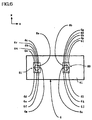
- Figs. 5A and 5B illustrate an optical head in accordance with the first embodiment of the present invention.
- An optical head in accordance with the first embodiment is comprised of a laser diode chip 1, a sub-mount 3 on which the laser diode chip 1 is mounted and which keeps the laser diode chip 1 at a predetermined height, a lens (not illustrated) for focusing a light emitted from the laser diode chip 1, onto a medium (not illustrated), an optical separator or prism 7 for separating a light reflected from the medium, from an optical axis of a light directing to the lens from the laser diode chip 1, a photodiode chip 6 receiving a light separated from the optical axis by means of the prism 7, and a quarter wavelength plate 7c mounted on the photodiode chip 6 integrally with the prism 7.
- the optical separator or prism 7 is a square pole in shape defined by a first sidewall 65a and a second sidewall 65b in parallel with each other, and first, second, third and fourth outer surfaces 66, 67, 68 and 69 all perpendicular to both the first and second sidewalls 65a and 65b.
- the first and third outer surfaces 66 and 68 are in parallel with each other.
- the prism 7 is designed to have first and second inner planes 7a and 7b both perpendicular to the first and second sidewalls 65a and 65b, in parallel with each other, and both inclined relative to the first outer surface 66 at a predetermined angle ⁇ .
- the quarter wavelength plate 7c converts a light having passed through the third outer surface 68 of the prism 7 to a circularly polarized light from a linearly polarized light, and also converts a light having been reflected from the medium from a circularly polarized light to a linearly polarized light having an orientation perpendicular to an original orientation.
- the photodiode chip 6 has a light-receiving plane 61 in parallel with the second outer surface 67. As illustrated in Fig. 6, a front light-receiving section 80 and a rear light-receiving section 81 are formed on the light-receiving plane 61.
- a light having been reflected at the first inner plane 7a forms a first beam spot 8a
- a light having been reflected at the second inner plane 7b forms a second beam spot 8b both on the photodiode chip 6.
- the front and rear light-receiving sections 80 and 81 are associated with the second and first beam spots 8b and 8a, respectively.
- the front light-receiving section 80 is comprised of six light-receiving sections 6g, 6h, 6i, 6j, 6k and 6l defined by a first front division line 6n parallel to an optically tangential direction of the medium, and second and third front division lines 6o and 6p both parallel to an optically radial direction of the medium.
- the rear light-receiving section 81 is comprised of six light-receiving sections 6a, 6b, 6c, 6d, 6e and 6f defined by a first rear division line 6m parallel to an optically tangential direction of the medium, and second and third rear division lines 6q and 6r both parallel to an optically radial direction of the medium.
- the laser diode chip 1 is positioned so that an optical length between the laser diode chip 1 and the first inner plane 7a is equal to (a + b - c)/2 wherein “a” indicates an optical length between the first inner plane 7a and the rear light-receiving section 81, “b” indicates an optical length between the second inner plane 7b and the front light-receiving section 80, and “c” indicates an optical length between the first and second inner planes 7a and 7b.
- the optical head in accordance with the first embodiment operates as follows.
- the light having left the prism 7 is converted into a circularly polarized light in the quarter wavelength plate 7c, and then, is focused onto the medium through the lens (not illustrated).
- the light having been reflected by the medium advances on the same optical path in an opposite direction, and is converted by the quarter wavelength plate 7c into a light polarized in a direction perpendicular to an original direction, that is, in an x-axis direction. Then, the light enters the prism 7 at the third outer surface 68 with an optical axis thereof being perpendicular to the third outer surface 68.
- the light having entered the prism 7 is reflected at the second inner plane 7b by half in an amount, and the remaining half passes through the second inner plane 7b.
- the light having been reflected at the second inner plane 7b leaves the prism 7 at the second outer surface 67, and is received in the front light-receiving section 80 formed on the light-receiving plane 61 of the photodiode chip 6.
- the light having passed through the second inner plane 7b is reflected at the first inner plane 7a, and leaves the prism 7 at the second outer surface 67. Then, the light is received in the rear light-receiving section 81 formed on the light-receiving plane 61 of the photodiode chip 6.
- An additional light-receiving section may be formed on the sub-mount 3. The formation of an additional light-receiving section prevents variation in an amount of a light emitted from the laser diode chip 1 which variation is caused by degradation occurring with the lapse of time, or by temperature variation.
- the quarter wavelength plate 7c may be positioned at any place intermediate between the prism 7 and the medium.
- a focus error signal FE1 is obtained by a spot-size process in accordance with the following equation, based on signals S6a to S6l detected at the light-receiving sections 6a to 6l constituting the front and rear light-receiving sections 80 and 81 formed on the light-receiving plane 61 of the photodiode chip 6.
- FE1 (S6a + S6c + S6k) - (S6b + S6j + S6l) + (S6d + S6f + S6h) - (S6e + S6g + S6i)
- a track error signal TE1 is obtained by a push-pull process in accordance with the following equation.
- TE1 (S6a + S6c + S6k) + (S6b + S6j + S6l) - (S6d + S6f + S6h) - (S6e + S6g + S6i)
- a signal indicative of data to be reproduced can be obtained as a sum of the signals S6a to S6l.
- the laser diode chip 1 and the photodiode chip 6 are fixedly installed in such a position that the first beam spot 8a is uniformly divided by the first rear division line 6m partitioning the light-receiving sections 6a, 6b and 6c from the light-receiving sections 6d, 6e and 6f, and that the second beam spot 8b is uniformly divided by the first front division line 6n partitioning the light-receiving sections 6g, 6h and 6i from the light-receiving sections 6j, 6k and 6l.
- the first and second beam spots 8a and 8b deviate in an x-axis direction, if the laser diode chip 1 and the photodiode chip 6 are assembled containing assembling error therein.
- - (S6g + S6h + S6i) + (S6j + S6k + S6l) is decreased (or increased) to a degree to which (S6a + S6b + S6c) - (S6d + S6e + S6f) is increased (or decreased).
- S6g + S6h + S6i) + (S6j + S6k + S6l) is decreased (or increased) to a degree to which (S6a + S6b + S6c) - (S6d + S6e + S6f) is increased (or decreased).
- a size of a beam spot formed on the photodiode chip 6 varies to a greater degree relative to a deviation of the medium in an optical axis direction, as an optical length between front and rear light-converging points of the photodiode chip 6 positioned so that the medium is located on a light-converging point of the lens, and the photodiode chip 6 is set shorter.
- first and second inner planes 7a and 7b are intended to narrow in order to prevent a light having been reflected at the first inner plane 7a from being reflected again at the second inner plane 7b, there is a limitation in doing so.
- a distance between the first and second inner planes 7a and 7b can be narrowed to an intended degree, for instance, by placing a base between the prism 7 and the photodiode chip 6 with a gap therebetween.
- an optical head can be designed to have a reduced thickness equal to a sum of thicknesses of the prism 7 and the photodiode chip 6.
- the first embodiment ensures no optical loss in the prism 7.
- the focus error signal FE1 is detected in the form of variation in a size of the first and second beam spots 8a and 8b in a z-axis direction, and the track error signal component is detected in the form of variation in an amount of a light of the first and second beam spots 8a and 8b in an x-axis direction, the track error signal component is unlikely to be mixed into the focus error signal FE1.
- the lens to be used in the first embodiment there may be used a single finite lens or a combination of a collimate lens and an objective lens.
- the combination may include a beam splitter located between the collimate lens and the objective lens for separating a light directing to the medium from the laser diode chip 1, or a light directing to the photodiode chip 6 from the medium. This ensures these lights to be parallel lights in the case that the medium is located on a light-converging point of the objective lens. Hence, these lights could be readily dealt with.
- the medium mentioned in the first embodiment includes an optical disc, an optical tape, and the like, and is composed of phase-change material or photo-electro-magnetic material, for instance.
- an angle formed between the first inner plane 7a and the first outer surface 66 is indicated as ⁇
- an angle formed between the first inner plane 7a and the photodiode chip 6 is indicated as ⁇
- an angle formed between the fourth outer surface 69 and the third outer surface 68 is indicated as
- a plurality of first glass plates 82 and a plurality of second glass plates 83 are alternately adhered by means of an adhesive.
- Each of the first glass plates 82 is coated with a coating A having characteristics shown in Table 1
- each of the second glass plates 83 is coated with a coating B having characteristics shown in Table 2.
- Characteristics of Coating A Direction of polarization of incident light Transmissivity Reflectivity p-polarization 100% 0 s-polarization 0 100%
- Characteristics of Coating B Direction of polarization of incident light Transmissivity Reflectivity p-polarization 100% 0 s-polarization 50%
- a resultant deposited structure 9 of the glass plates is cut into a plurality of slices 10 (see Fig. 7C) at an angle of ( ⁇ + ⁇ - 90° ) relative to a horizontal direction.
- each of the slices 10 is optically polished at cutting surfaces 10a and 10b thereof. Then, each of the slices 10 is cut at angles of ⁇ and l relative to the cutting surface 10a to thereby obtain a bar-shaped prism 11.
- a bar-shaped quarter wavelength plate 12 is adhered to the prism 11, as illustrated in Fig. 7D.
- the prism 11 with the quarter wavelength plate 12 is diced into chips.
- a bar-shaped photodiode may be adhered to the bar-shaped prism 11 prior to the dicing of the prism 11. By dicing the prism 11 to which the bar-shaped photodiode is adhered, there is obtained enhanced productivity.
- Cutting surfaces 11a and 11b of the prism 11 are optically polished before the slice 10 is diced into chips.
- cutting surfaces 11c and 11d of the prism 11 cannot be optically polished, because the bar-shaped prism 11 is too small in size to optically polish.
- the surfaces 11c and 11d remain like ground glass.
- the prism 11 is adhered to the photodiode chip 6 through the surface 11c by means of transparent adhesive, irregularity at the surface 11c is planarized with an adhesive, ensuring no scattering and aberration.
- the angle ⁇ may be set equal to 45 degrees and the angle ⁇ may be set equal to 90 degrees, in which case, even if the sub-mount 3 would have a thickness different from a designed thickness, and accordingly, a light-emitting point of the laser diode chip 1 is deviated relative to the photodiode chip 6 in a y-axis direction, a relative positional relation in a direction of an optical axis between the laser diode chip 1 and the photodiode chip 6 remains unchanged, ensuring that there is not generated focus offset caused by the deviation in the light-emitting point of the laser diode chip 1.
- An optical head in accordance with the second embodiment has almost the same structure as the structure of the optical head in accordance with the first embodiment, but is different only in that the photodiode chip 6 is replaced with a photodiode chip 14.
- Fig. 8 is a plan view of the photodiode chip 14.
- a front light-receiving section 84 and a rear light-receiving section 85 are formed on a light-receiving plane of the photodiode chip 14.
- a light having been reflected at the first inner plane 7a forms a first beam spot 8a
- a light having been reflected at the second inner plane 7b forms a second beam spot 8b both on the photodiode chip 14.
- the front and rear light-receiving sections 84 and 85 are formed in association with the second and first beam spots 8b and 8a, respectively.
- the front light-receiving section 84 is comprised of eight light-receiving sections 14i, 14j, 14k, 14l, 14m, 14n, 14o, and 14p defined by a first front division line 14r parallel to an optically tangential direction of the medium, and second, third and fourth front division lines 14s, 14t and 14u all parallel to an optically radial direction of the medium.
- the rear light-receiving section 85 is comprised of eight light-receiving sections 14a, 14b, 14d, 14d, 14e, 14f, 14g, and 14h defined by a first rear division line 14q parallel to an optically tangential direction of the medium, and second, third and fourth rear division lines 14v 14w and 14x all parallel to an optically radial direction of the medium.
- a focus error signal FE2 is obtained by a spot-size process in accordance with the following equation, based on signals S14a to S14p detected at the light-receiving sections 14a to 14p constituting the front and rear light-receiving sections 84 and 85 formed on the light-receiving plane 61 of the photodiode chip 6.
- FE2 (S14a + S14o) - (S14b + S14p) - (S14c + S14m) + (S14d + S14n) + (S14e + S14k) - (S14f + S14l) - (S14g + S14i) + (S14h + S14j)
- a track error signal TE2 is obtained by a push-pull process in accordance with the following equation.
- TE2 (S14a + S14o) + (S14b + S14p) + (S14c + S14m) + (S14d + S14n) - (S14e + S14k) - (S14f + S14l) - (S14g + S14i) - (S14h + S14j)
- a track error signal TE3 is obtained by a phase difference process as follows.
- TE3 Phase difference between (S14a + S14o) + (S14b + S14p) + (S14g + S14i) + (S14h + S14j) and (S14c + S14m) - (S14d + S14n) + (S14e + S14k) + (S14f + S14l)
- a signal indicative of data to be reproduced can be obtained as a sum of the signals S14a to S14p.
- the laser diode chip 1 and the photodiode chip 14 are fixedly installed in such a position that the first beam spot 8a is uniformly divided by the first rear division line 14q partitioning the light-receiving sections 14a, 14b, 14c and 14d from the light-receiving sections 14e, 14f, 14g and 14h, and that the second beam spot 8b is uniformly divided by the first front division line 14r partitioning the light-receiving sections 14i, 14j, 14k and 14l from the light-receiving sections 14m, 14n, 14o and 14p.
- the first and second beam spots 8a and 8b deviate in an x-axis direction, if the laser diode chip 1 and the photodiode chip 14 are assembled containing assembling error therein.
- - (S14i + S14j + S14k + S14l) + (S14m + S14n + S14o + S14p) is decreased (or increased) to a degree to which (S14a + S14b + S14c + S14d) - (S14e + S14f + S14g + S14h) is increased (or decreased).
- they are cancelled with each other, ensuring no track offset in a push-pull process.
- the laser diode chip 1 emits a light in parallel to the photodiode chip 14, an optical head can be designed to have a reduced thickness equal to a sum of thicknesses of the prism 7 and the photodiode chip 14.
- the second embodiment ensures no optical loss in the prism 7.
- the focus error signal FE2 is detected in the form of variation in a size of the first and second beam spots 8a and 8b in a z-axis direction, and the track error signal component is detected in the form of variation in an amount of a light of the first and second beam spots 8a and 8b in an x-axis direction, the track error signal component is unlikely to be mixed into the focus error signal FE2.
- An optical head in accordance with the third embodiment has almost the same structure as the structure of the optical head in accordance with the first embodiment, but is different only in that the photodiode chip 6 is replaced with a photodiode chip 15.
- Fig. 9 is a plan view of the photodiode chip 15.
- a light having been reflected at the first inner plane 7a forms a first beam spot 8a
- a light having been reflected at the second inner plane 7b forms a second beam spot 8b both on the photodiode chip 15.
- Front and rear light-receiving sections 86 and 87 are formed in association with the second and first beam spots 8b and 8a, respectively.
- the front light-receiving section 86 is comprised of first to sixth light-receiving sections 15l, 15g, 15j, 15k, 15h and 15i defined by a first front division line 15n parallel to an optically tangential direction of the medium, and second, third and fourth front division lines 15o, 15p and 15q all parallel to an optically radial direction of the medium.
- the first, fourth and third light-receiving sections 15l, 15k and 15j are located at a right side of the first front division line 15n, and the sixth, fifth and second light-receiving sections 15i, 15h and 15g are located at a left side of the first front division line 15n.
- the first, fifth and sixth light-receiving sections 15l, 15h and 15i are located at a left side of the second front division line 15o, and the third, fourth and second light-receiving sections 15j, 15k and 15g are located at a right side of the second front division line 15o.
- a light having been reflected at the second outer surface 7b and having left the prism 7 at the second outer surface 72 passes an intersection between the first front division line 15n and the second front division line 15o.
- the rear light-receiving section 87 is comprised of seventh to twelfth light-receiving sections 15d, 15c, 15e, 15f, 15a and 15b defined by a first rear division line 15m parallel to an optically tangential direction of the medium, and second, third and fourth rear division lines 15r, 15s and 15t all parallel to an optically radial direction of the medium.
- the ninth, tenth and seventh light-receiving sections 15e, 15f and 15d are located at a right side of the first rear division line 15m, and the eighth, eleventh and twelfth light-receiving sections 15c, 15a and 15b are located at a left side of the first rear division line 15m.
- the ninth, tenth and eighth light-receiving sections 15e, 15f and 15c are located at a left side of the second rear division line 15r, and the seventh, eleventh and twelfth light-receiving sections 15d, 15a and 15b are located at a right side of the second rear division line 15r.
- a light having been reflected at the first outer surface 7a and having left the prism 7 at the second outer surface 72 passes an intersection between the first rear division line 15m and the second rear division line 15r.
- a focus error signal FE3 is obtained by a spot-size process in accordance with the following equation, based on signals S15a to S15l detected at the light-receiving sections 15a to 15l constituting the front and rear light-receiving sections 86 and 87 formed on the light-receiving plane 61 of the photodiode chip 6.
- FE3 (S15a + S15f +S15h + S15k) - (S15b + S15e + S15i + S15j)
- a track error signal TE4 is obtained by a push-pull process in accordance with the following equation.
- TE4 S15c - S15d - S15g + S15l
- a track error signal TE5 is obtained by a phase difference process as follows.
- TE5 Phase difference between (S15c + S15d) and (S15g + S15l)
- a signal indicative of data to be reproduced can be obtained as a sum of the signals S15c, S15d, S15g and S15l.
- the laser diode chip 1 and the photodiode chip 15 are fixedly installed in such a position that the first beam spot 8a is uniformly divided by the first rear division line 15m partitioning the light-receiving sections 15a, 15b and 15c from the light-receiving sections 15d, 15e and 15f, and that the second beam spot 8b is uniformly divided by the first front division line 15n partitioning the light-receiving sections 15g, 15h and 15i from the light-receiving sections 15j, 15k and 15l.
- the first and second beam spots 8a and 8b deviate in an x-axis direction, if the laser diode chip 1 and the photodiode chip 15 are assembled containing assembling error therein.
- assembling error exists in the laser diode chip 1 and the photodiode chip 15
- - (S15g + S15l) is decreased (or increased) to a degree to which (S15c - S15d) is increased (or decreased).
- S15g + S15l is decreased (or increased) to a degree to which (S15c - S15d) is increased (or decreased).
- the laser diode chip 1 emits a light in parallel to the photodiode chip 15, an optical head can be designed to have a reduced thickness equal to a sum of thicknesses of the prism 7 and the photodiode chip 15.
- the third embodiment ensures no optical loss in the prism 7.
- the focus error signal FE3 is detected in the form of variation in a size of the first and second beam spots 8a and 8b in a z-axis direction, and the track error signal component is detected in the form of variation in an amount of a light of the first and second beam spots 8a and 8b in an x-axis direction, the track error signal component is unlikely to be mixed into the focus error signal FE3.
- the light-receiving sections 15a to 15l generate pairs of an electron and a hole on receipt of a light, that is, act as a current source.
- Wirings connected to the light-receiving sections can be collected into a bundle, if they are represented as an adding component in the equation for calculating the focus error signal and the track error signal.
- a current signal running through a wiring is converted into a voltage signal by means of an electron amplifier. Noises in the electron amplifier exerts a greater influence on a voltage signal converted from a smaller current. Thus, it is important to bundle as much as wirings to thereby increase a current per a wiring.
- wirings electrically connected to the eleventh, tenth, fifth and fourth light-receiving sections 15a, 15f, 15h and 15k can be bundled into a single wiring, and wiring electrically connected to the twelfth, ninth, sixth and third light-receiving sections 15b, 15e, 15i and 15j can be bundled into a single wiring.
- the third embodiment makes noises in an electron amplifier smaller than the above-mentioned second embodiment.
- Figs. 10A and 10B illustrate an optical head in accordance with the fourth embodiment of the present invention.
- An optical head in accordance with the fourth embodiment is comprised of a laser diode chip 1, a sub-mount 4 on which the laser diode chip 1 is mounted and which keeps the laser diode chip 1 at a predetermined height, a lens (not illustrated) for focusing a light emitted from the laser diode chip 1, onto a medium (not illustrated), an optical separator or prism 17 for separating a light reflected from the medium, from an optical axis of a light directing to the lens from the laser diode chip 1, a photodiode chip 16 receiving a light separated from the optical axis by means of the prism 17, a base 17d sandwiched between the prism 17 and the photodiode chip 16 and composed of light-permeable material, and a quarter wavelength plate 17e mounted on the photodiode chip 16 integrally with the prism 17 and the base 17d.
- the optical separator or prism 17 is a rectangular parallelopiped in shape defined by a first sidewall 70a and a second sidewall 70b in parallel with each other, and first, second, third and fourth outer surfaces 71, 72, 73 and 74 all perpendicular to both the first and second sidewalls 70a and 70b.
- the first and third outer surfaces 71 and 73 are in parallel with each other.
- the prism 17 is designed to have first, second and third inner planes 17a, 17b and 17c all perpendicular to the first and second sidewalls 70a and 70b, in parallel with one another, and all inclined relative to the first outer surface 71 at a predetermined angle of 45 degrees.
- the quarter wavelength plate 17e converts a light having passed through the third outer surface 73 of the prism 17 to a circularly polarized light from a linearly polarized light, and also converts a light having been reflected from the medium from a circularly polarized light to a linearly polarized light having an orientation perpendicular to an original orientation.
- the photodiode chip 16 has a light-receiving plane 161 in parallel with the second outer surface 72. As illustrated in Fig. 11, a front light-receiving section 88, a rear light-receiving section 89 and an additional light-receiving section 90 are formed on the light-receiving plane 161.
- a light having been reflected at the first inner plane 17a forms a first beam spot 18a
- a light having been reflected at the second inner plane 17b forms a second beam spot 18b
- a light having been reflected at the third inner plane 17c forms a third beam spot 18c all on the photodiode chip 16.
- the front, rear and additional light-receiving sections 88, 89 and 90 are associated with the second, first and third beam spots 18b, 18a and 18c, respectively.
- the front light-receiving section 88 is comprised of three light-receiving sections 16d, 16e and 16f defined by two division lines parallel to an optically radial direction of the medium.
- the rear light-receiving section 89 is comprised of three light-receiving sections 16a, 16b and 16c defined by two division lines parallel to an optically radial direction of the medium.
- the additional light-receiving section 90 is comprised of two light-receiving sections 16g and 16h defined by a division line parallel to an optically tangential direction of the medium.
- the laser diode chip 1 is positioned so that an optical length between the laser diode chip 1 and the first inner plane 17a is equal to (a + b - c)/2 wherein "a” indicates an optical length between the first inner plane 17a and the rear light-receiving section 89, “b” indicates an optical length between the second inner plane 17b and the front light-receiving section 88, and "c" indicates an optical length between the first and second inner planes 17a and 17b.
- the optical head in accordance with the fourth embodiment operates as follows.
- the light having left the prism 17 is converted into a circularly polarized light in the quarter wavelength plate 17e, and then, is focused onto the medium through the lens (not illustrated).
- the light having been reflected by the medium advances on the same optical path in an opposite direction, and is converted by the quarter wavelength plate 17e into a light polarized in an x-axis direction. Then, the light enters the prism 17 at the third outer surface 73 with an optical axis thereof being perpendicular to the third outer surface 73.
- the light having entered the prism 17 is reflected at the third inner plane 17c by ⁇ % (0 ⁇ ⁇ ⁇ 100), and the remaining portion of the light passes through the third inner plane 17c, that is, the light passes through the third inner plane 17c by (100- ⁇ )%.
- the light having been reflected at the third inner plane 17c leaves the prism 17 at the second outer surface 72, passes through the base 17d, enters the photodiode chip 16, and is received in the additional light-receiving section 90 formed on the light-receiving plane 161 of the photodiode chip 16.
- the light having passed through the third inner plane 17c is reflected at the second inner plane 17b by half in an amount, and the remaining half passes through the second inner plane 17b.
- the light having been reflected at the second inner plane 17b leaves the prism 17 at the second outer surface 72, passes through the base 17d, enters the photodiode chip 16, and is received in the front light-receiving section 88 formed on the light-receiving plane 161 of the photodiode chip 16.
- the light having passed through the second inner plane 17b is reflected at the first inner plane 17a, passes through the base 17d, enters the photodiode chip 16, and is received in the rear light-receiving section 89 formed on the light-receiving plane 161 of the photodiode chip 16.
- An additional light-receiving section may be formed on the sub-mount 4, similarly to the above-mentioned first embodiment.
- the formation of such an additional light-receiving section prevents variation in an amount of a light emitted from the laser diode chip 1 which variation is caused by degradation occurring with the lapse of time, or by temperature variation.
- the photodiode chip 16 may be designed to have an alignment mark or marks for accurately mounting the sub-mount 4 on the photodiode chip 16.
- the quarter wavelength plate 17e may be positioned at any place intermediate between the prism 17 and the medium.
- a focus error signal FE4 is obtained by a spot-size process in accordance with the following equation, based on signals S16a to S16h detected at the light-receiving sections 16a to 16h constituting the front, rear and additional light-receiving sections 88, 89 and 90 formed on the light-receiving plane 161 of the photodiode chip 16.
- FE4 S16a - S16b + S16c - S16d + S16e - S16f
- a track error signal TE6 is obtained by a push-pull process in accordance with the following equation.
- TE6 S16g - S16h
- a signal indicative of data to be reproduced can be obtained as a sum of the signals S16g and S16h.
- the first and second beam spots 8a and 8b are deviated in an x-axis direction due to assembling error in the laser diode chip 1 and the photodiode chip 6 or 16, they are uniformly deviated. That is, if a light emitted from the laser diode chip 1 does not have an optical axis in parallel with a z-axis, there would be generated track offset in a push-pull process. In addition, even if a light emitted from the laser diode chip 1 has an optical axis in parallel with a z-axis, a track error signal obtained by a push-pull process would have a reduced signal amplitude.
- the beam spot 18c is greater in size than the beams spots 8a and 8b, which ensures the laser diode chip 1 to have greater tolerance in an x-axis direction.
- the laser diode chip 1 is given greater tolerance for rotation in an x-z plane.
- Each of the first and second inner planes 17a and 17b makes an angle of 45 degrees relative to the first outer surface 71 of the prism 17, and the photodiode chip 16 makes an angle of 90 degrees relative to the first outer surface 71.
- the sub-mount 4 would have a thickness different from a designed thickness, and accordingly, a light-emitting point of the laser diode chip 1 is deviated relative to the photodiode chip 16 in a y-axis direction, a relative positional relation in a direction of an optical axis between the laser diode chip 1 and the photodiode chip 16 remains unchanged, ensuring that there is not generated focus offset caused by the deviation in the light-emitting point of the laser diode chip 1.
- a size of a beam spot formed on the photodiode chip 16 varies to a greater degree relative to a deviation of the medium in an optical axis direction, as an optical length between front and rear light-converging points of the photodiode chip 16 positioned so that the medium is located on a light-converging point of the lens, and the photodiode chip 16 is set shorter.
- the optical head in accordance with the fourth embodiment is provided with the base 17d sandwiched between the prism 17 and the photodiode chip 16, a distance between the first and second inner planes 17a and 17b can be narrowed to an intended degree.
- an optical head can be designed to have a reduced thickness equal to a sum of thicknesses of the prism 17 and the photodiode chip 16.
- the fourth embodiment ensures no optical loss in the prism 17.
- the focus error signal FE4 is detected in the form of variation in a size of the first and second beam spots 18a and 18b in a z-axis direction, and the track error signal component is detected in the form of variation in an amount of a light of the first and second beam spots 18a and 18b in an x-axis direction, the track error signal component is unlikely to be mixed into the focus error signal FE4.
- the lens to be used in the fourth embodiment there may be used a single finite lens or a combination of a collimate lens and an objective lens.
- the combination may include a beam splitter located between the collimate lens and the objective lens for separating a light directing to the medium from the laser diode chip 1, or a light directing to the photodiode chip 16 from the medium. This ensures these lights to be parallel lights in the case that the medium is located on a light-converging point of the objective lens. Hence, these lights could be readily dealt with.
- the medium mentioned in the fourth embodiment includes an optical disc, an optical tape, and the like, and may be composed of phase-change material or photo-electro-magnetic material, for instance.
- the above-mentioned constant ⁇ can be selected among figures in the range of 0 to 100 both inclusive in dependence on specific material of which the medium is composed.
- the constant ⁇ may be set equal to 50 or 80.
- An optical head in accordance with the fifth embodiment has almost the same structure as the structure of the optical head in accordance with the fourth embodiment, but is different only in that the photodiode chip 16 is replaced with a photodiode chip 19.
- Fig. 12 is a plan view of the photodiode chip 19.
- a front light-receiving section 91, a rear light-receiving section 92, and an additional light-receiving section 93 are formed on a light-receiving plane 191 of the photodiode chip 19.
- a light having been reflected at the first inner plane 17a forms a first beam spot 18a
- a light having been reflected at the second inner plane 17b forms a second beam spot 18b
- a light having been reflected at the third inner plane 17c forms a third beam spot 18c all on the photodiode chip 19.
- the front, rear and additional light-receiving sections 91, 92 and 93 are formed in association with the second, first and third beam spots 18b, 18a and 18c, respectively.
- the front light-receiving section 91 is comprised of three light-receiving sections 19d, 19e and 19f defined by two division lines parallel to an optically radial direction of the medium.
- the rear light-receiving section 92 is comprised of three light-receiving sections 19a, 19b and 19c defined by two division lines parallel to an optically radial direction of the medium.
- the additional light-receiving section 93 is comprised of four light-receiving sections 19g, 19h, 19i and 19j defined by both a division line parallel to an optically tangential direction of the medium and a division line parallel to an optically radial direction of the medium.
- a focus error signal FE5 is obtained by a spot-size process in accordance with the following equation, based on signals S19a to S19j detected at the light-receiving sections 19a to 19j constituting the front, rear and additional light-receiving sections 91, 92 and 93 formed on the light-receiving plane 191 of the photodiode chip 19.
- FE5 S19a - S19b + S19c - S19d + S19e - S19f
- Track error signals TE7 and TE8 are obtained by a push-pull process and a phase difference process, respectively, in accordance with the following equations.
- TE7 S19g + S19h - S19i - S19j
- TE8 Phase difference between (S19g + S19j) and (S19h + S19i)
- a signal indicative of data to be reproduced can be obtained as a sum of the signals S19g, S19h, S19i and S19j.
- the first and second beam spots 8a and 8b are deviated in an x-axis direction due to assembling error in the laser diode chip 1 and the photodiode chip 19, they are uniformly deviated. That is, if a light emitted from the laser diode chip 1 does not have an optical axis in parallel with a z-axis, there would be generated track offset in a push-pull process. In addition, even if a light emitted from the laser diode chip 1 has an optical axis in parallel with a z-axis, a track error signal obtained by a push-pull process would have a reduced signal amplitude.
- the beam spot 18c is greater in size than the beams spots 8a and 8b, which ensures the laser diode chip 1 to have greater tolerance in an x-axis direction.
- the laser diode chip 1 is given greater tolerance for rotation in an x-z plane.
- an optical head can be designed to have a reduced thickness equal to a sum of thicknesses of the prism 17 and the photodiode chip 19.
- the fifth embodiment ensures no optical loss in the prism 17.
- the focus error signal FE5 is detected in the form of variation in a size of the first and second beam spots 18a and 18b in a z-axis direction, and the track error signal component is detected in the form of variation in an amount of a light of the first and second beam spots 18a and 18b in an x-axis direction, the track error signal component is unlikely to be mixed into the focus error signal FE5.
- An optical head in accordance with the sixth embodiment has almost the same structure as the structure of the optical head in accordance with the fourth embodiment, but is different only in that the photodiode chip 16 is replaced with a photodiode chip 20.
- Fig. 13 is a plan view of the photodiode chip 20.
- a front light-receiving section 94, a rear light-receiving section 95, and an additional light-receiving section 96 are formed on a light-receiving plane 201 of the photodiode chip 20.
- a light having been reflected at the first inner plane 17a forms a first beam spot 18a
- a light having been reflected at the second inner plane 17b forms a second beam spot 18b
- a light having been reflected at the third inner plane 17c forms a third beam spot 18c all on the photodiode chip 20.
- the front, rear and additional light-receiving sections 94, 95 and 96 are formed in association with the second, first and third beam spots 18b, 18a and 18c, respectively.
- the front light-receiving section 94 is comprised of seventh to twelfth light-receiving sections 20g, 20h, 20i, 20j, 20k and 20l defined by a first division line 20r parallel to an optically tangential direction of the medium, and second, third and fourth division lines 20s, 20t and 20u all parallel to an optically radial direction of the medium.
- the seventh, eighth and ninth light-receiving sections 20g, 20h and 20i are located at a left side of the first division line 20r, and the tenth, eleventh and twelfth light-receiving sections 20j, 20k and 20l are located at a right side of the first division line 20r.
- the seventh, tenth and eleventh light-receiving sections 20g, 20j and 20k are located at a right side of the second division line 20s, and the eighth, ninth and twelfth light-receiving sections 20h, 20i and 20l are located at a left side of the second division line 20s.
- the rear light-receiving section 95 is comprised of first to sixth light-receiving sections 20a, 20b, 20c, 20d, 20e and 20f defined by a fifth division line 20q parallel to an optically tangential direction of the medium, and sixth, seventh and eighth division lines 20v, 20w and 20x all parallel to an optically radial direction of the medium.
- the first, second and third light-receiving sections 20a, 20b and 20c are located at a left side of the fifth division line 20q, and the fourth, fifth and sixth light-receiving sections 20d, 20e and 20f are located at a right side of the fifth division line 20q.
- the first, second and fourth light-receiving sections 20a, 20b and 20d are located at a right side of the sixth division line 20v, and the third, fifth and sixth light-receiving sections 20c, 20e and 20f are located at a left side of the sixth division line 20v.
- the additional light-receiving section 96 is comprised of four light-receiving sections 20m, 20n, 20o and 20p defined by both a ninth division line 20y parallel to an optically tangential direction of the medium and a tenth division line 20z parallel to an optically radial direction of the medium.
- a focus error signal FE6 is obtained by a spot-size process in accordance with the following equation, based on signals S20a to S20p detected at the light-receiving sections 20a to 20p constituting the front, rear and additional light-receiving sections 94, 95 and 96 formed on a light-receiving plane of the photodiode chip 20.
- FE6 S20a - S20b - S20e + S20f + S20h - S20i - S20j + S20k
- Track error signals TE9 and TE10 are obtained by a push-pull process and a phase difference process, respectively, in accordance with the following equations.
- TE9 S20c - S20d - S20g + S20l
- TE10 Phase difference between (S20m + S20p) and (S20n + S20o)
- a signal indicative of data to be reproduced can be obtained as a sum of the signals S20m, S20n, S20o and S20p.
- the laser diode chip 1 and the photodiode chip 20 are fixedly installed in such a position that the first beam spot 18a is uniformly divided by the fifth division line 20q partitioning the light-receiving sections 20a, 20b and 20c from the light-receiving sections 20d, 20e and 20f, and that the second beam spot 18b is uniformly divided by the first division line 20r partitioning the light-receiving sections 20g, 20h and 20i from the light-receiving sections 20j, 20k and 20l.
- the first and second beam spots 18a and 18b deviate in an x-axis direction, if the laser diode chip 1 and the photodiode chip 20 are assembled containing assembling error therein.
- - (S20g + S20l) is decreased (or increased) to a degree to which (S20c - S20d) is increased (or decreased).
- S20c - S20d is increased (or decreased).
- the track error signal TE10 is less influenced by deviation of the laser diode chip 1 in an x-axis direction than the track error signal TE9.
- an optical head can be designed to have a reduced thickness equal to a sum of thicknesses of the prism 17 and the photodiode chip 20.
- the sixth embodiment ensures no optical loss in the prism 17.
- the focus error signal FE6 is detected in the form of variation in a size of the first and second beam spots 18a and 18b in a z-axis direction, and the track error signal component is detected in the form of variation in an amount of a light of the first and second beam spots 18a and 18b in an x-axis direction, the track error signal component is unlikely to be mixed into the focus error signal FE6.
- An optical head in accordance with the seventh embodiment has almost the same structure as the structure of the optical head in accordance with the fourth embodiment, but is different only in that the photodiode chip 16 is replaced with a photodiode chip 21.
- Fig. 14 is a plan view of the photodiode chip 21.
- the photodiode chip 21 is different from the photodiode chip illustrated in Fig. 13 in a structure of an additional light-receiving section.
- the photodiode chip 21 is designed to have an additional light-receiving section 99 in place of the additional light-receiving section 96.
- the additional light-receiving section 99 is comprised of two light-receiving sections 21m and 21n partitioned by a division line 21o parallel to an optically tangential direction of the medium.
- a focus error signal FE7 is obtained by a spot-size process in accordance with the following equation, based on signals S21a to S21n detected at the light-receiving sections 21a to 21n constituting the front, rear and additional light-receiving sections 97, 98 and 99 formed on a light-receiving plane of the photodiode chip 21.
- FE7 S21a - S21b - S21e + S21f + S21h - S21i - S21j + S21k
- Track error signals TE11 and TE12 are obtained by a push-pull process and a phase difference process, respectively, in accordance with the following equations.
- TE11 S21m - S21n
- TE12 Phase difference between (S21c + S21d) and (S21g + S21l)
- a signal indicative of data to be reproduced can be obtained as a sum of the signals S21m and S21n.
- the first and second beam spots 8a and 8b are deviated in an x-axis direction due to assembling error in the laser diode chip 1 and the photodiode chip 21, they are uniformly deviated. That is, if a light emitted from the laser diode chip 1 does not have an optical axis in parallel with a z-axis, there would be generated track offset in a push-pull process. In addition, even if a light emitted from the laser diode chip 1 has an optical axis in parallel with a z-axis, a track error signal obtained by a push-pull process would have a reduced signal amplitude.
- the beam spot 18c is greater in size than the beams spots 8a and 8b, which ensures the laser diode chip 1 to have greater tolerance in an x-axis direction.
- an optical head can be designed to have a reduced thickness equal to a sum of thicknesses of the prism 17 and the photodiode chip 21.
- the seventh embodiment ensures no optical loss in the prism 17.
- the focus error signal FE7 is detected in the form of variation in a size of the first and second beam spots 18a and 18b in a z-axis direction, and the track error signal component is detected in the form of variation in an amount of a light of the first and second beam spots 18a and 18b in an x-axis direction, the track error signal component is unlikely to be mixed into the focus error signal FE7.
- Figs. 15A and 15B illustrate an optical head in accordance with the eighth embodiment of the present invention.
- An optical head in accordance with the eighth embodiment is comprised of a laser diode chip 1, a sub-mount 4 on which the laser diode chip 1 is mounted and which keeps the laser diode chip 1 at a predetermined height, a lens (not illustrated) for focusing a light emitted from the laser diode chip 1, onto a medium (not illustrated), an optical separator or prism 23 for separating a light reflected from the medium, from an optical axis of a light directing to the lens from the laser diode chip 1, a photodiode chip 22 receiving a light separated from the optical axis by means of the prism 23, a base 23c sandwiched between the prism 23 and the photodiode chip 22 and composed of light-permeable material, a two-divisional grating 24 located in facing relation with the prism 23 and acting as a diffraction device, and a quarter wavelength plate 25 located in alignment with the two-divisional grating 24.
- the optical separator or prism 23 is a rectangular parallelopiped in shape defined by a first sidewall 75a and a second sidewall 75b in parallel with each other, and first, second, third and fourth outer surfaces 76, 77, 78 and 79 all perpendicular to both the first and second sidewalls 75a and 75b.
- the first and third outer surfaces 76 and 78 are in parallel with each other.
- the prism 23 is designed to have first and second inner planes 23a and 23b both perpendicular to the first and second sidewalls 75a and 75b, in parallel with one another, and both inclined relative to the first outer surface 76 at a predetermined angle of 45 degrees.
- the two-divisional grating 24 is designed to have first and second regions 24a and 24b partitioned by a division line parallel to a y-axis.
- the quarter wavelength plate 25 converts a light having passed through the third outer surface 78 of the prism 23 to a circularly polarized light from a linearly polarized light, and also converts a light having been reflected from the medium from a circularly polarized light to a linearly polarized light having an orientation perpendicular to an original orientation.
- the photodiode chip 22 has a light-receiving plane 221 in parallel with the second outer surface 77. As illustrated in Fig. 17, a front light-receiving section 300 and a rear light-receiving section 301 are formed on the light-receiving plane 221.
- a light having been reflected at the first inner plane 23a forms five beam spots 26a, 26c, 26d, 26g and 26h
- a light having been reflected at the second inner plane 23b forms five beam spots 26b, 26e, 26f, 26i and 26j.
- the beam spots 26c, 26e, 26h and 26j are comprised of a diffracted light passing through the first region 24a of the two-divisional grating 24, and the beam spots 26d, 26f, 26g and 26i are comprised of a diffracted light passing through the second region 24b of the two-divisional grating 24.
- the beam spots 26a and 26b are comprised of a transmitted light passing through the two-divisional grating 24.
- the beam spots 26c, 26d, 26g and 26h are all semicircular in shape, and are positioned radially around the beam spot 26a which is circular in shape.
- the beam spots 26e, 26f, 26i and 26j are all semicircular in shape, and are positioned radially around the beam spot 26b which is circular in shape.
- the beam spots 26c and 26g are positioned so that the arcuate portions of them face inwardly
- the beam spots 26d and 26h are positioned so that the arcuate portions of them face outwardly.
- the beam spots 26e and 26i are positioned so that the arcuate portions of them face outwardly
- the beam spots 26f and 26j are positioned so that the arcuate portions of them face inwardly.
- the front light-receiving section 300 is associated with the beam spots 26b, 26e, 26f, 26i and 26j
- the rear light-receiving section 301 is associated with the beam spots 26a, 26c, 26d, 26g and 26h.
- the front light-receiving section 300 is comprised of five rectangular light-receiving sections each located around each of the beam spots 26b, 26e, 26i and 26j.
- the circular beam spot 26b are formed three light-receiving sections 22ba, 22bb and 22bc partitioned by two division lines both parallel to an optically radial direction of the medium.
- the semicircular beam spots 26e, 26f, 26i and 26j are formed rectangular light-receiving sections 22e, 22f 22i and 22j, respectively.
- the rear light-receiving section 301 is comprised of five rectangular light-receiving sections each located around each of the beam spots 26a, 26c, 26d and 26g.
- the circular beam spot 26a are formed three light-receiving sections 22aa, 22ab and 22ac partitioned by two division lines both parallel to an optically radial direction of the medium.
- the semicircular beam spots 26c, 26d, 26g and 26h are formed rectangular light-receiving sections 22c, 22d, 22g and 22h, respectively.
- the laser diode chip 1 is positioned so that an optical length between the laser diode chip 1 and the first inner plane 23a is equal to (a + b - c)/2 wherein “a” indicates an optical length between the first inner plane 23a and the rear light-receiving section 301, “b” indicates an optical length between the second inner plane 23b and the front light-receiving section 300, and “c” indicates an optical length between the first and second inner planes 23a and 23b.
- the optical head in accordance with the eighth embodiment operates as follows.
- the light having been reflected by the medium advances on the same optical path in an opposite direction, and is converted by the quarter wavelength plate 25 into a light polarized in an x-axis direction. Then, the light is separated into a diffracted light and a transmitted light in the two-divisional grating 24. Then, the transmitted light enters the prism 23 at the third outer surface 78 with an optical axis thereof being perpendicular to the third outer surface 78.
- Fig. 15A illustrates only the transmitted light passing through the two-divisional grating 24, and does not illustrate the diffracted light.
- the light having been reflected at the second inner plane 23b leaves the prism 23 at the second outer surface 77, passes through the base 23c, enters the photodiode chip 22, and is received in the front light-receiving section 300 formed on the light-receiving plane 221 of the photodiode chip 22.
- the light having passed through the second inner plane 23b is reflected at the first inner plane 23a, leaves the prism 23 at the second outer surface 77, passes through the base 23c, enters the photodiode chip 22, and is received in the rear light-receiving section 301 formed on the light-receiving plane 221 of the photodiode chip 22.
- An additional light-receiving section may be formed on the sub-mount 4, similarly to the above-mentioned first embodiment.
- the formation of such an additional light-receiving section prevents variation in an amount of a light emitted from the laser diode chip 1 which variation is caused by degradation occurring with the lapse of time, or by temperature variation.
- the photodiode chip 22 may be designed to have an alignment mark or marks for accurately mounting the sub-mount 4 on the photodiode chip 22.
- the quarter wavelength plate 25 may be positioned at any place intermediate between the two-divisional grating 24 and the medium.
- a focus error signal FE8 is obtained by a spot-size process in accordance with the following equation, based on signals S22aa to S22j detected at the light-receiving sections 22aa to 22j constituting the front and rear light-receiving sections 300 and 301 formed on the light-receiving plane 221 of the photodiode chip 22.
- FE8 S22aa - S22ab + S22ac - S22ba + S22bb - S22bc
- a track error signal TE13 is obtained by a push-pull process in accordance with the following equation.
- TE13 (S22c + S22e + S22h + S22j) - (S22d + S22f + S22g + S22i)
- a signal indicative of data to be reproduced can be obtained as a sum of the signals S22c, S22e, S22h, S22j, S22d, S22f, S22g and S22i.
- the photodiode chip 22 is not formed with a division line parallel to a z-axis, there would not be generated track offset, and the focus error signal would not be influenced.
- the two-divisional grating 24 is deviated in an x-axis direction, there would be generated track offset. However, a light having been reflected at the medium could have great tolerance in an x-axis direction, because the light has a great diameter in the two-divisional grating 24. In addition, since the two-divisional grating 24 does not have a division line parallel to an x-axis, and is uniform in a y-axis direction, a tolerance in a y-axis direction is infinite, unless the light is not out of the two-divisional grating 24.
- a diffraction angle of the diffracted light emitted from the two-divisional grating 24 would also vary.
- none of the beam spots 26c to 26j is cross over a plurality of the light-receiving sections, and hence, is influenced by the variation in a diffraction angle of the diffracted light.
- the two-divisional grating 24 may be replaced with a hologram device having a lens function.
- a hologram device would provide convergence and divergence functions to the diffracted light.
- Each of the first and second inner planes 23a and 23b makes an angle of 45 degrees relative to the first outer surface 76 of the prism 23, and the photodiode chip 22 makes an angle of 90 degrees relative to the first outer surface 76.
- the sub-mount 4 would have a thickness different from a designed thickness, and accordingly, a light-emitting point of the laser diode chip 1 is deviated relative to the photodiode chip 22 in a y-axis direction, a relative positional relation in a direction of an optical axis between the laser diode chip 1 and the photodiode chip 22 remains unchanged, ensuring that there is not generated focus offset caused by the deviation in the light-emitting point of the laser diode chip 1.
- a size of a beam spot formed on the photodiode chip 22 varies to a greater degree relative to a deviation of the medium in an optical axis direction, as an optical length between front and rear light-converging points of the photodiode chip 22 positioned so that the medium is located on a light-converging point of the lens, and the photodiode chip 22 is set shorter.
- the optical head in accordance with the eighth embodiment is provided with the base 23c sandwiched between the prism 23 and the photodiode chip 22, a distance between the first and second inner planes 23a and 23b can be narrowed to an intended degree.
- an optical head can be designed to have a reduced thickness equal to a sum of thicknesses of the prism 23 and the photodiode chip 22.
- the eighth embodiment ensures no optical loss in the prism 23.
- the focus error signal FE8 is detected in the form of variation in a size of the first and second beam spots 26a and 26b in a z-axis direction, and the track error signal component is detected in the form of variation in an amount of a light of the first and second beam spots 26a and 26b in an x-axis direction, the track error signal component is unlikely to be mixed into the focus error signal FE8.
- the lens to be used in the eighth embodiment there may be used a single finite lens or a combination of a collimate lens and an objective lens.
- the combination may include a beam splitter located between the collimate lens and the objective lens for separating a light directing to the medium from the laser diode chip 1, or a light directing to the photodiode chip 22 from the medium. This ensures these lights to be parallel lights in the case that the medium is located on a light-converging point of the objective lens. Hence, these lights could be readily dealt with.
- the medium mentioned in the eighth embodiment includes an optical disc, an optical tape, and the like, and may be composed of phase-change material or photo-electro-magnetic material, for instance.
- the two-divisional grating 24 may be comprised of a device composed of lithium niobate crystal on which a grid-like slit is formed in dependence on whether proton is exchanged or not. Namely, the two-divisional grating 24 utilizes the fact that an index ellipsoid is deformed, if proton exchange is applied to lithium niobate crystal.
- a phase difference between dielectric films deposited on a region to which proton exchange is applied, and a portion to which proton exchange is not applied is multiplied by N ⁇ for a light polarized in a y-axis direction, and is set equal to an appropriate value for a light polarized in an x-axis direction, wherein N is an even integer and ⁇ is indicated in a unit of radian.
- the two-divisional grating 24 can be designed to allow a light polarized in a y-axis direction to pass therethrough, and a light polarized in an x-axis direction to diffract and pass therethrough.
- An optical head in accordance with the ninth embodiment has almost the same structure as the structure of the optical head in accordance with the eighth embodiment, but is different only in that the photodiode chip 22 is replaced with a photodiode chip 27.
- Fig. 18 is a plan view of the photodiode chip 27.
- the photodiode chip 27 has almost the same structure as the structure of the photodiode chip 22, but is different only in a shape of the light-receiving sections formed in association with the semicircular beam spots. Specifically, each of the rectangular light-receiving sections formed in association with the semicircular beam spots 26c, 26d, 26e, 26f, 26g, 26h, 26i and 26j is partitioned into two regions by a division line parallel to an optically radial direction of the medium.
- the rectangular light-receiving sections formed around the semicircular beam spots 26c, 26d, 26e, 26f, 26g, 26h, 26i and 26j include regions 27ca and 27cb, 27da and 27db, 27ea and 27eb, 27fa and 27fb, 27ga and 27gb, 27ha and 27hb, 27ia and 27ib, and 27ja and 27jb, respectively.
- a focus error signal FE9 is obtained by a spot-size process in accordance with the following equation, based on signals S27aa to S27jb detected at the light-receiving sections 27aa to 27jb constituting the front and rear light-receiving sections 302 and 303 formed on a light-receiving plane of the photodiode chip 27.
- FE9 S27aa - S27ab + S27ac - S27ba + S27bb - S27bc
- Track error signals TE14 and TE15 are obtained by a push-pull process and a phase difference process, respectively, in accordance with the following equations.
- TE14 (S27ca + S27eb + S27ha + S27jb) + (S27cb + S27ea + S27hb + S27ja) - (S27da + S27fb + S27ga + S27ib) - (S27db + S27fa + S27gb + S27ia)
- TE15 Phase difference between (S27ca + S27eb + S27ha + S27jb) + (S27db + S27fa + S27gb + S27ia) and (S27cb + S27ea + S27hb + S27ja) + (S27da + S27fb + S27ga + S27ib)
- a signal indicative of data to be reproduced can be obtained as a sum: (S27ca + S27eb + S27ha + S27jb) + (S27cb + S27ea + S27hb + S27ja) + (S27da + S27fb + S27ga + S27ib) + (S27db + S27fa + S27gb + S27ia)
- the photodiode chip 27 is not formed with a division line parallel to a z-axis, there would not be generated track offset, and the focus error signal would not be influenced.
- an optical head can be designed to have a reduced thickness equal to a sum of thicknesses of the prism 23 and the photodiode chip 27.
- the ninth embodiment ensures no optical loss in the prism 23.
- the focus error signal FE9 is detected in the form of variation in a size of the first and second beam spots 26a and 26b in a z-axis direction, and the track error signal component is detected in the form of variation in an amount of a light of the first and second beam spots 26a and 26b in an x-axis direction, the track error signal component is unlikely to be mixed into the focus error signal FE9.
- An optical head in accordance with the tenth embodiment has almost the same structure as the structure of the optical head in accordance with the eighth embodiment, but is different only in that the two-divisional grating 24 is replaced with a four-divisional grating 29, and that the photodiode chip 22 is replaced with a photodiode chip 28.
- Fig. 19 is a right side view of the four-divisional grating 29, and
- Fig. 20 is a plan view of the photodiode chip 28.
- the four-divisional grating 29 is divided into first to fourth regions 29a, 29b, 29c and 29d by two division lines extending in y-and x-axes directions.
- the photodiode chip 28 has a light-receiving plane 281 in parallel with the second outer surface 77. As illustrated in Fig. 20, a front light-receiving section 304 and a rear light-receiving section 305 are formed on the light-receiving plane 281.
- a light having been reflected at the first inner plane 23a forms nine beam spots 30a, 30ca, 30cb, 30dc, 30dd, 30gc, 30gd, 30ha and 30hb on the photodiode chip 28, and a light having been reflected at the second inner plane 23b forms nine beam spots 30b, 30ea, 30eb, 30fc, 30fd, 30ic, 30id, 30ja and 30jb on the photodiode chip 28.
- the beam spots 30ca, 30ea, 30ha and 30ja are comprised of diffracted lights passing through the first region 29a of the four-divisional grating 29.
- the beam spots 30cb, 30eb, 30hb and 30jb are comprised of diffracted lights passing through the second region 29b of the four-divisional grating 29.
- the beam spots 30dc, 30fc, 30gc and 30ic are comprised of diffracted lights passing through the third region 29c of the four-divisional grating 29.
- the beam spots 30dd, 30fd, 30gd and 30id are comprised of diffracted lights passing through the fourth region 29d of the four-divisional grating 29.
- the beam spots 30a and 30b are comprised of transmitted lights emitted from the four-divisional grating 29.
- the eight beam spots 30ea, 30eb, 30fc, 30fd, 30ic, 30id, 30ja and 30jb in the front light-receiving section 304, except the beam spot 30b, are quadrants in shape, and are arranged around the beam spot 30b which is circular in shape.
- the eight beam spots 30ca, 30cb, 30dc, 30dd, 30gc, 30gd, 30ha and 30hb in the rear light-receiving section 305, except the beam spot 30a are quadrants in shape, and are arranged around the beam spot 30a which is circular in shape.
- Each of the beam spots is formed by diving each of the semicircular beam spots in the eighth embodiment into quadrants.
- the quadrant beam spots are spaced away from one another in a direction parallel to an optically radial direction of the medium.
- the front light-receiving section 304 is formed in association with the beam spots 30b, 30ea, 30eb, 30fc, 30fd, 30ic, 30id, 30ja and 30jb
- the rear light-receiving section 305 is formed in association with the beam spots 30a, 30ca, 30cb, 30dc, 30dd, 30gc, 30gd, 30ha and 30hb.
- the front light-receiving section 304 is comprised of rectangular light-receiving sections formed around the beam spots 30b, 30ea, 30eb, 30fc, 30fd, 30ic, 30id, 30ja and 30jb.
- the circular beam spot 30b are formed three light-receiving sections 28ba, 28bb and 28bc partitioned by two division lines both parallel to an optically radial direction of the medium.
- Rectangular light-receiving sections 28ea, 28eb, 28fc, 28fd, 28ic, 28id, 28ja and 28jb are formed around the quadrant beam spots 30ea, 30eb, 30fc, 30fd, 30ic, 30id, 30ja and 30jb, respectively.
- the rear light-receiving section 305 is comprised of rectangular light-receiving sections formed around the beam spots 30a, 30ca, 30cb, 30dc, 30dd, 30gc, 30gd, 30ha and 30hb.
- the circular beam spot 30a are formed three light-receiving sections 28aa, 28ab and 28ac partitioned by two division lines both parallel to an optically radial direction of the medium.
- Rectangular light-receiving sections 28ca, 28cb, 28dc, 28dd, 28gc, 28gd, 28ha and 28hb are formed around the quadrant beam spots 30ca, 30cb, 30dc, 30dd, 30gc, 30gd, 30ha and 30hb, respectively.
- a focus error signal FE10 is obtained by a spot-size process in accordance with the following equation, based on signals S28aa to S28jb detected at the light-receiving sections 28aa to 28jb constituting the front and rear light-receiving sections 304 and 305 formed on a light-receiving plane of the photodiode chip 28.
- FE10 S28aa - S28ab + S28ac - S28ba + S28bb - S28bc
- Track error signals TE16 and TE17 are obtained by a push-pull process and a phase difference process, respectively, in accordance with the following equations.
- TE16 (S28ca + S28ea + S28ha + S28ja) + (S28cb + S28eb + S28hb + S28jb) - (S28dc + S28fc + S28gc + S28ic) - (S28dd + S28fd + S28gd + S28id)
- TE17 Phase difference between (S28ca + S28ea + S28ha + S28ja) + (S28ddd + S28fd + S28gd + S28id) and (S28cb + S28eb + S28hb + S28jb) + (S28dc + S28fc + S28gc + S28ic)
- a signal indicative of data to be reproduced can be obtained as a sum: (S28ca + S28ea + S28ha + S28ja) + (S28cb + S28eb + S28hb + S28jb) + (S28dc + S28fc + S28gc + S28ic) + (S28dd + S28fd + S28gd + S28id)
- the four-divisional grating 29 would generate track offset in a push-pull process. However, since a light having been reflected at the medium has a great diameter in the four-divisional grating 29, the light could have great tolerance in an x-axis direction. If deviated in a y-axis direction, the four-divisional grating 29 would generate defects in a track error signal obtained by a phase difference process. However, since a light having been reflected at the medium has a great diameter in the four-divisional grating 29, the light could also have great tolerance in a y-axis direction.
- a diffraction angle of the diffracted light emitted from the four-divisional grating 29 would also vary.
- none of the beam spots 30ca to 30jb is cross over a plurality of the light-receiving sections, and hence, is influenced by the variation in a diffraction angle of the diffracted light.
- an optical head can be designed to have a reduced thickness equal to a sum of thicknesses of the prism 23 and the photodiode chip 28.
- the ninth embodiment ensures no optical loss in the prism 23.
- the focus error signal FE10 is detected in the form of variation in a size of the first and second beam spots 30a and 30b in a z-axis direction, and the track error signal component is detected in the form of variation in an amount of a light of the first and second beam spots 30a and 30b in an x-axis direction, the track error signal component is unlikely to be mixed into the focus error signal FE10.
- Figs. 21A and 21B illustrate an optical head in accordance with the eleventh embodiment of the present invention.
- An optical head in accordance with the eleventh embodiment is comprised of a laser diode chip 1, a sub-mount 5 on which the laser diode chip 1 is mounted and which keeps the laser diode chip 1 at a predetermined height, a lens (not illustrated) for focusing a light emitted from the laser diode chip 1, onto a medium (not illustrated), an optical separator or prism 32 for separating a light reflected from the medium, from an optical axis of a light directing to the lens from the laser diode chip 1, a photodiode chip 31 receiving a light separated from the optical axis by means of the prism 32, and a quarter wavelength plate 32c mounted on the photodiode chip 31 integrally with the prism 32.
- the optical separator or prism 32 is a square pole in shape defined by a first sidewall 306a and a second sidewall 306b in parallel with each other, and first, second, third and fourth outer surfaces 307, 308, 309 and 310 all perpendicular to both the first and second sidewalls 306a and 306b.
- the first and third outer surfaces 307 and 309 are in parallel with each other.
- the prism 32 is designed to have first and second inner planes 32a and 32b both perpendicular to the first and second sidewalls 306a and 306b, in parallel with one another, and both inclined relative to the first outer surface 307 at a predetermined angle of 45 degrees.
- the quarter wavelength plate 32c converts a light having passed through the third outer surface 73 of the prism 32 to a circularly polarized light from a linearly polarized light, and also converts a light having been reflected from the medium from a circularly polarized light to a linearly polarized light having an orientation perpendicular to an original orientation.
- the photodiode chip 31 has a light-receiving plane 311 in parallel with the second outer surface 308. As illustrated in Fig. 22, a front light-receiving section 400 and a rear light-receiving section 401 are formed on the light-receiving plane 311 of the photodiode chip 31.
- a light having been reflected at the first inner plane 32a and having passed through the second inner plane 32b forms a first beam spot 33b on the photodiode chip 31.
- a light having been reflected at both the first inner plane 32a and the second inner plane 32b, and having been reflected again at the first inner plane 32a forms a second beam spot 33a on the photodiode chip 31.
- the front and rear light-receiving sections 400 and 401 are associated with the first and second beam spots 33b and 33a, respectively.
- the front light-receiving section 400 is comprised of six light-receiving sections 31g, 31h, 31i, 31j, 31k and 31l defined by a first front division line 31n parallel to an optically tangential direction of the medium, and second and third front division lines 31o and 31p both parallel to an optically radial direction of the medium.
- the rear light-receiving section 401 is comprised of six light-receiving sections 31a, 31b, 31c, 31d, 31e and 31f defined by a first rear division line 31m parallel to an optically tangential direction of the medium, and second and third rear division lines 31q and 31r both parallel to an optically radial direction of the medium.
- the laser diode chip 1 is positioned so that an optical length between the laser diode chip 1 and the first inner plane 32a is equal to (a + b + 3c)/2 wherein “a” indicates an optical length between the first inner plane 32a and the rear light-receiving section 401, “b” indicates an optical length between the second inner plane 32b and the front light-receiving section 400, and “c” indicates an optical length between the first and second inner planes 32a and 32b.
- the optical head in accordance with the eleventh embodiment operates as follows.
- the light having left the prism 32 is converted into a circularly polarized light in the quarter wavelength plate 32c, and then, is focused onto the medium through the lens (not illustrated).
- the light having been reflected by the medium advances on the same optical path in an opposite direction, and is converted by the quarter wavelength plate 32c into a light polarized in an x-axis direction. Then, the light enters the prism 32 at the third outer surface 309 with an optical axis thereof being perpendicular to the third outer surface 309.
- the light having entered the prism 32 is reflected at the first inner plane 32a.
- the light having been reflected at the first inner plane 32a is reflected at the second inner plane 32b by half, and the remaining half of the light passes through the second inner plane 32b.
- the light having been reflected at the second inner plane 32b is reflected at the first inner plane 32a, leaves the prism 32 at the second outer surface 308, enters the photodiode chip 31, and is received in the rear light-receiving section 401.
- the light having passed through the second inner plane 32b leaves the prism 32 at the second outer surface 308, enters the photodiode chip 31, and is received in the front light-receiving section 400.
- An additional light-receiving section may be formed on the sub-mount 5, similarly to the above-mentioned first embodiment.
- the formation of such an additional light-receiving section prevents variation in an amount of a light emitted from the laser diode chip 1 which variation is caused by degradation occurring with the lapse of time, or by temperature variation.
- the photodiode chip 31 may be designed to have an alignment mark or marks for accurately mounting the sub-mount 5 on the photodiode chip 31.
- the quarter wavelength plate 32c may be positioned at any place intermediate between the prism 32 and the medium.
- a focus error signal FE11 is obtained by a spot-size process in accordance with the following equation, based on signals S31a to S31l detected at the light-receiving sections 31a to 31l constituting the front and rear light-receiving sections 400 and 401 formed on the light-receiving plane 311 of the photodiode chip 31.
- FE11 (S31a + S31c + S31k) - (S31b + S31j + S31l) + (S31d + S31f +S31h) - (S31e + S31g + S31i)
- a track error signal TE18 is obtained by a push-pull process in accordance with the following equation.
- TE18 (S31a + S31c + S31k) + (S31b + S31j + S31l) - (S31d + S31f +S31h) - (S31e + S31g + S31i)
- a signal indicative of data to be reproduced can be obtained as a sum of the signals S31a to S31l.
- the laser diode chip 1 and the photodiode chip 31 are fixedly installed in such a position that the beam spot 33a is uniformly divided by the first rear division line 31m partitioning the light-receiving sections 31a, 31b and 31c from the light-receiving sections 31d, 31e and 31f, and that the beam spot 33b is uniformly divided by the first front division line 31n partitioning the light-receiving sections 31g, 31h and 31i from the light-receiving sections 31j, 31k and 31l.
- the beam spots 33a and 33b deviate in an x-axis direction, if the laser diode chip 1 and the photodiode chip 31 are assembled containing assembling error therein.
- - (S31g + S31h + S31i) + (S31j + S31k + S31l) is decreased (or increased) to a degree to which (S31a + S31b + S31c) - (S31d + S31e + S31f) is increased (or decreased).
- - (S31g + S31h + S31i) + (S31j + S31k + S31l) is decreased (or increased) to a degree to which (S31a + S31b + S31c) - (S31d + S31e + S31f) is increased (or decreased).
- Each of the first and second inner planes 32a and 32b makes an angle of 45 degrees relative to the first outer surface 307 of the prism 32
- the photodiode chip 31 makes an angle of 90 degrees relative to the first outer surface 307 of the prism 32.
- a size of a beam spot formed on the photodiode chip 31 varies to a greater degree relative to a deviation of the medium in an optical axis direction, as an optical length between front and rear light-converging points of the photodiode chip 31 positioned so that the medium is located on a light-converging point of the lens, and the photodiode chip 31 is set shorter.
- the eleventh embodiment makes it no longer necessary to form a base such as the base 17d or 23c under the prism 32, ensuring enhancement in productivity of an optical head.
- the prism 32 can be accurately assembled on the photodiode chip 31 by aligning a line at which the second inner plane 32b makes contact with the photodiode chip 31, to the alignment mark.
- a light When a light is radiated to a prism, a light enters the prism at a plane at various incident angles, and is diverged. It is quite difficult to provide the same reflectance and transmittance to all incident angles.
- a light directing from the laser diode chip 1 to the lens is diverged only once at the first inner plane 32a, there would be small dispersion in an intensity profile of the light.
- the laser diode chip 1 is positioned so that an optical length between the laser diode chip 1 and the first inner plane 32a is equal to (a + b + 3c)/2 , as mentioned earlier.
- an optical length d between the laser diode chip 1 and the first outer surface 71 is equal to c/2, which means that a big gap is formed therebetween.
- an optical head can be designed to have a reduced thickness equal to a sum of thicknesses of the prism 32 and the photodiode chip 31.
- the eleventh embodiment ensures no optical loss in the prism 32.
- the focus error signal FE11 is detected in the form of variation in a size of the beam spots 33a and 33b in a z-axis direction, and the track error signal component is detected in the form of variation in an amount of a light of the beam spots 33a and 33b in an x-axis direction, the track error signal component is unlikely to be mixed into the focus error signal FE11.
- various methods of detecting a focus error signal, a track error signal and a data reproducing signal may be used by replacing the photodiode chip 31 with another photodiode chip, as having been described in the second embodiment in which the photodiode chip 6 in the first embodiment is replaced with the photodiode chip 14, and in the third embodiment in which the photodiode chip 6 in the first embodiment is replaced with the photodiode chip 15.
- the lens to be used in the eleventh embodiment there may be used a single finite lens or a combination of a collimate lens and an objective lens.
- the combination may include a beam splitter located between the collimate lens and the objective lens for separating a light directing to the medium from the laser diode chip 1, or a light directing to the photodiode chip 31 from the medium. This ensures these lights to be parallel lights in the case that the medium is located on a light-converging point of the objective lens. Hence, these lights could be readily dealt with.
- the medium mentioned in the eighth embodiment includes an optical disc, an optical tape, and the like, and may be composed of phase-change material or photo-electro-magnetic material, for instance.
- Figs. 23A and 23B illustrate an optical head in accordance with the twelfth embodiment of the present invention.
- An optical head in accordance with the thirteenth embodiment is comprised of a laser diode chip 1, a sub-mount 5 on which the laser diode chip 1 is mounted and which keeps the laser diode chip 1 at a predetermined height, a lens (not illustrated) for focusing a light emitted from the laser diode chip 1, onto a medium (not illustrated), an optical separator or prism 35 for separating a light reflected from the medium, from an optical axis of a light directing to the lens from the laser diode chip 1, a photodiode chip 34 receiving a light separated from the optical axis by means of the prism 35, and a quarter wavelength plate 35c formed on the photodiode chip 34 integrally with the prism 35.
- the optical separator or prism 35 is a square pole in shape defined by a first sidewall 402a and a second sidewall 402b in parallel with each other, and first, second, third and fourth outer surfaces 403, 404, 405 and 406 all perpendicular to both the first and second sidewalls 402a and 402b.
- the first and third outer surfaces 403 and 405 are in parallel with each other.
- the prism 35 is designed to have first and second inner planes 35a and 35b both perpendicular to the first and second sidewalls 402a and 402b, in parallel with one another, and both inclined relative to the first outer surface 403 at a predetermined angle of 45 degrees.
- the quarter wavelength plate 35c converts a light having passed through the third outer surface 405 of the prism 35 to a circularly polarized light from a linearly polarized light, and also converts a light having been reflected from the medium from a circularly polarized light to a linearly polarized light having an orientation perpendicular to an original orientation.
- the photodiode chip 34 has a light-receiving plane 341 in parallel with the second outer surface 404. As illustrated in Fig. 24, a front light-receiving section 407 and a rear light-receiving section 408 are formed on the light-receiving plane 341 of the photodiode chip 34.
- a light having passed through the second inner plane 35b, having been reflected at the first inner plane 35a, having been reflected at the second inner plane 35b, and having been reflected again the second inner plane 35b forms a first beam spot 36a on the photodiode chip 34.
- a light having passed through the second inner plane 35b, having been reflected at the first inner plane 35a, and having passed through the second inner plane 35b forms a second beam spot 36b on the photodiode chip 34.
- a light having been reflected at the second inner plane 35b forms a third beam spot 36c on the photodiode chip 34.
- Front, rear and additional light-receiving sections 407, 408 and 409 are formed on the light-receiving plane 341 of the photodiode chip 34 in association with the second, first and third beam spots 36b, 36a and 36c, respectively.
- the front light-receiving section 407 is comprised of three light-receiving sections 34d, 34e and 34f defined by two division lines parallel to an optically radial direction of the medium.
- the rear light-receiving section 408 is comprised of three light-receiving sections 34a, 34b and 34c defined by two division lines parallel to an optically radial direction of the medium.
- the additional light-receiving section 409 is comprised of two light-receiving sections 34g and 34h defined by a division line parallel to an optically tangential direction of the medium.
- the laser diode chip 1 is positioned so that an optical length between the laser diode chip 1 and the first inner plane 35a is equal to (a + b + 3c)/2 wherein “a” indicates an optical length between the first inner plane 35a and the rear light-receiving section 408, “b” indicates an optical length between the second inner plane 35b and the front light-receiving section 407, and “c” indicates an optical length between the first and second inner planes 35a and 35b.
- the optical head in accordance with the twelfth embodiment operates as follows.
- the light having left the prism 35 is converted into a circularly polarized light in the quarter wavelength plate 35c, and then, is focused onto the medium through the lens (not illustrated).
- the light having been reflected by the medium advances on the same optical path in an opposite direction, and is converted by the quarter wavelength plate 35c into a light polarized in an x-axis direction. Then, the light enters the prism 35 at the third outer surface 405 with an optical axis thereof being perpendicular to the third outer surface 405.
- the light having entered the prism 35 is reflected at the second inner plane 35b by half, and the remaining half of the light passes through the second inner plane 35b.
- the light having been reflected at the second inner plane 35b leaves the prism 35 at the second outer surface 404, enters the photodiode chip 34, and is received in the additional light-receiving section 409.
- the light having passed through the second inner plane 35b is reflected at the first inner plane 35a. Then, the light is reflected at the second inner plane 35b by half, and the remaining half of the light passes through the first inner plane 35a.
- the light having been reflected at the second inner plane 35b is reflected again at the first inner plane 35a, leaves the prism 35 at the second outer surface 404, enters the photodiode chip 34, and is received in the rear light-receiving section 408.
- the light having been reflected at the first inner plane 35a and having passed through the second inner plane 35b leaves the prism 35 at the second outer surface 404, enters the photodiode chip 34, and is received in the front light-receiving section 407.
- An additional light-receiving section may be formed on the sub-mount 5, similarly to the above-mentioned first embodiment.
- the formation of such an additional light-receiving section prevents variation in an amount of a light emitted from the laser diode chip 1 which variation is caused by degradation occurring with the lapse of time, or by temperature variation.
- the photodiode chip 34 may be designed to have an alignment mark or marks for accurately mounting the sub-mount 5 on the photodiode chip 34.
- the quarter wavelength plate 35c may be positioned at any place intermediate between the prism 35 and the medium.
- a focus error signal FE12 is obtained by a spot-size process in accordance with the following equation, based on signals S34a to S34h detected at the light-receiving sections 34a to 34h constituting the front, rear and additional light-receiving sections 407, 408 and 409 formed on the light-receiving plane 341 of the photodiode chip 34.
- FE12 S34a - S34b + S34c - S34d + S34e - S34f
- a track error signal TE19 is obtained by a push-pull process in accordance with the following equation.
- TE19 S34g - S34h
- a signal indicative of data to be reproduced can be obtained as a sum of the signals S34g and S34h.
- the first and second beam spots 8a and 8b are deviated in an x-axis direction due to assembling error in the laser diode chip 1 and the photodiode chip 6 or 16, they are uniformly deviated. That is, if a light emitted from the laser diode chip 1 does not have an optical axis in parallel with a z-axis, there would be generated track offset in a push-pull process. In addition, even if a light emitted from the laser diode chip 1 has an optical axis in parallel with a z-axis, a track error signal obtained by a push-pull process would have a reduced signal amplitude.
- the beam spot 36c is greater in size than the beams spots 8a and 8b, which ensures the laser diode chip 1 to have greater tolerance in an x-axis direction.
- the laser diode chip 1 is given greater tolerance for rotation in an x-z plane.
- Each of the first and second inner planes 35a and 35b makes an angle of 45 degrees relative to the first outer surface 403 of the prism 35, and the photodiode chip 34 makes an angle of 90 degrees relative to the first outer surface 403 of the prism 35.
- the sub-mount 5 would have a thickness different from a designed thickness, and accordingly, a light-emitting point of the laser diode chip 1 is deviated relative to the photodiode chip 34 in a y-axis direction, a relative positional relation in a direction of an optical axis between the laser diode chip 1 and the photodiode chip 34 remains unchanged, ensuring that there is not generated focus offset caused by the deviation in the light-emitting point of the laser diode chip 1.
- a size of a beam spot formed on the photodiode chip 34 varies to a greater degree relative to a deviation of the medium in an optical axis direction, as an optical length between front and rear light-converging points of the photodiode chip 34 positioned so that the medium is located on a light-converging point of the lens, and the photodiode chip 34 is set shorter.
- the twelfth embodiment makes it no longer necessary to form a base such as the base 17d or 23c under the prism 35, ensuring enhancement in productivity of an optical head.
- the prism 35 can be accurately assembled on the photodiode chip 34 by aligning a line at which the second inner plane 35b makes contact with the photodiode chip 34, to the alignment mark.
- the laser diode chip 1 is positioned so that an optical length between the laser diode chip 1 and the first inner plane 35a is equal to (a + b + 3c)/2 , as mentioned earlier.
- an optical length "d" between the laser diode chip 1 and the first outer surface 403 is equal to c/2, which means that a big gap is formed therebetween.
- an optical head can be designed to have a reduced thickness equal to a sum of thicknesses of the prism 35 and the photodiode chip 34.
- the twelfth embodiment ensures no optical loss in the prism 35.
- the focus error signal FE12 is detected in the form of variation in a size of the first and second beam spots 36a and 36b in a z-axis direction, and the track error signal component is detected in the form of variation in an amount of a light of the first and second beam spots 36a and 36b in an x-axis direction, the track error signal component is unlikely to be mixed into the focus error signal FE12.
- various methods of detecting a focus error signal, a track error signal and a data reproducing signal may be used by replacing the photodiode chip 34 with another photodiode chip, as having been described in the fifth embodiment in which the photodiode chip 16 in the fourth embodiment is replaced with the photodiode chip 19, in the sixth embodiment in which the photodiode chip 16 in the fourth embodiment is replaced with the photodiode chip 20, and in the seventh embodiment in which the photodiode chip 16 in the fourth embodiment is replaced with the photodiode chip 21.
- the lens to be used in the twelfth embodiment there may be used a single finite lens or a combination of a collimate lens and an objective lens.
- the combination may include a beam splitter located between the collimate lens and the objective lens for separating a light directing to the medium from the laser diode chip 1, or a light directing to the photodiode chip 34 from the medium. This ensures these lights to be parallel lights in the case that the medium is located on a light-converging point of the objective lens. Hence, these lights could be readily dealt with.
- the medium mentioned in the twelfth embodiment includes an optical disc, an optical tape, and the like, and may be composed of phase-change material or photo-electro-magnetic material, for instance.
- Figs. 25A and 25B illustrate an optical head in accordance with the thirteenth embodiment of the present invention.
- An optical head in accordance with the thirteenth embodiment is comprised of a laser diode chip 1, a sub-mount 5 on which the laser diode chip 1 is mounted and which keeps the laser diode chip 1 at a predetermined height, a lens (not illustrated) for focusing a light emitted from the laser diode chip 1, onto a medium (not illustrated), an optical separator or prism 38 for separating a light reflected from the medium, from an optical axis of a light directing to the lens from the laser diode chip 1, a photodiode chip 37 receiving a light separated from the optical axis by means of the prism 38, a diffraction device or two-divisional grating 39 positioned in facing relation with the third outer surface 73 of the prism 38, and a quarter wavelength plate 25 positioned adjacent to the two-divisional grating 39.
- the optical separator or prism 38 is a square pole in shape defined by a first sidewall 410a and a second sidewall 410b in parallel with each other, and first, second, third and fourth outer surfaces 411, 412, 413 and 414 all perpendicular to both the first and second sidewalls 410a and 410b.
- the first and third outer surfaces 411 and 413 are in parallel with each other.
- the prism 38 is designed to have first and second inner planes 38a and 38b both perpendicular to the first and second sidewalls 410a and 410b, in parallel with one another, and both inclined relative to the first outer surface 411 at a predetermined angle of 45 degrees.
- the two-divisional grating 39 is designed to have first and second regions 39a and 39b partitioned by a division line extending in a y-axis direction.
- the quarter wavelength plate 25 converts a light having passed through the third outer surface 413 of the prism 38 to a circularly polarized light from a linearly polarized light, and also converts a light having been reflected from the medium from a circularly polarized light to a linearly polarized light having an orientation perpendicular to an original orientation.
- the photodiode chip 37 has a light-receiving plane 371 in parallel with the second outer surface 412. As illustrated in Fig. 27, a front light-receiving section 415 and a rear light-receiving section 416 are formed on the light-receiving plane 371 of the photodiode chip 37.
- a light having been reflected at the first inner plane 38a and having passed through the second inner plane 38b forms beam spots 40b, 40e, 40f, 40i and 40j on the photodiode chip 37.
- a light having been reflected at both the first inner plane 38a and the second inner plane 38b, and having been reflected again at the first inner plane 38a forms beam spots 40a, 40c, 40d, 40g and 40h on the photodiode chip 37.
- the front light-receiving section 415 is associated with the beam spots 40b, 40e, 40f, 40i and 40j
- the rear light-receiving section 416 is associated with the beam spots 40a, 40c, 40d, 40g and 40h.
- Each of the beam spots 40c, 40e, 40h and 40j is comprised of a diffracted light emitted from the first region 39a of the two-divisional grating 39, and each of the beam spots 40d, 40f, 40g and 40i is comprised of a diffracted light emitted from the second region 39b of the two-divisional grating 39.
- Each of the beam spots 40a and 40b is comprised of a transmitted light emitted from the two-divisional grating 39.
- the light-receiving sections 37ba, 37bb, 37bc, 37e, 37f, 37i and 37j constituting the front light-receiving section 415 and the light-receiving sections 37aa, 37ab, 37ac, 37c, 37d, 37g and 37h constituting the rear light-receiving section 416 are the same in shape and arrangement as the light-receiving sections formed on the photodiode chip 22 in the eighth embodiment illustrated in Fig. 17.
- the laser diode chip 1 is positioned so that an optical length between the laser diode chip 1 and the first inner plane 38a is equal to (a + b + 3c)/2 wherein "a” indicates an optical length between the first inner plane 38a and the rear light-receiving section 416, “b” indicates an optical length between the second inner plane 38b and the front light-receiving section 415, and “c” indicates an optical length between the first and second inner planes 38a and 38b.
- the optical head in accordance with the thirteenth embodiment operates as follows.
- the light having been reflected by the medium advances on the same optical path in an opposite direction, and is converted by the quarter wavelength plate 25 into a light polarized in an x-axis direction. Then, the light is separated into a diffracted light and a transmitted light in the two-divisional grating 39. Then, the transmitted light enters the prism 38 at the third outer surface 413 with an optical axis thereof being perpendicular to the third outer surface 413.
- Fig. 25A illustrates only the transmitted light emitted from the two-divisional grating 39, but does not illustrate the diffracted light.
- the light having entered the prism 38 is reflected at the first inner plane 38a.
- the light having been reflected at the first inner plane 38a is reflected at the second inner plane 38b by half, and the remaining half of the light passes through the second inner plane 38b.
- the light having been reflected at the second inner plane 38b is reflected again at the first inner plane 38a, leaves the prism 38 at the second outer surface 412, enters the photodiode chip 37, and is received in the rear light-receiving section 416.
- An additional light-receiving section may be formed on the sub-mount 5, similarly to the above-mentioned first embodiment.
- the formation of such an additional light-receiving section prevents variation in an amount of a light emitted from the laser diode chip 1 which variation is caused by degradation occurring with the lapse of time, or by temperature variation.
- the photodiode chip 37 may be designed to have an alignment mark or marks for accurately mounting the sub-mount 5 on the photodiode chip 37.
- the quarter wavelength plate 25 may be positioned at any place intermediate between the two-divisional grating 39 and the medium.
- a focus error signal FE13 is obtained by a spot-size process in accordance with the following equation, based on signals S37aa to S37j detected at the light-receiving sections 37aa to 37j constituting the front and rear light-receiving sections 415 and 416 formed on the light-receiving plane 371 of the photodiode chip 37.
- FE13 S37aa - S37ab + S37ac - S37ba + S37bb - S37bc
- a track error signal TE20 is obtained by a push-pull process in accordance with the following equation.
- TE20 (S37c + S37e + S37h + S37j) - (S37d + S37f +S37g + S37i)
- a signal indicative of data to be reproduced can be obtained as a sum of the signals S37c, S37e, S37h, S37j, S37d, S37f, S37g and S37i.
- the photodiode chip 37 is not formed with a division line parallel to a z-axis, there would not be generated track offset, and the focus error signal would not be influenced.
- the two-divisional grating 39 does not have a division line parallel to an x-axis, and is uniform in a y-axis direction, a tolerance in a y-axis direction is infinite, unless the light is not out of the two-divisional grating 39.
- a diffraction angle of the diffracted light emitted from the two-divisional grating 39 would also vary.
- none of the beam spots 40c to 40j is cross over a plurality of the light-receiving sections, and hence, is influenced by the variation in a diffraction angle of the diffracted light.
- the two-divisional grating 39 may be replaced with a hologram device having a lens function.
- a hologram device would provide convergence and divergence functions to the diffracted light.
- Each of the first and second inner planes 38a and 38b makes an angle of 45 degrees relative to the first outer surface 411 of the prism 38, and the photodiode chip 37 makes an angle of 90 degrees relative to the first outer surface 411 of the prism 38.
- the sub-mount 5 would have a thickness different from a designed thickness, and accordingly, a light-emitting point of the laser diode chip 1 is deviated relative to the photodiode chip 37 in a y-axis direction, a relative positional relation in a direction of an optical axis between the laser diode chip 1 and the photodiode chip 37 remains unchanged, ensuring that there is not generated focus offset caused by the deviation in the light-emitting point of the laser diode chip 1.
- a size of a beam spot formed on the photodiode chip 37 varies to a greater degree relative to a deviation of the medium in an optical axis direction, as an optical length between front and rear light-converging points of the photodiode chip 37 positioned so that the medium is located on a light-converging point of the lens, and the photodiode chip 37 is set shorter.
- the thirteenth embodiment makes it no longer necessary to form a base such as the base 17d or 23c under the prism 38, ensuring enhancement in productivity of an optical head.
- the prism 38 can be accurately assembled on the photodiode chip 37 by aligning a line at which the second inner plane 38b makes contact with the photodiode chip 37, to the alignment mark.
- a light When a light is radiated to a prism, a light enters the prism at a plane at various incident angles, and is diverged. It is quite difficult to provide the same reflectance and transmittance to all incident angles. However, in accordance with the present embodiment, a light directing from the laser diode chip 1 to the lens is diverged only once at the first inner plane 38a, there would be small dispersion in an intensity profile of the light.
- the laser diode chip 1 is positioned so that an optical length between the laser diode chip 1 and the first inner plane 38a is equal to (a + b + 3c)/2 , as mentioned earlier.
- an optical length d between the laser diode chip 1 and the first outer surface 411 is equal to c/2, which means that a big gap is formed therebetween.
- an optical head can be designed to have a reduced thickness equal to a sum of thicknesses of the prism 38 and the photodiode chip 37.
- the present embodiment ensures no optical loss in the prism 38.
- the focus error signal FE13 is detected in the form of variation in a size of the beam spots 40a and 40b in a z-axis direction, and the track error signal component is detected in the form of variation in an amount of a light of the beam spots 40a and 40b in an x-axis direction, the track error signal component is unlikely to be mixed into the focus error signal FE13.
- various methods of detecting a focus error signal, a track error signal and a data reproducing signal may be used by replacing the photodiode chip 37 with another photodiode chip, as having been described in the ninth embodiment in which the photodiode chip 22 in the eighth embodiment is replaced with the photodiode chip 27, and in the tenth embodiment in which the photodiode chip 22 in the eighth embodiment is replaced with the photodiode chip 28.
- the lens to be used in the eleventh embodiment there may be used a single finite lens or a combination of a collimate lens and an objective lens.
- the combination may include a beam splitter located between the collimate lens and the objective lens for separating a light directing to the medium from the laser diode chip 1, or a light directing to the photodiode chip 37 from the medium. This ensures these lights to be parallel lights in the case that the medium is located on a light-converging point of the objective lens. Hence, these lights could be readily dealt with.
- the medium mentioned in the present embodiment includes an optical disc, an optical tape, and the like, and may be composed of phase-change material or photo-electro-magnetic material, for instance.
- the two-divisional grating 39 may be comprised of a device composed of lithium niobate crystal on which a grid-like slit is formed in dependence on whether proton is exchanged or not. Namely, the two-divisional grating 39 utilizes the fact that an index ellipsoid is deformed, if proton exchange is applied to lithium niobate crystal.
- a phase difference between dielectric films deposited on a region to which proton exchange is applied, and a portion to which proton exchange is not applied is multiplied by N ⁇ for a light polarized in a y-axis direction, and is set equal to an appropriate value for a light polarized in an x-axis direction, wherein N is an even integer and ⁇ is indicated in a unit of radian.
- the two-divisional grating 39 can be designed to allow a light polarized in a y-axis direction to pass therethrough, and a light polarized in an x-axis direction to diffract and pass therethrough.
- An optical head in accordance with the fourteenth embodiment has almost the same structure as the structure of the optical head in accordance with the thirteenth embodiment, but is different only in that the two-divisional grating 39 is replaced with a two-divisional grating 41, and that the photodiode chip 37 is replaced with a photodiode chip 42.
- Fig. 28 is a right side view of the two-divisional grating 41. As illustrated in Fig. 28, the two-divisional grating 41 is designed to have first and second regions 41a and 41b partitioned by a horizontal division line.
- the photodiode chip 42 has a light-receiving plane 421 in parallel with the second outer surface 72.
- a front light-receiving section 417 and a rear light-receiving section 418 are formed on the light-receiving plane 421.
- a light having been reflected at the first inner plane 38a and having passed through the second inner plane 38b forms five beam spots 43b, 43e, 43f, 43i and 43j on the photodiode chip 42.
- a light having been reflected at both the first and second inner planes 38a and 38b and having been reflected again at the first inner plane 38a forms five beam spots 43a, 43c, 43d, 43g and 43h on the photodiode chip 42.
- the beam spots 43d, 43f 43g and 43i are comprised of a diffracted light emitted from the first region 41a of the two-divisional grating 41, and the beam spots 43c, 43e, 43h and 43j are comprised of a diffracted light emitted from the second region 41b of the two-divisional grating 41.
- the beam spots 43a and 43b are comprised of a transmitted light passing through the two-divisional grating 41.
- the beam spots 43c, 43d, 43g and 43h are all semicircular in shape, and are positioned radially around the beam spot 43a which is circular in shape.
- the beam spots 43e, 43f, 43i and 43j are all semicircular in shape, and are positioned radially around the beam spot 43b which is circular in shape.
- the beam spots 43g and 43h are positioned so that the arcuate portions of them face each other, and the beam spots 43c and 43d are positioned so that the linear portions of them face each other.
- the beam spots 43i and 43j are positioned so that the linear portions of them face each other, and the beam spots 43e and 43f are positioned so that the arcuate portions of them face each other.
- the front light-receiving section 417 is associated with the beam spots 43b, 43e, 43f, 43i and 43j, and the rear light-receiving section 418 is associated with the beam spots 43a, 43c, 43d, 43g and 43h.
- the front light-receiving section 417 is comprised of five rectangular light-receiving sections each located around each of the beam spots 43b, 43e, 43f, 43i and 43j.
- the circular beam spot 43b are formed three light-receiving sections 42ba, 42bb and 42bc partitioned by two division lines both parallel to an optically tangential direction of the medium.
- the semicircular beam spots 43e, 43f, 43i and 43j are formed rectangular light-receiving sections 42e, 42f, 42i and 42j, respectively.
- the rear light-receiving section 418 is comprised of five rectangular light-receiving sections each located around each of the beam spots 43a, 43c, 43d, 43g and 43h.
- the circular beam spot 43a are formed three light-receiving sections 42aa, 42ab and 42ac partitioned by two division lines both parallel to an optically tangential direction of the medium.
- the semicircular beam spots 43c, 43d, 43g and 43h are formed rectangular light-receiving sections 42c, 42d, 42g and 42h, respectively.
- a focus error signal FE14 is obtained by a spot-size process in accordance with the following equation, based on signals S42aa to S42j detected at the light-receiving sections 42aa to 42j constituting the front and rear light-receiving sections 417 and 418 formed on the light-receiving plane 371 of the photodiode chip 42.
- FE14 S42aa - S42ab + S42ac - S42ba + S42bb - S42bc
- a track error signal TE21 is obtained by a push-pull process in accordance with the following equation.
- TE21 (S42c + S42e + S42h + S42j) - (S42d + S42f + S42g + S42i)
- a signal indicative of data to be reproduced can be obtained as a sum of the signals S42c, S42e, S42h, S42j, S42d, S42f, S42g and S42i.
- the photodiode chip 42 is not formed with a division line parallel to a z-axis, there would not be generated track offset, and the focus error signal would not be influenced.
- the two-divisional grating 41 does not have a division line parallel to a y-axis, and is uniform in an x-axis direction, a tolerance in an x-axis direction is infinite, unless the light is not out of the two-divisional grating 41.
- a diffraction angle of the diffracted light emitted from the two-divisional grating 41 would also vary.
- none of the beam spots 43c to 43j is cross over a plurality of the light-receiving sections, and hence, is influenced by the variation in a diffraction angle of the diffracted light.
- the two-divisional grating 41 is uniform in an x-axis direction, however, may be replaced with a hologram device having a lens function. Such a hologram device would provide convergence and divergence functions to the diffracted light.
- an optical head can be designed to have a reduced thickness equal to a sum of thicknesses of the prism 38 and the photodiode chip 42.
- the present embodiment ensures no optical loss in the prism 38.
- the focus error signal FE14 is detected in the form of variation in a size of the first and second beam spots 43a and 43b in an x-axis direction, and the track error signal component is detected in the form of variation in an amount of a light of the first and second beam spots 43a and 43b in a z-axis direction, the track error signal component is unlikely to be mixed into the focus error signal FE14.
- the photodiode chip 42 in the fourteenth embodiment can be obtained by rotating the light-receiving sections of the photodiode chip 37 in the thirteenth embodiment around an optical axis thereof without any linear displacement.
- a photodiode chip which is obtained by rotating the light-receiving sections of the photodiode chip in each of the embodiments around an optical axis thereof without any linear displacement.
- the two-divisional grating 41 may be comprised of a device composed of lithium niobate crystal on which a grid-like slit is formed in dependence on whether proton is exchanged or not. Namely, the two-divisional grating 41 utilizes the fact that an index ellipsoid is deformed, if proton exchange is applied to lithium niobate crystal.
- a phase difference between dielectric films deposited on a region to which proton exchange is applied, and a portion to which proton exchange is not applied is multiplied by N ⁇ for a light polarized in a y-axis direction, and is set equal to an appropriate value for a light polarized in an x-axis direction, wherein N is an even integer and ⁇ is indicated in a unit of radian.
- the two-divisional grating 41 can be designed to allow a light polarized in a y-axis direction to pass therethrough, and a light polarized in an x-axis direction to diffract and pass therethrough.
- An optical head in accordance with the fifteenth embodiment has almost the same structure as the structure of the optical head in accordance with the thirteenth embodiment, but is different only in that the photodiode chip 37 is replaced with a photodiode chip 44.
- Fig. 30 is a plan view of the photodiode chip 44.
- the photodiode chip 44 in the fifteenth embodiment can be obtained by rotating the light-receiving sections 37aa, 37ab and 37ac, and 37ba, 37bb and 37bc of the photodiode chip 37 in the thirteenth embodiment around an optical axis thereof by 90 degrees without any linear displacement.
- a light having been reflected at both the first and second inner planes 38a and 38b, and having been reflected again at the first inner plane 38a forms five beam spots 40a, 40c, 40d, 40g and 40h on the photodiode chip 44.
- a light having been reflected at the first inner plane 38a and having passed through the second inner plane 38b forms five beam spots 40b, 40e, 40f, 40i and 40j on the photodiode chip 44.
- the beam spots 40d, 40f 40g and 40i are comprised of a diffracted light emitted from the first region 39a of the two-divisional grating 39, and the beam spots 40c, 40e, 40h and 40j are comprised of a diffracted light emitted from the second region 39b of the two-divisional grating 39.
- the beam spots 40a and 40b are comprised of a transmitted light passing through the two-divisional grating 39.
- a focus error signal FE15 is obtained by a spot-size process in accordance with the following equation, based on signals S44aa to S44j detected at the light-receiving sections 44aa to 44j constituting the front and rear light-receiving sections 419 and 420 formed on a light-receiving plane of the photodiode chip 44.
- FE15 S44aa - S44ab + S44ac - S44ba + S44bb - S44bc
- a track error signal TE22 is obtained by a push-pull process in accordance with the following equation.
- TE22 (S44c + S44e + S44h + S44j) - (S44d + S44f + S44g + S44i)
- a signal indicative of data to be reproduced can be obtained as a sum of the signals S44c, S44e, S44h, S44j, S44d, S44f, S44g and S44i.
- the photodiode chip 44 is not formed with a division line parallel to an x-axis, there would not be generated track offset, and the focus error signal would not be influenced.
- the two-divisional grating 39 does not have a division line parallel to an x-axis, and is uniform in a y-axis direction, a tolerance in a y-axis direction is infinite, unless the light is not out of the two-divisional grating 39.
- a diffraction angle of the diffracted light emitted from the two-divisional grating 39 would also vary.
- none of the beam spots 40c to 40j is cross over a plurality of the light-receiving sections, and hence, is influenced by the variation in a diffraction angle of the diffracted light.
- the two-divisional grating 39 is uniform in a y-axis direction, however, may be replaced with a hologram device having a lens function. Such a hologram device would provide convergence and divergence functions to the diffracted light.
- an optical head can be designed to have a reduced thickness equal to a sum of thicknesses of the prism 38 and the photodiode chip 44.
- the present embodiment ensures no optical loss in the prism 38.
- the photodiode chip 44 in the fifteenth embodiment is obtained by rotating the light-receiving sections in the thirteenth embodiment around an optical axis of each of the light-receiving sections. Since the focus error signal FE15 is detected in the form of variation in a size of the first and second beam spots 40a and 40b in an x-axis direction, and the track error signal component is detected in the form of variation in an amount of a light of the first and second beam spots 40a and 40b in an x-axis direction, the track error signal component is unlikely to be mixed into the focus error signal FE15.
- a photodiode chip which is obtained by rotating the light-receiving sections of the photodiode chip in each of the embodiments around an optical axis thereof without any linear displacement.
- Figs. 31A and 31B illustrate an optical head in accordance with the sixteenth embodiment.
- the optical head in accordance with the sixteenth embodiment has almost the same structure as the structure of the optical head in accordance with the thirteenth embodiment, but is different only in that the sub-mount 5 is replaced with a Si heat sink 47, the photodiode chip 37 is replaced with a photodiode chip 48, and the prism 38 is replaced with a prism 49.
- An optical head in accordance with the sixteenth embodiment is comprised of a laser diode chip 1, a Si heat sink 47 on which the laser diode chip 1 is mounted and which keeps the laser diode chip 1 at a predetermined height, a lens (not illustrated) for focusing a light emitted from the laser diode chip 1, onto a medium (not illustrated), an optical separator or prism 49 for separating a light reflected from the medium, from an optical axis of a light directing to the lens from the laser diode chip 1, a photodiode chip 48 receiving a light separated from the optical axis by means of the prism 49, a diffraction device or two-divisional grating 39 positioned in facing relation with the third outer surface 73 of the prism 49, and a quarter wavelength plate 25 positioned .adjacent to the two-divisional grating 39.
- the optical separator or prism 49 is a square pole in shape defined by a first sidewall 500a and a second sidewall 500b in parallel with each other, and first, second, third and fourth outer surfaces 501, 502, 503 and 504 all perpendicular to both the first and second sidewalls 500a and 500b.
- the first and third outer surfaces 501 and 503 are in parallel with each other.
- the prism 49 is designed to have first and second inner planes 49a and 49b both perpendicular to the first and second sidewalls 500a and 500b, in parallel with one another, and both inclined relative to the first outer surface 502 at a predetermined angle of 45 degrees.
- a reflection mirror 49c is mounted on the fourth outer surface 504 of the prism 504.
- the two-divisional grating 39 is designed to have first and second regions 39a and 39b partitioned by a division line extending in a y-axis direction, similarly to one illustrated in Fig. 26.
- the quarter wavelength plate 25 converts a light having passed through the third outer surface 73 of the prism 49 to a circularly polarized light from a linearly polarized light, and also converts a light having been reflected from the medium from a circularly polarized light to a linearly polarized light having an orientation perpendicular to an original orientation.
- the photodiode chip 48 has a light-receiving plane 481 in parallel with the second outer surface 502. As illustrated in Fig. 31B, two electrodes 48b and 48c are formed on the light-receiving plane 481.
- the electrode 48b is formed just below the Si heat sink 47.
- the electrode 48c is located adjacent to the electrode 48b without making contact with the Si heat sink 47.
- the laser diode chip 1 is in electrical connection with the electrode 48c through a bonding wire 46.
- a front light-receiving section, a rear light-receiving section and a central light-receiving section 48a are formed on the light-receiving plane 481 of the photodiode chip 48.
- the central light-receiving section 48a is located at the center between the front and rear light-receiving sections.
- the front and rear light-receiving sections are the same in shape and arrangement as the front light-receiving section 415 and the rear light-receiving section 416 of the photodiode chip 37 illustrated in Fig. 27.
- the light-receiving sections formed on the light-receiving plane 481 of the photodiode chip 48 is comprised of the light-receiving sections formed on the light-receiving plane of the photodiode chip 37 and the central light-receiving section 48a.
- the laser diode chip 1 is positioned so that an optical length between the laser diode chip 1 and the first inner plane 49a is equal to (a + b + 3c)/2 wherein “a” indicates an optical length between the first inner plane 49a and the rear light-receiving section, “b” indicates an optical length between the second inner plane 49b and the front light-receiving section, and “c” indicates an optical length between the first and second inner planes 49a and 49b.
- optical head in accordance with the sixteenth embodiment operates as follows.
- the light is reflected at the first inner plane 49a by ⁇ %, and the light passes through the first inner plane 49a by (100 - ⁇ )%.
- the light having been reflected at the first inner plane 49a is reflected at and collected by the reflection mirror 49c. Though there is generated a loss of ⁇ % at the first inner plane 49a, the light having been emitted from the laser diode chip 1 passes through the second inner plane 49 by (100 - ⁇ ) ⁇ /100%, and enters the photodiode chip 48.
- a beam spot 50a formed by the light having entered the photodiode chip 48 is detected by the central light-receiving section 48a of the photodiode chip 48, which would ensure prevention in variation in an amount of a light emitted from the laser diode chip 1 which variation is caused by degradation with the lapse of time and temperature variation. That is, it is possible to accurately control an amount of a light to be emitted from the laser diode chip 1, because a portion of a light collected onto the medium is separated to detect.
- the photodiode chip 48 provides power to the laser diode chip 1 through both the electrode 48b on which the Si heat sink 47 is mounted and the electrode 48c making electrical contact with the laser diode chip 1 through the bonding wire 46.
- the Si heat sink 47 may be composed of electrically conductive silicon entirely covered with an electrode composed of Ti/Pt/Au/Sn by evaporation, ensuring lower fabrication cost than the sub-mount 5.
- a method of detecting an amount of a light emitted from the laser diode chip 1 is improved in comparison with the thirteenth embodiment illustrated in Figs. 25A and 25B.
- the improvement provided by the sixteenth embodiment can be applied to the above-mentioned first to twelfth, fourteenth and fifteenth embodiments.
- the above-mentioned constant ⁇ can be selected among figures in the range of 0 to 100 both inclusive.
- the constant ⁇ may be set equal to 4 or 10. It is preferred to select a smaller value as the constant ⁇ for the purpose of power saving, as long as it is possible to stably control an amount of a light emitted from the laser diode chip 1.
- Fig. 32 illustrates an optical head in accordance with the seventeenth embodiment.
- An optical head in accordance with the seventeenth embodiment has almost the same structure as the structure of the optical head in accordance with the sixteenth embodiment, but is different only in that the laser diode chip 1 is replaced with a laser diode chip 2, and that the prism 49 is replaced with a prism 51.
- the laser diode chip 2 emits TE polarized light.
- the optical head in accordance with the seventeenth embodiment further includes a half-wave plate 51a adhered to the first outer surface 506 of the prism 51.
- the laser diode chip 1 emits TM polarized light
- the laser diode chip 2 emits TE polarized light.
- a light polarized in an x-axis direction emitted from the laser diode chip 2 is converted into a light polarized in a y-axis direction by means of the half-wave plate 51a located adjacent to the prism 51.
- the seventeenth embodiment is different from the sixteenth embodiment only in that the half-wave plate 51a is provided in accordance with a direction of polarization of a light emitted from a laser diode chip.
- a half-wave plate may be formed integrally with a prism in accordance with a direction of polarization of a light emitted from a laser diode chip, also in the above-mentioned first to fifteenth embodiments.
- Figs. 33A and 33B illustrate an optical head in accordance with the eighteenth embodiment.
- An optical head in accordance with the eighteenth embodiment has almost the same structure as the structure of the optical head in accordance with the sixteenth embodiment, but is different only in that the laser diode chip 1 is replaced with a laser diode chip 2, the Si heat sink 47 is replaced with an AlN heat sink 53, and the photodiode chip 48 is replaced with a photodiode chip 54.
- the laser diode chip 2 emits TE polarized light.
- the laser diode chip 2 is mounted on a sidewall 531 of the AlN heat sink 53. That is, the laser diode chip 2 is mounted with being rotated by 90 degrees in an x-y plane in comparison with the laser diode chip 1 in the sixteenth embodiment illustrated in Figs. 31A and 31B.
- the AlN heat sink 53 is mounted on the photodiode chip 54 cross over both the first and second electrodes 54a and 54b. As illustrated in Fig. 33A, the AlN heat sink 53 is formed at the sidewall 531 thereof with a third electrode 53a making electrical contact with the first electrode 54a and a fourth electrode 53b making electrical contact with the second electrode 54b.
- the laser diode chip 2 is mounted on the sidewall 531 of the AlN heat sink 53 in electrical connection with the third electrode 53a.
- the laser diode chip 2 is in electrical connection with the fourth electrode 53b through a bonding wire 52.
- the laser diode chip 1 emits TM polarized light
- the laser diode chip 2 emits TE polarized light.
- the laser diode chip 2 is kept in rotation by 90 degrees in an x-y plane relative to the laser diode chip 1, ensuring that a light polarized in an x-axis direction, emitted from the laser diode chip 2, is converted into a light polarized in a y-axis direction.
- the photodiode chip 54 supplies power to the AlN heat sink 53 through the first and second electrodes 54a and 54b formed on the photodiode chip 54 and further through the third and fourth electrodes 53a and 53b formed at the sidewall 531 of the AlN heat sink 53. Then, the AlN heat sink 53 supplies power to the laser diode chip 2 through the third electrode 53a on which the laser diode chip 2 is mounted and the fourth electrode 53b making electrical contact to the laser diode chip 2 through the bonding wire 52.
- the eighteenth embodiment is different from the sixteenth embodiment only in that the laser diode chip 2 is kept in rotation in accordance with a direction of polarization of a light emitted therefrom.
- a laser diode chip may be mounted onto a sub-mount or a heat sink with being kept in rotation in accordance with a direction of polarization of a light emitted therefrom, also in the above-mentioned first to fifteenth embodiments.
- Figs. 34A and 34B illustrate an optical head in accordance with the nineteenth embodiment of the present invention.
- the optical head in accordance with the nineteenth embodiment includes an improvement to the optical head in accordance with the eleventh embodiment illustrated in Figs. 21A and 21B in order to allow the laser diode chip 55 to emit a light polarized in any direction, not to be influenced even when the medium is composed of material having birefringence, and to separate a part of a light focused in the medium.
- the optical head in accordance with the nineteenth embodiment is comprised of a laser diode chip 55, a Si heat sink 47 on which the laser diode chip 55 is mounted and which keeps the laser diode chip 55 at a predetermined height, a lens (not illustrated) for focusing a light emitted from the laser diode chip 1, onto a medium (not illustrated), an optical separator or prism 57 for separating a light reflected from the medium, from an optical axis of a light directing to the lens from the laser diode chip 55, a photodiode chip 56 receiving a light separated from the optical axis by means of the prism 57, and a reflection mirror 57c mounted on the prism 57.
- the optical separator or prism 57 is a square pole in shape defined by a first sidewall 510a and a second sidewall 510b in parallel with each other, and first, second, third and fourth outer surfaces 511, 512, 513 and 514 all perpendicular to both the first and second sidewalls 510a and 510b.
- the first and third outer surfaces 511 and 513 are in parallel with each other.
- the prism 57 is designed to have first and second inner planes 57a and 57b both perpendicular to the first and second sidewalls 510a and 510b, in parallel with one another, and both inclined relative to the first outer surface 511 at a predetermined angle of 45 degrees.
- the laser diode chip 55 is in electrical connection with the photodiode chip 56 through a bonding wire 46.
- a photodiode chip 56 has a light-receiving plane 561 in parallel with a second outer surface 512. As illustrated in Fig. 35, a front light-receiving section 515, a rear light-receiving section 516 and a central light-receiving section 56o are formed on the light-receiving plane 561 of the photodiode chip 56.
- a light having been reflected at the first inner plane 57a and having passed through the second inner plane 57b forms a beam spot 58b on the photodiode chip 56.
- a light having been reflected at both the first inner plane 57a and the second inner plane 57b, and having been reflected again at the first inner plane 57a forms a beam spot 58a on the photodiode chip 56.
- a light having been reflected at the first inner plane 57a and having been reflected again at the reflection mirror 57c forms a beam spot 58c on the photodiode chip 56.
- the front light-receiving section 515, the rear light-receiving section 516 and the central light-receiving section 56o are associated with the beam spots 58b, 58a and 58c, respectively.
- the front light-receiving section 515 is comprised of six light-receiving sections 56g, 56h, 56i, 56j, 56k and 56l defined by a division line 56n parallel to an optically tangential direction of the medium, and two division lines both parallel to an optically radial direction of the medium.
- the rear light-receiving section 516 is comprised of six light-receiving sections 56a, 56b, 56c, 56d, 56e and 56f defined by a division line 56m parallel to an optically tangential direction of the medium, and two division lines both parallel to an optically radial direction of the medium.
- the central light-receiving section 56o is comprised of a single rectangular light-receiving section.
- the front light-receiving section 515, the rear light-receiving section 516, and the central light-receiving section 56o are arranged in parallel with one another.
- the central light-receiving section 56o is located closer to the rear light-receiving section 516 than the front light-receiving section 515.
- the optical head in accordance with the nineteenth embodiment operates as follows.
- a light emitted from the laser diode chip 55 enters the prism 57 through the first outer surface 514 so that an optical axis thereof is perpendicular to the first outer surface 514.
- the light is reflected at the first inner plane 57a by ⁇ %, and the light passes through the first inner plane 57a by (100 - ⁇ )%.
- the light having been reflected at the first inner plane 57a is reflected at and collected by the reflection mirror 57c. Though there is generated a loss of ⁇ % at the first inner plane 57a, the light having been emitted from the laser diode chip 55 enters the photodiode chip 56 by (100 - ⁇ ) ⁇ /100%, and is received in the central light-receiving section 56o.
- the light having passed through the first inner plane 57a is focused onto the medium through the lens (not illustrated).
- the light having been reflected at the medium advances the same optical path in an opposite direction, and is reflected at the first inner plane 57a by ⁇ %.
- the light having been reflected at the first inner plane 57a is reflected again at the second inner plane 57b by 10000/( ⁇ + 100)% , and passes through the second inner plane 57b by 100 ⁇ /( ⁇ + 100)%.
- the light having been reflected at the second inner plane 57b is reflected at the first inner plane 57a by ⁇ %, enters the photodiode chip 56, and is received in the rear light-receiving section 516.
- the light having passed through the second inner plane 57b enters the photodiode chip 56, and is received in the front light-receiving section 515.
- a focus error signal FE19 is obtained by a spot-size process in accordance with the following equation, based on signals S56a to S56l and S56o detected at the light-receiving sections 56a to 56l and 56o constituting the front, rear and central light-receiving sections 515, 516 and 56o formed on the light-receiving plane 561 of the photodiode chip 56.
- FE19 (S56a + S56c + S56k) - (S56b + S56j + S56l) + (S56d + S56f + S56h) - (S56e + S56g + S56i)
- a track error signal TE22 is obtained by a push-pull process in accordance with the following equation.
- TE22 (S56a + S56c + S56k) + (S56b + S56j + S56l) - (S56d + S56f + S56h) - (S56e + S56g + S56i)
- a signal indicative of data to be reproduced can be obtained as a sum of the signals S56a to S56l.
- the photodiode chip 56 provides power to the laser diode chip 55 through both an electrode 56p on which the Si heat sink 47 is mounted and an electrode 56q making electrical contact with the laser diode chip 56 through the bonding wire 46.
- the Si heat sink 47 may be composed of electrically conductive silicon entirely covered with an electrode composed of Ti/Pt/Au/Sn by evaporation, ensuring lower fabrication cost than the sub-mount 5.
- the laser diode chip 55 and the photodiode chip 56 are fixedly installed in such a position that the beam spot 58a is uniformly divided by the a division line 56m partitioning the light-receiving sections 56a, 56b and 56c from the light-receiving sections 56d, 56e and 56f, and that the beam spot 58b is uniformly divided by a division line 56n partitioning the light-receiving sections 56g, 56h and 56i from the light-receiving sections 56j, 56k and 56l.
- the beam spots 58a and 58b deviate in an x-axis direction, if the laser diode chip 55 and the photodiode chip 56 are assembled containing assembling error therein.
- - (S56g + S56h + S56i) + (S56j + S56k + S56l) is decreased (or increased) to a degree to which (S56a + S56b + S56c) - (S56d + S56e + S56f) is increased (or decreased).
- - (S56g + S56h + S56i) + (S56j + S56k + S56l) is decreased (or increased) to a degree to which (S56a + S56b + S56c) - (S56d + S56e + S56f) is increased (or decreased).
- Each of the first and second inner planes 57a and 57b makes an angle of 45 degrees relative to the first outer surface 511 of the prism 57, and the photodiode chip 56 makes an angle of 90 degrees relative to the first outer surface 511 of the prism 57.
- the Si heat sink 47 would have a thickness different from a designed thickness, and accordingly, a light-emitting point of the laser diode chip 55 is deviated relative to the photodiode chip 56 in a y-axis direction, a relative positional relation in a direction of an optical axis between the laser diode chip 55 and the photodiode chip 56 remains unchanged, ensuring that there is not generated focus offset caused by the deviation in the light-emitting point of the laser diode chip 55.
- a size of a beam spot formed on the photodiode chip 56 varies to a greater degree relative to a deviation of the medium in an optical axis direction, as an optical length between front and rear light-converging points of the photodiode chip 56 positioned so that the medium is located on a light-converging point of the lens, and the photodiode chip 56 is set shorter.
- the prism 7 in the above-mentioned first to third embodiments even if a distance between the first and second inner planes 57a and 57b is intended to narrow in order to prevent a light having been reflected at the first inner plane 7a from being reflected again at the second inner plane 7b, there is a limitation in doing so.
- a distance between the first and second inner planes 57a and 57b can be narrowed to an intended degree, because a light is reflected twice at the first inner plane 57a in an optical path from the medium to the photodiode chip 56.
- the nineteenth embodiment makes it no longer necessary to form a base such as the base 17d or 23c under the prism 57, ensuring enhancement in productivity of an optical head.
- the prism 57 can be accurately assembled on the photodiode chip 56 by aligning a line at which the second inner plane 57b makes contact with the photodiode chip 56, to the alignment mark.
- a light When a light is radiated to a prism, a light enters the prism at a plane at various incident angles, and is diverged. It is quite difficult to provide the same reflectance and transmittance to all incident angles. However, in accordance with the present embodiment, a light directing from the laser diode chip 55 to the lens is diverged only once at the first inner plane 57a, there would be small dispersion in an intensity profile of the light.
- the laser diode chip 55 is positioned so that an optical length between the laser diode chip 55 and the first inner plane 57a is equal to (a + b + 3c)/2 , wherein “a” indicates an optical length between the first inner plane 57a and the rear light-receiving section 516, “b” indicates an optical length between the second inner plane 57b and the front light-receiving section 515, and “c” indicates an optical length between the first and second inner planes 57a and 57b.
- an optical length d between the laser diode chip 55 and the first outer surface 511 is equal to c/2, which means that a big gap is formed therebetween.
- an optical head can be designed to have a reduced thickness equal to a sum of thicknesses of the prism 57 and the photodiode chip 56.
- the focus error signal FE19 is detected in the form of variation in a size of the beam spots 58a and 58b in a z-axis direction, and the track error signal component is detected in the form of variation in an amount of a light of the beam spots 58a and 58b in an x-axis direction, the track error signal component is unlikely to be mixed into the focus error signal FE19.
- the nineteenth embodiment allows the laser diode chip 55 to emit a light polarized in any direction, and is not influenced even when the medium is composed of material having birefringence.
- various methods of detecting a focus error signal, a track error signal and a data reproducing signal may be used by replacing the photodiode chip 56 with another photodiode chip, as having been described in the second embodiment in which the photodiode chip 6 in the first embodiment is replaced with the photodiode chip 14, and in the third embodiment in which the photodiode chip 6 in the first embodiment is replaced with the photodiode chip 15.
- the lens to be used in the present embodiment there may be used a single finite lens or a combination of a collimate lens and an objective lens.
- the combination may include a beam splitter located between the collimate lens and the objective lens for separating a light directing to the medium from the laser diode chip 55, or a light directing to the photodiode chip 56 from the medium. This ensures these lights to be parallel lights in the case that the medium is located on a light-converging point of the objective lens. Hence, these lights could be readily dealt with.
- the medium mentioned in the present embodiment includes an optical disc, an optical tape, and the like, and is composed of phase-change material or photo-electro-magnetic material, for instance.
- the above-mentioned constant ⁇ may be selected from a value in the range of 0 to 100. A light utilization efficiency in data reproduction could be maximized, if the constant ⁇ is set equal to 61.8. However, since the central light-receiving section 56o receives a light too much in comparison with the other light-receiving sections, if the constant ⁇ is set equal to 61.8, it would be better to set a reflectance of the reflection mirror 57c to be equal to about 10%.
- An optical head in accordance with the twentieth embodiment has almost the same structure as the structure of the optical head in accordance with the third embodiment illustrated in Fig. 9, but is different only in that the photodiode chip 15 in the third embodiment is replaced with a photodiode chip 59.
- Fig. 36 is a plan view of the photodiode chip 59.
- the optical head in accordance with the third embodiment is assembled in such a manner that a center of the beam spot 8a is coincident with a center of the rear light-receiving section 87, and that a center of the beam spot 8b is coincident with a center of the front light-receiving section 86.
- the centers of beam spot and the light-receiving section may be deviated with each other.
- Fig. 37A illustrated an example of a focus error signal detected by the optical head in accordance with the third embodiment.
- a focus error signal is shifted from a signal S1 represented with a solid line to a signal S2 represented with a broken line.
- a focus servo has a parameter established based on a waveform of a focus error signal.
- the focus error signal has a recess if the beam spots 8a and 8b are deviated is that a beam spot would have a smaller size as an optical disc is deviated from a light-converging point of a lens to a greater degree, and thus, the beam spot 8a might be no longer in alignment with the twelfth light-receiving section 15b or the ninth light-receiving section 15e, or the beam spot 8b might be no longer in alignment with the fifth light-receiving section 15h or the fourth light-receiving section 15k.
- the optical head in accordance with the twentieth embodiment is designed to include the photodiode chip 59 which is capable of preventing the above-mentioned matter, in place of the photodiode chip 15.
- the photodiode chip 59 in the twentieth embodiment is designed to include a thirteenth light-receiving section 59a in place of the ninth and twelfth light-receiving sections 15e and 15b in the third embodiment, and a fourteenth light-receiving section 59b in place of the fourth and fifth light-receiving sections 15k and 15h in the third embodiment.
- the photodiode chip 59 in the twentieth embodiment has the same structure as the structure of the photodiode chip 15 in the third embodiment except the thirteenth and fourteenth light-receiving sections 59a and 59b. Hence, the light-receiving sections that correspond to those of the photodiode chip 15 illustrated in Fig. 9 have been provided with the same reference numerals.
- the ninth and twelfth light-receiving sections 15e and 15b are positioned adjacent to each other so that one of longer sides of them are in alignment in a line.
- the thirteenth light-receiving section 59a has a shape obtained by arranging the ninth and twelfth light-receiving sections 15e and 15b in the third embodiment in such a manner that shorter sides of them partially overlap each other. That is, the thirteenth light-receiving section 59a is crank-shaped.
- the fourteenth light-receiving section 59b has a shape obtained by arranging the fourth and fifth light-receiving sections 15k and 15h in the third embodiment in such a manner that shorter sides of them partially overlap each other. That is, the fourteenth light-receiving section 59b is crank-shaped.
- Fig. 37B illustrates an example of a focus error signal detected by the optical head in accordance with the twentieth embodiment.
- a focus error signal is shifted from a signal S1 represented with a solid line to a signal S2 represented with a broken line.
- the shift from the signal S1 to the signal S2 is quite small. That is, as illustrated in Fig. 37B, there is almost no difference in a waveform between the signals S1 and S2.
- the ninth and twelfth light-receiving sections 15e and 15b in the third embodiment are replaced with the thirteenth light-receiving section 59a
- the fourth and fifth light-receiving sections 15k and 15h in the third embodiment are replaced with the fourteenth light-receiving section 59b, to thereby extend a length the light-receiving section associated with the beam spots 8a and 8b in a z-axis direction.
- the beam spots 8a and 8b are deviated in both x- and z-axes directions, the beam spots 8a and 8b will not be over the thirteenth and fourteenth light-receiving sections 59a and 59b.
- the problem that a focus error signal has a recess in its waveform can be solved by further extending the fifth and second light-receiving sections 20e and 20b, and the eleventh and eighth light-receiving sections 30l and 20h of the photodiode chip 20, in a z-axis direction.
- the problem that a focus error signal has a recess in its waveform can be solved by further extending the light-receiving sections 21e and 21b, and the light-receiving sections 21k and 21h of the photodiode chip 21, in a z-axis direction.
- Fig. 38 illustrates an apparatus for fabricating an optical head in accordance with the present invention.
- the apparatus in accordance with the twenty-first embodiment is used to fabricate the optical head in the above-mentioned first to twentieth embodiments.
- the apparatus for fabricating an optical head is comprised of a microscope 601, a beam splitter 602 for splitting images having passed through the microscope 601, into two images, a first charge coupled device 603 located at the rear of an image point of the microscope 601 by a distance of M 2 ⁇ c/2 for detecting one of the images split by the beam splitter 602, wherein "M” indicates a magnification of the microscope 601, and “c” indicates an optical length between first and second inner planes of an optical separator constituting an optical head to be fabricated, a second charge coupled device 604 located in front of an image point of the microscope 601 by a distance of M 2 ⁇ c/2 for detecting the other of the images split by the beam splitter 602, and a monitor 605 for visualizing signals detected by the first and second charge coupled devices 603 and 604.
- the apparatus in accordance with the twenty-first embodiment is used to fix an optical separator such as a prism relative to a laser diode chip and a photodiode chip, when a positional relation between the laser diode chip and the photodiode chip has already been fixed.
- an optical separator such as a prism relative to a laser diode chip and a photodiode chip
- the optical separator is installed so that an optical axis thereof passes through centers of rear and front light-receiving sections. If the rear and front light-receiving sections are observed with only a microscope being installed in alignment with an optical axis, the optical head would be optically equivalent to an optical head where a rear light-receiving section, a laser diode chip, and a front light-receiving section are aligned in a line in an optical axis with being spaced from one another by a distance of c/2.
- the apparatus in accordance with the twenty-first embodiment makes it possible to observe a signal detected at the second charge coupled device 604, through the rear light-receiving section, and observe a signal detected at the first charge coupled device 603, through the front light-receiving section, by focusing a light onto the laser diode chip.
- an image of an object (the laser diode chip) located at an object point of the microscope 601 is not focused on both the second and first charge coupled devices 604 and 603. Hence, it is observed, when a light is emitted from the laser diode chip, as if beam spots were formed in both the rear and front light-receiving sections.
- the optical separator can be installed in such a manner that an optical axis passes through centers of the rear and front light-receiving sections, by aligning a center of a light-emitting point of the laser diode chip which would be out of focus and be observed as if it were a beam spot, with the centers of the rear and front light-receiving sections.
- the second charge coupled device 604 may be located at the rear of an image point of the microscope 601 by a distance of M 2 ⁇ c/2
- the first charge coupled device 603 may be located in front of an image point of the microscope 601 by a distance of M 2 ⁇ c/2 .
- the apparatus in accordance with the twenty-first embodiment is designed to include the monitor 605, because the optical separator is manually adjusted by an operator. However, if a robot would adjust the optical separator, it is not always necessary for the apparatus to include the monitor 605.
- Fig. 40 illustrates an apparatus for fabricating an optical head in accordance with the present invention.
- the apparatus in accordance with the twenty-second embodiment is used to fabricate the optical head in the above-mentioned first to twentieth embodiments, similarly to the apparatus in accordance with the twenty-first embodiment, illustrated in Fig. 38.
- the apparatus for fabricating an optical head is comprised of an objective lens 606, a beam splitter 607 for splitting images focused by the objective lens 606, into at least two images, a first eye-piece lens 608 for focusing one of images split by the beam splitter 607, a second eye-piece lens 609 for focusing the other of images split by the beam splitter 607, a first charge coupled device 603 located at the rear of a focal point of the first eye-piece lens 608 by a distance of M 1 2 ⁇ c/2 wherein "M 1 " indicates a combined magnification of the objective lens 606 and the first eye-piece lens 608, and "c" indicates an optical length between first and second inner planes of an optical separator constituting an optical head to be fabricated, a second charge coupled device 604 located in front of a focal point of the second eye-piece lens 609 by a distance of M 2 2 ⁇ c/2 wherein "M 2 " indicates a combined magnification of the objective lens 606 and the
- the apparatus in accordance with the twenty-second embodiment operates in the same way as the apparatus in accordance with the twenty-first embodiment, and provides the same advantages as those of the apparatus in accordance with the twenty-first embodiment.
- the first advantage is that the present invention makes it possible to fabricate an optical head in a smaller thickness.
- an optical head can be designed to have a reduced thickness equal to a sum of thicknesses of the optical separator and the photodiode chip.
- the second advantage is that there is no optical loss in the optical separator.
- a light directing towards the lens from the laser diode chip enters the prism at the first outer surface, passes through the first inner plane (or the first and second inner planes, or the first to third inner planes), leaves the prism at the third outer surface, is converted into a circularly polarized light from a linearly polarized light by means of the quarter wavelength plate, and is focused onto a medium through the lens.
- a light reflected at the medium is converted into a linearly polarized light having an orientation perpendicular to an original orientation, from a circularly polarized light by the quarter wavelength plate, enters the prism at the third outer surface, is reflected at the second inner plane by half, and passes through the second inner plane by half.
- the light having been reflected at the second inner plane leaves the prism at the second outer surface, and is received in a light-receiving section formed on a light-receiving plane of the photodiode chip.
- the light having been passed through the second inner plane leaves the prism at the second outer surface, and is received in another light-receiving section formed on a light-receiving plane of the photodiode chip.
- the third advantage is that the optical separator is superior in productivity.
- the optical separator can be fabricated by steps of depositing a plurality of glass plates each coated with a coating, cutting the thus deposited glass plates into slices, optically polishing each of the slices and then cutting the optically polished slices into bar-shaped optical separators, and dicing each of the bar-shaped optical separators into a chip.
- the optical head can be fabricated a lot at a time, ensuring enhanced productivity.
- the slice can be efficiently cut into the bar-shaped optical separators, which would save fabrication costs, and hence, further enhance productivity.
- the fourth advantage is that a light-emitting point of the laser diode chip is deviated relative to the photodiode chip in a direction perpendicular to a light-receiving plane, focus offset caused by such deviation is not generated.
- the fifth advantage is that a component of the track error signal is not mixed into the focus error signal.
- the reason is as follows. If the medium is deviated from a light-converging point of the lens in a direction of an optical axis, the beam spots to be formed on the photodiode chip vary in size.
- the focus error signal is detected based on variation in a size of the beam spots in an optically tangential direction.
- the focus error signal is detected as variation in a size of the beam spot in a z-axis direction
- the focus error signal is detected as variation in a size of the beam spot in an x-axis direction.
- the sixth advantage is that the optical head could have a great tolerance in a direction perpendicular to an optical axis of the laser diode chip and parallel to a light-receiving plane of the photodiode chip.
- the seventh advantage is that track offset is hardly generated, even if the diffraction device is deviated in a plane perpendicular to an optical axis.
- the reason is that it is possible to allow a light reflected at the medium to have a great diameter in the diffraction device.
- the eighth advantage is that a tolerance of the diffraction device in an optically tangential direction is infinite, unless the tolerance is out of the diffraction device.
- the diffraction device is divided into first and second regions by a division line parallel to an optically tangential direction and intersecting with an optical axis, and the track error signal is detected based on a difference between an amount of a diffracted light in the first region and an amount of a diffracted light in the second region.
- the ninth advantage is that even if an oscillation wavelength of the laser diode chip varies due to temperature fluctuation and so on, and hence, a diffraction angle of a diffracted light emitted from the diffraction device varies, such variation would exert no influence on the track error signal.
- a beam spot formed by the diffracted light emitted from the diffraction device is designed not to be cross a plurality of light-receiving sections.
- the tenth advantage is that even if a beam spot is deviated in an optically radial direction due to assembling errors of an optical head, there would not be generated track offset, and the focus error signal would not be influenced.
- the photodiode chip does not always have a division line parallel to an optically tangential direction.
- the eleventh advantage is that there would be small dispersion in an intensity profile of a light in an optical path from the laser diode chip to the lens.
- a light emitted from the laser diode chip towards the lens enters the optical separator at the first outer surface, passes through the first inner plane, leaves the optical separator at the third outer surface, and is focused into the medium through the lens.
- the light When a light is radiated to the optical separator, the light enters the optical separator at a plane at various incident angles, and is diverged. It is quite difficult to provide the same reflectance and transmittance to all incident angles.
- a light directing from the laser diode chip 1 to the lens is diverged only once at the first inner plane, there would be small dispersion in an intensity profile of the light.
- the twelfth advantage is that even if the laser diode chip is positioned slightly out of place in assembling, it would be possible to prevent the laser diode chip from making abutment with the optical separator.
- the reason is as follows.
- the laser diode chip is positioned so that an optical length between the laser diode chip and the first inner plane is equal to (a + b + 3c)/2 wherein "a” indicates an optical length between the first inner plane and the rear light-receiving section, "b” indicates an optical length between the second inner plane and the front light-receiving section, and "c” indicates an optical length between the first and second inner planes.
- the thirteenth advantage is that the optical head allows the laser diode chip to emit a light polarized in any direction, and is not influenced even when the medium is composed of material having birefringence.
- optical separator can be designed to have no polarization.
- the fourteenth advantage is that the optical head is less influenced by noises in an electronic amplifier.
- wirings associated with the eleventh, tenth, fifth and fourth light-receiving sections can be collected into a single wiring, and wirings associated with the twelfth, ninth, sixth and third light-receiving sections can be collected into a single wiring.
- a current per a wiring can be increased by bundling wirings as much as possible, which ensures less influence caused by noises in an electronic amplifier.
- the fifteenth advantage is that even if an amount of a light forwardly emitted from the laser diode chip is not coincident with an amount of a light backwardly emitted from the laser diode chip in dependence on surrounding situations, it would be possible to accurately measure an amount of a light focused onto the medium.
- a light emitted from the laser diode chip towards the lens is reflected at any one of the first to third inner planes by ⁇ % (0 ⁇ ⁇ ⁇ 100).
- the thus reflected light is reflected and collected by the reflection mirror mounted on the fourth outer surface, leaves the optical separator at the second outer surface, and is received in a light-receiving section formed on a light-receiving plane of the photodiode chip.
- a part of the light focused onto the medium can be separated to thereby use for measuring an amount of the light to be focused onto the medium.
Landscapes
- Physics & Mathematics (AREA)
- Optics & Photonics (AREA)
- Optical Head (AREA)
Applications Claiming Priority (4)
| Application Number | Priority Date | Filing Date | Title |
|---|---|---|---|
| JP7583098 | 1998-03-24 | ||
| JP7583098 | 1998-03-24 | ||
| JP01672499A JP3407679B2 (ja) | 1998-03-24 | 1999-01-26 | 光ヘッド及び光ヘッドの製造装置 |
| JP1672499 | 1999-01-26 |
Publications (2)
| Publication Number | Publication Date |
|---|---|
| EP0945859A2 true EP0945859A2 (de) | 1999-09-29 |
| EP0945859A3 EP0945859A3 (de) | 2001-01-10 |
Family
ID=26353123
Family Applications (1)
| Application Number | Title | Priority Date | Filing Date |
|---|---|---|---|
| EP99105072A Ceased EP0945859A3 (de) | 1998-03-24 | 1999-03-23 | Optischer Kopf, Methode zum Fertigen eines optischen Kopfes und Gerät zum Fertigen eines optischen Kopfes |
Country Status (3)
| Country | Link |
|---|---|
| US (1) | US6278681B1 (de) |
| EP (1) | EP0945859A3 (de) |
| JP (1) | JP3407679B2 (de) |
Cited By (2)
| Publication number | Priority date | Publication date | Assignee | Title |
|---|---|---|---|---|
| EP1071084A3 (de) * | 1999-07-19 | 2002-02-13 | Nec Corporation | Optischer Kopf mit Strahlteiler und Beugungskonvergenz- vorrichtung |
| EP1139339A3 (de) * | 2000-03-28 | 2002-12-11 | Samsung Electronics Co., Ltd. | Vorrichtung zur Erzeugung eines Suchrichtungssignals für einen optischen Aufnahmekopf |
Families Citing this family (11)
| Publication number | Priority date | Publication date | Assignee | Title |
|---|---|---|---|---|
| US6584060B1 (en) * | 1998-06-24 | 2003-06-24 | Ricoh Company, Ltd. | Optical pick-up device for recording/reading information on optical recording medium |
| US7227817B1 (en) * | 1999-12-07 | 2007-06-05 | Dphi Acquisitions, Inc. | Low profile optical head |
| US20050116137A1 (en) * | 1999-06-24 | 2005-06-02 | Shigeru Oohchida | Optical pick-up device for recording/reading information on optical recording medium |
| JP3659089B2 (ja) * | 1999-10-25 | 2005-06-15 | 株式会社日立製作所 | 光ヘッド及びそれを用いた光学的情報媒体記録再生装置 |
| KR100516786B1 (ko) | 2000-02-21 | 2005-09-22 | 마츠시타 덴끼 산교 가부시키가이샤 | 광 픽업 장치 |
| JP2002094168A (ja) * | 2000-09-19 | 2002-03-29 | Toshiba Corp | 半導体レーザ装置及びその製造方法 |
| US6907054B2 (en) * | 2001-06-29 | 2005-06-14 | Sharp Kabushiki Kaisha | Semiconductor laser device |
| US7146064B2 (en) * | 2001-12-21 | 2006-12-05 | Gsi Group Corporation | System and method for producing optical circuits |
| JP4151313B2 (ja) * | 2002-06-03 | 2008-09-17 | 株式会社日立製作所 | 光再生装置 |
| WO2006112288A1 (ja) * | 2005-04-14 | 2006-10-26 | Matsushita Electric Industrial Co., Ltd. | 光ヘッド装置及び光情報処理装置 |
| CN110757786B (zh) * | 2019-11-18 | 2021-08-03 | 温州大学 | 一种3d打印机在线激光调平检测方法 |
Family Cites Families (21)
| Publication number | Priority date | Publication date | Assignee | Title |
|---|---|---|---|---|
| JPS5971141A (ja) | 1982-10-14 | 1984-04-21 | Mitsubishi Electric Corp | 光学的信号読出し装置 |
| JPS613330A (ja) | 1984-06-15 | 1986-01-09 | Matsushita Electric Ind Co Ltd | 光学的記録再生ヘツド |
| JPS6120235A (ja) | 1984-07-05 | 1986-01-29 | Matsushita Electric Ind Co Ltd | 2光源を持つ光学的記録再生装置 |
| JPH0221431A (ja) | 1988-07-08 | 1990-01-24 | Fujitsu Ltd | 光ヘッド信号検知方法と光検知器 |
| JPH04134731A (ja) | 1990-09-26 | 1992-05-08 | Matsushita Electric Ind Co Ltd | 光記録再生装置 |
| JP3026639B2 (ja) | 1991-07-03 | 2000-03-27 | 三洋電機株式会社 | 電動機の分相起動装置 |
| JPH0573953A (ja) | 1991-09-18 | 1993-03-26 | Nec Corp | 光学式記録再生装置 |
| US5258854A (en) | 1991-12-06 | 1993-11-02 | Xerox Corporation | Converting between write-white, write-black and neutral bitmaps |
| JP3500158B2 (ja) | 1992-04-20 | 2004-02-23 | オリンパス株式会社 | 光ヘッド |
| JPH06302044A (ja) | 1993-04-20 | 1994-10-28 | Sony Corp | 光ピックアップ装置 |
| JPH06333290A (ja) | 1993-05-19 | 1994-12-02 | Sony Corp | 光ピックアップ装置 |
| JPH0729199A (ja) | 1993-07-13 | 1995-01-31 | Olympus Optical Co Ltd | 光学式情報再生装置 |
| JPH07262603A (ja) | 1994-03-18 | 1995-10-13 | Fujitsu Ltd | 光学ヘッドのコリメートレンズ調整方法 |
| JPH087325A (ja) | 1994-06-27 | 1996-01-12 | Matsushita Electric Ind Co Ltd | 光ヘッド装置 |
| JPH0836781A (ja) | 1994-07-26 | 1996-02-06 | Matsushita Electric Ind Co Ltd | 光学ヘッド |
| JP2806293B2 (ja) | 1994-10-06 | 1998-09-30 | 松下電器産業株式会社 | 光ピックアップ及びその製造方法 |
| JPH0944890A (ja) | 1995-07-26 | 1997-02-14 | Matsushita Electric Ind Co Ltd | 光ピックアップ及びその製造方法 |
| JP3482747B2 (ja) | 1995-09-04 | 2004-01-06 | 松下電器産業株式会社 | 光ピックアップ |
| JPH09251640A (ja) | 1996-03-14 | 1997-09-22 | Mitsubishi Electric Corp | 光ヘッド調整装置 |
| JPH09312030A (ja) | 1996-05-22 | 1997-12-02 | Matsushita Electric Ind Co Ltd | 光ピックアップ及び相変化型光ディスク用の光ピックアップ |
| MY118249A (en) * | 1996-08-30 | 2004-09-30 | Sony Corp | Optical pickup device and disk player apparatus |
-
1999
- 1999-01-26 JP JP01672499A patent/JP3407679B2/ja not_active Expired - Fee Related
- 1999-03-22 US US09/273,725 patent/US6278681B1/en not_active Expired - Lifetime
- 1999-03-23 EP EP99105072A patent/EP0945859A3/de not_active Ceased
Cited By (3)
| Publication number | Priority date | Publication date | Assignee | Title |
|---|---|---|---|---|
| EP1071084A3 (de) * | 1999-07-19 | 2002-02-13 | Nec Corporation | Optischer Kopf mit Strahlteiler und Beugungskonvergenz- vorrichtung |
| EP1139339A3 (de) * | 2000-03-28 | 2002-12-11 | Samsung Electronics Co., Ltd. | Vorrichtung zur Erzeugung eines Suchrichtungssignals für einen optischen Aufnahmekopf |
| US6961292B2 (en) | 2000-03-28 | 2005-11-01 | Samsung Electronics Co., Ltd. | Apparatus generating a seek direction detecting signal for an optical pickup using track cross and track error signals |
Also Published As
| Publication number | Publication date |
|---|---|
| JP3407679B2 (ja) | 2003-05-19 |
| JPH11339309A (ja) | 1999-12-10 |
| EP0945859A3 (de) | 2001-01-10 |
| US6278681B1 (en) | 2001-08-21 |
Similar Documents
| Publication | Publication Date | Title |
|---|---|---|
| US5493555A (en) | Optical head using birefringent diffraction grating | |
| EP1001413B1 (de) | Optisches Abtastgerät und optische Vorrichtung | |
| EP0945859A2 (de) | Optischer Kopf, Methode zum Fertigen eines optischen Kopfes und Gerät zum Fertigen eines optischen Kopfes | |
| EP0803867A2 (de) | Anordnung mit optischem Kopf | |
| US20090052301A1 (en) | Optical system for detecting data signal and tracking error signal including polarizing optical element | |
| US5684779A (en) | Optical head with forward and reflected light beams propagating through a dual diffraction grating device along a common path | |
| EP0803867A1 (de) | Anordnung mit optischem Kopf | |
| JPH09231604A (ja) | 光ディスク装置用光学ヘッド | |
| EP0692785B1 (de) | Vorrichtung mit optischem Kopf | |
| EP0547624B1 (de) | System für magneto-optischen Kopf | |
| EP0718833A1 (de) | Optisches Wiedergabegerät | |
| JPH07130022A (ja) | 光ヘッド装置および光学素子 | |
| US6556532B2 (en) | Optical pickup device | |
| JP2001126306A (ja) | 光磁気ピックアップ | |
| JPH1139701A (ja) | 光ディスク装置 | |
| EP0722167A1 (de) | Optische abtastvorrichtung | |
| JP2616018B2 (ja) | 光ヘッド装置 | |
| JPH02178604A (ja) | 交差回折格子およびこれを用いた偏波回転検出装置 | |
| JP2710809B2 (ja) | 交差型回折格子およびこれを用いた偏波回転検出装置 | |
| JPH03225636A (ja) | 光ヘッド装置 | |
| JP2001143297A (ja) | 3レーザモジュールおよびそれを用いた光ヘッドまたは光学的情報媒体記録再生装置 | |
| JPH05290401A (ja) | 光信号検出器 | |
| JP2646782B2 (ja) | 光ヘッド装置 | |
| JP3655366B2 (ja) | 偏光分離素子とこれを利用した光学ピックアップ装置 | |
| JP3320826B2 (ja) | 光情報記録再生装置 |
Legal Events
| Date | Code | Title | Description |
|---|---|---|---|
| PUAI | Public reference made under article 153(3) epc to a published international application that has entered the european phase |
Free format text: ORIGINAL CODE: 0009012 |
|
| AK | Designated contracting states |
Kind code of ref document: A2 Designated state(s): DE NL |
|
| AX | Request for extension of the european patent |
Free format text: AL;LT;LV;MK;RO;SI |
|
| PUAL | Search report despatched |
Free format text: ORIGINAL CODE: 0009013 |
|
| RIC1 | Information provided on ipc code assigned before grant |
Free format text: 7G 11B 7/00 A, 7G 11B 7/12 B, 7G 11B 7/09 B, 7G 11B 7/13 B, 7G 11B 7/135 B, 7G 11B 7/22 B, 7G 11B 11/105 B |
|
| AK | Designated contracting states |
Kind code of ref document: A3 Designated state(s): AT BE CH CY DE DK ES FI FR GB GR IE IT LI LU MC NL PT SE |
|
| AX | Request for extension of the european patent |
Free format text: AL;LT;LV;MK;RO;SI |
|
| 17P | Request for examination filed |
Effective date: 20001129 |
|
| 17Q | First examination report despatched |
Effective date: 20010222 |
|
| AKX | Designation fees paid |
Free format text: DE NL |
|
| GRAG | Despatch of communication of intention to grant |
Free format text: ORIGINAL CODE: EPIDOS AGRA |
|
| STAA | Information on the status of an ep patent application or granted ep patent |
Free format text: STATUS: THE APPLICATION HAS BEEN REFUSED |
|
| 18R | Application refused |
Effective date: 20021028 |