EP0945112A1 - Fauteuil roulant à assistance motorisée et son procédé de fonctionnement - Google Patents
Fauteuil roulant à assistance motorisée et son procédé de fonctionnement Download PDFInfo
- Publication number
- EP0945112A1 EP0945112A1 EP98105527A EP98105527A EP0945112A1 EP 0945112 A1 EP0945112 A1 EP 0945112A1 EP 98105527 A EP98105527 A EP 98105527A EP 98105527 A EP98105527 A EP 98105527A EP 0945112 A1 EP0945112 A1 EP 0945112A1
- Authority
- EP
- European Patent Office
- Prior art keywords
- power
- vehicle speed
- assist
- control means
- preset
- Prior art date
- Legal status (The legal status is an assumption and is not a legal conclusion. Google has not performed a legal analysis and makes no representation as to the accuracy of the status listed.)
- Granted
Links
Images


Classifications
-
- A—HUMAN NECESSITIES
- A61—MEDICAL OR VETERINARY SCIENCE; HYGIENE
- A61G—TRANSPORT, PERSONAL CONVEYANCES, OR ACCOMMODATION SPECIALLY ADAPTED FOR PATIENTS OR DISABLED PERSONS; OPERATING TABLES OR CHAIRS; CHAIRS FOR DENTISTRY; FUNERAL DEVICES
- A61G5/00—Chairs or personal conveyances specially adapted for patients or disabled persons, e.g. wheelchairs
- A61G5/04—Chairs or personal conveyances specially adapted for patients or disabled persons, e.g. wheelchairs motor-driven
- A61G5/041—Chairs or personal conveyances specially adapted for patients or disabled persons, e.g. wheelchairs motor-driven having a specific drive-type
- A61G5/045—Rear wheel drive
-
- A—HUMAN NECESSITIES
- A61—MEDICAL OR VETERINARY SCIENCE; HYGIENE
- A61G—TRANSPORT, PERSONAL CONVEYANCES, OR ACCOMMODATION SPECIALLY ADAPTED FOR PATIENTS OR DISABLED PERSONS; OPERATING TABLES OR CHAIRS; CHAIRS FOR DENTISTRY; FUNERAL DEVICES
- A61G5/00—Chairs or personal conveyances specially adapted for patients or disabled persons, e.g. wheelchairs
- A61G5/04—Chairs or personal conveyances specially adapted for patients or disabled persons, e.g. wheelchairs motor-driven
- A61G5/048—Power-assistance activated by pushing on hand rim or on handlebar
-
- A—HUMAN NECESSITIES
- A61—MEDICAL OR VETERINARY SCIENCE; HYGIENE
- A61G—TRANSPORT, PERSONAL CONVEYANCES, OR ACCOMMODATION SPECIALLY ADAPTED FOR PATIENTS OR DISABLED PERSONS; OPERATING TABLES OR CHAIRS; CHAIRS FOR DENTISTRY; FUNERAL DEVICES
- A61G5/00—Chairs or personal conveyances specially adapted for patients or disabled persons, e.g. wheelchairs
- A61G5/10—Parts, details or accessories
- A61G5/1054—Large wheels, e.g. higher than the seat portion
-
- A—HUMAN NECESSITIES
- A61—MEDICAL OR VETERINARY SCIENCE; HYGIENE
- A61G—TRANSPORT, PERSONAL CONVEYANCES, OR ACCOMMODATION SPECIALLY ADAPTED FOR PATIENTS OR DISABLED PERSONS; OPERATING TABLES OR CHAIRS; CHAIRS FOR DENTISTRY; FUNERAL DEVICES
- A61G2203/00—General characteristics of devices
- A61G2203/10—General characteristics of devices characterised by specific control means, e.g. for adjustment or steering
- A61G2203/14—Joysticks
-
- A—HUMAN NECESSITIES
- A61—MEDICAL OR VETERINARY SCIENCE; HYGIENE
- A61G—TRANSPORT, PERSONAL CONVEYANCES, OR ACCOMMODATION SPECIALLY ADAPTED FOR PATIENTS OR DISABLED PERSONS; OPERATING TABLES OR CHAIRS; CHAIRS FOR DENTISTRY; FUNERAL DEVICES
- A61G2203/00—General characteristics of devices
- A61G2203/30—General characteristics of devices characterised by sensor means
- A61G2203/38—General characteristics of devices characterised by sensor means for torque
-
- B—PERFORMING OPERATIONS; TRANSPORTING
- B60—VEHICLES IN GENERAL
- B60K—ARRANGEMENT OR MOUNTING OF PROPULSION UNITS OR OF TRANSMISSIONS IN VEHICLES; ARRANGEMENT OR MOUNTING OF PLURAL DIVERSE PRIME-MOVERS IN VEHICLES; AUXILIARY DRIVES FOR VEHICLES; INSTRUMENTATION OR DASHBOARDS FOR VEHICLES; ARRANGEMENTS IN CONNECTION WITH COOLING, AIR INTAKE, GAS EXHAUST OR FUEL SUPPLY OF PROPULSION UNITS IN VEHICLES
- B60K7/00—Disposition of motor in, or adjacent to, traction wheel
- B60K7/0007—Disposition of motor in, or adjacent to, traction wheel the motor being electric
-
- B—PERFORMING OPERATIONS; TRANSPORTING
- B60—VEHICLES IN GENERAL
- B60W—CONJOINT CONTROL OF VEHICLE SUB-UNITS OF DIFFERENT TYPE OR DIFFERENT FUNCTION; CONTROL SYSTEMS SPECIALLY ADAPTED FOR HYBRID VEHICLES; ROAD VEHICLE DRIVE CONTROL SYSTEMS FOR PURPOSES NOT RELATED TO THE CONTROL OF A PARTICULAR SUB-UNIT
- B60W50/00—Details of control systems for road vehicle drive control not related to the control of a particular sub-unit, e.g. process diagnostic or vehicle driver interfaces
- B60W2050/0001—Details of the control system
- B60W2050/0002—Automatic control, details of type of controller or control system architecture
- B60W2050/0008—Feedback, closed loop systems or details of feedback error signal
- B60W2050/0011—Proportional Integral Differential [PID] controller
-
- B—PERFORMING OPERATIONS; TRANSPORTING
- B60—VEHICLES IN GENERAL
- B60Y—INDEXING SCHEME RELATING TO ASPECTS CROSS-CUTTING VEHICLE TECHNOLOGY
- B60Y2200/00—Type of vehicle
- B60Y2200/80—Other vehicles not covered by groups B60Y2200/10 - B60Y2200/60
- B60Y2200/84—Wheelchairs
-
- Y—GENERAL TAGGING OF NEW TECHNOLOGICAL DEVELOPMENTS; GENERAL TAGGING OF CROSS-SECTIONAL TECHNOLOGIES SPANNING OVER SEVERAL SECTIONS OF THE IPC; TECHNICAL SUBJECTS COVERED BY FORMER USPC CROSS-REFERENCE ART COLLECTIONS [XRACs] AND DIGESTS
- Y10—TECHNICAL SUBJECTS COVERED BY FORMER USPC
- Y10S—TECHNICAL SUBJECTS COVERED BY FORMER USPC CROSS-REFERENCE ART COLLECTIONS [XRACs] AND DIGESTS
- Y10S180/00—Motor vehicles
- Y10S180/907—Motorized wheelchairs
Definitions
- This invention relates to a power-assisted wheelchair comprising an assist power control means adapted to control the assist power of an amount determinable according to human power applied to at least one of two driving wheels, and to a method of operating a power-assisted wheelchair comprising an assist power control means adapted to control the assist power of an amount determinable.
- a power-assisted wheelchair has been proposed as an intermediate presence between the manual wheelchair and the electric motor-operated wheelchair.
- amounts of human power applied intermittently to left and right wheels are detected, amounts of assist power commensurate with the detected amounts of the human power are applied to the left and right wheels to alleviate physical effort of a user or a rider having difficulty in walking.
- the user may operate the wheelchair with the same feeling as that with the manual wheelchair and is relieved of mental strain.
- this objective is solved for a power-assisted wheelchair as indicated above in that said assist power control means being further adapted to alter the amount of assist power for a given human power when the vehicle speed reaches or exceeds at least one specified preset value.
- said assist power control means being adapted to after the amount of the assist power for a given human power such that when the vehicle speed exceeds a first preset value V1, the assist power is decreased as the vehicle speed increases, brought to substantially zero at a second preset value V2, and brought to a negative value when the vehicle speed exceeds a third preset value V3, where V2 is not greater than V3.
- said wheelchair is provided with a preset vehicle speed control means for setting the first through third preset values V1 through V3 to the values corresponding to the amount of the human power every time it is applied to the driving wheels.
- the preset vehicle speed control means being adapted to maintain the first through third preset values of V1 through V3 at the values set before the stop of human power supply, for a specified period of time after the stop of the human power supply, and thereafter decreases those values with the lapse of time.
- said assist power control means comprising an insensitive zone width, which is commensurate with the degree of disability of a user, said insensitive zone width being automatically settable on the basis of the history of applied human power amounts or is manually settable.
- this objective is solved for a method as indicated above in that for a given human power the amount of assist power is altered by the assist power control means when the vehicle speed reaches or exceeds at least one specified preset value.
- said assist power control means alters the amount of the assist power for a given human power such that when the vehicle speed exceeds a first preset value V1, the assist power is decreased as the vehicle speed increases, brought to substantially zero at a second preset value V2, and brought to a negative value when the vehicle speed exceeds a third preset value V3, where V2 is not greater than V3.
- a preset vehicle speed control means sets the first through third preset values to the values corresponding to the amount of the human power every time it is applied to the driving wheels.
- said preset vehicle speed control means maintains the first through third preset values of V1 through V3 at the values set before the stop of human power supply, for a specified period of time after the stop of the human power supply, and thereafter decreases those values with the lapse of time.
- said assist power control means comprises an insensitive zone width, which is commensurate with the degree of disability of a user, said insensitive width is automatically set on the basis of the history of applied human power amounts or is manually set.
- a power-assisted wheelchair is adapted to be assisted with power of an amount determined according to human power applied to one or both of driving wheels disposed on left and right hands of the vehicle as seen in its advancing direction, characterized in that the wheelchair comprises assist power control means which changes the amount of the assist power for a given human power such that; when the vehicle speed exceeds a first preset value of V1, the assist power is decreased as the vehicle speed increases, brought to substantially zero at a second preset vehicle speed of V2, and brought to a negative value when the vehicle speed exceeds a third preset value of V3, where V2 is not greater than V3 (V2 ⁇ V3).
- the invention includes the case in which the second preset vehicle speed of V2 is the same as the third preset vehicle speed of V3.
- the wheelchair comprises preset vehicle speed control means for setting the first through third preset vehicle speeds (V1 through V3) to the values corresponding to the amount of the human power every time it is applied to the driving wheels.
- the preset vehicle speed control means maintains the first through third preset vehicle speeds of V1 through V3 at the values set before the stop of human power supply, for a specified period of time after the stop of the human power supply, and thereafter decreases those values with the lapse of time.
- the assist power control means increases the amount of the assist power with the decrease in the vehicle speed when the vehicle speed is below a fourth preset vehicle speed of V4 which is smaller than the first preset vehicle speed of V1.
- the vehicle speed is the substantial center of gravity speed resultant from the rotation speeds of the left and right driving wheels.
- One embodiment of the invention is arranged that the amount of the assist power for a given human power is changed such that; when the vehicle speed exceeds a first preset value of V1, the assist power is decreased as the vehicle speed increases, brought to substantially zero at a second preset vehicle speed of V2, and brought to a negative value when the vehicle speed exceeds a third preset value of V3, where V2 is not greater than V3 (V2 ⁇ V3).
- V1 is not greater than V3 (V2 ⁇ V3).
- every time human power is applied the first through third preset vehicle speeds (V1 through V3) can be reset to the values corresponding to the amount of each human power, and therefore, for example, when the wheelchair is moving on a downhill adjacent at the second preset vehicle speed of V2, and human power is applied to a wheel (or wheels) to change the running direction for avoiding an obstacle in front of the wheelchair, the second preset vehicle speed of V2 is newly reset to a higher value. Accordingly, as the assist power is not immediately shifted to a negative value, or the regenerative braking phase in spite of the increase in the actual vehicle speed caused by the application of human power, and thus assist power corresponding to the amount of human power can be supplied to readily avoid an obstacle.
- a further embodiment of the invention is arranged that the first through third preset vehicle speeds of V1 through V3 are maintained at the values set before the stop of human power supply, for a specified period of time after the stop of the human power supply, and thereafter those values decrease with the lapse of time. Accordingly, problem of immediate stop of the assist power due to the concordance of actual vehicle speed with the second preset vehicle speed of V2, or further the motor driving system inversely becoming a load leading to poor operational feeling due to an immediate change of the actual vehicle speed more than the second preset vehicle speed of V2 to shift into the regenerative braking phase may be avoided even if the human power application is stopped.
- a still further embodiment of the invention is arranged that the assist power is increased with the decrease in the vehicle speed when the vehicle speed is below a fourth preset vehicle speed of V4 which is smaller than the first preset vehicle speed of V1.
- the assist power is increased so that the wheelchair can be prevented from being moved backward during no application of human power to the wheel.
- the vehicle speed is the substantial center of gravity speed resultant from the rotation speeds of the left and right wheels, the problem of the wheelchair excessively turning due to supply of the assist power may be avoided.
- FIGs. 1 through 13 are drawings for describing a power-assisted wheelchair as a first embodiment of the invention.
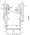
- FIG. 1 is a side view of the wheelchair.
- FIG. 2 is a plan view of the wheelchair.
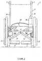
- FIG. 3 is a rear view of the wheelchair.
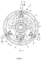
- FIG. 4 is an axial view of the wheel hub portion of the wheelchair with its cover removed.
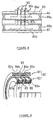
- FIG. 5 is a cross-sectional view taken along the line V-V in FIG. 4.
- FIGs. 6 through 9 are drawings showing a rotary transformer.
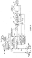
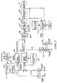
- FIG. 10 shows a system constitution for an assist power control device.
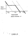
- FIGs. 11 through 13 are characteristic graphs for describing the control function.
- the power-assisted wheelchair 1 of this embodiment is made by adding a power assist system to an existing manual wheelchair of the folding type.
- the wheelchair 1 comprises left and right wheels or driving wheels removably attached to the left and right hands of the vehicle body. Front and rear parts of the pipe frame 3 of the vehicle body are supported with paired right and left casters 4 and wheels 2 for free rolling.
- a seat 5 (Refer to FIGs. 2 and 3) made of cloth for a rider to sit on is stretched in the center of the frame 3.
- the frame 3 has paired front and rear cross members 3a.
- the X-shaped cross members 3a are pivoted at their intersection by means of a shaft 6.
- Paired right and left handle arms 3b are erected in the rear part of the frame 3.
- the upper ends of the handle arms 3b are bent rearward and provided with grips 7 for a tending person.
- Paired right and left arms 3c extend from the middle height position of the handle arms 3b of the frame 3 horizontally forward of the vehicle body and then bend downward at generally right angles, with their ends provided with casters 4 for free rolling.
- a main switch 8 is attached to the upper part of the vertically bent portion of the right hand (as seen from a seated user) arm 3c.
- Front ends of paired right and left seat pipes 3d disposed below the arms 3c extend obliquely down forward, with their extended ends (fore-ends) provided with paired left and right steps 9.
- Each of the wheels 2 is provided with a hand rim assembly 70 for the user to apply rotational force (human power) by hand and with a drive section 20 for outputting motor driving force (assist power) corresponding to the human power inputted from the hand rim assembly 70.
- a boss 11 is screwed into each wheel center portion of the frame 3 and secured with a nut 22a.
- a wheel shaft 22 is inserted into the axial center of the boss 11.
- the wheel shaft 22 is of a hollow shape in the center of which is inserted a shaft 23 which is axially movable. Both end portions of the shaft 23 are respectively formed with head portions 23a and 23b of a larger diameter than that of other portion thereof.
- a coil spring 24 is disposed inside the right hand head portion 23a to urge the shaft 23 toward the right relative to the wheel shaft 22.
- a plural number of balls 25 are held on the wheel shaft 22 so as not to fall out but movable in the radial direction.
- the balls 25 are pushed radially outward with the larger diameter portion of the head portion 23a slightly beyond the outside circumference of the wheel shaft 22 so that the wheel shaft 22 does not come off the boss 11. Also, the wheel shaft 22 may be drawn out of the boss 11 to the left as seen in FIG. 2 by moving the shaft 23 to the left relative to the wheel shaft 22 so that the small diameter portion of the head portion 23a moves to the position of the balls 25 and the balls 25 may move inward.
- the wheel shaft 22 passes through and supports the central portion of a fixing plate 30 which is of a generally cylindrical shape with a bottom and has a rotation stop member (not shown) which engages with the frame 3 to prevent the fixing plate 30 from rotating.
- the wheel shaft 22 supports for free rotation through a bearing 51 a hub 50 of a generally cylindrical shape with a bottom as a rotating side member.
- An internal gear 52 is secured to the inside surface of the hub 50.
- the internal gear 52 engages with an intermediate gear 36a formed integrally with an intermediate shaft 36 which is supported for rotation on the bottom surface of the fixing plate 30 as a fixed side member.
- the intermediate shaft 36 is driven for rotation with a driving motor 31 (Refer to FIG. 3) attached to the fixing plate 30 through a pulley 33 secured to the intermediate shaft 36 and a belt.
- the motor 31 is a DC motor of permanent magnet type.
- the hand rim assembly 70 serves to transmit the torque applied by the user on the hand rim 13 to the hub 50 and at the same time to detect the applied torque. Now the mechanism for transmitting the torque applied by the user will be described.
- FIGs. 4 and 5 show a disk 71 as a central part of the hand rim assembly 70.
- the disk 71 comprises an inner ring 71a portion and an outer ring portion 71b interconnected through three spoke portions 71c, and secured to the hand rim 13 through three spoke pipes 15. Also, the disk 71 is supported for relative rotation on the boss portion 50a of the hub 50 through a bush 55.
- a potentiometer 72 is disposed between the spoke portions 71c and 71c, and secured to the outside surface of the bottom portion 50b of the hub 50 so that its radial position is adjustable.
- the input shaft 72a of the potentiometer 72 projects to the inside of the bottom portion 50b.
- a lever 73 having an elongate hole 73a is attached to the projecting portion of the input shaft 72a.
- a pin 53 secured to the disk 71 is inserted into the elongate hole 73a of the lever 73.
- a spring guide 54 is disposed in a rectangular hole 71d formed in the spoke portion 71c and bolt-secured to the bottom portion 50b of the hub 50.
- a slider 57 and a coil spring 56 with its both ends defined by the spring guide 54 and the bottom portion 50b are accommodated in the spring guide 54. Both ends of the coil spring 56 are in contact with the inside edges of the rectangular hole 71d of the spoke portion 71 through sliders 57.
- a plastic material-made damper member 58 serves to prevent rattle between the hub 50 and the disk 71.
- the damper member 58 is installed inside a recess 54a formed in the spring guide 54 and opposes the outer ring portion 71b of the disk 71. When a bolt 58a is screwed in, the damper member 58 comes into sliding contact with the outer ring portion 71b to prevent to prevent rattle between the hub 50 and the disk 71.
- FIG. 5 shows a cover 71e for covering the potentiometer 72 and others. In FIG. 4, the cover 71e is removed.
- the symbol 100 denotes a controller disposed on the inside surface of the bottom portion 30b of the fixing plate 30, which will be described later.
- a differential rotation transformer 80 comprises; an outer transformer 81 attached to the boss portion 30a in the center of the fixing plate 30, and an inner transformer 82 attached to the boss portion 50a of the hub 50.
- the outer transformer 81 comprises a cylindrical bobbin 83 made of a nonmagnetic, insulating plastic material, with its outside cylindrical surface recess-formed with two winding grooves 83a and 83b, and primary coils 84a and 84b wound in the winding grooves 83a and 83b.
- the inner transformer 82 comprises a cylindrical core 85 made of a magnetic material (metallic material such as mild steel), with its outside cylindrical surface recess-formed with two winding grooves 85a and 85b, and secondary coils 89a and 89b wound in the winding grooves 85a and 85b.
- a magnetic material metallic material such as mild steel
- the symbols 86b and 87b denote slits formed in the bobbins 86 and 87, and the symbol 90 denotes a terminal. Ends 89a' and 89b' of the secondary coils 89a and 89b are led out through the slits 86b and 87b and wound on the terminals 90.
- the outer transformer 81 is not provided with a core of a magnetic material having function of shielding external magnetic field and therefore it is preferable to be disposed to restrict magnetic imbalance caused by external metallic parts.
- the center line D of the width of the outer transformer 81 is displaced by a dimension C toward the fixing plate 30 relative to the center line B of the wheel width.
- the width center line D of the outer transformer 81 is made to match with the wheel width centerline B.
- such an arrangement undesirably increases the difference between the distance from the primary coil 84a to the bottom portion 50b of the hub 50 and the distance from the primary coil 84b to the bottom portion 30b of the fixing plate 30.
- the amounts of the human power to the left and right wheels are detected with the left and right potentiometers 72, 72, inputted through the left and tight rotary transformers 80, 80 to the controller 100 which in turn controls power supply to the motors 31 according to specified procedure so that assist power commensurate with the human power is obtained.
- FIG. 10 shows the control function in the left hand wheel 2.
- the assist power control of the device of this embodiment is of a torque control type, or a current control type, in which the assist power from the motor is controlled along the constant voltage characteristic by setting a limit to the duty ratio in the current control loop.
- the constant voltage characteristic of the motor has a negative gradient relative to the revolution.
- an insensitive zone width commensurate with the degree of disability of the user is automatically set on the basis of the history of human power amounts FL, FR (inputs) applied to the hand rims 13, 13 of the left and right wheels 2, 2. Also, it is arranged to permit manual setting.
- the insensitive zone width means the range of human power amount which does not result in the output of the assist power, and it is mainly intended to absorb sensitivity variation in the human power detection device.
- an assist standby time width N1 as the insensitive zone width is selected with the insensitive zone width setting function 101 at the time of electric power turning on or when no human power input is made for a specified period of time.
- a smaller assist time width N2 is selected.
- the reason for setting the assist standby time width N1 to a large value is to confirm the intention of the user requiring an assist power and to prevent the assist power from being accidentally produced.
- the assist time width N2 is selected.
- the reason for setting the assist standby time width N2 to a small value is to assure smooth assist operation.
- the manner of setting the insensitive zone width is not limited to two kinds but may be selected from a plural number of kinds. It is also possible to provide a changing switch, an adjustment knob, etc. for the user to manually change the sizes of the zones.
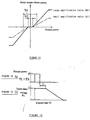
- an insensitive zone is given to the input signal FL, and multiplied by an amplification ratio KL (Refer to FIG. 11) set according to the degree of disability of the user (103).
- amplification ratio KL (Refer to FIG. 11) set according to the degree of disability of the user (103).
- turning component setting means 104 determines a turning torque iL as a turning movement causing component.
- the amplification ratios KLs for the left and right wheels may be different from each other depending on the difference in muscle power strengths between left and right arms of the user.
- center of gravity torque iG is determined as a component causing straight line movement based on a resultant force (FL ⁇ KL + FR ⁇ KR) based on specified amplification ratios of the left hand human power FL and the right hand human power FR.
- a target torque iR is obtained.
- a target current value iREF is determined which is necessary for the motor 31 to produce the target torque iR.
- a compensation amount is determined with a PID control circuit 107.
- a duty limiter 108 performs voltage checking, which will be described later, and a specified duty ratio is outputted.
- a bipolar power amplifier 109 converts the control signal (duty ratio) into an actual current. In this way, the assist current is supplied to the motor 31.
- the assist current is determined according to the amount of the human power, the current does not become zero immediately when the human power supply stops, but remains unchanged for a specified period of time (for example t1) and thereafter decreases gradually.
- an upper limit voltage setting means 111 and a lower limit voltage setting means 112 set an upper limit voltage E1 and a lower limit voltage E2.
- the voltage determined from the duty ratio in the duty limiter 108 is limited within the upper and lower limit voltages E1 and E2, and outputted.
- the rotation speed of the motor 31, or the vehicle speed is limited with the upper and lower limit voltages.
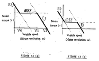
- FIG. 13 indicates that the upper limit voltage E1 and the lower limit voltage E2 specify the rotation speed of the motor or the vehicle speed, and that the target current iREF specifies the motor torque.
- the upper and lower limit voltages E1 and E2, or V1 and V2 are initially set to specified values according to the amounts of the human power (for example the values shown in FIG. 13a) and then as shown in FIG. 12, for a specified period of time t1 after the stop of the human power supply they are maintained at the values (the values shown in FIG. 13a) set before the stop of human power application, and gradually decreased with the lapse of time to the value, for example, shown in FIG. 13b. This process is repeated at each input of human power.
- the assist power output from the motor 31 varies as follows: Under the state of the actual vehicle speed in forward movement from the fourth preset vehicle speed of V4 to the first preset vehicle speed of V1, the current for the assist power is maintained at the target current value of iREF. When the actual vehicle speed exceeds the first preset vehicle speed of V1, the current is gradually decreased with the increase in the vehicle speed to substantially zero at the second preset vehicle speed of V2. When the actual vehicle speed further increases beyond the second preset vehicle speed of V2, the motor 31 serves as a load.
- the assist power output from the motor 31 is increased with the decrease in the vehicle speed when the actual vehicle speed in forward movement decreases below the fourth preset vehicle speed of V4. This means that, for example, even if the human power input is stopped when actual the vehicle speed is below V4, the assist power is increased for the period of time t1 to maintain the actual vehicle speed at V4, and then the actual vehicle speed gradually decreases.
- the insensitive zone width is made in two steps: it is made as the assist standby time width N1 at the time of electric power turning on or when no human power input is made for a specified period of time, and once the human power exceeds the assist standby time width N1, it is made as the assist time width N2, where N1 > N2.
- the assist time width N2 is selected. Since the value of N2 is set small, smooth assist operation may be performed according to the history of input.
- the insensitive zone width may be adjusted by the use or using an external switch, adjustment knob, etc. In this way, the insensitive zone width may be set according to the degree of disability of the user to start the supply of the assist power more smoothly, which is another advantage.
- this embodiment is arranged that, every time human power is applied, the upper limit voltage E1 supplied to the motor 31 is reset to the value corresponding to the amount of the human power, the vehicle speed is limited with the upper limit voltage E1 so that the problem of excessive vehicle speed may be avoided.
- the motor 31 becomes a load so that the problem of excessive speed on the downhill may be avoided.
- the target current iREF and the upper limit voltage E1 are controlled to be maintained at values set before the stop of human power supply, for a specified period of time t1 after the supply of human power F is stopped, and thereafter decreased with the lapse of time. As a result, problems are avoided such as; the motor becomes a load when the vehicle is coasting during a pause of human power input, or sudden deceleration on an uphill upon stopping the human power input.
- the assist power is increased with the decrease in the actual vehicle speed.
- the V4 is set to zero. So it is possible for the rider to change the gripping position on the hand rim without haste and resume supplying human power input. This improves ease of use.
- the holding time duration in such a case is dependent on the setting of the upper limit voltage holding time t1. After that holding time, the amount of the assist power decreases gradually.
- the assist power amount is limited by limiting the upper limit voltage E1 and the lower limit voltage E2, and as a result, the vehicle speed is controlled.
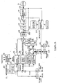
- FIG. 14 Such an arrangement is shown in FIG. 14 as the second embodiment.
- the same symbols denote the same or like parts as those in FIG. 10.
- upper limit speed setting means 211 and lower limit speed setting means 212 set an upper limit speed 1 and a lower limit speed 2 according to the input human power amounts FL and FR.
- the upper limit speed 1 corresponds to the second preset vehicle speed of V2 in FIG. 13, and the lower limit speed 2 to the fourth preset vehicle speed of V4.
- vehicle speed calculation means 213 calculates left and right wheel speeds L and R.
- the type of this embodiment is more favorable in terms of cost, weight, and layout space.
- the left wheel speed L and the right wheel speed R are added and divided by two to obtain the center of gravity speed G.
- the G is then compared with the upper and lower limit speeds 1 and 2.
- Gain providing means 214 and 215 determine torque to be increased or decreased according to the difference; when the center of gravity speed G is greater than the upper limit speed 1, the torque to be decreased is determined as -i1, and when the center of gravity speed G is smaller than the lower limit speed 2, the torque to be decreased is determined as +i2.
- the increment torque +i2 and the decrement torque -i1 are added to the turning torque and the center of gravity torque and in the step 106, the target current iREF is determined.
- the second embodiment can further provide an effect of a wide usable duty ratio in the PWM control.
- FIGs. 15 and 16 show a third embodiment in which the motor 31 serves as a load when the vehicle speed exceeds a third preset vehicle speed of V3 which is greater than the V2.
- the same symbols denote the same or like parts as those in FIGs. 10 and 14.
- preset vehicle speed calculation means 216 calculates at each inputting of human power , the first through fourth preset vehicle speeds of V1 through V4 according to the human power amounts FL, FR applied to the left and right wheels. In this case, the greater are the human power amounts, the greater are set the first through fourth preset vehicle speeds of V1 through V4, and vice versa.
- the center of gravity component setting means 105 calculates a center of gravity torque iG according to the first through fourth preset vehicle speeds and the detected center of gravity speed G. The result is added to the turning torque iL in the step 106 to determine the target current iREF.
- the target current iREF is determined so that the assist power is commensurate with the human power when the center of gravity speed G is between the fourth and first preset vehicle speeds of V4 and V1, the assist power is gradually decreased when the center of gravity speed G is between the first and second preset vehicle speeds of V1 and V2, the assist power is made zero when the center of gravity speed G is between the second and third preset vehicle speeds of V2 and V3, and the load gradually increases as the center of gravity speed G increases beyond the third preset vehicle speed of V3.
- the motor 31 does not serve as a load immediately beyond the second preset vehicle speed of V2 and the wheelchair may coast until it reaches the third preset vehicle speed of V3.
Priority Applications (4)
| Application Number | Priority Date | Filing Date | Title |
|---|---|---|---|
| JP8256937A JPH1099379A (ja) | 1996-09-27 | 1996-09-27 | 補助動力付き車椅子 |
| US09/046,193 US6354390B1 (en) | 1996-09-27 | 1998-03-23 | Power assisted wheelchair |
| EP98105527A EP0945112B1 (fr) | 1996-09-27 | 1998-03-26 | Fauteuil roulant à assistance motorisée et son procédé de fonctionnement |
| DE69819868T DE69819868T2 (de) | 1998-03-26 | 1998-03-26 | Rollstuhl mit Hilfsantrieb und Verfahren zu seinem Betrieb |
Applications Claiming Priority (3)
| Application Number | Priority Date | Filing Date | Title |
|---|---|---|---|
| JP8256937A JPH1099379A (ja) | 1996-09-27 | 1996-09-27 | 補助動力付き車椅子 |
| US09/046,193 US6354390B1 (en) | 1996-09-27 | 1998-03-23 | Power assisted wheelchair |
| EP98105527A EP0945112B1 (fr) | 1996-09-27 | 1998-03-26 | Fauteuil roulant à assistance motorisée et son procédé de fonctionnement |
Publications (2)
| Publication Number | Publication Date |
|---|---|
| EP0945112A1 true EP0945112A1 (fr) | 1999-09-29 |
| EP0945112B1 EP0945112B1 (fr) | 2003-11-19 |
Family
ID=27239042
Family Applications (1)
| Application Number | Title | Priority Date | Filing Date |
|---|---|---|---|
| EP98105527A Expired - Lifetime EP0945112B1 (fr) | 1996-09-27 | 1998-03-26 | Fauteuil roulant à assistance motorisée et son procédé de fonctionnement |
Country Status (3)
| Country | Link |
|---|---|
| US (1) | US6354390B1 (fr) |
| EP (1) | EP0945112B1 (fr) |
| JP (1) | JPH1099379A (fr) |
Cited By (5)
| Publication number | Priority date | Publication date | Assignee | Title |
|---|---|---|---|---|
| US6459962B2 (en) | 1999-08-31 | 2002-10-01 | Deltaglide, Inc. | Power assist vehicle |
| US6946650B2 (en) | 2002-03-04 | 2005-09-20 | Independence Technology, L.L.C. | Sensor |
| EP2649973A1 (fr) * | 2012-04-12 | 2013-10-16 | AAT Alber Antriebstechnik GmbH | Dispositif d'entraînement auxiliaire pour fauteuils roulants |
| EP3682859A4 (fr) * | 2017-09-14 | 2020-09-09 | Yamaha Hatsudoki Kabushiki Kaisha | Fauteuil roulant à assistance électrique, unité d'assistance électrique pour fauteuil roulant, dispositif et procédé de commande de fauteuil roulant à assistance électrique, programme et terminal |
| GB2592137A (en) * | 2020-01-31 | 2021-08-18 | Phoenix Instinct Ltd | Advanced wheelchair |
Families Citing this family (31)
| Publication number | Priority date | Publication date | Assignee | Title |
|---|---|---|---|---|
| JP2001314453A (ja) * | 2000-02-28 | 2001-11-13 | Yamaha Motor Co Ltd | 電動車両の駆動ユニット |
| US20040104321A1 (en) * | 2002-08-06 | 2004-06-03 | Marsolais Thomas R. | Adjustable connector for I.V. poles and medical devices |
| DE102005006574B3 (de) * | 2005-02-11 | 2006-09-21 | Barthelt, Hans-Peter, Dipl.-Ing. | Rollstuhl mit Fernbedienung |
| US7624826B2 (en) * | 2005-07-08 | 2009-12-01 | Zhao Tianyun | Portable power-saving and foldable electric wheel chair |
| US7403844B2 (en) | 2005-08-31 | 2008-07-22 | Invacare Corporation | Method and apparatus for programming parameters of a power driven wheelchair for a plurality of drive settings |
| AU2006284768A1 (en) * | 2005-08-31 | 2007-03-08 | Invacare Corporation | Adjustable mount for controller of power driven wheelchair |
| US20070050096A1 (en) * | 2005-08-31 | 2007-03-01 | Invacare Corporation | Programmable actuator controller for power positioning seat or leg support of a wheelchair |
| DE102005043524B3 (de) * | 2005-09-13 | 2007-04-26 | Pihsiang Machinery Mfg. Co., Ltd., Hsin Feng Hsiang | Betätigungsmechanismus eines Hilfsmotors von Rollstühlen |
| NO20054431A (no) * | 2005-09-26 | 2007-01-15 | Pihsiang Machinery Mfg Co Ltd | Startapparat for hjelpemotor til en rullestol. |
| US20110130940A1 (en) * | 2008-05-23 | 2011-06-02 | Foundacion Fatronik | Wheelchair and method for correcting the guidance of a wheelchair |
| US8851213B1 (en) * | 2009-12-24 | 2014-10-07 | Bryan Bradley Jones | Powered wheel chair with automatic emergency stopping |
| TW201121531A (en) * | 2009-12-31 | 2011-07-01 | xiang-ling Xu | Auxiliary driving device for wheelchair. |
| US8496080B2 (en) | 2010-09-30 | 2013-07-30 | National Taiwan University | Wheel driven mechanism |
| EP3260101B1 (fr) * | 2011-07-06 | 2021-12-08 | Max Mobility, LLC | Système d'aide motorisée basé sur le mouvement pour fauteuils roulants |
| US9144525B2 (en) | 2013-03-14 | 2015-09-29 | Max Mobility, Llc. | Motion assistance system for wheelchairs |
| US9301895B2 (en) * | 2013-03-15 | 2016-04-05 | Stryker Corporation | Medical support apparatus |
| EP3017798B1 (fr) * | 2013-07-04 | 2022-03-23 | Yamaha Hatsudoki Kabushiki Kaisha | Dispositif alimenté électriquement pour fauteuils roulants, fauteuil roulant électrique comprenant ledit dispositif alimenté électriquement pour fauteuils roulants, et procédé de surveillance d'entraînement pour fauteuils roulants électriques |
| US20160313758A1 (en) * | 2013-12-17 | 2016-10-27 | Red Milawa Pty Ltd | Device and system for controlling a transport vehicle |
| US11294415B2 (en) | 2013-12-17 | 2022-04-05 | Red Milawa Pty Ltd | Device and system for controlling a transport vehicle |
| TWI607926B (zh) * | 2014-08-29 | 2017-12-11 | 國立清華大學 | 位移設備及動力輔助系統 |
| US9795524B2 (en) | 2015-02-24 | 2017-10-24 | Max Mobility, Llc | Assistive driving system for a wheelchair |
| CN106985608A (zh) * | 2017-04-14 | 2017-07-28 | 常州市吉庆机电有限公司 | 一种万向轮 |
| US11432977B2 (en) * | 2017-06-26 | 2022-09-06 | Yamaha Hatsudoki Kabushiki Kaisha | Power assist wheelchair, power assist unit for wheelchair, control device for power assist wheelchair, control method for power assist wheelchair, and program |
| WO2019075081A1 (fr) | 2017-10-12 | 2019-04-18 | The Center for Discovery, Inc. | Ensemble d'entraînement pour un fauteuil roulant à fonctionnement manuel et ses procédés d'utilisation |
| CN107908127B (zh) * | 2017-10-23 | 2020-12-01 | 广州视源电子科技股份有限公司 | 电动轮椅控制方法、装置及计算机可读存储介质 |
| CN109895136A (zh) * | 2017-12-10 | 2019-06-18 | 湘潭宏远电子科技有限公司 | 一种机器人平衡装置 |
| US10167051B1 (en) | 2017-12-12 | 2019-01-01 | Max Mobility, Llc | Assistive driving system for a wheelchair and method for controlling assistive driving system |
| DE102018117476A1 (de) * | 2018-07-19 | 2020-01-23 | Sunrise Medical Gmbh | Montageeinheit, Lenkrollenanordnung und Rollstuhl |
| TWI676472B (zh) * | 2018-10-05 | 2019-11-11 | 財團法人工業技術研究院 | 助力輪 |
| FR3101771A1 (fr) * | 2019-10-14 | 2021-04-16 | Electricite De France | Procédé de contrôle d’un dispositif d’assistance électrique |
| US11660240B2 (en) * | 2020-06-05 | 2023-05-30 | Toyota Motor North America, Inc. | Wheelchair systems and methods enabling fine manual motion control |
Citations (3)
| Publication number | Priority date | Publication date | Assignee | Title |
|---|---|---|---|---|
| EP0687454A1 (fr) * | 1994-06-16 | 1995-12-20 | Yamaha Hatsudoki Kabushiki Kaisha | Véhicule à propulsion assistée et méthode de commande dudit véhicule |
| EP0776647A1 (fr) * | 1995-06-20 | 1997-06-04 | Yamaha Hatsudoki Kabushiki Kaisha | Chaise roulante manuelle et electrique |
| EP0790049A2 (fr) * | 1996-02-14 | 1997-08-20 | Yamaha Hatsudoki Kabushiki Kaisha | Fauteuil roulant |
Family Cites Families (16)
| Publication number | Priority date | Publication date | Assignee | Title |
|---|---|---|---|---|
| US4021690A (en) * | 1975-05-30 | 1977-05-03 | Frank Burton | Wheel borne counter rotating disc alternator |
| US4062421A (en) * | 1976-02-25 | 1977-12-13 | Weber Milton N | Bicycle drive system |
| US4634941A (en) * | 1981-04-15 | 1987-01-06 | Invacare Corporation | Electric wheelchair with improved control circuit |
| US4387325A (en) * | 1981-04-15 | 1983-06-07 | Invacare Corporation | Electric wheelchair with speed control circuit |
| AT384947B (de) * | 1984-02-24 | 1988-01-25 | Haubenwallner Gerhard | Von einer energiequelle versorgter antrieb fuer raeder, insbesondere von rollstuehlen |
| US5078227A (en) * | 1989-06-18 | 1992-01-07 | S. A. E. Akikim | Auxiliary drive for vehicles |
| US5234066A (en) * | 1990-11-13 | 1993-08-10 | Staodyn, Inc. | Power-assisted wheelchair |
| US5222567A (en) * | 1991-04-26 | 1993-06-29 | Genus Inc. | Power assist device for a wheelchair |
| DE4127257A1 (de) * | 1991-08-17 | 1993-02-18 | Haas & Alber Haustechnik Und A | Kleinfahrzeug, insbesondere rollstuhl mit faltbarem stuhlgestell |
| US5199520A (en) * | 1991-12-11 | 1993-04-06 | Sen Jung Chen | Wheeled chair |
| US5555949A (en) * | 1992-02-18 | 1996-09-17 | Cerebral Palsy Research Foundation Of Kansas | Electricaly operable wheelchair having a controller responsive to different types of inputs |
| US5366037A (en) * | 1992-11-23 | 1994-11-22 | Invacare Corporation | Powered wheelchair having drive motors integrated into driven wheels |
| US5427193A (en) * | 1993-04-19 | 1995-06-27 | Datatran Inc. | Drive system for wheelchairs or the like |
| US5450915A (en) * | 1993-12-20 | 1995-09-19 | Li; I-Ho | Electric motor-in-wheel |
| US5755304A (en) * | 1994-08-08 | 1998-05-26 | Yamaha Hatsudoki Kabushiki Kaisha | Electric motor operated wheel |
| JP3691132B2 (ja) * | 1995-10-31 | 2005-08-31 | 三洋電機株式会社 | アシスト式乗り物 |
-
1996
- 1996-09-27 JP JP8256937A patent/JPH1099379A/ja not_active Withdrawn
-
1998
- 1998-03-23 US US09/046,193 patent/US6354390B1/en not_active Expired - Lifetime
- 1998-03-26 EP EP98105527A patent/EP0945112B1/fr not_active Expired - Lifetime
Patent Citations (3)
| Publication number | Priority date | Publication date | Assignee | Title |
|---|---|---|---|---|
| EP0687454A1 (fr) * | 1994-06-16 | 1995-12-20 | Yamaha Hatsudoki Kabushiki Kaisha | Véhicule à propulsion assistée et méthode de commande dudit véhicule |
| EP0776647A1 (fr) * | 1995-06-20 | 1997-06-04 | Yamaha Hatsudoki Kabushiki Kaisha | Chaise roulante manuelle et electrique |
| EP0790049A2 (fr) * | 1996-02-14 | 1997-08-20 | Yamaha Hatsudoki Kabushiki Kaisha | Fauteuil roulant |
Cited By (7)
| Publication number | Priority date | Publication date | Assignee | Title |
|---|---|---|---|---|
| US6459962B2 (en) | 1999-08-31 | 2002-10-01 | Deltaglide, Inc. | Power assist vehicle |
| US6946650B2 (en) | 2002-03-04 | 2005-09-20 | Independence Technology, L.L.C. | Sensor |
| EP2649973A1 (fr) * | 2012-04-12 | 2013-10-16 | AAT Alber Antriebstechnik GmbH | Dispositif d'entraînement auxiliaire pour fauteuils roulants |
| EP3682859A4 (fr) * | 2017-09-14 | 2020-09-09 | Yamaha Hatsudoki Kabushiki Kaisha | Fauteuil roulant à assistance électrique, unité d'assistance électrique pour fauteuil roulant, dispositif et procédé de commande de fauteuil roulant à assistance électrique, programme et terminal |
| US11304862B2 (en) | 2017-09-14 | 2022-04-19 | Yamaha Hatsudoki Kabushiki Kaisha | Power assist wheelchair, power assist unit for wheelchair, control device for power assist wheelchair, control method for power assist wheelchair, program, and terminal |
| GB2592137A (en) * | 2020-01-31 | 2021-08-18 | Phoenix Instinct Ltd | Advanced wheelchair |
| GB2592137B (en) * | 2020-01-31 | 2022-04-27 | Phoenix Instinct Ltd | Advanced wheelchair |
Also Published As
| Publication number | Publication date |
|---|---|
| US6354390B1 (en) | 2002-03-12 |
| EP0945112B1 (fr) | 2003-11-19 |
| JPH1099379A (ja) | 1998-04-21 |
Similar Documents
| Publication | Publication Date | Title |
|---|---|---|
| EP0945112B1 (fr) | Fauteuil roulant à assistance motorisée et son procédé de fonctionnement | |
| US6230831B1 (en) | Wheel chair with auxiliary power | |
| EP0790049B1 (fr) | Fauteuil roulant et methode de contrôle pour un moteur auxiliaire | |
| EP0687454B1 (fr) | Véhicule à propulsion assistée et méthode de commande dudit véhicule | |
| US6320336B1 (en) | Bicycle with power assisting function | |
| US7840327B2 (en) | Drive assistance device for a wheel chair and a wheel chair having a drive assistance device | |
| JPH1059260A (ja) | 電動車用モータのトルク制限装置 | |
| JPH09263290A (ja) | 電動自転車 | |
| KR20020070650A (ko) | 전동 보조식 자전거의 제어장치 | |
| JPH04100790A (ja) | 電動モータ付き人力駆動装置 | |
| JPH09123984A (ja) | アシスト式乗り物 | |
| US20020021106A1 (en) | Control system for small electric motor vehicle | |
| EP0706909A2 (fr) | Dispositif de propulsion électrique, en particulier dans des véhicules avec une, deux ou plusieur roues motrices et véhicule avec un tel dispositif de propulsion | |
| JP4100761B2 (ja) | 補助動力付き車椅子 | |
| JPH1081290A (ja) | トルク補助式電動自転車 | |
| JPH06141401A (ja) | 電動車両用駆動装置 | |
| JPH08113184A (ja) | 電動自転車 | |
| JP2001080570A (ja) | 補助動力付き車両 | |
| JP3743367B2 (ja) | 自動走行車の速度制御装置 | |
| JP5012595B2 (ja) | 電磁誘導式ゴルフカートの走行制御方式 | |
| JP4814065B2 (ja) | 電動車両の制御装置 | |
| JP4350811B2 (ja) | 補助動力式車椅子 | |
| JP2514461B2 (ja) | リタ―ダ付オ―トクル―ズ装置 | |
| JPH1099380A (ja) | 補助動力付き車椅子 | |
| JP3929122B2 (ja) | 補助動力式車椅子 |
Legal Events
| Date | Code | Title | Description |
|---|---|---|---|
| PUAI | Public reference made under article 153(3) epc to a published international application that has entered the european phase |
Free format text: ORIGINAL CODE: 0009012 |
|
| AK | Designated contracting states |
Kind code of ref document: A1 Designated state(s): DE DK FR GB NL SE |
|
| AX | Request for extension of the european patent |
Free format text: AL;LT;LV;MK;RO;SI |
|
| 17P | Request for examination filed |
Effective date: 20000324 |
|
| AKX | Designation fees paid |
Free format text: DE DK FR GB NL SE |
|
| GRAH | Despatch of communication of intention to grant a patent |
Free format text: ORIGINAL CODE: EPIDOS IGRA |
|
| GRAS | Grant fee paid |
Free format text: ORIGINAL CODE: EPIDOSNIGR3 |
|
| GRAA | (expected) grant |
Free format text: ORIGINAL CODE: 0009210 |
|
| AK | Designated contracting states |
Kind code of ref document: B1 Designated state(s): DE DK FR GB NL SE |
|
| PG25 | Lapsed in a contracting state [announced via postgrant information from national office to epo] |
Ref country code: NL Free format text: LAPSE BECAUSE OF FAILURE TO SUBMIT A TRANSLATION OF THE DESCRIPTION OR TO PAY THE FEE WITHIN THE PRESCRIBED TIME-LIMIT Effective date: 20031119 Ref country code: FR Free format text: LAPSE BECAUSE OF FAILURE TO SUBMIT A TRANSLATION OF THE DESCRIPTION OR TO PAY THE FEE WITHIN THE PRESCRIBED TIME-LIMIT Effective date: 20031119 |
|
| REG | Reference to a national code |
Ref country code: GB Ref legal event code: FG4D |
|
| REF | Corresponds to: |
Ref document number: 69819868 Country of ref document: DE Date of ref document: 20031224 Kind code of ref document: P |
|
| PG25 | Lapsed in a contracting state [announced via postgrant information from national office to epo] |
Ref country code: SE Free format text: LAPSE BECAUSE OF FAILURE TO SUBMIT A TRANSLATION OF THE DESCRIPTION OR TO PAY THE FEE WITHIN THE PRESCRIBED TIME-LIMIT Effective date: 20040219 Ref country code: DK Free format text: LAPSE BECAUSE OF FAILURE TO SUBMIT A TRANSLATION OF THE DESCRIPTION OR TO PAY THE FEE WITHIN THE PRESCRIBED TIME-LIMIT Effective date: 20040219 |
|
| NLV1 | Nl: lapsed or annulled due to failure to fulfill the requirements of art. 29p and 29m of the patents act | ||
| PLBE | No opposition filed within time limit |
Free format text: ORIGINAL CODE: 0009261 |
|
| STAA | Information on the status of an ep patent application or granted ep patent |
Free format text: STATUS: NO OPPOSITION FILED WITHIN TIME LIMIT |
|
| 26N | No opposition filed |
Effective date: 20040820 |
|
| EN | Fr: translation not filed | ||
| PGFP | Annual fee paid to national office [announced via postgrant information from national office to epo] |
Ref country code: DE Payment date: 20170322 Year of fee payment: 20 |
|
| PGFP | Annual fee paid to national office [announced via postgrant information from national office to epo] |
Ref country code: GB Payment date: 20170322 Year of fee payment: 20 |
|
| REG | Reference to a national code |
Ref country code: DE Ref legal event code: R071 Ref document number: 69819868 Country of ref document: DE |
|
| REG | Reference to a national code |
Ref country code: GB Ref legal event code: PE20 Expiry date: 20180325 |
|
| PG25 | Lapsed in a contracting state [announced via postgrant information from national office to epo] |
Ref country code: GB Free format text: LAPSE BECAUSE OF EXPIRATION OF PROTECTION Effective date: 20180325 |