EP0944112B1 - Halogenglühlampe, elektrische Lampe und Verfahren zur Herstellung einer Halogenglühlampe - Google Patents
Halogenglühlampe, elektrische Lampe und Verfahren zur Herstellung einer Halogenglühlampe Download PDFInfo
- Publication number
- EP0944112B1 EP0944112B1 EP99103807A EP99103807A EP0944112B1 EP 0944112 B1 EP0944112 B1 EP 0944112B1 EP 99103807 A EP99103807 A EP 99103807A EP 99103807 A EP99103807 A EP 99103807A EP 0944112 B1 EP0944112 B1 EP 0944112B1
- Authority
- EP
- European Patent Office
- Prior art keywords
- luminous element
- incandescent lamp
- halogen incandescent
- foil
- power supply
- Prior art date
- Legal status (The legal status is an assumption and is not a legal conclusion. Google has not performed a legal analysis and makes no representation as to the accuracy of the status listed.)
- Expired - Lifetime
Links
- 229910052736 halogen Inorganic materials 0.000 title claims description 26
- 150000002367 halogens Chemical class 0.000 title claims description 26
- 238000004519 manufacturing process Methods 0.000 title claims description 7
- 238000000034 method Methods 0.000 title claims description 4
- 239000011888 foil Substances 0.000 claims description 19
- 239000012780 transparent material Substances 0.000 claims 2
- 210000002414 leg Anatomy 0.000 description 32
- ZOKXTWBITQBERF-UHFFFAOYSA-N Molybdenum Chemical compound [Mo] ZOKXTWBITQBERF-UHFFFAOYSA-N 0.000 description 4
- 229910052750 molybdenum Inorganic materials 0.000 description 4
- 239000011733 molybdenum Substances 0.000 description 4
- 238000003466 welding Methods 0.000 description 4
- 239000000463 material Substances 0.000 description 3
- 241000842962 Apoda limacodes Species 0.000 description 2
- XKRFYHLGVUSROY-UHFFFAOYSA-N Argon Chemical compound [Ar] XKRFYHLGVUSROY-UHFFFAOYSA-N 0.000 description 2
- VYPSYNLAJGMNEJ-UHFFFAOYSA-N Silicium dioxide Chemical compound O=[Si]=O VYPSYNLAJGMNEJ-UHFFFAOYSA-N 0.000 description 2
- 230000001154 acute effect Effects 0.000 description 2
- BASFCYQUMIYNBI-UHFFFAOYSA-N platinum Chemical compound [Pt] BASFCYQUMIYNBI-UHFFFAOYSA-N 0.000 description 2
- WFKWXMTUELFFGS-UHFFFAOYSA-N tungsten Chemical compound [W] WFKWXMTUELFFGS-UHFFFAOYSA-N 0.000 description 2
- 229910052721 tungsten Inorganic materials 0.000 description 2
- 239000010937 tungsten Substances 0.000 description 2
- 208000034656 Contusions Diseases 0.000 description 1
- 239000000654 additive Substances 0.000 description 1
- 230000000996 additive effect Effects 0.000 description 1
- 229910052786 argon Inorganic materials 0.000 description 1
- 208000034526 bruise Diseases 0.000 description 1
- 239000000919 ceramic Substances 0.000 description 1
- 238000010276 construction Methods 0.000 description 1
- 230000001419 dependent effect Effects 0.000 description 1
- 238000003780 insertion Methods 0.000 description 1
- 230000037431 insertion Effects 0.000 description 1
- 229910001507 metal halide Inorganic materials 0.000 description 1
- 150000005309 metal halides Chemical class 0.000 description 1
- 230000003647 oxidation Effects 0.000 description 1
- 238000007254 oxidation reaction Methods 0.000 description 1
- 229910052697 platinum Inorganic materials 0.000 description 1
- 210000000689 upper leg Anatomy 0.000 description 1
- 238000004804 winding Methods 0.000 description 1
Images

Classifications
-
- H—ELECTRICITY
- H01—ELECTRIC ELEMENTS
- H01K—ELECTRIC INCANDESCENT LAMPS
- H01K1/00—Details
- H01K1/40—Leading-in conductors
-
- H—ELECTRICITY
- H01—ELECTRIC ELEMENTS
- H01J—ELECTRIC DISCHARGE TUBES OR DISCHARGE LAMPS
- H01J61/00—Gas-discharge or vapour-discharge lamps
- H01J61/02—Details
- H01J61/36—Seals between parts of vessels; Seals for leading-in conductors; Leading-in conductors
-
- H—ELECTRICITY
- H01—ELECTRIC ELEMENTS
- H01K—ELECTRIC INCANDESCENT LAMPS
- H01K1/00—Details
- H01K1/02—Incandescent bodies
- H01K1/04—Incandescent bodies characterised by the material thereof
- H01K1/06—Carbon bodies
-
- H—ELECTRICITY
- H01—ELECTRIC ELEMENTS
- H01K—ELECTRIC INCANDESCENT LAMPS
- H01K1/00—Details
- H01K1/18—Mountings or supports for the incandescent body
-
- H—ELECTRICITY
- H01—ELECTRIC ELEMENTS
- H01K—ELECTRIC INCANDESCENT LAMPS
- H01K3/00—Apparatus or processes adapted to the manufacture, installing, removal, or maintenance of incandescent lamps or parts thereof
- H01K3/06—Attaching of incandescent bodies to mount
Definitions
- the invention is based on a halogen incandescent lamp according to the preamble of claim 1. These are in particular squeezed on two sides Incandescent lamps with an axially arranged filament.
- a generic halogen incandescent lamp is already known from the document EP-A 475 508 known.
- An end region of the cylindrical filament is through a power supply inserted therein is mechanically supported by the Power supply is bent asymmetrically in one plane. In particular is they shaped so that on a first axially parallel leg of the Power supply a second leg is formed with a free end.
- the free end hooks behind a turn of the filament that is spaced from the end of the filament is one-sided, while the first leg opposite the free end on the turns of the filament is applied.
- the film-side end of the power supply is more common on the film Way welded.
- the disadvantage of this construction is that the centering of the filament and the power supply system because of asymmetrical shape of the power supply is not reliably guaranteed is. In addition, the welding process is very time-consuming and costly.
- the present invention is based on a simple design, if possible symmetrical power supply, which is advantageous spring action exerts on the illuminant and thus automatically the centering of the filament ensures.
- the concept of this power supply has the particular advantage that the connection to the film is not by welding, but by mechanical contact. It doesn't just mean that Costs and manufacturing time significantly reduced, but there are also no potential Weaknesses. Previously, an expensive platinum paste had to be used for welding to be used. The area of the welding spot was also previously the Exposed to oxidation, which reduced the lifespan.
- the halogen incandescent lamp according to the invention has a hermetic seal sealed piston made of translucent material on the one Lamp axis defined. Furthermore, it has a preferably axially arranged coiled (and thus cylindrically shaped) filament with two ends and a power supply system that connects to the two end areas of the filament is connected.
- the power supply system includes a film and an inner and outer power supply, the filament side inner end of the power supply the end region of the filament from the inside.
- the foil-side outer end of the power supply is connected to the film.
- the power supply itself is U-shaped bent by two free legs, advantageously loaded with spring force lie in one plane and connected to each other via a straight base are.
- the section on the filament side is at the end of the associated film folded back and forms a fold in which the base is mechanically held is.
- the ends of the free legs protrude into an end region of the filament into it.
- At least one hook part is on one of the free legs to the outside. This hook part engages between two turns of the Filament.
- the area of the folded end portion of the film is normal rectangular.
- Such a folded-over rectangular end section of the film is already known from EP-A 780 883. However, this area is now preferred reduced to at least one or both free corners. This facilitates the automatic hooking of the power supply in the fold of the Foil. This also saves film material.
- the folded one Section is preferably triangular (symmetrical or asymmetrical). However, it can also be rounded, for example. This cheap In principle, the design of the end section of the film is independent of the special way of providing a power supply suspended in the film. In principle, it is for both external and internal power supply suitable. For this special shape of the folded end section with a reduced area therefore becomes independent of the special one The shape of the power supply hooked into it requires protection. This one folded In principle, the end section can also be used with other lamp types (especially discharge lamps with metal halide filling) are used become.
- Each of the two legs preferably has a hook part. This will improved the bracket and ensured the centering even better.
- the legs are usually the same length. However, it is for special applications advantageous to use legs of different lengths.
- the concept according to the invention is particularly good for a halogen incandescent lamp suitable, which is squeezed on two or one side. You can both end areas are supported by a new type of power supply.
- the diameter of the wire is advantageous for the power supply is used, at least as large as the distance between two turns of the filament.
- the bracket is not only by the tension between the two ends of the filament caused, but also or mainly by a clamping intervention of the hook part between two turns of the filament.
- the wire diameter of the power supply is greater than the distance between two Turns of the filament, so that the filament when inserting the Power supply is spread slightly; it is preferably 10 to 30% larger, see above that on the one hand the clamping intervention is easy to accomplish and on the other hand the holding force is still sufficiently safe.
- the hook part preferably protrudes slightly above the lamp outwards.
- the free legs can run straight and axially parallel, which is the easiest is to be produced.
- the legs are shaped so that the width of the film regardless of dimensions of the filament can be selected.
- the legs are either inclined inwards towards the axis, or the two legs point in one particularly preferred embodiment just before the end of the Filament has an inward curvature that defines the distance between the thigh ends reduced. This shape is the end area of the filament ideally adjusted so that the holder and centering of the filament works particularly reliably.
- the hook part preferably forms an outwardly protruding angle to Leg, the hook part at an angle ⁇ between 30 ° and 120 °, in particular about 50 ° to 60 °, is bent relative to the free leg.
- the legs should at least two turns, preferably more than 3 turns, in the end area of the filament are introduced.
- the power supply is mostly made of tungsten or molybdenum.
- the hook part must be designed so that the filament side Width when compressed is always smaller than that Inner diameter of the filament is.
- the length of the two hook parts in the case of their right-angled bend) or their length in projection transverse to the lamp axis (in the event that the hook parts are at an acute angle to the Legs are arranged) may therefore at most half the inner diameter correspond to the cylinder formed by the filament. In the event of of a single hook part is accordingly a length up to the full Inside diameter permitted.
- a method of manufacturing the halogen incandescent lamp described above is based on the fact that the power supply with the two legs initially is squeezed.
- the power supply is in this state introduced the end region of the filament at least two turns.
- the legs snap open when the power supply is relaxed outside and press evenly from the inside against the end area of the Illuminant.
- the hook part (s) press into the space jamming between two turns.
- the tension is the Helix advantageous because it increases the distance between two turns.
- the lamp-side section of the film initially angled only by more than 90 ° (preferably at least 100 °) that there is a fold in the film.
- the internal power supply is in this with its base hooked in and the filament in relation to the foil underneath Tension held. Then the angled section of the Angled the film further until it describes a bend of a total of 180 ° Has.
- the tension is maintained so that the The hook part cannot slip out of the fold of the film.
- squeezing of the piston end around the film are preferably pinch jaws with an in used about central knob. The knob is raised against the rest Squeeze area and causes a lot of piston material (is preferred Quartz glass used) pressed between the legs of the power supply becomes. This not only ensures a secure hold of the power supply, but also achieved that the film itself in the squeezing process the center of the bruise remains centered.
- the invention is preferred for double-sided pinched halogen incandescent lamps (Festoons) suitable. But the application is also with other lamps possible, for example with lamps pinched on one side.
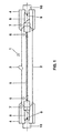
- FIG. 1 shows a double-ended, socketed halogen incandescent lamp 1 (Soffitte) for general lighting with an output of 150 W. It is for suitable for direct connection to the 230 V network and has a cylindrical Piston 2 made of quartz glass. A pump stem 3 is attached in the middle. The two ends of the piston are each closed with a pinch seal 4. The piston 2 is filled with argon, which is known per se Halogen additive is attached.
- An axially arranged filament 5 with a luminous central section is simply spiraled (or in another embodiment double coiled).
- the (primary) spiral of the simply spiraled Filament (or the secondary coil of the double-coiled Luminous body) thus forms a cylindrical body.
- the distance between two turns is about 50 ⁇ m with a wire diameter of about 190 ⁇ m.
- the luminous element 5 has an end region 6 at each end with a steep incline. There the distance between two turns is about 500 ⁇ m.
- the luminous element is connected via internal power supply lines 7
- Molybdenum foils 8 in the press seals 4 at the ends of the piston are embedded, connected.
- electrical external leads (external power supply lines) 9 are welded on, which are connected to contacts in the ceramic bases 10.
- the power supply system is shown in more detail.
- the end area 6 of the filament extends over a few turns (only one turn is shown schematically).
- the power supply 7 from Tungsten with a wire diameter of approximately 600 ⁇ m is approximately U-shaped bent and has a straight base 15. It is in a fold 12 the film hung, which by folding back an end portion 11 of the Foil is formed, the filament side of the film 8 in the form of a is arranged asymmetrically to the lamp axis arranged triangle.
- the free ends 18 are angled inwards (17) and up to extend the interior of the end portion 6 of the filament.
- the bend 17 forms an inward shortly before the end of the filament Bend 17, the free leg ends 18 each on the inside Windings of the end region 6 are applied.
- the leg ends 18 are advantageous bent slightly outwards before insertion into the filament, see above that they still exert a certain spring force when installed.
- This version is suitable for small wattages where the Luminous body is relatively small and unstable for electrical reasons.
- the first leg end 18 shaped exactly as in Figure 2 with a hook end.
- the second Leg end 19 is, however, much longer than the first. It serves as a guide. With him the hook part is directed inwards.
- the end section 13 of the film is rounded in this embodiment.
- the luminous element is 25 a high-watt lamp (500 W) so stable that the hook parts 26, the are bent back at an acute angle at an angle ⁇ of 45 ° are hooked in after the second turn.
- the curvature 27 of the legs 28 is bent more smoothly than in the first embodiment.
- This variant is preferably applicable with a relatively large diameter of the power supply.
- the folded end portion 14 has the shape of a triangle that is symmetrical is arranged to the lamp axis.
- the legs 30 are set at right angles to the base 31 and run parallel to each other.
- the hook parts 32 are angled by 90 ° and protrude opposite each other perpendicularly from the plane of the legs 30 out.
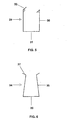
- legs 35 are inclined obliquely inwards on the base 36 stated.
- the hook parts 37 are angled at 110 ° and remain in the System level consisting of leg 35 and base 36.
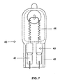
- FIG. 7 shows a halogen incandescent lamp 40 which is pinched on one side and whose two molybdenum foils 41 parallel to one another in a single pinch 42 are embedded.
- Both inner power supply lines 43 are similar to that in FIG Figure 2 described constructed and hold the ends of a U-shaped curve Filament 44.
Landscapes
- Engineering & Computer Science (AREA)
- Manufacturing & Machinery (AREA)
- Vessels And Coating Films For Discharge Lamps (AREA)
- Electric Stoves And Ranges (AREA)
Description
- Figur 1
- eine Soffittenlampe
- Figur 2
- eine vergrößerte Darstellung des Stromzuführungssystems
- Figur 3
- ein weiteres Ausführungsbeispiel des Stromzuführungssystems
- Figur 4
- ein weiteres Ausführungsbeispiel des Stromzuführungssystems
- Figur 5
- ein weiteres Ausführungsbeispiel einer Stromzuführung
- Figur 6
- ein weiteres Ausführungsbeispiel einer Stromzuführung
- Figur 7
- ein Ausführungsbeispiel einer einseitig gequetschten Halogenglühlampe
Claims (13)
- Halogenglühlampe mit einem hermetisch abgedichteten Kolben (2) aus lichtdurchlässigem Material, der eine Lampenachse definiert, mit einem gewendelten, einen Zylinder bildenden Leuchtkörper (5) mit zwei Endbereichen (6) und mit einem Stromzuführungssystem, das mit den beiden Endbereichen (6) des Leuchtkörpers verbunden ist, wobei das Stromzuführungssystem Folien (8) umfaßt wobei ein Abschnitt (11) am leuchtkörperseitigen Ende der zugehörigen Folie zurückgeklappt ist und eine Falte (12) bildet, dadurch gekennzeichnet, daß das Stromzuführungssystem Zusätliche Stromzuführungen (7) umfaßt, wobei das leuchtkörperseitige innere Ende der Stromzuführung den Endbereich (6) des Leuchtkörpers von innen her haltert, und wobei das folienseitige äußere Ende der Stromzuführung mit der Folie (8) verbunden ist und die Stromzuführung (7) U-förmig gebogen ist, indem zwei freie Schenkel (16), die in einer Ebene liegen, über eine gerade Basis (15) miteinander verbunden sind, und in der Falte (12) mechanisch gehaltert ist, wobei die Enden (18) der Schenkel (16) in den Endbereich (6) des Leuchtkörpers hineinragen und mindestens ein Hakenteil (20) an einem der Schenkelenden nach außen absteht, das zwischen zwei Windungen des Leuchtkörpers eingreift.
- Halogenglühlampe nach Anspruch 1, dadurch gekennzeichnet, daß jeder der beiden Schenkelenden (18) ein Hakenteil (20) aufweist.
- Halogenglühlampe nach Anspruch 1, dadurch gekennzeichnet, daß die Halogenglühlampe (1;40) zweiseitig oder einseitig gequetscht ist.
- Halogenglühlampe nach Anspruch 1, dadurch gekennzeichnet, daß der Durchmesser des Drahtes der Stromzuführung (7) mindestens genauso so groß, bevorzugt 10 bis 30% größer, als der Abstand zweier Windungen des Leuchtkörpers im Bereich des Eingriffs der Hakenteile ist.
- Halogenglühlampe nach Anspruch 1, dadurch gekennzeichnet, daß das Hakenteil (20) in der Ebene der Stromzuführung gebogen ist.
- Halogenglühlampe nach Anspruch 1, dadurch gekennzeichnet, daß das Hakenteil (20) über den Leuchtkörper hinaus nach außen ragt.
- Halogenglühlampe nach Anspruch 1, dadurch gekennzeichnet, daß die freien Schenkel achsparallel (Fig. 5) sind oder geradlinig nach innen, zur Achse hin, geneigt verlaufen (Figur 6) oder eine Krümmung (17;27) aufweisen, die den Abstand zwischen ihnen verringert.
- Halogenglühlampe nach Anspruch 1, dadurch gekennzeichnet, daß das Hakenteil in einem Winkel α zwischen 30° und 120°, insbesondere etwa 50° bis 60°, relativ zum Schenkelende, abgebogen ist.
- Halogenglühlampe nach Anspruch 1, dadurch gekennzeichnet, daß die Schenkelenden mindestens zwei Windungen weit in den Endbereich (6) des Leuchtkörpers eingeführt sind.
- Halogenglühlampe nach Anspruch 1, dadurch gekennzeichnet, daß der umgeklappte Abschnitt (11) der Folie an mindestens einer seiner beiden freien Ecken eine reduzierte Fläche aufweist und insbesondere dreiekkig oder abgerundet geformt ist.
- Elektrische Lampe mit einem hermetisch abgedichteten Kolben (2) aus lichtdurchlässigem Material, der eine Lampenachse definiert, einem Leuchtmittel (5) mit zwei Endbereichen (6) und einem Stromzuführungssystem, das mit den beiden Endbereichen (6) des Leuchtmittels verbunden ist, wobei das Stromzuführungssystem Folien (8) umfaßt, wobei zumindest ein Abschnitt (11) an einem Ende der Folie zurückgeklappt ist und eine Falte (12) bildet, dadurch gekennzeichnet, daß das Stromzuführungssystem zusätlich Stromzuführungen (7) umfaßt, wobei das leuchtkörperseitige innere Ende der inneren Stromzuführung den Leuchtkörper mit Hilfe von zwei Schenkeln (16), die in einer Ebene über eine gerade Basis (15) verbunden sind, haltert, und wobei das folienseitige äußere Ende der inneren Stromzuführung ebenso wie die äußere Stromzuführung (9) mit der Folie (8) verbunden ist,
und wobei mindestens eine der Stromzuführungen an der Basis (15) in dieser mindestens einen Falte (12) mechanisch gehaltert ist, und der umgeklappte Abschnitt (11) der Folie an mindestens einer seiner beiden freien Ecken eine reduzierte Fläche aufweist und insbesondere dreieckig oder abgerundet geformt ist. - Verfahren zum Herstellen einer Halogenglühlampe nach Anspruch 1, dadurch gekennzeichnet, daß die Stromzuführung (7) mit den beiden Schenkeln (16) zunächst zusammengedrückt wird und in den Endbereich (6) des Leuchtkörpers mindestens zwei Windungen weit eingeführt und dann entspannt wird, so daß beim Entspannen die Schenkel nach außen drücken und gleichmäßig von innen am Endbereich des Leuchtkörpers anliegen, während die Hakenteile (20) sich in den Zwischenraum zwischen zwei Windungen klemmend hineindrücken.
- Verfahren nach Anspruch 12, dadurch gekennzeichnet, daß der leuchtkörperseitige Endabschnitt der Folie (8) zunächst nur um mehr als 90° (bevorzugt mindestens 100°) abgewinkelt wird, so daß eine Falte (12) in der Folie entsteht und in diese die Stromzuführung (7) mit ihrer Basis (15) eingehängt wird, und anschließend der abgewinkelte Abschnitt der Folie ganz abgewinkelt wird, so daß er eine Biegung um insgesamt 180° erfährt.
Priority Applications (1)
| Application Number | Priority Date | Filing Date | Title |
|---|---|---|---|
| EP03013242A EP1355344A3 (de) | 1998-03-20 | 1999-02-26 | Elektrische Lampe |
Applications Claiming Priority (2)
| Application Number | Priority Date | Filing Date | Title |
|---|---|---|---|
| DE19812379A DE19812379A1 (de) | 1998-03-20 | 1998-03-20 | Halogenglühlampe |
| DE19812379 | 1998-03-20 |
Related Child Applications (1)
| Application Number | Title | Priority Date | Filing Date |
|---|---|---|---|
| EP03013242A Division EP1355344A3 (de) | 1998-03-20 | 1999-02-26 | Elektrische Lampe |
Publications (3)
| Publication Number | Publication Date |
|---|---|
| EP0944112A2 EP0944112A2 (de) | 1999-09-22 |
| EP0944112A3 EP0944112A3 (de) | 1999-09-29 |
| EP0944112B1 true EP0944112B1 (de) | 2003-07-23 |
Family
ID=7861750
Family Applications (2)
| Application Number | Title | Priority Date | Filing Date |
|---|---|---|---|
| EP99103807A Expired - Lifetime EP0944112B1 (de) | 1998-03-20 | 1999-02-26 | Halogenglühlampe, elektrische Lampe und Verfahren zur Herstellung einer Halogenglühlampe |
| EP03013242A Withdrawn EP1355344A3 (de) | 1998-03-20 | 1999-02-26 | Elektrische Lampe |
Family Applications After (1)
| Application Number | Title | Priority Date | Filing Date |
|---|---|---|---|
| EP03013242A Withdrawn EP1355344A3 (de) | 1998-03-20 | 1999-02-26 | Elektrische Lampe |
Country Status (6)
| Country | Link |
|---|---|
| US (1) | US6291934B1 (de) |
| EP (2) | EP0944112B1 (de) |
| JP (1) | JPH11329370A (de) |
| CN (1) | CN1296965C (de) |
| CA (1) | CA2265397A1 (de) |
| DE (2) | DE19812379A1 (de) |
Families Citing this family (11)
| Publication number | Priority date | Publication date | Assignee | Title |
|---|---|---|---|---|
| FR2795553A1 (fr) * | 1999-06-28 | 2000-12-29 | Koninkl Philips Electronics Nv | Lampe a incandescence comprenant une ampoule en verre de forme tubulaire dans laquelle est dispose axialement un filament |
| JP3085303B1 (ja) * | 1999-07-05 | 2000-09-04 | ウシオ電機株式会社 | 放電ランプ |
| EP1308988B1 (de) * | 2001-10-23 | 2016-07-13 | Koninklijke Philips N.V. | System für die Kupplung eines Filaments mit einer Stromzuführung |
| US20050093420A1 (en) * | 2003-11-05 | 2005-05-05 | Fridrich Elmer G. | Spurred light source lead wire for handling and for assembling with a filament |
| DE102004061734A1 (de) * | 2004-12-22 | 2006-07-06 | Patent-Treuhand-Gesellschaft für elektrische Glühlampen mbH | Befestigungsverfahren und danach hergestellte Lampe |
| DE112007003666A5 (de) * | 2007-11-14 | 2010-12-23 | Osram Gesellschaft mit beschränkter Haftung | Folie für Lampen und zugehöriges Stromführungssystem |
| DE202008008379U1 (de) | 2008-06-23 | 2008-09-04 | Osram Gesellschaft mit beschränkter Haftung | Folie für Lampen und zugehöriges Stromzuführungssystem und elektrische Lampe mit jeweils einer derartigen Folie |
| DE102008037319A1 (de) | 2008-08-11 | 2010-02-18 | Osram Gesellschaft mit beschränkter Haftung | Folie für Lampen und elektrische Lampe mit einer derartigen Folie sowie zugehöriges Herstellverfahren |
| DE102011089810A1 (de) | 2011-12-23 | 2013-06-27 | Evonik Industries Ag | Mischoxid enthaltend die Elemente Lithium, Nickel, Cobalt und Mangan und Verfahren zu deren Herstellung |
| US20140038117A1 (en) * | 2012-07-31 | 2014-02-06 | Bishara Tannous | Ignition device and method |
| CN104588899B (zh) * | 2014-12-01 | 2017-02-01 | 广明源光科技股份有限公司 | 一种卤素灯的自动点焊工艺及其自动点焊机 |
Family Cites Families (8)
| Publication number | Priority date | Publication date | Assignee | Title |
|---|---|---|---|---|
| GB663309A (en) * | 1948-05-01 | 1951-12-19 | British Thomson Houston Co Ltd | Improvements relating to the production of quartz-to-metal seals |
| US2786882A (en) * | 1951-01-25 | 1957-03-26 | Krefft Hermann Eduard | Lead-in seal for electrical discharge devices |
| DE1589294A1 (de) * | 1967-06-19 | 1970-06-04 | Patra Patent Treuhand | Halogengluehlampe,insbesondere fuer Kraftfahrzeugscheinwerfer |
| GB1340778A (en) * | 1971-12-02 | 1974-01-30 | Thorn Electrical Ind Ltd | Filament assejbly for incandescent lamps |
| US4208606A (en) * | 1979-01-10 | 1980-06-17 | Westinghouse Electric Corp. | Filament-support means for a tubular incandescent lamp |
| US5140217A (en) | 1990-09-07 | 1992-08-18 | North American Philips Corporation | Electric lamp having a push-in filament insert for filament mounting |
| US5241239A (en) * | 1991-12-18 | 1993-08-31 | North American Philips Corporation | Tubular electric lamp having a lamp base sleeve with an access port for securing a contact to a current-conductor |
| DE19548523A1 (de) * | 1995-12-22 | 1997-06-26 | Patent Treuhand Ges Fuer Elektrische Gluehlampen Mbh | Zweiseitig gequetschte Lampe |
-
1998
- 1998-03-20 DE DE19812379A patent/DE19812379A1/de not_active Withdrawn
-
1999
- 1999-02-26 DE DE59906318T patent/DE59906318D1/de not_active Expired - Lifetime
- 1999-02-26 EP EP99103807A patent/EP0944112B1/de not_active Expired - Lifetime
- 1999-02-26 EP EP03013242A patent/EP1355344A3/de not_active Withdrawn
- 1999-03-12 US US09/267,810 patent/US6291934B1/en not_active Expired - Fee Related
- 1999-03-17 JP JP11071816A patent/JPH11329370A/ja active Pending
- 1999-03-17 CA CA002265397A patent/CA2265397A1/en not_active Abandoned
- 1999-03-22 CN CNB991041682A patent/CN1296965C/zh not_active Expired - Fee Related
Also Published As
| Publication number | Publication date |
|---|---|
| DE59906318D1 (de) | 2003-08-28 |
| EP0944112A3 (de) | 1999-09-29 |
| EP0944112A2 (de) | 1999-09-22 |
| US6291934B1 (en) | 2001-09-18 |
| CA2265397A1 (en) | 1999-09-20 |
| CN1296965C (zh) | 2007-01-24 |
| EP1355344A3 (de) | 2009-04-01 |
| JPH11329370A (ja) | 1999-11-30 |
| CN1230011A (zh) | 1999-09-29 |
| DE19812379A1 (de) | 1999-09-23 |
| EP1355344A2 (de) | 2003-10-22 |
Similar Documents
| Publication | Publication Date | Title |
|---|---|---|
| DE3121077C2 (de) | ||
| EP0944112B1 (de) | Halogenglühlampe, elektrische Lampe und Verfahren zur Herstellung einer Halogenglühlampe | |
| DE69516345T2 (de) | Sperrbügel für Lampensockel | |
| EP0239006B1 (de) | Halogenglühlampe und Verfahren zu ihrer Herstellung | |
| WO1997040511A1 (de) | Reflektorlampe | |
| EP0446460B1 (de) | Einseitig gequetschte Halogenglühlampe | |
| EP2337061A1 (de) | Elektrische Lampe mit einem Außenkolben, einem Tellerfuß und einer Einbaulampe | |
| DE4305503A1 (de) | Einseitig gesockelte elektrische Lampe | |
| DE19856871A1 (de) | Kittlos gesockelte Lampe | |
| EP2483913B1 (de) | Hochdruckentladungslampe mit zündhilfe | |
| DE29910604U1 (de) | Reflektorlampe | |
| WO2010124904A1 (de) | Entladungslampe | |
| EP0758142A2 (de) | Halogenglühlampe | |
| DE2118061B2 (de) | Verfahren zur Herstellung von Glühlampen | |
| DE10325552A1 (de) | Elektrische Lampe mit Außenkolben und zugehöriger Trägerkörper | |
| DE69011145T2 (de) | Einseitig gequetschte Metalldampfentladungslampe. | |
| DE1953276U (de) | Gluehlampe mit einer halterungsvorrichtung fuer den gluehfaden. | |
| DE4230815A1 (de) | Hochdruckentladungslampe und Herstellungsverfahren für eine Hochdruckentladungslampe | |
| DE3406775A1 (de) | Elektrische lampe mit selbsthalternder rahmenbaugruppe und verfahren zu ihrer herstellung | |
| DE10312720A1 (de) | Dielektrische Barriere-Entladungslampe mit Quetschdichtung | |
| EP0446461B1 (de) | Einseitig gequetschte Halogen-Glühlampe | |
| DE9102566U1 (de) | Halogenglühlampe | |
| DE3886730T2 (de) | Niederdruckedelgasentladungslampe mit glühelektrode. | |
| DE202004012220U1 (de) | Einseitig verschlossene elektrische Lampe | |
| WO2011018326A1 (de) | Hochdruckentladungslampe mit zündhilfe |
Legal Events
| Date | Code | Title | Description |
|---|---|---|---|
| PUAI | Public reference made under article 153(3) epc to a published international application that has entered the european phase |
Free format text: ORIGINAL CODE: 0009012 |
|
| PUAL | Search report despatched |
Free format text: ORIGINAL CODE: 0009013 |
|
| AK | Designated contracting states |
Kind code of ref document: A2 Designated state(s): BE DE FR GB IT NL |
|
| AX | Request for extension of the european patent |
Free format text: AL;LT;LV;MK;RO;SI |
|
| AK | Designated contracting states |
Kind code of ref document: A3 Designated state(s): AT BE CH CY DE DK ES FI FR GB GR IE IT LI LU MC NL PT SE |
|
| AX | Request for extension of the european patent |
Free format text: AL;LT;LV;MK;RO;SI |
|
| 17P | Request for examination filed |
Effective date: 19991019 |
|
| AKX | Designation fees paid |
Free format text: BE DE FR GB IT NL |
|
| RTI1 | Title (correction) |
Free format text: HALOGEN INCANDESCENT LAMP, ELECTRIC LAMP AND METHOD FOR MANUFACTURING A HALOGEN INCANDESCENT LAMP |
|
| RTI1 | Title (correction) |
Free format text: HALOGEN INCANDESCENT LAMP, ELECTRIC LAMP AND METHOD FOR MANUFACTURING A HALOGEN INCANDESCENT LAMP |
|
| RTI1 | Title (correction) |
Free format text: HALOGEN INCANDESCENT LAMP, ELECTRIC LAMP AND METHOD FOR MANUFACTURING A HALOGEN INCANDESCENT LAMP |
|
| GRAH | Despatch of communication of intention to grant a patent |
Free format text: ORIGINAL CODE: EPIDOS IGRA |
|
| GRAH | Despatch of communication of intention to grant a patent |
Free format text: ORIGINAL CODE: EPIDOS IGRA |
|
| GRAA | (expected) grant |
Free format text: ORIGINAL CODE: 0009210 |
|
| AK | Designated contracting states |
Designated state(s): BE DE FR GB IT NL |
|
| REG | Reference to a national code |
Ref country code: GB Ref legal event code: FG4D Free format text: NOT ENGLISH |
|
| REF | Corresponds to: |
Ref document number: 59906318 Country of ref document: DE Date of ref document: 20030828 Kind code of ref document: P |
|
| GBT | Gb: translation of ep patent filed (gb section 77(6)(a)/1977) |
Effective date: 20031103 |
|
| ET | Fr: translation filed | ||
| PLBE | No opposition filed within time limit |
Free format text: ORIGINAL CODE: 0009261 |
|
| STAA | Information on the status of an ep patent application or granted ep patent |
Free format text: STATUS: NO OPPOSITION FILED WITHIN TIME LIMIT |
|
| 26N | No opposition filed |
Effective date: 20040426 |
|
| PGFP | Annual fee paid to national office [announced via postgrant information from national office to epo] |
Ref country code: BE Payment date: 20060214 Year of fee payment: 8 |
|
| PGFP | Annual fee paid to national office [announced via postgrant information from national office to epo] |
Ref country code: NL Payment date: 20060215 Year of fee payment: 8 |
|
| PGFP | Annual fee paid to national office [announced via postgrant information from national office to epo] |
Ref country code: IT Payment date: 20060228 Year of fee payment: 8 |
|
| GBPC | Gb: european patent ceased through non-payment of renewal fee |
Effective date: 20070226 |
|
| NLV4 | Nl: lapsed or anulled due to non-payment of the annual fee |
Effective date: 20070901 |
|
| BERE | Be: lapsed |
Owner name: *PATENT-TREUHAND-G.- FUR ELEKTRISCHE GLUHLAMPEN M. Effective date: 20070228 |
|
| PG25 | Lapsed in a contracting state [announced via postgrant information from national office to epo] |
Ref country code: BE Free format text: LAPSE BECAUSE OF NON-PAYMENT OF DUE FEES Effective date: 20070228 |
|
| PG25 | Lapsed in a contracting state [announced via postgrant information from national office to epo] |
Ref country code: NL Free format text: LAPSE BECAUSE OF NON-PAYMENT OF DUE FEES Effective date: 20070901 |
|
| PG25 | Lapsed in a contracting state [announced via postgrant information from national office to epo] |
Ref country code: GB Free format text: LAPSE BECAUSE OF NON-PAYMENT OF DUE FEES Effective date: 20070226 |
|
| PGFP | Annual fee paid to national office [announced via postgrant information from national office to epo] |
Ref country code: GB Payment date: 20060209 Year of fee payment: 8 |
|
| PG25 | Lapsed in a contracting state [announced via postgrant information from national office to epo] |
Ref country code: IT Free format text: LAPSE BECAUSE OF NON-PAYMENT OF DUE FEES Effective date: 20070226 |
|
| REG | Reference to a national code |
Ref country code: DE Ref legal event code: R081 Ref document number: 59906318 Country of ref document: DE Owner name: OSRAM GMBH, DE Free format text: FORMER OWNER: OSRAM GESELLSCHAFT MIT BESCHRAENKTER HAFTUNG, 81543 MUENCHEN, DE Effective date: 20111130 |
|
| PGFP | Annual fee paid to national office [announced via postgrant information from national office to epo] |
Ref country code: FR Payment date: 20120227 Year of fee payment: 14 |
|
| PGFP | Annual fee paid to national office [announced via postgrant information from national office to epo] |
Ref country code: DE Payment date: 20120420 Year of fee payment: 14 |
|
| REG | Reference to a national code |
Ref country code: DE Ref legal event code: R081 Ref document number: 59906318 Country of ref document: DE Owner name: OSRAM GMBH, DE Free format text: FORMER OWNER: OSRAM AG, 81543 MUENCHEN, DE Effective date: 20130205 |
|
| REG | Reference to a national code |
Ref country code: DE Ref legal event code: R081 Ref document number: 59906318 Country of ref document: DE Owner name: OSRAM GMBH, DE Free format text: FORMER OWNER: OSRAM GMBH, 81543 MUENCHEN, DE Effective date: 20130822 |
|
| REG | Reference to a national code |
Ref country code: FR Ref legal event code: ST Effective date: 20131031 |
|
| REG | Reference to a national code |
Ref country code: DE Ref legal event code: R119 Ref document number: 59906318 Country of ref document: DE Effective date: 20130903 |
|
| PG25 | Lapsed in a contracting state [announced via postgrant information from national office to epo] |
Ref country code: FR Free format text: LAPSE BECAUSE OF NON-PAYMENT OF DUE FEES Effective date: 20130228 Ref country code: DE Free format text: LAPSE BECAUSE OF NON-PAYMENT OF DUE FEES Effective date: 20130903 |