EP0943871B1 - Dunstabzugsvorichtung für Küchen - Google Patents
Dunstabzugsvorichtung für Küchen Download PDFInfo
- Publication number
- EP0943871B1 EP0943871B1 EP99104294A EP99104294A EP0943871B1 EP 0943871 B1 EP0943871 B1 EP 0943871B1 EP 99104294 A EP99104294 A EP 99104294A EP 99104294 A EP99104294 A EP 99104294A EP 0943871 B1 EP0943871 B1 EP 0943871B1
- Authority
- EP
- European Patent Office
- Prior art keywords
- fume extractor
- hood
- cassette housing
- extractor hood
- air
- Prior art date
- Legal status (The legal status is an assumption and is not a legal conclusion. Google has not performed a legal analysis and makes no representation as to the accuracy of the status listed.)
- Expired - Lifetime
Links
Images
Classifications
-
- F—MECHANICAL ENGINEERING; LIGHTING; HEATING; WEAPONS; BLASTING
- F24—HEATING; RANGES; VENTILATING
- F24C—DOMESTIC STOVES OR RANGES ; DETAILS OF DOMESTIC STOVES OR RANGES, OF GENERAL APPLICATION
- F24C15/00—Details
- F24C15/20—Removing cooking fumes
-
- F—MECHANICAL ENGINEERING; LIGHTING; HEATING; WEAPONS; BLASTING
- F24—HEATING; RANGES; VENTILATING
- F24C—DOMESTIC STOVES OR RANGES ; DETAILS OF DOMESTIC STOVES OR RANGES, OF GENERAL APPLICATION
- F24C15/00—Details
- F24C15/20—Removing cooking fumes
- F24C15/2035—Arrangement or mounting of filters
Definitions
- the invention relates to an extractor device for kitchens according to the preamble of claim 1.
- Such an extractor device is known from DE-B-23 63 820. Is with her an odor filter cartridge inside the housing of an extractor hood, in which there is also a grease filter and a blower.
- the filter material of the Odor filter can be activated carbon or another material that is affected by adhesion, Adsorption, absorption or other chemical ways odors from the Filters out the airflow generated by the fan and first by the Grease filter and then flows through the odor filter.
- the blower can Flow path between the fat filter and the odor filter may be arranged, such as this this document and also the DE utility model G 91 05 430.3 show. According to DE-A-27 14 286 and DE utility model 1 987 333 it is also possible to place the blower downstream of the odor filter. It is also from the DE utility model GM 78 02 041 known, several, for example, in an extractor hood to use two blowers.
- the object of the invention is to achieve an extractor device for To create kitchens that can be used with or without an odor filter unit and which is very small in both situations, especially one has a small overall height.
- the construction should be very simple and only a few Need components.
- the invention provides the option of optionally selecting the extractor device to use with or without odor filter unit.
- the extractor hood has a very low height.
- the construction is very simple and requires only a few parts.
- the extractor hood used is preferably designed as a base unit, which is under an upper cabinet can be hung, which is attached to a wall.
- the Undercounter cooker hood optionally either directly under an upper cabinet arranged and attached to it, or a small distance below the Upper cabinet are hung so that the odor filter unit in the space can be used and placed on the extractor hood. With this onset and putting on takes place automatically a flow connection between the extractor hood and the odor filter unit.
- the odor filter unit prevents exhaust air from escaping into the external environment, so that the exhaust outlet of the extractor hood has no additional locking means needed to switch from exhaust air mode to recirculation mode.
- Exhaust air operation without an odor filter makes the exhaust air opening of the extractor hood direct connected to an exhaust air duct, which from the kitchen from the house into the Free can lead.
- the exhaust air of the odor filter returned to the kitchen which the fan sucks the air into the extractor hood.
- you can the odor filter unit should also be designed so that its exhaust air does not enter the kitchen, also gets into a drain line, which leads from the house into the open leads.
- the kitchen extractor hood shown in the drawings includes one Undermount extractor hood 2 and an odor filter cassette 4.
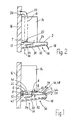
- the extractor hood 2 can either be long screws as shown in FIG. 1 6 and spacer sleeves 8 leaving a space 10 or according to 2 avoiding such a space 10 directly on the underside 12 of an upper cabinet.
- the upper cabinet 14 is in one, for example Kitchen attached to the kitchen wall 16 at a distance from the floor.
- a vertical passage 18 is formed for an exhaust duct 20.
- the extractor hood 2 When using the extractor hood 2 without the odor filter cartridge 4 according to Fig. 2 can the lower end of the exhaust duct 20 into an air outlet port 22 are inserted, which in the rear half of a closed ceiling 24 of the Extractor hood 2 is formed.
- the upper end of the exhaust line 20 is at one Wall opening 26 connected.
- the floor 30 of the extractor hood 2 is as a grid, perforated plate, perforated expanded metal or in otherwise permeable to air.
- On the floor 30 is a single layer or multilayer grease filter 32.
- a fan 34 arranged in the extractor hood 2 sucks air 36 from the kitchen through the grease filter 32 and drives it through the exhaust line 20 and the wall opening 26 from the house.
- the same extractor hood 2 for Recirculation mode can be used, in which the air sucked in by the fan 34 36 is passed back through the odor filter cassette 4 into the kitchen, accordingly Arrows 39 in Fig.1.
- the space 10 between the extractor hood 2 and the Bottom 12 of the upper cabinet 14 is so narrow that the odor filter cartridge 4 by inserted into the space 10 at the front and placed on the extractor hood 2 can be, but no significant space between the odor filter cassette 4 and the underside 12 of the upper cabinet 14 remains.
- Air inlet port 40 formed in a bottom 42 of the odor filter cartridge is placed on the air outlet connection opening of the extractor hood 2 and with this automatically connected.
- This has the advantage that no additional connection elements are required, and that the air outlet port 22 automatically closed by the odor filter cassette 4 against the outside environment becomes.
- the exhaust air from the extractor hood 2 now flows from its air outlet connection opening 22 into the odor filter cassette via the air inlet connection opening 40 4 and in this through odor filter material 44, for example activated carbon or another material that filters odors out of the air through absorption, Adsorption or other chemical means.
- That of fat in the fat filter 32 and Air 39 cleaned of odors in the odor filter material 44 passes through an air outlet 46 from the odor filter cassette 4 into the external device environment, i.e. in the Kitchen back.
- the air outlet 46 is through a plurality of openings in one sloping forward downward, towards the floor 42 sloping front ceiling section 48 of a housing of the odor filter cassette 4 is formed.
- the bottom 30 of the extractor hood 2 is inclined over its entire width formed at the top and rising towards the hood ceiling 24.
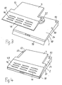
- the Extractor hood across its entire width a wedge shape that becomes flatter towards the front, and also the odor filter cassette 4 has at least in its front third Wedge shape flattening towards the front.
- the air outlet connection opening 22 is the extractor hood 2 formed by a pipe socket installed in its ceiling 24, in or on which either the exhaust line 20 or the air inlet connection opening 40 can be set can.
- the latter can also have the shape of a pipe socket, which in or on the pipe socket of the air outlet connection opening 22 fits.
- Figures 3 and 4 show in the ceiling 24 of the extractor hood 2 holes 50 formed for the screws 6 of Fig.1 or screws 7 of Fig.2 for hanging the extractor hood 2 on the Upper cabinet 14.
- the odor filter cassette 4 in their ceiling 52 have an air outlet connection opening which is circular Has shape corresponding to the nozzle 22 and connectable to the exhaust duct 20 is.
- you have the advantage that the extractor hood 2 and the odor filter cassette 4 are very flat units, which are optionally individually or can be used in combination. Each of these two units 2 and 4 has essentially flat, mating surfaces, which also are adapted to each other with respect to their peripheral edges.
Landscapes
- Engineering & Computer Science (AREA)
- Chemical & Material Sciences (AREA)
- Combustion & Propulsion (AREA)
- Mechanical Engineering (AREA)
- General Engineering & Computer Science (AREA)
- Ventilation (AREA)
- Filtering Of Dispersed Particles In Gases (AREA)
- Prevention Of Fouling (AREA)
Description
- Fig.1
- schematisch eine Seitenansicht einer Dunstabzugsvorrichtung nach der Erfindung mit einem Fettfilter und einem Geruchsfilter für Umluftbetrieb,
- Fig.2
- die Dunstabzugsvorrichtung von Fig.1 bei Abluftbetrieb ohne Geruchsfilter,
- Fig.3
- perspektivisch die Dunstabzugsvorrichtung von Fig.1 in Explosionsdarstellung,
- Fig.4
- perspektivisch die Dunstabzugsvorrichtung von Fig.1.
Claims (8)
- Dunstabzugsvorrichtung für Küchen, mit einem Fettfilter (32) und mindestens einem Gebläse (34) in einer Dunstabzugshaube (2), welche in einer Haubendecke (24) eine Luftauslaß-Anschlußöffnung (22) aufweist, die an eine Abluftleitung (20) anschließbar ist, und mit einem Geruchsfilter (4), welcher dem Fettfilter in Strömungsrichtung eines von dem Gebläse erzeugten Luftstromes nachgeordnet ist, dadurch gekennzeichnet, daß der Geruchsfilter (4) ein Kassettengehäuse mit Geruchsfiltermaterial (44) zwischen einer Lufteinlaß-Anschlußöffnung (40) im Gehäuseboden (42)und mit einem Luftauslaß auf einer anderen Gehäuseseite aufweist, daß das Kassettengehäuse auf die Dunstabzugshaube (2) aufsetzbar ist, wobei durch dieses Aufsetzen die Lufteinlaß-Anschlußöffnung (40) des Kassettengehäuses mit der Luftauslaß-Anschlußöffnung (22) der Dunstabzugshaube (2) automatisch verbunden wird.
- Dunstabzugsvorrichtung nach Anspruch 1, dadurch gekennzeichnet, daß der Luftauslaß (46) des Kassettengehäuses eine Vielzahl von Öffnungen aufweist, zur Abgabe des Luftstromes (39) in die externe Umgebung, aus welcher das Gebläse (34) die Luft des Luftstromes in die Dunstabzugshaube (2) saugt.
- Dunstabzugsvorrichtung nach einem der vorhergehenden Ansprüche, dadurch gekennzeichnet, daß die Dunstabzugshaube (2) als Unterbaueinheit ausgebildet ist, welche unter einem Oberschrank (14) plazierbar und befestigbar ist.
- Dunstabzugsvorrichtung nach Anspruch 3, dadurch gekennzeichnet, daß die Dunstabzugshaube (2) Aufhängemittel (6,7,8,50) zur wahlweisen Aufhängung direkt unter den Oberschrank (14) oder mit solchem Abstand (10) unter den Oberschrank (14) aufweist, daß das Kassettengehäuse des Geruchsfilters (4) in einen Zwischenraum zwischen Oberschrank (14) und Dunstabzugshaube (2) einführbar und auf die Dunstabzugshaube (2) setzbar ist.
- Dunstabzugsvorrichtung nach einem der vorhergehenden Ansprüche, dadurch gekennzeichnet, daß der Luftauslaß (46) des Geruchsfilter-Kassettengehäuses in einem schräg nach vorne unten, in Richtung zu einem Boden (42) des Kassettengehäuses abfallenden vorderen Abschnitt (48) einer Kassettengehäuse-Decke (52) gebildet ist.
- Dunstabzugsvorrichtung nach einem der vorhergehenden Ansprüche, dadurch gekennzeichnet, daß die Luftauslaß-Anschlußöffnung (22) der Dunstabzugshaube (2) in einer hinteren Haubenhälfte vorgesehen ist, und daß die Lufteinlaß-Anschlußöffnung (40) des Geruchsfilter-Kassettengehäuses in der hinteren Hälfte dieses Kassettengehäuses vorgesehen ist.
- Dunstabzugsvorrichtung nach einem der vorgehenden Ansprüche, dadurch gekennzeichnet, daß der Boden(30) der Dunstabzugshaube (2) schräg nach vorne oben in Richtung zur Haubendecke (24) hin ansteigend ausgebildet ist.
- Dunstabzugsvorrichtung nach einem der vorhergehenden Ansprüche, dadurch gekennzeichnet, daß die Decke (24) der Dunstabzugshaube (2) und der Boden (42) des Geruchsfilter-Kassettengehäuses im wesentlichen flach ausgebildet sind.
Applications Claiming Priority (2)
| Application Number | Priority Date | Filing Date | Title |
|---|---|---|---|
| DE19809223A DE19809223A1 (de) | 1998-03-04 | 1998-03-04 | Dunstabzugsvorrichtung für Küchen |
| DE19809223 | 1998-03-04 |
Publications (3)
| Publication Number | Publication Date |
|---|---|
| EP0943871A2 EP0943871A2 (de) | 1999-09-22 |
| EP0943871A3 EP0943871A3 (de) | 2000-11-15 |
| EP0943871B1 true EP0943871B1 (de) | 2004-02-18 |
Family
ID=7859678
Family Applications (1)
| Application Number | Title | Priority Date | Filing Date |
|---|---|---|---|
| EP99104294A Expired - Lifetime EP0943871B1 (de) | 1998-03-04 | 1999-03-03 | Dunstabzugsvorichtung für Küchen |
Country Status (3)
| Country | Link |
|---|---|
| EP (1) | EP0943871B1 (de) |
| DE (2) | DE19809223A1 (de) |
| ES (1) | ES2217632T3 (de) |
Families Citing this family (3)
| Publication number | Priority date | Publication date | Assignee | Title |
|---|---|---|---|---|
| FR2812933B1 (fr) * | 2000-08-09 | 2002-11-15 | Aldes Aeraulique | Hotte de cuisine motorisee |
| DE10146203A1 (de) * | 2001-09-19 | 2003-04-10 | Thorsten Fuener | Verfahren und Vorrichtung zum Abzug von Küchendünsten |
| EP1310741A3 (de) * | 2001-11-08 | 2003-11-26 | bulthaup GmbH & Co. KG | Dunsthaube |
Family Cites Families (2)
| Publication number | Priority date | Publication date | Assignee | Title |
|---|---|---|---|---|
| DE3514712A1 (de) * | 1985-04-24 | 1986-10-30 | Buderus Ag, 6330 Wetzlar | Dunstabzugshaube |
| JP2555491B2 (ja) * | 1990-08-09 | 1996-11-20 | 日本電装株式会社 | エアクリーナ |
-
1998
- 1998-03-04 DE DE19809223A patent/DE19809223A1/de not_active Withdrawn
-
1999
- 1999-03-03 DE DE59908543T patent/DE59908543D1/de not_active Expired - Fee Related
- 1999-03-03 ES ES99104294T patent/ES2217632T3/es not_active Expired - Lifetime
- 1999-03-03 EP EP99104294A patent/EP0943871B1/de not_active Expired - Lifetime
Also Published As
| Publication number | Publication date |
|---|---|
| ES2217632T3 (es) | 2004-11-01 |
| DE19809223A1 (de) | 1999-09-09 |
| EP0943871A2 (de) | 1999-09-22 |
| DE59908543D1 (de) | 2004-03-25 |
| EP0943871A3 (de) | 2000-11-15 |
Similar Documents
| Publication | Publication Date | Title |
|---|---|---|
| DE102008033792B4 (de) | Umluftmodul und Dunstabzugsvorrichtung | |
| EP3475622B1 (de) | Muldenlüfter mit einem einsatz | |
| DE1454310A1 (de) | Kochherd | |
| EP1134501A1 (de) | Dunstabzugshaube | |
| DE102009028808A1 (de) | Innenrahmen für Dunstabzugshaube und Dunstabzugshaube | |
| EP3710755B1 (de) | Dunstabzugsvorrichtung für ein kochfeld und küchenmöbel mit dunstabzugsvorrichtung | |
| DE102012207852A1 (de) | Zwischenelement für Dunstabzugshaube, insbesondere Esse, und Dunstabzugshaube | |
| EP0943871B1 (de) | Dunstabzugsvorichtung für Küchen | |
| EP2210048A2 (de) | Dunstabzugsvorrichtung | |
| EP2829808B1 (de) | Dunstabzugshaube | |
| DE20122340U1 (de) | Dunstabzugshaube | |
| EP0940634B1 (de) | Dunstabzugshauben für Kochstellen | |
| EP3722678A1 (de) | Kombinationsgerät mit kochfeld und dunstabzugsvorrichtung und küchenvorrichtung | |
| EP3869106A1 (de) | Kochfeld mit kochstelle und absaugvorrichtung für kochdünste | |
| DE4142440C2 (de) | Dunstabzugsvorrichtung | |
| EP0982548B1 (de) | Dunstabzugs-Profilsystem | |
| DE2231845C3 (de) | Dunstabzugshaube | |
| EP1094278A2 (de) | Dunstabzugsvorrichtung | |
| DE102018130963A1 (de) | Dunstabzugseinrichtung für eine Schrank- oder Küchenzeile | |
| DE102004043069A1 (de) | Dunstabzugshaube | |
| DE102008041160A1 (de) | Dunstabzugsvorrichtung | |
| DE9416271U1 (de) | Dunstabzugsvorrichtung | |
| DE2323229B2 (de) | Überwachungseinrichtung für die Filteranordnung in Dunstabzugshauben u.dgl | |
| DE3545421A1 (de) | In kuechenoberschrank integrierte dunstabzugshaube | |
| EP3299727A1 (de) | Abdeckvorrichtung für einen muldenlüfter und muldenlüftereinlasseinheit mit einer abdeckvorrichtung |
Legal Events
| Date | Code | Title | Description |
|---|---|---|---|
| PUAI | Public reference made under article 153(3) epc to a published international application that has entered the european phase |
Free format text: ORIGINAL CODE: 0009012 |
|
| AK | Designated contracting states |
Kind code of ref document: A2 Designated state(s): DE ES FR GB IT SE |
|
| AX | Request for extension of the european patent |
Free format text: AL;LT;LV;MK;RO;SI |
|
| PUAL | Search report despatched |
Free format text: ORIGINAL CODE: 0009013 |
|
| AK | Designated contracting states |
Kind code of ref document: A3 Designated state(s): AT BE CH CY DE DK ES FI FR GB GR IE IT LI LU MC NL PT SE |
|
| AX | Request for extension of the european patent |
Free format text: AL;LT;LV;MK;RO;SI |
|
| 17P | Request for examination filed |
Effective date: 20001214 |
|
| AKX | Designation fees paid |
Free format text: DE ES FR GB IT SE |
|
| 17Q | First examination report despatched |
Effective date: 20021113 |
|
| GRAP | Despatch of communication of intention to grant a patent |
Free format text: ORIGINAL CODE: EPIDOSNIGR1 |
|
| GRAS | Grant fee paid |
Free format text: ORIGINAL CODE: EPIDOSNIGR3 |
|
| GRAA | (expected) grant |
Free format text: ORIGINAL CODE: 0009210 |
|
| RAP1 | Party data changed (applicant data changed or rights of an application transferred) |
Owner name: BSH BOSCH UND SIEMENS HAUSGERAETE GMBH |
|
| AK | Designated contracting states |
Kind code of ref document: B1 Designated state(s): DE ES FR GB IT SE |
|
| REG | Reference to a national code |
Ref country code: GB Ref legal event code: FG4D Free format text: NOT ENGLISH |
|
| GBT | Gb: translation of ep patent filed (gb section 77(6)(a)/1977) |
Effective date: 20040218 |
|
| REF | Corresponds to: |
Ref document number: 59908543 Country of ref document: DE Date of ref document: 20040325 Kind code of ref document: P |
|
| REG | Reference to a national code |
Ref country code: SE Ref legal event code: TRGR |
|
| ET | Fr: translation filed | ||
| REG | Reference to a national code |
Ref country code: ES Ref legal event code: FG2A Ref document number: 2217632 Country of ref document: ES Kind code of ref document: T3 |
|
| PLBE | No opposition filed within time limit |
Free format text: ORIGINAL CODE: 0009261 |
|
| STAA | Information on the status of an ep patent application or granted ep patent |
Free format text: STATUS: NO OPPOSITION FILED WITHIN TIME LIMIT |
|
| 26N | No opposition filed |
Effective date: 20041119 |
|
| PGFP | Annual fee paid to national office [announced via postgrant information from national office to epo] |
Ref country code: GB Payment date: 20070323 Year of fee payment: 9 Ref country code: ES Payment date: 20070323 Year of fee payment: 9 |
|
| PGFP | Annual fee paid to national office [announced via postgrant information from national office to epo] |
Ref country code: SE Payment date: 20070326 Year of fee payment: 9 |
|
| PGFP | Annual fee paid to national office [announced via postgrant information from national office to epo] |
Ref country code: DE Payment date: 20070331 Year of fee payment: 9 |
|
| PGFP | Annual fee paid to national office [announced via postgrant information from national office to epo] |
Ref country code: IT Payment date: 20070605 Year of fee payment: 9 |
|
| PGFP | Annual fee paid to national office [announced via postgrant information from national office to epo] |
Ref country code: FR Payment date: 20070321 Year of fee payment: 9 |
|
| EUG | Se: european patent has lapsed | ||
| GBPC | Gb: european patent ceased through non-payment of renewal fee |
Effective date: 20080303 |
|
| REG | Reference to a national code |
Ref country code: FR Ref legal event code: ST Effective date: 20081125 |
|
| PG25 | Lapsed in a contracting state [announced via postgrant information from national office to epo] |
Ref country code: SE Free format text: LAPSE BECAUSE OF NON-PAYMENT OF DUE FEES Effective date: 20080304 Ref country code: DE Free format text: LAPSE BECAUSE OF NON-PAYMENT OF DUE FEES Effective date: 20081001 |
|
| PG25 | Lapsed in a contracting state [announced via postgrant information from national office to epo] |
Ref country code: FR Free format text: LAPSE BECAUSE OF NON-PAYMENT OF DUE FEES Effective date: 20080331 |
|
| REG | Reference to a national code |
Ref country code: ES Ref legal event code: FD2A Effective date: 20080304 |
|
| PG25 | Lapsed in a contracting state [announced via postgrant information from national office to epo] |
Ref country code: GB Free format text: LAPSE BECAUSE OF NON-PAYMENT OF DUE FEES Effective date: 20080303 |
|
| PG25 | Lapsed in a contracting state [announced via postgrant information from national office to epo] |
Ref country code: ES Free format text: LAPSE BECAUSE OF NON-PAYMENT OF DUE FEES Effective date: 20080304 |
|
| PG25 | Lapsed in a contracting state [announced via postgrant information from national office to epo] |
Ref country code: IT Free format text: LAPSE BECAUSE OF NON-PAYMENT OF DUE FEES Effective date: 20080303 |