EP0943754B1 - Concrete form member - Google Patents
Concrete form member Download PDFInfo
- Publication number
- EP0943754B1 EP0943754B1 EP99103687A EP99103687A EP0943754B1 EP 0943754 B1 EP0943754 B1 EP 0943754B1 EP 99103687 A EP99103687 A EP 99103687A EP 99103687 A EP99103687 A EP 99103687A EP 0943754 B1 EP0943754 B1 EP 0943754B1
- Authority
- EP
- European Patent Office
- Prior art keywords
- form member
- plate
- side plate
- pair
- portions
- Prior art date
- Legal status (The legal status is an assumption and is not a legal conclusion. Google has not performed a legal analysis and makes no representation as to the accuracy of the status listed.)
- Expired - Lifetime
Links
Images


Classifications
-
- E—FIXED CONSTRUCTIONS
- E04—BUILDING
- E04G—SCAFFOLDING; FORMS; SHUTTERING; BUILDING IMPLEMENTS OR AIDS, OR THEIR USE; HANDLING BUILDING MATERIALS ON THE SITE; REPAIRING, BREAKING-UP OR OTHER WORK ON EXISTING BUILDINGS
- E04G9/00—Forming or shuttering elements for general use
- E04G9/02—Forming boards or similar elements
- E04G9/05—Forming boards or similar elements the form surface being of plastics
-
- E—FIXED CONSTRUCTIONS
- E04—BUILDING
- E04G—SCAFFOLDING; FORMS; SHUTTERING; BUILDING IMPLEMENTS OR AIDS, OR THEIR USE; HANDLING BUILDING MATERIALS ON THE SITE; REPAIRING, BREAKING-UP OR OTHER WORK ON EXISTING BUILDINGS
- E04G9/00—Forming or shuttering elements for general use
- E04G9/02—Forming boards or similar elements
- E04G2009/028—Forming boards or similar elements with reinforcing ribs on the underside
Definitions
- the present invention relates to a concrete form member for assembling a concrete form employed for placing concrete or forming a concrete secondary product in construction work or engineering works, for example.
- a wooden form member prepared by nailing crossbars to a plywood board or a metal form member prepared by fixing metal ribs to an iron plate or an aluminum plate is known as this type of concrete form member.
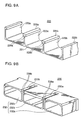
- Fig. 11A shows a form member 70 prepared by fixing a flat plate 71 of plywood, for example, to a plurality of reinforcing crossbars 72 with nails 73. In order to assemble a concrete form with such form members 70, nails 73 are driven into adjacent reinforcing crossbars 72 the form members 70 for connecting and fixing the same to each other.
- Fig. 11B shows an exemplary concrete form having a cross-shaped concrete forming part 74 assembled in the aforementioned manner.
- the flat plate 71 may be formed by a plastic plate, in place of the plywood board.
- the conventional form member space holder is mainly formed by a separator 121, attachments 122 and clamp members 123.
- the separator 121 is formed by a bar provided with a pair of male screws 121a on both ends thereof, as shown in Fig. 13A.
- Each male screw 121a is fitted with a female screw 122c provided on an end of each attachment 122 shown in Fig. 13B.
- the attachment 122 is provided on another end with a male screw 122d, which is substantially coaxial with the female screw 122c, passing through a separator mounting hole 76 provided in each form member 70 so that an end of a substantially truncated-conical presser 122a of resin engaging with the outer periphery of an attachment body part 122b is in contact with the concrete placing surface of the form member 70.
- a female screw 123a provided on an end of each clamp member 123 is fitted with the male screw 122d of the attachment 122, thereby clamping/fixing the attachment 122 to the form member 70.
- a male screw 123b is provided on another end of the clamp member 123, so that a support member 124 and a nut 125 mounted on this male screw 123b fix thin cylindrical form support members 126 of a metal to bridge a plurality of transversely arranged form members 70.
- Fig. 14A shows a form member 80 prepared by bonding/fixing side plates 82 and reinforcing plates 83 to a metal flat plate 81.
- Fig. 14B shows an exemplary concrete form having a cross-shaped concrete forming part 84 assembled by a plurality of such metal form members 80.
- metal auxiliary members 85 are employed on corners of the cross-shaped concrete forming part 84, in addition to the form members 80.
- Japanese Utility Model Laying-Open No. 62-54149 (1987) discloses a conventional form member of synthetic resin.
- reinforcing projections are integrally provided on four points on the rear surface of a plate member of plastic having a square front surface. These projections have receiving holes for connectors, while receiving holes for separators are formed in prescribed portions of the plate member.
- the wooden form member is lightweight and has a degree of freedom in execution.
- the wooden form member has such disadvantages that the same can be reused only three or four times since the plywood board absorbing strong alkaline moisture starts to come off from an end portion when used several times, requires skill for assembling/execution, is unsuitable for global environmental protection due to consumption of lauan as raw material and industrial wastes resulting after use, and is not applicable to high-grade concrete having a low slump and high strength due to limitation of employment of a vibrator resulting from low strength.
- the hygroscopic plywood board absorbs moisture from a surface of placed concrete, which is in contact with the plywood board, and an ideal water-cement ratio of the concrete is lost in this portion, to result in rough finishing of the outer surface of the concrete.
- the concrete may be erroneously regarded as defectively hardened. Therefore, prescribed coating is applied to the surface of the plywood board for reducing its hygroscopicity.
- the cost for such a coated plywood board is unpreferably increased.
- the metal form member has high strength, the degree of freedom in working is so small that the executable range is limited and the form member is hardly applicable to general construction work. Further, the heavy metal form member must inevitably be reduced in size, leading to inferior execution efficiency. Further, the metal form member is generally rusted or unusably deformed if insufficiently managed, and extremely hard to repair in such a state.
- an improved concrete form member 1 proposed in the aforementioned literature has a main plate portion 3 formed by such a long flat plate that the length between both longitudinal ends 3B is set about 10 times that between both cross-directional ends 3A, with flat front and rear surfaces 3C and 3D.
- a pair of side plate portions 4 are formed by long strip-shaped bodies pelpendicularly extending from the cross-sectional ends 3A of the main plate portion 3 toward the rear surface 3D to face each other, and surfaces 4A thereof are flatly formed.
- a pair of rear plate portions 5 are formed by long strip-shaped bodies perpendicularly extending inward from both cross-directional forward ends 4B of the side plate portions 4 to face the rear surface 3D of the main plate portion 3. Surfaces 5A of the rear plate portions 5 are flatly formed while forward ends thereof inwardly project to form reinforcing thick portions 5B.
- a plurality of mounting holes 6 are formed along the cross-directional center of the main plate portion 3 of the form member at prescribed intervals in the longitudinal direction. Further, a plurality of mounting holes 7 are formed in each of the pair of side plate portions 4 in correspondence to the positions of the mounting holes 6 of the main plate portion 3. Each mounting hole 7 is arranged on a position at a prescribed distance L from the front surface 3C of the main plate portion 3 along the cross direction. In addition, a plurality of mounting holes 8 are formed in each of the pair of rear plate portions 5 in correspondence to the positions of the mounting holes 6 of the main plate portion 3. Each mounting hole 8 is formed on a position at a distance L, identical to the distance L between the center of each mounting hole 7 and the front surface 3C of the main plate portion 3, from the surface 4A of each side plate portion 4 along the cross direction.
- each of end plate bodies 9 engaging with both longitudinal ends of a form member body 2 is formed by a flat horizontal end plate portion 10 shielding each longitudinal end of the form member body 2 and a pair of vertical end plate portions 11 and 12 perpendicularly extending from front and rear ends of the horizontal end plate portion 10, and has a substantially U-shaped section.
- the horizontal end plate portion 10 is formed to engage with a space, having a rectangular plane shape, enclosed with the main plate portion 3, the pair of side plate portions 4 and the pair of rear plate portions 5.
- the front end surface of the front vertical end plate portion 11 is in contact with and fixed to the rear surface 3D of the main plate portion 3, while the rear vertical end plate portion 12 is formed to face the vertical end plate portion 11 and engage with the pair of rear plate portions 5. All surfaces 10A, 11A and 12A of the horizontal end plate portion 10 and the pair of vertical end plate portions 11 and 12 are flatly formed.
- the horizontal end plate portion 10 is provided on its longitudinal center with a mounting hole 13, which is arranged on a portion at a distance, substantially identical to the distance L between the center of each mounting hole 7 and the surface 3C of the main plate portion 3, from the surface 3C of the main plate portion 3 along the cross direction of the horizontal end plate portion 10, as shown in Fig. 18. Further, a mounting hole 14 is formed on the longitudinal center of the rear vertical end plate portion 12, and the center of this mounting hole 14 is arranged on a portion at a distance, substantially identical to the distance L, from the surface 10A of the horizontal end plate portion 10 along the cross direction of the vertical end plate portion 12.
- each of the form member body 2 and the end plate bodies 9 can be prepared by integral forming of fiber-reinforced plastic to implement a relatively lightweight form member having high strength while improving workability in assembling, thereby solving the aforementioned problems of the prior art.
- the main plate portion 3 of the form member body 2 is readily concavely deflected and deformed to open the pair of side plate portions 4 due to pressure applied by concrete in concrete placing.
- a reinforcing member must be brought into contact with the form member for clamping the same in order to ensure flatness of a surface of the formed concrete.
- a scaffold board having a strip-shaped main plate portion, side plate portions, reinforcing plate portions wherein strips are attached to the plate portions extending perpendicularly thereto.
- the reinforcing plate is provided between the pair of side plate portions and the enlarged portions are provided on the opening ends of the side plate portions and the reinforcing plate. Therefore, the form member is improved in rigidity against bending deformation in a plane parallel to the central longitudinal section of the main plate portion due to the reinforcing effect of the reinforcing plate serving as a rib, and can be inhibited from bending resulting from such bending deformation.
- the reinforcing plate enlarged end portion has a shape enlarged in thickness toward both sides of the pair of side plate portions, thereby further reinforcing the rib effect of the reinforcing plate.
- the main plate portion, the pair of side plate portions and the reinforcing plate are preferably made of integrally formed fiber-reinforced plastic.
- a thin and lightweight concrete form member can be manufactured with excellent productivity for providing a concrete form member excellent in operability in assembling of a form and in production cost.
- the concrete form member according to the invention includes a form member body formed by a main plate portion, a pair of side plate portions and a reinforcing plate and further comprising a shielding plate portion arranged on at least one of both longitudinal ends of the form member body to shield a longitudinal end of a space, having a rectangular cross section, enclosed with the main plate portion and the pair of side plate portions, and an engaging portion extending from the shielding plate portion by a prescribed length substantially perpendicularly to the shielding plate portion and provided to engage with an end of the form member body by coming into contact with a rear surface of the main plate portion, inner side surfaces of the pair of side plate portions and a surface of the reinforcing plate.
- the end plate body engages with the end of the form member body, thereby reinforcing the rigidity against bending deformation around the pair of side plate portions of the form member body and the longitudinal ends of the reinforcing plate. Consequently, the overall form member is improved in flexural rigidity, the main plate portion is inhibited from bending deformation caused by pressure of placed concrete, and a surface of formed concrete is improved in flatness.
- the concrete form member having the aforementioned structure preferably includes a longitudinal projection provided to engage with a groove provided on each of the side plate enlarged end portions and the reinforcing plate enlarged end portion in a part of the engaging portion of the end plate body coming into contact with parts close to the opening ends of the pair of side plate portions and a part close to the opening end of the reinforcing plate.
- the engaging portion of the end plate body preferably includes a plurality of tubular bodies having outer peripheral surfaces coming into contact with the rear surface of the main plate portion, the inner side surfaces of the pair of side plate portions and the surface of the reinforcing plate.
- the tubular bodies of the end plate body come into contact with the inner surface of the form member body in the vicinity of the end of the form member body, thereby attaining an effect of reinforcing the end of the form member body.
- the end plate body is also preferably made of integrally formed fiber-reinforced plastic.
- the end plate body is also preferably made of integrally formed fiber-reinforced plastic.
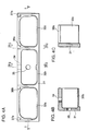
- Fig. 1A is a perspective view showing a part close to an end of a form member body 20 of a concrete form member according to an embodiment 1 of the present invention
- Fig. 1B is a perspective view of an end plate body 30 for engaging with the end of the form member body 20
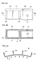
- Fig. 2 is a perspective view showing the end plate body 30 in a state engaging with the form member body 20.
- the form member body 20 according to this embodiment includes a flat strip-shaped main plate portion 21 and a horizontal pair of strip-shaped side plate portions 22a and 22b extending from both sides of the main plate portion 21 toward its rear surface (upper surface in Fig. 1A) perpendicularly to the main plate portion 21.
- Reinforcing plates 23a and 23b are provided between the horizontal pair of side plate portions 22a and 22b to extend from the rear surface of the main plate portion 21 substantially in parallel with the side plate portions 22a and 22b.
- the pair of side plate portions 22a and 22b have side plate enlarged end portions 25a and 25b inwardly enlarged in thickness over prescribed widths from opening ends (upper ends in Fig. 1A) thereof respectively.
- the reinforcing plates 23a and 23b have reinforcing plate enlarged end portions 26a and 2Gb, each enlarged in thickness toward at least one of the side plate portions 22a and 22b, over prescribed widths from opening ends thereof.
- the side plate enlarged end portions 25a and 25b are provided on lower end surfaces thereof with grooves 27a and 27b concaved toward the opening ends of the side plate portions 22a and 22b and extending along the longitudinal direction of the main plate portion 21.
- the reinforcing plate enlarged end portions 26a and 26b are also provided on lower end surfaces with grooves 28a and 28b similar to the grooves 27a and 27b.
- the form member body 20 of such a shape, having a uniform cross section, can be integrally formed by fiber-reinforced plastic through continuous draw molding.
- the reinforcing fiber preferably prepared from glass fiber, may be prepared from carbon fiber or aramid (trade name) fiber.
- the plastic component preferably prepared from polyester thermosetting resin, may be prepared from thermoplastic resin.
- the reinforcing plates 23a and 23b exhibit a reinforcing effect as ribs. Consequently, the form member body 20 is remarkably inhibited from bending deformation resulting from pressure of concrete in concrete placing in a plane parallel to the central longitudinal section thereof, whereby the form member body 20 can be reduced in thickness and weight.
- the end plate body 30 includes a shielding plate portion 31 and an engaging portion 32 as shown in Figs. 1B, 4A, 4B, 4C and 5, and the shielding plate portion 31 has a shape for shielding a longitudinal end of a space, having a rectangular cross section, enclosed with the main plate portion 21 and the pair of side plate portions 22a and 22b.
- the engaging portion 32 is formed by three tubular bodies 32a, 32b and 32c engaging with three spaces, having rectangular cross sections, partitioned by the reinforcing plates 23a and 23b respectively.
- Mounting holes 34 and 35 are provided on the central portion of the upper surface of the central tubular body 32b of the end plate body 31 and the central portion of the shielding plate portion 31 respectively, in order to receive clamp members for joining the form member with another form member or an end plate body engaging therewith. These mounting holes 34 and 35 are employed for assembling the concrete form having the cross-shaped concrete forming part 74 shown in Fig. 11, for example.
- the end plate body 30 having such a shape can also be prepared by integral forming of fiber-reinforced plastic, similarly to the form member body 20.
- the tubular bodies 32a and 32c forming the engaging portion 32 of the end plate body 30 are provided on upper end portions thereof with longitudinal projections 37a, 37b, 38a and 38b to tightly engage with the grooves 27a, 27b, 28a and 28b in the state engaging with the form member body 20.
- the grooves 27a, 27b, 28a and 28b and the longitudinal projections 37a, 37b, 38a and 38b tightly engage with each other in the engaging state of the form member body 20 and the end plate body 30, thereby inhibiting the side plate portions 22a and 22b of the form member body 20 from deformation in opening directions. Consequently, the form member body 20 is inhibited from bending deformation shown in Fig. 6C caused by pressure of concrete placed in the assembled form.
- flatness of a surface of formed concrete can be ensured without bringing another reinforcing member into contact with the form member body 20 when assembling the form.
- a concrete form can be assembled by oppositely arranging a pair of form member bodies 20 according to this embodiment and clamping the same with a form opposite space holder already proposed by the inventor in U.S. Patent No. 5,761,874.
- the form opposite space holder is formed by a separator 51, attachments 52 and clamp members 53.
- first ends of the clamp members 53 are inserted in the mounting holes 24 provided on the centers of the main plate portions 21 of the form member bodies 20 and female screws of the attachments 52 are fitted with male screws provided on both ends of the separator 51 while ends of the male screws provided on the ends of the separator 51 are fitted with female screws provided on second ends of the clamp members 53.
- the clamp members 53 clamp the separator 51 and the attachments 52 to the form member bodies 20.
- a form member connector shown in Fig. 8A already proposed by the inventor in European Patent Laying-Open No. EP0738808A1, can be employed for readily connecting/fixing two form member bodies 20 transversely arranged as shown in Fig. 8B, in order to temporarily fix these form member bodies 20 for assembling a form.
- a form member body 220 of the concrete form member according to this embodiment includes a main plate portion 221 and a pair of side plate portions 222a and 222b having shapes identical to those of the main plate portion 21 and the pair of side plate portions 22a and 22b of the form member body 20 according to the embodiment 1, while reinforcing plate enlarged end portions 226a and 226b provided on opening ends of reinforcing plates 223a and 223b are different in shape from those in the embodiment 1.
- the reinforcing plate enlarged end portions 226a and 226b of the reinforcing plates 223a and 223b of the form member body 220 according to this embodiment are provided with pairs of grooves 228a and 228b corresponding to the grooves 28a and 28b in a horizontally symmetrical manner.
- an end plate body 230 is provided with pairs of longitudinal projections 238a and 238b on upper ends of clearances 233a and 233b between adjacent tubular bodies 232a, 232b and 232c forming an engaging portion 232 in a horizontally symmetrical manner, to tightly engage with an end of the form member body 220.
- the pairs of grooves 228a and 228b are provided on the reinforcing enlarged end portions 226a and 226b of the reinforcing plates 223a and 223b of the form member body frame 220 in a horizontally symmetrical manner, thereby improving the reinforcing effect of the reinforcing plates 223a and 223b serving as ribs.
- an effect of inhibiting the form member body 220 from bending deformation in a plane parallel to the central longitudinal section thereof is further improved.
- the side plate portions 222a and 222b and the reinforcing plates 223a and 223b are further effectively prevented from deformation, to further remarkably improve the effect of inhibiting the form member body 220 from bending deformation in the plane parallel to the cross section thereof.
- a single reinforcing plate 323 may be provided substantially centrally between a pair of side plate portions 322a and 322b in a form member body 320 according to a modification of this embodiment, as shown in Fig. 10A.
- an engaging portion 332 of an end plate body 330 is formed by two tubular bodies 332a and 332b to tightly engage with an end of the form member body 320, as shown in Fig. 10B.
Landscapes
- Engineering & Computer Science (AREA)
- Architecture (AREA)
- Mechanical Engineering (AREA)
- Civil Engineering (AREA)
- Structural Engineering (AREA)
- Forms Removed On Construction Sites Or Auxiliary Members Thereof (AREA)
- Moulds, Cores, Or Mandrels (AREA)
- Surgical Instruments (AREA)
- Semiconductor Memories (AREA)
Applications Claiming Priority (2)
| Application Number | Priority Date | Filing Date | Title |
|---|---|---|---|
| JP6524698 | 1998-03-16 | ||
| JP10065246A JPH11256817A (ja) | 1998-03-16 | 1998-03-16 | コンクリート成形用型枠材 |
Publications (2)
| Publication Number | Publication Date |
|---|---|
| EP0943754A1 EP0943754A1 (en) | 1999-09-22 |
| EP0943754B1 true EP0943754B1 (en) | 2002-01-30 |
Family
ID=13281373
Family Applications (1)
| Application Number | Title | Priority Date | Filing Date |
|---|---|---|---|
| EP99103687A Expired - Lifetime EP0943754B1 (en) | 1998-03-16 | 1999-02-25 | Concrete form member |
Country Status (10)
| Country | Link |
|---|---|
| US (1) | US6296224B1 (xx) |
| EP (1) | EP0943754B1 (xx) |
| JP (1) | JPH11256817A (xx) |
| KR (1) | KR100419442B1 (xx) |
| CN (1) | CN1143042C (xx) |
| AT (1) | ATE212687T1 (xx) |
| CA (1) | CA2264512C (xx) |
| DE (1) | DE69900826T2 (xx) |
| HK (1) | HK1023170A1 (xx) |
| TW (1) | TW386128B (xx) |
Families Citing this family (19)
| Publication number | Priority date | Publication date | Assignee | Title |
|---|---|---|---|---|
| DE10007995C2 (de) * | 2000-02-22 | 2002-03-07 | Airbus Gmbh | Strukturbauteil, insbesondere für ein Flugzeug und Verfahren zur Herstellung eines Strukturbauteils |
| DE10160441B4 (de) * | 2001-12-08 | 2006-07-06 | Max Frank Gmbh & Co. Kg | Säulenschalung |
| US20040139677A1 (en) * | 2002-12-03 | 2004-07-22 | Francesco Mulas | Modular system for building structures |
| US8266856B2 (en) | 2004-08-02 | 2012-09-18 | Tac Technologies, Llc | Reinforced structural member and frame structures |
| US8065848B2 (en) | 2007-09-18 | 2011-11-29 | Tac Technologies, Llc | Structural member |
| US7721496B2 (en) * | 2004-08-02 | 2010-05-25 | Tac Technologies, Llc | Composite decking material and methods associated with the same |
| KR100743841B1 (ko) * | 2005-10-14 | 2007-07-30 | 박정진 | 조립식 거푸집패널, 그 연결구조 및 이를 이용한 대형벽체거푸집 |
| CA2551250A1 (en) * | 2005-11-18 | 2007-05-18 | Polyform A.G.P. Inc. | Stackable construction panel intersection assembly |
| MY168491A (en) * | 2006-11-15 | 2018-11-09 | Wendy Yong | A system of formwork and connecting means |
| JP5453645B2 (ja) * | 2009-07-06 | 2014-03-26 | 舩木商事有限会社 | 型枠パネルの隅部構造及びコンクリート型枠の構築方法 |
| US9458637B2 (en) * | 2012-09-25 | 2016-10-04 | Romeo Ilarian Ciuperca | Composite insulated plywood, insulated plywood concrete form and method of curing concrete using same |
| CN103912115A (zh) * | 2012-12-31 | 2014-07-09 | 王淼 | 建筑模板 |
| US10065339B2 (en) | 2013-05-13 | 2018-09-04 | Romeo Ilarian Ciuperca | Removable composite insulated concrete form, insulated precast concrete table and method of accelerating concrete curing using same |
| US10220542B2 (en) | 2013-05-13 | 2019-03-05 | Romeo Ilarian Ciuperca | Insulated concrete battery mold, insulated passive concrete curing system, accelerated concrete curing apparatus and method of using same |
| AU2014315033A1 (en) | 2013-09-09 | 2016-03-31 | Romeo Ilarian Ciuperca | Insulated concrete slip form and method of accelerating concrete curing using same |
| CN103758337A (zh) * | 2013-11-20 | 2014-04-30 | 大连大学 | 新型施工用定型板 |
| CN104481136A (zh) * | 2014-12-12 | 2015-04-01 | 新疆生产建设兵团第五建筑安装工程公司 | 一种多用途平板变形塑料建筑模板 |
| US10280622B2 (en) | 2016-01-31 | 2019-05-07 | Romeo Ilarian Ciuperca | Self-annealing concrete forms and method of making and using same |
| US11047143B2 (en) * | 2017-01-27 | 2021-06-29 | Meva Schalungs-Systeme Gmbh | Seal for a lead-through for a tie rod through a panel formwork element |
Family Cites Families (11)
| Publication number | Priority date | Publication date | Assignee | Title |
|---|---|---|---|---|
| BE637297A (xx) * | ||||
| CH294607A (de) * | 1951-08-23 | 1953-11-30 | Aeberli Albert | Demontierbare Konstruktion. |
| FR1219287A (fr) * | 1958-12-22 | 1960-05-17 | Pour La France Et L Etranger S | Perfectionnements aux dispositifs de coffrage |
| JPS6254149A (ja) | 1985-09-03 | 1987-03-09 | Mitsubishi Electric Corp | 核磁気共鳴映像法 |
| DE3703935A1 (de) * | 1986-11-21 | 1988-06-01 | Stefan Biffar | Geruestbrett und verfahren zu dessen herstellung |
| DE4009425A1 (de) * | 1990-03-23 | 1991-09-26 | Hollmann Niels | Betonierungs-schaltafel |
| US5537797A (en) * | 1993-11-22 | 1996-07-23 | The Salk Institute For Biological Studies | Modular concrete form system and method for constructing concrete walls |
| JP2717514B2 (ja) | 1994-04-28 | 1998-02-18 | 義行 早川 | コンクリート成形用型枠材 |
| JP2952181B2 (ja) | 1995-04-21 | 1999-09-20 | 義行 早川 | コンクリート成形用型枠材連結具 |
| JP2750846B2 (ja) | 1995-08-30 | 1998-05-13 | 義行 早川 | コンクリート型枠対向間隔保持固定用具 |
| DE19622149A1 (de) * | 1996-06-01 | 1997-12-04 | Stewing Nachrichtentechnik | Bauelement, insbesondere Schalplatte zur Herstellung von Betonschalungen |
-
1998
- 1998-03-16 JP JP10065246A patent/JPH11256817A/ja active Pending
-
1999
- 1999-02-09 TW TW088101998A patent/TW386128B/zh not_active IP Right Cessation
- 1999-02-25 EP EP99103687A patent/EP0943754B1/en not_active Expired - Lifetime
- 1999-02-25 DE DE69900826T patent/DE69900826T2/de not_active Expired - Fee Related
- 1999-02-25 AT AT99103687T patent/ATE212687T1/de active
- 1999-03-02 US US09/260,002 patent/US6296224B1/en not_active Expired - Fee Related
- 1999-03-04 CA CA002264512A patent/CA2264512C/en not_active Expired - Fee Related
- 1999-03-15 CN CNB991040198A patent/CN1143042C/zh not_active Expired - Fee Related
- 1999-03-16 KR KR10-1999-0008804A patent/KR100419442B1/ko not_active IP Right Cessation
-
2000
- 2000-04-20 HK HK00102400A patent/HK1023170A1/xx not_active IP Right Cessation
Also Published As
| Publication number | Publication date |
|---|---|
| US6296224B1 (en) | 2001-10-02 |
| DE69900826D1 (de) | 2002-03-14 |
| KR100419442B1 (ko) | 2004-02-19 |
| HK1023170A1 (en) | 2000-09-01 |
| TW386128B (en) | 2000-04-01 |
| CN1143042C (zh) | 2004-03-24 |
| CA2264512C (en) | 2004-11-23 |
| DE69900826T2 (de) | 2002-08-29 |
| JPH11256817A (ja) | 1999-09-21 |
| KR19990077926A (ko) | 1999-10-25 |
| EP0943754A1 (en) | 1999-09-22 |
| CA2264512A1 (en) | 1999-09-16 |
| ATE212687T1 (de) | 2002-02-15 |
| CN1233701A (zh) | 1999-11-03 |
Similar Documents
| Publication | Publication Date | Title |
|---|---|---|
| EP0943754B1 (en) | Concrete form member | |
| US5632923A (en) | Concrete molding form member | |
| KR100704779B1 (ko) | 리브홈 형강 및 그의 연결부재 | |
| JPH1046806A (ja) | コンクリート型枠パネル | |
| JPH0949320A (ja) | コンクリート型枠変形防止部材およびそれを用いたコンクリート型枠組立方法 | |
| KR200186899Y1 (ko) | 거푸집 | |
| KR200292763Y1 (ko) | 일체형 알루미늄 단위 거푸집판넬 | |
| KR100472603B1 (ko) | 콘트리트 측벽 거푸집 및 그의 결합구조 | |
| CN210508368U (zh) | 直阴角及应用该直阴角的建筑模板系统 | |
| CN216616636U (zh) | 一种垂直板式组件和板式结构 | |
| CA2206191C (en) | Wallform panel and side rail | |
| CN215167978U (zh) | 一种铝合金框建筑模板 | |
| CN214885175U (zh) | 一种收边过渡件 | |
| KR200294794Y1 (ko) | 콘트리트 측벽 거푸집 및 그의 결합구조 | |
| KR102402885B1 (ko) | 거푸집용 패널구조 | |
| CN212557236U (zh) | 一种承载装置的拼接结构 | |
| CN210101790U (zh) | 一种汽车底盘加强内板 | |
| CN211661928U (zh) | 用于把手组件的装配工装 | |
| KR0126589Y1 (ko) | 창호의 모서리부의 코너조립부재 | |
| KR200212583Y1 (ko) | 파렛트용 케스터 고정판 | |
| KR0177858B1 (ko) | 콘크리트 성형용 형틀재와, 그 조립에 이용되는 형틀재 간격유지구 및 형틀재 연결구 | |
| KR200315299Y1 (ko) | 창틀의 조립 구조 | |
| JPH0138197Y2 (xx) | ||
| JPH0522582Y2 (xx) | ||
| JPH0223708Y2 (xx) |
Legal Events
| Date | Code | Title | Description |
|---|---|---|---|
| PUAI | Public reference made under article 153(3) epc to a published international application that has entered the european phase |
Free format text: ORIGINAL CODE: 0009012 |
|
| AK | Designated contracting states |
Kind code of ref document: A1 Designated state(s): AT BE CH DE DK ES FI FR GB GR IE IT LI LU NL PT SE |
|
| AX | Request for extension of the european patent |
Free format text: AL;LT;LV;MK;RO;SI |
|
| 17P | Request for examination filed |
Effective date: 20000316 |
|
| AKX | Designation fees paid |
Free format text: AT BE CH DE DK ES FI FR GB GR IE IT LI LU NL PT SE |
|
| 17Q | First examination report despatched |
Effective date: 20000830 |
|
| GRAG | Despatch of communication of intention to grant |
Free format text: ORIGINAL CODE: EPIDOS AGRA |
|
| GRAG | Despatch of communication of intention to grant |
Free format text: ORIGINAL CODE: EPIDOS AGRA |
|
| GRAH | Despatch of communication of intention to grant a patent |
Free format text: ORIGINAL CODE: EPIDOS IGRA |
|
| GRAH | Despatch of communication of intention to grant a patent |
Free format text: ORIGINAL CODE: EPIDOS IGRA |
|
| GRAA | (expected) grant |
Free format text: ORIGINAL CODE: 0009210 |
|
| REG | Reference to a national code |
Ref country code: GB Ref legal event code: IF02 |
|
| AK | Designated contracting states |
Kind code of ref document: B1 Designated state(s): AT BE CH DE DK ES FI FR GB GR IE IT LI LU NL PT SE |
|
| PG25 | Lapsed in a contracting state [announced via postgrant information from national office to epo] |
Ref country code: NL Free format text: LAPSE BECAUSE OF FAILURE TO SUBMIT A TRANSLATION OF THE DESCRIPTION OR TO PAY THE FEE WITHIN THE PRESCRIBED TIME-LIMIT Effective date: 20020130 Ref country code: LI Free format text: LAPSE BECAUSE OF FAILURE TO SUBMIT A TRANSLATION OF THE DESCRIPTION OR TO PAY THE FEE WITHIN THE PRESCRIBED TIME-LIMIT Effective date: 20020130 Ref country code: IT Free format text: LAPSE BECAUSE OF FAILURE TO SUBMIT A TRANSLATION OF THE DESCRIPTION OR TO PAY THE FEE WITHIN THE PRESCRIBED TIME-LIMIT;WARNING: LAPSES OF ITALIAN PATENTS WITH EFFECTIVE DATE BEFORE 2007 MAY HAVE OCCURRED AT ANY TIME BEFORE 2007. THE CORRECT EFFECTIVE DATE MAY BE DIFFERENT FROM THE ONE RECORDED. Effective date: 20020130 Ref country code: GR Free format text: LAPSE BECAUSE OF FAILURE TO SUBMIT A TRANSLATION OF THE DESCRIPTION OR TO PAY THE FEE WITHIN THE PRESCRIBED TIME-LIMIT Effective date: 20020130 Ref country code: FI Free format text: LAPSE BECAUSE OF FAILURE TO SUBMIT A TRANSLATION OF THE DESCRIPTION OR TO PAY THE FEE WITHIN THE PRESCRIBED TIME-LIMIT Effective date: 20020130 Ref country code: CH Free format text: LAPSE BECAUSE OF FAILURE TO SUBMIT A TRANSLATION OF THE DESCRIPTION OR TO PAY THE FEE WITHIN THE PRESCRIBED TIME-LIMIT Effective date: 20020130 Ref country code: BE Free format text: LAPSE BECAUSE OF FAILURE TO SUBMIT A TRANSLATION OF THE DESCRIPTION OR TO PAY THE FEE WITHIN THE PRESCRIBED TIME-LIMIT Effective date: 20020130 Ref country code: AT Free format text: LAPSE BECAUSE OF FAILURE TO SUBMIT A TRANSLATION OF THE DESCRIPTION OR TO PAY THE FEE WITHIN THE PRESCRIBED TIME-LIMIT Effective date: 20020130 |
|
| REF | Corresponds to: |
Ref document number: 212687 Country of ref document: AT Date of ref document: 20020215 Kind code of ref document: T |
|
| REG | Reference to a national code |
Ref country code: CH Ref legal event code: EP |
|
| PG25 | Lapsed in a contracting state [announced via postgrant information from national office to epo] |
Ref country code: LU Free format text: LAPSE BECAUSE OF NON-PAYMENT OF DUE FEES Effective date: 20020225 |
|
| REF | Corresponds to: |
Ref document number: 69900826 Country of ref document: DE Date of ref document: 20020314 |
|
| REG | Reference to a national code |
Ref country code: IE Ref legal event code: FG4D |
|
| PG25 | Lapsed in a contracting state [announced via postgrant information from national office to epo] |
Ref country code: SE Free format text: LAPSE BECAUSE OF FAILURE TO SUBMIT A TRANSLATION OF THE DESCRIPTION OR TO PAY THE FEE WITHIN THE PRESCRIBED TIME-LIMIT Effective date: 20020430 Ref country code: PT Free format text: LAPSE BECAUSE OF FAILURE TO SUBMIT A TRANSLATION OF THE DESCRIPTION OR TO PAY THE FEE WITHIN THE PRESCRIBED TIME-LIMIT Effective date: 20020430 Ref country code: DK Free format text: LAPSE BECAUSE OF FAILURE TO SUBMIT A TRANSLATION OF THE DESCRIPTION OR TO PAY THE FEE WITHIN THE PRESCRIBED TIME-LIMIT Effective date: 20020430 |
|
| ET | Fr: translation filed | ||
| NLV1 | Nl: lapsed or annulled due to failure to fulfill the requirements of art. 29p and 29m of the patents act | ||
| PG25 | Lapsed in a contracting state [announced via postgrant information from national office to epo] |
Ref country code: ES Free format text: LAPSE BECAUSE OF FAILURE TO SUBMIT A TRANSLATION OF THE DESCRIPTION OR TO PAY THE FEE WITHIN THE PRESCRIBED TIME-LIMIT Effective date: 20020730 |
|
| REG | Reference to a national code |
Ref country code: CH Ref legal event code: PL |
|
| PLBE | No opposition filed within time limit |
Free format text: ORIGINAL CODE: 0009261 |
|
| STAA | Information on the status of an ep patent application or granted ep patent |
Free format text: STATUS: NO OPPOSITION FILED WITHIN TIME LIMIT |
|
| 26N | No opposition filed | ||
| PGFP | Annual fee paid to national office [announced via postgrant information from national office to epo] |
Ref country code: IE Payment date: 20070221 Year of fee payment: 9 |
|
| PGFP | Annual fee paid to national office [announced via postgrant information from national office to epo] |
Ref country code: FR Payment date: 20070216 Year of fee payment: 9 |
|
| PGFP | Annual fee paid to national office [announced via postgrant information from national office to epo] |
Ref country code: GB Payment date: 20080222 Year of fee payment: 10 Ref country code: DE Payment date: 20080229 Year of fee payment: 10 |
|
| REG | Reference to a national code |
Ref country code: IE Ref legal event code: MM4A |
|
| REG | Reference to a national code |
Ref country code: FR Ref legal event code: ST Effective date: 20081031 |
|
| PG25 | Lapsed in a contracting state [announced via postgrant information from national office to epo] |
Ref country code: IE Free format text: LAPSE BECAUSE OF NON-PAYMENT OF DUE FEES Effective date: 20080225 |
|
| PG25 | Lapsed in a contracting state [announced via postgrant information from national office to epo] |
Ref country code: FR Free format text: LAPSE BECAUSE OF NON-PAYMENT OF DUE FEES Effective date: 20080229 |
|
| GBPC | Gb: european patent ceased through non-payment of renewal fee |
Effective date: 20090225 |
|
| PG25 | Lapsed in a contracting state [announced via postgrant information from national office to epo] |
Ref country code: DE Free format text: LAPSE BECAUSE OF NON-PAYMENT OF DUE FEES Effective date: 20090901 |
|
| PG25 | Lapsed in a contracting state [announced via postgrant information from national office to epo] |
Ref country code: GB Free format text: LAPSE BECAUSE OF NON-PAYMENT OF DUE FEES Effective date: 20090225 |