-
The present invention relates to a method of
fabricating a plastic mask for paste printing for forming
patterns by use of an ink, an adhesive agent, a solder
paste, or a paste-like resin (hereinafter referred to as
the paste) on a printing material, more particularly to a
method of fabricating a plastic mask for such paste
printing, which is carried out by forming a pattern of
through-holes in a plastic sheet by excimer laser
abrasion.
-
The present invention also relates to a plastic mask
fabricated by the above-mentioned method, and also to a
paste printing method by use of the plastic mask.
-
For forming a printed pattern on a printing material
with the above-mentioned paste by use of a printing mask,
the following method is generally used:
-
A printing mask with a pattern of through-holes is
brought into close contact with a printing material, and
a paste is spread on the surface of the printing mask by
a squeegee so as to fill the through-holes with the
paste. An excessive paste is then removed from the
surface of the printing mask.
-
The printing mask is then separated from the
printing material in such a manner that the paste passes
through the through-holes and remains in the same pattern
as that of the through-holes formed in the printing mask
on the printing material, whereby a paste pattern
corresponding to the pattern of the through-holes is
printed on the surface of the printing material.
-
Such printing masks for use in practice can be
roughly classified into screen masks and metal masks.
-
As screen masks, there are known, for example, punch
press mask, YAG laser mask, etching mask, additive mask
and half-etching mask.
-
The punch press mask was developed as a solder paste
printing mask for fabricating electronic parts. The
punch press mask can be prepared by forming round
through-holes in a metal sheet with a punch.
-
This printing mask can be easily and quickly
prepared by utilizing NC data of a mounter used in a
mounting process with high through-hole making speed.
-
This printing mask has the advantages over other
printing masks that the production method is simple and
therefore the printing mask can be produced at extremely
low cost. Furthermore, the apparatus for producing the
printing mask is also inexpensive and small-sized and
therefore can be brought into and used in a printing
facility without difficulty.
-
Despite such advantages, this printing mask has the
shortcomings that upper edge portions of the through-holes
tend to be rounded, and rough broken surfaces or
burr tends to be formed in the lower edge portions of the
through-holes, so that the paste filled in the through-holes
cannot smoothly pass through the through-holes and
therefore the printing quality is poor.
-
A minimum diameter of the through-hole that can be
formed is about 0.3 mm. For example, in the solder paste
printing for fabricating electronic parts, a minimum
pitch will be about 0.5 mm in QFP (quad flat package) at
best.
-
A YAG laser mask is prepared by fusing a metal sheet
(usually SUS) with YAG laser and fused portions in the
metal sheet are blown off by use of an assist gas to form
through-holes in the metal sheet.
-
In the case of the YAG laser mask, through-holes are
made in accordance with the NC data or the like, so that
the YAG laser mask has the advantage that the mask can be
produced in a short time with a minimum dispersion in
quality, but has the disadvantages that the inner walls
of the through-holes are rough, and dross is deposited at
the edge portions of the through-holes, so that the
printing quality obtained by the YAG laser mask is
slightly inferior to that obtained by other printing
masks.
-
Furthermore, convex portions are formed in the edge
portions by the deposition of the dross thereon, and the
thus formed convex portions tend to make imperfect the
contact of the printing mask with a printing material
during the printing process. If such imperfect contact
takes place, it is necessary to remove the convex
portions from the edge portions by grinding or polishing
the surface of the printing mask.
-
An etching mask is prepared as follows: A photosensitive
resin is coated on both sides of a metal plate
to form resist layers thereon. The resist layers are
exposed to light through a photomask on which through-holes
are depicted in a pattern (hereinafter referred to
as the through-hole pattern depicted photomask) and are
then developed by removing the portions corresponding to
the through-hole pattern from the resist layers. This
metal plate is then subjected to etching, whereby
through-holes are made in the same pattern as the above-mentioned
through-hole pattern in the metal plate. Thus,
an etching mask for printing is prepared. In the thus
prepared etching mask, etching is carried out on both
sides of the metal plate for making the through-holes
therein, so that a convex portion is formed at the
central portion of the inner wall of each through-hole.
Furthermore, the inner wall of the through-hole is rough,
so that a paste cannot smoothly pass through each
through-hole. The result is that the printing quality
obtained by the thus prepared etching mask is poor.
-
An additive mask is prepared as follows: A
relatively thick photosensitive resin layer or dry film
layer is provided on a plating substrate. The photosensitive
resin layer is exposed to light through a
through-hole pattern depicted photomask and developed by
removing the portions in the photosensitive resin layer
except the portions corresponding to the through-hole
pattern. Thus, the photosensitive resin layer portions
remain in the through-hole pattern on the plate
substrate. A metal plate, for example, made of nickel,
with an appropriate thickness, is formed by plating
around the photosensitive resin layer portions which
remain in the through-hole pattern. The metal plate is
then removed from the plating substrate, and the photosensitive
resin layer portions are dissolved away from
the metal plate, whereby a metal plate with through-holes
which correspond to the removed photosensitive resin
layer portions is prepared as a printing mask.
-
The inner walls of the through-holes formed in the
above metal plate are the smoothest than any of the inner
walls of through-holes formed in metal masks prepared by
any other methods and accordingly, the printing quality
obtained by the metal plate is relatively good. However,
occasionally, the inner walls of the through-holes are
roughened by the over-exposure of the dry film, which may
be referred to as "attack phenomenon".
-
It is considered that the "attack phenomenon" is
caused as follows. It is necessary that the photo-sensitive
resin layer or dry film for the formation of
the through-holes in the printing mask be sufficiently
thicker than the additive mask. Occasionally, the
thickness of the photosensitive resin layer may be 200 µm
or more. Since this thickness is much greater than that
of a photosensitive resin layer for the masking of an
etching liquid, which is in the range of 20 to 30 µm, a
sufficient amount of light must be applied so as to have
the light reach the bottom portion of the photosensitive
resin layer on the side of the substrate. For this
reason, light with high intensity is applied to the
uppermost surface of the photosensitive resin layer on
the side of the photomask.
-
When the above-mentioned light applied to the
uppermost side of the photosensitive resin layer causes
halation within the photosensitive resin layer, the
portions which should be shaded by the photomask are
exposed to the light scattered from the adjacent portions
within the photosensitive resin layer. As a result, the
inner walls of the through-holes are roughened as
mentioned above.
-
Furthermore, stepped portions are formed in the
inner walls of the through-holes with the attachment of
the dry film thereto while in use, whereby the printing
quality is lowered.
-
The plated surface of the printing metal plate which
comes into contact with a printing material tends to be
roughened. In particular, when finely-divided particles
are contained in a paste for printing, such as in a
solder paste, and such a paste spreads, the finely-divided
particles in the paste enter the roughened
portions at the plated surface of the mask and are fixed
thereon, so that the roughness of the surface is further
intensified. The result is that the close contact with
the printing metal plate with the printing material is
hindered, and the spreading of the paste is further
increased.
-
On the other hand, one of the most representative
materials used as plating materials in the additive mask
is nickel. Nickel is softer than stainless steel
(usually SUS 304) which is frequently used as a material
for an etching mask, so that the portions near minute
through-holes are easily deformed by the convex portions
in the roughened surface or by some foreign materials,
whereby the printing quality tends to be easily degraded.
-
As a countermeasure to avoid this problem, the
hardness of the additive mask is increased, for example,
with the addition of cobalt thereto at the time of
plating. This countermeasure, however, tends to increase
the roughness of the plated surface and to promote the
above-mentioned fixing of the finely-divided particles in
the paste, thereby increasing the spreading of the paste.
-
A half-etching mask is used for printing, particularly
a solder paste in print-circuit boards for
electronic parts. In this field, it is required that a
mixture of large and micro electronic parts be mounted in
accordance with the recent tendency that electronic parts
are small-sized. When solder paste printing is performed
for micro electronic parts, it is required that the
printing mask be made thin and that micro through-holes
be formed in the printing mask and filled with the solder
paste; while when solder paste printing is performed for
relatively large parts, it is required that the printing
mask be made thick and that relatively large through-holes
be formed in the printing mask and filled with the
solder paste.
-
When solder paste printing is performed on a print-circuit
board on which large parts and micro parts are to
be mixedly mounted, by use of a thin printing mask for
solder printing for micro parts, the solder paste for the
large parts quickly runs out; while when solder paste
printing is performed on the print-circuit board by use
of a thick printing mask for solder printing for large
parts, the solder paste does not smoothly pass through
the micro through-holes for the micro parts, and even if
the solder paste passes through the micro through-holes,
excellent paste printing cannot be performed due to the
presence of excessive solder paste.
-
It is the half-etching mask that can solve the
above-mentioned problems since it is partially made thin
by etching and paste printing for large parts and that
for micro parts can be performed by use of one and the
same printing mask.
-
The half-etching mask is prepared as follows:
First of all, in accordance with the previously mentioned
method for preparing the additive mask, there is prepared
a printing mask with a necessary thickness for large
parts, micro through-holes for micro parts, and
relatively large through-holes for large parts.
-
The micro through-holes within a half-etching area
are filled with a resin for protecting inner walls of the
micro through-holes.
-
The area except the half etching area, for which
etching is unnecessary, is masked by use of a resist
agent, and then etching is performed until the thickness
of the etched area reaches a suitable thickness for the
micro parts, whereby a thin printing mask is prepared
only in the area where micro through-holes for micro
parts are formed.
-
Such a half-etching mask has made it possible to
perform solder paste printing for large, normal, and
micro electronic parts by use of one and the same
printing mask in the field of electronic part mounting.
On the other hand, even if the micro through-holes are
filled with the resin for protecting the inner walls
thereof, the spreading of the etching liquid cannot be
completely prevented, so that the smooth inner walls made
by the additive method are roughened by the spread
etching liquid. The result is that the half-etching mask
tends to have the shortcomings that the micro through-holes
for most precise printing are most roughened and
accordingly the printing quality is lowered.
-
Furthermore, the above-mentioned process for
preparing the half-etching mask includes the step of
carrying out the additive method, so that the previously
mentioned shortcomings of the additive method may also
appear in the above-mentioned process. Namely, the
additive method has the shortcomings that the inner walls
of the through-holes are roughened by the over-exposure
of the dry film, or stepped portions are formed in the
inner walls of the through-holes with the attachment of
the dry film thereto while in use, whereby the printing
quality is lowered.
-
Furthermore, the above-mentioned metal masks, such
as punch press mask, YAG laser mask and etching mask,
lack flexibility, so that when a printing material has
convex portions on the surface thereof, even if it is
tried to bring such a printing mask into close contact
with the printing material, there are formed gaps between
the printing mask and the printing material. Therefore,
when the through-holes in the printing mask are filled
with a paste, the paste enters the gaps between the
printing mask and the printing material, so that the
printed paste pattern improperly spreads. Furthermore,
when a paste containing solid particles is employed, the
solid particles adhere to the back side of the mask, and
during the repeated printing by use of the mask, the
adhering solid particles make a gap between the printing
mask and the printing material, so that the improper
spreading of the printed paste pattern is further
increased.
-
Metal sheets (mainly a nickel sheet), such as the
additive mask and the half-etching mask, which are
prepared by plating, are flexible, so that when such a
metal sheet is brought into close contact with a printing
material, even if there are foreign materials or convex
portions on the surface of the printing material, the
mask can be easily deformed so as to be in close contact
therewith. Therefore, when a portion near the through-holes
of the mask is deformed and the mask is repeatedly
used for printing, the paste enters behind the mask from
the deformed portion thereof. The result is that the
printed paste patterns spread and the printing quality is
lowered.
-
Furthermore, the thicker the plated layer, the
rougher the surface of the plated layer. In particular,
when the paste contains solid particles which can be
easily deformed, such as solder particles, such solid
particles enter between the mask and the printing
material and are depressed therebetween. The depressed
solid particles adhere to the rough surface of the mask.
When such a printing mask is repeatedly used for
printing, the adhering solid particles form gaps between
the printing mask and the printing material. When the
through-holes of the mask are filled with a paste, the
paste enters the gaps between the printing mask and the
printing material, so that the printed paste pattern
spreads.
-
When the adhering solid particles overflow out of
the through-holes, the paste does not easily pass through
the through-holes, so that the printing quality of the
paste is degraded.
-
In the case where a paste enters the gap between a
printing mask and a printing material, and the paste or
solid particles contained in the paste adhere to the back
side of the printing mask, it is required to wipe off the
paste which adheres to the back side of the printing mask
or to clean the back side of the printing mask quite
often, especially when the printing mask is used
repeatedly.
-
In accordance with the recent trend that electronic
appliances and parts are made smaller and smaller in
size, demands for highly precise paste printing of micro
patterns with high quality free from non-printing
portions or chips and spreading, are increasing in the
field of the application of paste printing to electronic
appliances and the like.
-
In order to solve the previously mentioned various
problems of the conventional metal masks and to perform
precise paste printing with high quality, thereby meeting
the above-mentioned demands, the inventor of the present
invention has prepared a plastic mask for paste printing
by forming through-holes in a predetermined pattern in a
plastic sheet by excimer laser abrasion, and has
conducted paste printing by use of the plastic mask
prepared by excimer laser abrasion. As a result, it has
been discovered that the previously mentioned various
problems of the conventional metal masks can be solved by
the plastic mask.
-
Through-holes can be formed in a plastic sheet by
excimer laser abrasion, so that the through-holes formed
in the plastic sheet are free from burr in the edges and
deposition of dross as in the through-holes in the
conventional metal masks, and also free from non-clear-cut
edges as in the through-holes formed in the
conventional punch press mask.
-
Furthermore, the inner walls of the through-holes
formed in the plastic mask are extremely smooth and the
formed through-holes themselves are precise and clean.
-
In a conventional metal mask made of stainless steel
(usually SUS304), the surface of the metal mask is
subjected to hair-line finishing or crape finishing.
Further, in the case where the metal mask is made of an
electro-forming nickel, the surface of the metal mask is
rough. In such a case, it may occur that fine particles,
for example, solder particles, contained in a solder
paste which is spread onto the back side of the mask, are
depressed between the mask and a printing material, so
that the depressed particles are fixed to the rough
surface of the metal mask. This is apt to occur at the
convex portions in the printing surface of the mask where
the paste tends to spread. When this takes place, the
contact of the mask with the printing material become
imperfect, so that the spreading of the paste is
increased.
-
In contrast to this, in the case of the plastic
mask, the surface thereof can be easily made extremely
smooth, so that the fine particles contained in the paste
are hardly fixed to the surface of the plastic mask.
This significant feature of the plastic mask makes it
possible to attain (a) close contact of the mask with a
printing material, (b) significant reduction of the
spreading of the paste, and (c) improvement of continuous
printing performance.
-
Further, by use of the plastic mask, a so-called
"half-etching mask" can be easily prepared, in which
a portion of the plastic sheet on the side with which a
squeegee comes into contact is partially made thin, and a
predetermined pattern of through-holes for micro parts is
formed in the partially thinned portion.
-
The plastic mask is softer and more flexible than
the metal masks and therefore can flexibly follow up any
convex and concave portions on a printing surface to
attain close contact therewith without any gap or with a
minimum gap between the mask and the printing surface.
-
Furthermore, since the plastic mask is flexible,
when it is peeled away from the printing surface, the
plastic mask can immediately return to its original flat
shape. In other words, in the plastic mask, there occurs
no deformation as in a metal mask such as a nickel sheet
formed by plating, when the mask is brought into close
contact with a printing surface with convex and concave
portions thereon.
-
Therefore, by performing paste printing by use of
the plastic mask, the through-holes in the plastic mask
can be completely filled with the paste, and when the
plastic mask is removed from the printing material, the
filled paste can pass through each through-hole in a
complete shape, and the formation of gaps between the
plastic mask and the printing surface can be minimized,
so that on the printing surface, there can be formed a
paste pattern which accurately corresponds to the pattern
of the through-holes formed in the mask and is free from
any spreading of the paste, whereby highly precise, high
quality paste printing can be performed.
-
However, there are the following problems in the
production of the plastic mask and also in the paste
printing by use of the plastic mask:
- (1) The plastic mask is usually prepared by placing a
plastic sheet on a working table, then bringing the
plastic sheet into close contact with the surface of the
working table, and forming through-holes in the plastic
sheet with the irradiation with an excimer laser beam
from above the plastic sheet. In this method, however,
in a portion of the plastic sheet with which the working
table is not sufficiently in close contact, occasionally,
there occurs that a plastic thin film remains at the
bottom of through-holes made in the plastic sheet, which
is hereinafter referred to as the "thin-film remaining
phenomenon"; and in a portion of the plastic sheet with
which the working table is completely in close contact,
there occurs that the lower edges of the formed through-holes
are rounded, which is hereinafter referred to as
the "edge-rounding phenomenon".
When a through-hole is made in the plastic sheet by
excimer laser, the through-hole is usually tapered with
the opening of the through-hole becoming narrower in the
direction from the upper opening to the lower opening
thereof.When paste printing is performed in practice by use
of a plastic mask with such through-holes, the plastic
mask is reversed upside down in such a manner that the
narrower opening of the through-hole comes to the upper
side and the larger opening of the through-hole comes to
the lower side.When the "thin-film remaining phenomenon" takes
place, the presence of the remaining thin film at the
upper end portion of the hole hinders the filling of the
hole with the paste and the passing of the paste through
the hole, thereby making it impossible to perform paste
printing with high quality and high precision.Furthermore, when the "edge-rounding phenomenon"
takes place, the rounded edge of the upper opening of the
through-hole hinders the filling of the through-hole with
the paste and the passing of the paste through the
through-hole, thereby making it impossible to perform
paste printing with high quality and high precision.
- (2) The plastic mask is made of an insulating material
and is softer than a metal, and therefore has problems
due to the generation of electrostatic charges by the
friction between the plastic mask and a squeegee during
paste printing, and also due to abrasion resistance,
which problems are not found in the metal masks:
As shown in Figs. 32 and 33, when paste printing is
performed, a paste 16 is spread on the surface of a
plastic mask 50 by a squeegee 27, so that the through- holes
19, 20 and 21 arranged in a pattern in the plastic
mask 50 are filled with the paste 16. As the squeegee
27, a soft and elastic squeegee made of, for example,
urethane resin, is usually employed in order that the
squeegee 27 can come into close contact with the surface
of a thin half-etching portion 22 of the plastic mask 50,
or in order that the squeegee 27 can come into close
contact with the plastic mask 50 even if a printing
material includes convex and concave portions at the
surface thereof, or a curved surface. A squeegee made of
urethane resin is an electrically insulating material.Therefore, when friction is caused between the
urethane squeegee and the surface of the plastic mask 50
during paste printing, the surface of the urethane
squeegee and that of the plastic mask 50 are charged by
the electrostatic charges generated at the respective
surfaces thereof.In the case of metal masks, since the metal masks
themselves are electroconductive, there are almost no
problems concerning the electrostatic charging. In
contrast to this, in the case of the plastic mask, since
the plastic mask itself is an electrically insulating,
problems caused by the electrostatic charging are
unavoidable. In particular, serious problems such as
electrostatic destruction of inner circuits are caused
during actual operations for mounting electronic parts on
print-circuit boards by duplex reflow soldering.Duplex reflow soldering is performed as follows:
A solder paste is printed on one side of a print-circuit
board. Electronic parts are then mounted thereon by
utilizing the viscosity of the solder paste. The
electronic-parts-mounted print-circuit board is then
passed through an electric furnace called "reflow
furnace", whereby the solder paste is fused and the
electronic parts are soldered on one side of the print-circuit
board. This print-circuit board is turned upside
down, and the above-mentioned soldering process is
repeated on the opposite side of the print-circuit board,
whereby electronic parts are soldered on both sides of
the print-circuit board.When the plastic mask is used in solder paste
printing in the above-mentioned duplex reflow soldering,
the following problems are caused:Electrostatic charges generated by the use of the
plastic mask are built up to reach a high potential in
the plastic mask as triboelectric charging is repeated by
the printing process. The thus built-up electrostatic
charges flow into the electronic parts which are already
mounted on one side of the print-circuit board, and when
the electric charges reach a certain potential, there is
the risk that micro circuits within the electronic parts
are subjected to electrostatic destruction.Some electronic parts which are soldered by the
above-mentioned duplex reflow soldering are extremely
vulnerable to electrostatic charges. For example, ROM,
RAM, CMOS products and CCD are known as being apt to be
subjected to electrostatic destruction by electrostatic
charges of one hundred and several tens volts.When a solder paste is printed on a glass epoxy
substrate by use of a plastic mask without antistatic
treatment and an urethane squeegee, the voltage of
electrostatic charges built on the surface of the plastic
mask actually exceeds as high as 1000 volts during 3 to 4
times printing operations. There is the risk that the
previously mentioned electronic parts may be subjected to
electrostatic destruction by the electrostatic charges
with the above-mentioned high voltage.Furthermore, with respect to the electronic parts
which are electrostatically destroyed, the occurrence of
the problems cannot be recognized from the external
appearance thereof, and the problems are discovered
during function inspection which is almost the final step
of the mounting of the electronic parts, so that an
enormous loss is incurred when the discovery of such
problems is delayed.The electrostatic destruction within the memory
circuits such as ROM and RAM cannot be discovered by
normal function inspection, so that there is the risk
that inferior products may be put on the market.As a countermeasure for avoiding the above-mentioned
problems caused by electrostatic charging, the use of a
squeegee made of a metal may be considered. To be more
specifically, as the squeegee, a metal plate made of
phosphor bronze may be used in an attempt to dissipate
the electrostatic charges built on the surface of the
plastic mask through such an electroconductive metal
squeegee.However, as shown in Fig. 34, a metal squeegee 67 is
not as flexible as an urethane squeegee, so that when
printing is performed at the half-etching portion 22
which is thinner than the other portion 51, the lower end
portion of the metal squeegee 67 above the half-etching
portion 22 passes over the thinner half-etching portion
22 without coming into close contact with the half-etching
portion 22, since the other lower end portion of
the metal squeegee 67 is supported on the other portion
51 which is thicker than the half-etching portion 22, so
that a thin film of the solder paste 16 remains on the
half-etching portion 22.As a result, when the plastic mask 50 is peeled away
from the printing surface, a thin film of the solder
paste 16 remains on the half-etching portion 22 and
hinders the passing of the solider paste 16 from the
micro through-holes formed in the half-etching portion 22
as illustrated in Fig. 35. Therefore, the metal squeegee
is not suitable for paste printing by use of a plastic
mask including a half-etching portion, so that there is
no choice but to use a plastic squeegee such as an
urethane squeegee, and in such a case, the previously
mentioned problems are caused by the triboelectric
charging of the plastic squeegee.Furthermore, since the plastic mask is softer than
the metal masks, the plastic mask is inferior to the
metal masks with respect to the abrasion resistance. In
particular, when the printing material is a material
having a rough surface, such as a ceramic plate and a
glass epoxy layered substrate, or when hard and fine
chips of the material for the substrate are present at
the surface of the substrate, the abrasion of the plastic
mask proceeds further quickly.
- (3) A soft and elastic squeegee, such as a squeegee made
of urethane resin, is usually used in order to bring the
squeegee into close contact with the thin half-etching
portion 22, since the paste 16 is spread on the surface
of the plastic mask 50 as illustrated in Figs. 32 and 33.
-
-
Further as shown in Fig. 32, various sized through-holes,
such as a large through-hole 19 and a medium
through-hole 20 and a micro through-hole 21, are formed
in the plastic mask 50 in such arrangement that
corresponds to the arrangement of the connection
terminals of electronic parts to be soldered. As
illustrated in Fig. 36, when such through-holes are slit-shaped
through-holes 41 which are formed side by side
with a narrow rib 38 between each slit-shaped through-hole
41, and an urethane squeegee 27 passes over the
slit-shaped through-holes 41 in contact therewith as
illustrated in Fig. 37, the urethane squeegee 27 proceeds
as the tip of the elastic urethane squeegee 27 slightly
enters each of the slit-shaped through-holes 41 and
catches each narrow rib 38, so that each rib 38 is bent
as illustrated in Fig. 38. This is particularly apt to
occur in small slit-shaped through-holes formed in a
half-etching portion. This occurs more easily when the
edge of the squeegee is directed so as to be in agreement
with the longer side of the slit-shaped through-holes, in
such a manner that the squeegee 27 is moved in the
direction of the arrow as illustrated in Fig. 38.
-
When printing is performed as the ribs 38 are
successively bent, the amount of the paste to be printed
and the printing positions cannot be controlled properly.
In the worst case, printing is carried out in such a
manner that the adjacent slit-shaped through-holes are
connected. Furthermore, if the bending of the ribs is
repeated as the printing is performed, the base portions
of each rib may be broken because of the fatigue thereof.
-
It is therefore a first object of the present
invention to provide a method of fabricating a plastic
mask which is capable of performing paste printing with
high quality and high precision by forming precise and
fine through-holes in a plastic sheet, which are free
from the "thin-film remaining phenomenon", the "edge-rounding
phenomenon" and burr in the through-holes, or in
which the "thin-film remaining phenomenon", the "edge-rounding
phenomenon" and burr in the through-holes are
minimized, and therefore have excellent paste passing
performance.
-
A second object of the present invention is to
provide the above-mentioned plastic mask.
-
A third object of the present invention is to
provide a paste printing method capable of performing
paste printing a precise through-hole pattern with high
quality and high precision by use of the above-mentioned
plastic mask.
-
A fourth object of the present invention is to
provide a plastic mask with excellent antistatic
performance and excellent abrasion resistance, and to
provide a paste printing method by use of this plastic
mask.
-
A fifth object of the present invention is to
provide a plastic mask with slit-shaped through-holes
with the bending of the ribs for the through-holes being
minimized, thereby preventing improper printing and the
breaking of the base portions of the ribs due to the
fatigue thereof which may be caused by the repeated
bending of the ribs, and to provide a paste printing
method by use of the above plastic mask.
-
The above objects of the present invention can be
achieved by the following plastic mask fabricating
methods, plastic masks, paste printing methods and
plastic masks therefor:
-
A method of fabricating a plastic mask for paste
printing of the present invention is a plastic mask
fabricating method with a plastic sheet being irradiated
with an excimer laser beam for forming at least one
penetrating opening containing area comprising at least
one through-hole in the plastic sheet, comprising the
steps of (1) bringing a polymer film capable of absorbing
at least part of the excimer laser beam into close
contact with a back surface of the plastic sheet which is
opposite to an excimer laser beam irradiation side
thereof which is to be irradiated with the excimer laser
beam; (2) forming at least one penetrating opening
containing area comprising at least one through-hole in
the plastic sheet by irradiating the excimer laser beam
irradiation side thereof with the excimer laser beam; and
(3) removing the polymer film from the plastic sheet
after the formation of the penetrating opening containing
area.
-
In the above-mentioned plastic mask fabrication
method, the polymer film may be releasably stuck on the
back surface of the plastic sheet opposite to the excimer
laser beam irradiation side thereof.
-
A plastic mask for paste printing of the present
invention comprises a plastic sheet comprising at least
one penetrating opening containing area which comprises
at least one through-hole therein, the penetrating
opening containing area being formed by the plastic sheet
being irradiated with an excimer laser beam, with the
depth of each of the through-holes in the penetrating
opening containing area measured from the top surface of
the plastic mask to the narrowest portion of each of the
through-holes in the penetrating opening containing area
being 10 µm or less.
-
The above-mentioned plastic mask of the present
invention may have a thickness of 10 to 500 µm and a
modulus of bending elasticity of 20 to 500 Kgf·mm-2.
-
A paste printing method of the present invention
comprises the steps of (1) bringing a paste printing mask
comprising at least one penetrating opening containing
area which comprises at least one through-hole into close
contact with a printing material; (2) filling each of the
through-holes in the penetrating opening containing area
with a paste comprising solid particles by spreading and
pressing the paste on the paste printing mask; and (3)
removing the paste printing mask from the printing
material, thereby forming on the printing material a
paste pattern in the same pattern as that of the through-holes
in the penetrating opening containing area, wherein
as the paste printing mask, there is employed a plastic
mask for paste printing provided with a penetrating
opening containing area, the penetrating opening
containing area being formed in a plastic sheet so as to
include at least one through-hole by excimer laser beam
abrasion, with the depth of each of the through-holes of
the penetrating opening containing area measured from the
top surface of the plastic mask to the narrowest portion
of each of the through-holes in the penetrating opening
containing area being 1/2 or less the particle size of
the solid particles contained in the paste.
-
In the above-mentioned paste printing method, the
plastic mask for paste printing may have a thickness of
10 to 500 µm and a modulus of bending elasticity of 20 to
500 Kgf·mm-2.
-
A plastic mask for paste printing of the present
invention comprises a plastic sheet with a penetrating
opening containing area comprising at least one through-hole;
and an electroconductive layer formed on at least
one of the opposite upper and lower surfaces of the
plastic sheet.
-
In the above-mentioned plastic mask, the electroconductive
layer may be provided on one of the opposite
surfaces of the plastic sheet with which surface a
printing material is to come into contact.
-
Further, in the above-mentioned plastic mask, the
electroconductive layer may be provided on each of both
upper and lower surfaces of the plastic sheet in such a
manner that the two electroconductive layers are
electrically connected with each other.
-
In the above-mentioned plastic mask, the two
electroconductive layers may be electrically connected
with each other through an electroconductive adhesive
agent.
-
Furthermore, in the above-mentioned plastic mask,
the electroconductive layer may be an abrasion resistant
electroconductive layer.
-
Furthermore, in the above plastic mask, as the
electroconductive layer, any of chromium, nickel,
aluminum, stainless steel and titanium coating electroconductive
layers may be employed. Of these coating
electroconductive layers, a titanium electroconductive
layer is preferable in the present invention.
-
A paste printing method of the present invention
comprises the steps of (1) bringing a paste printing mask
provided with a penetrating opening containing area
comprising at least one through-hole formed in a pre-determined
pattern into close contact with a printing
material; (2) filling each of the through-holes in the
penetrating opening containing area with a paste by
spreading and pressing the paste on the paste printing
mask, and (3) removing the paste printing mask from the
printing material, thereby forming on the printing
material a paste pattern in the same pattern as that of
the penetrating opening containing area, wherein as the
paste printing mask, there is employed a plastic mask for
paste printing which comprises (a) a plastic sheet with a
penetrating opening containing area comprising at least
one through-hole in a predetermined pattern, and (b) an
electroconductive layer which is formed on at least one
of the opposite upper and lower surfaces of the plastic
sheet and electrically grounded.
-
In the above paste printing method, the electroconductive
layer may be provided on only the surface of
the plastic sheet with which a printing material is to
come into contact.
-
Further, the electroconductive layer may be provided
on each of both upper and lower sides of the plastic
sheet in such a manner that the two electroconductive
layers are electrically connected with each other.
-
The above-mentioned two electroconductive layers may
be electrically connected with each other through an
electroconductive adhesive agent.
-
In the above paste printing method, the electroconductive
layer may be an abrasion resistant electroconductive
layer.
-
Furthermore, in the above paste printing method,
each of the electroconductive layers may be an abrasion
resistant electroconductive layer.
-
Furthermore, in the above paste printing method, as
the electroconductive layer of the printing mask,
chromium, nickel, aluminum, stainless steel and titanium
coating electroconductive layers may be employed. Of
these coating electroconductive layers, a titanium
electroconductive layer is preferable in the present
invention.
-
A plastic mask of the present invention comprises
a plastic sheet comprising at least one penetrating
opening containing area comprising a plurality of slit-shaped
through-holes which are formed in a head-to-tail
arrangement with a joint reinforcement portion between
each of the slit-shaped through-holes in the head-to-tail
arrangement, in a plurality of rows with the longer side
of each of the slit-shaped through-holes being positioned
side by side.
-
In the above plastic mask, the opposite end portions
of each of the slit-shaped through-holes portions are
preferably rounded, and the rows of the slit-shaped
through-holes may be arranged in parallel to each other,
and the joint reinforcement portions are preferably
disposed in line at a predetermined angle with respect to
the parallel rows of the slit-shaped through-holes.
-
A paste printing method of the present invention
comprises the steps of (1) bringing a paste printing mask
comprising a penetrating opening containing area which
comprises a plurality of slit-shaped through-holes formed
in a predetermined pattern into close contact with a
printing material; (2) filling each of the through-holes
in the penetrating opening containing area with a paste
by spreading and pressing the paste on the paste printing
mask, and (3) removing the paste printing mask from the
printing material, thereby forming on the printing
material a paste pattern in the same pattern as that of
the slit-shaped through-holes in the penetrating opening
containing area, wherein as the paste printing mask there
is employed a plastic sheet comprising at least one
penetrating opening containing area comprising a
plurality of slit-shaped through-holes which are formed
in a head-to-tail arrangement with a joint reinforcement
portion between each of the slit-shaped through-holes in
the head-to-tail arrangement in a plurality of rows with
the longer side of each of the slit-shaped through-holes
being positioned side by side.
-
In the above paste printing method, the edges of
each of the slit-shaped through-holes are preferably
rounded.
-
Furthermore, in the above paste printing method, it
is preferable that the joint reinforcement portions be
arranged in line at a predetermined angle with respect to
each row of the slit-shaped through-holes.
-
A more complete appreciation of the invention and
many of the attendant advantages thereof will be readily
obtained as the same becomes better understood by
reference to the following detailed description when
considered in connection with the accompanying drawings,
wherein:
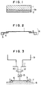
- Fig. 1 is a schematic cross-sectional view of a
plastic sheet for use in a plastic mask fabrication
method of the present invention.
- Fig. 2 is a schematic cross-sectional view of an
example of a plastic sheet body mounted before the
excimer laser abrasion thereof.
- Fig. 3 is a schematic cross-sectional view of a
plastic sheet which is abraded by an excimer laser
abrasion apparatus.
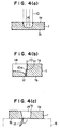
- Figs. 4(a) to 4(c) are schematic cross-sectional
views of a through-hole during the formation thereof in a
plastic sheet, showing a mechanism for the formation of a
remaining thin film in the through-hole during the
fabrication of a plastic mask.
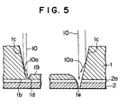
- Fig. 5 is a schematic cross-sectional view of a
bottom portion of a through-hole which is about to be
completely formed in a plastic sheet during the
fabrication of a plastic mask.
- Figs. 6(a) to 6(c) are schematic cross-sectional
views of a through-hole during the formation thereof in a
plastic sheet, showing a mechanism for the formation of a
non-clear-cut edge in the through-hole during the
fabrication of a plastic mask.
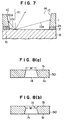
- Fig. 7 is a schematic cross-sectional view of a
through-hole which passes through both a plastic sheet
and a polymer film by excimer laser abrasion during the
fabrication of a plastic mask.
- Fig. 8(a) is a schematic cross-sectional view of a
through-hole free from a non-clear-cut edge.
- Fig. 8(b) is a schematic cross-sectional view of a
through-hole free with a non-clear-cut edge.
- Figs. 9(a) to 9(c) schematically show the steps of
the filling of a through-hole free from a non-clear-cut
edge in a fine pattern of through-holes with a paste in a
plastic fabrication method of the present invention.
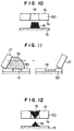
- Fig. 10 is a schematic cross-sectional view of a
through-hole through which a paste passes to form a
through-hole pattern on a printing material.
- Fig. 11 schematically shows the mechanism of
insufficient filling of a paste in a through-hole with a
non-clear-cut edge in a plastic mask.
- Fig. 12 schematically shows the formation of a paste
pattern with a non-printed portion on a printing material
by a through-hole with a non-clear-cut edge, with the
paste being caught by the upper end portion of the
through-hole, and with poor paste-passing performance
thereof.
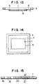
- Fig. 13 is a schematic cross-sectional view of a
plastic mask provided with an electroconductive layer of
the present invention, showing the entire structure
thereof.
- Fig. 14 is a schematic plan view of the plastic mask
in Fig. 13, showing the entire structure thereof.
- Fig. 15 is a schematic enlarged partial sectional
view of a first example of a plastic mask provided with
an electroconductive layer of the present invention.
- Fig. 16 is a schematic diagram in explanation of a
method of paste printing by use of the first example of
the plastic mask provided with an electroconductive
layer.
- Fig. 17 is a schematic diagram in explanation of the
peeling charges generated between a plastic mask and a
print-circuit board.
- Fig. 18 is a schematic cross-sectional view of a
plastic mask placed on a print-circuit board for
explanation of the close contact state thereof.
- Fig. 19 is a schematic partial enlarged cross-sectional
view of a second example of the plastic mask
provided with an electroconductive layer.
- Fig. 20 is a schematic diagram in explanation of a
method of paste printing by use of the second example of
the plastic mask provided with an electroconductive
layer.
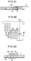
- Fig. 21 is a schematic enlarged partial sectional
view of a third example of a plastic mask provided with
an electroconductive layer of the present invention.
- Fig. 22 is a schematic partial enlarged view of a
penetrating opening containing area which comprises micro
slit-shaped through-holes in a first example of a plastic
mask comprising through-holes provided with reinforcement
portions.
- Fig. 23 is a cross-sectional view of the plastic
mask taken on line A - A' of Fig. 22.
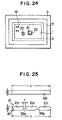
- Fig. 24 is a plan view of the first example of the
plastic mask comprising through-holes provided with
reinforcement portions, showing the entire structure
thereof.
- Fig. 25 is a diagram in explanation of the formation
of the reinforcement portions for the through-holes in
the plastic mask in Fig. 24.
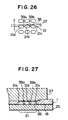
- Fig. 26 schematically shows a printing method for
printing a solder paste by use of the first example of
the plastic mask comprising through-holes provided with
reinforcement portions of the plastic mask, viewed from
the above.
- Fig. 27 shows the printing method shown in Fig. 26,
viewed from behind a squeegee.
- Fig. 28 is a schematic partial enlarged plan view of
a second example of the plastic mask of the present
invention, which has reinforcement portions for slit-shaped
through-holes thereof.
- Figs. 29(a) to 29(c) are schematic diagrams in
explanation of the reinforcement effect of the
reinforcement portions for slit-shaped through-holes.
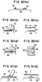
- Figs. 30(a) to 30(e) are schematic diagrams in
explanation of the effects of a foreign material or the
like placed on a pad on a metal mask for paste printing.
- Figs. 31(a) and 31(b) are schematic diagrams in
explanation of the state of a plastic mask affected by a
foreign material or the like on a pad.
- Fig. 32 is a schematic front cross-sectional view of
an urethane squeegee during the printing at a half-etching
portion.
- Fig. 33 is a schematic side cross-sectional view of
the urethane squeegee during the printing at the half-etching
portion in Fig. 32.
- Fig. 34 is a schematic side cross-sectional view of
a metal squeegee during the printing at a half-etching
portion.
- Fig. 35 is a schematic side cross-sectional view of
a printed solder paster when a solder paste remains on
the upper surface of a half-etching portion.
- Fig. 36 is a schematic plan view of an example of a
slit-shaped through-hole.
- Fig. 37 is a schematic side view of the ribs of
slit-shaped holes in explanation of the mechanism of the
bending of the ribs.
- Fig. 38 is a schematic plan view of the ribs of
slit-shaped holes in explanation of the mechanism of the
bending of the ribs.
-
-
As mentioned previously, a method of fabricating a
plastic mask for paste printing of the present invention
is a plastic mask fabricating method with a plastic sheet
being irradiated with an excimer laser beam for forming
at least one penetrating opening containing area
comprising at least one through-hole in the plastic
sheet, comprising the steps of (1) bringing a polymer
film capable of absorbing at least part of the excimer
laser beam into close contact with a back surface of the
plastic sheet which is opposite to an excimer laser beam
irradiation side thereof which is to be irradiated with
the excimer laser beam; (2) forming at least one
penetrating opening containing area comprising at least
one through-hole in the plastic sheet by irradiating the
excimer laser beam irradiation side thereof with the
excimer laser beam; and (3) removing the polymer film
from the plastic sheet after the formation of the
penetrating opening containing area.
-
According to the above plastic mask fabrication
method, since the polymer film is in close contact with
the back surface of the plastic sheet which is opposite
to the excimer laser beam irradiation side thereof, a
thin film which may remain at the bottom of each through-hole
to be made by excimer laser cannot come to the back
side of the plastic sheet, so that the thin film, if any,
is irradiated with excimer laser beams, until the
through-hole is completely made, and eventually no thin
film remains.
-
Even if a thin film remains at the bottom of the
through-hole for some reason, the thin film is removed
when the polymer film is peeled away from the plastic
sheet.
-
Furthermore, after the formation of the through-holes,
the excimer laser beam passes through the polymer
film which absorbs part of the laser beam, and therefore
is attenuated, but reaches the working table. Part of
the laser beam is reflected by the surface of the working
table. The reflected excimer laser beam is again
absorbed by the polymer film and attenuated, so that the
lower edge portions of the through-holes near the working
table are no longer abraded by the reflected excimer
laser beam and therefore, the formation of the through-holes
with non-clear-cut edges can be effectively
prevented.
-
As mentioned previously, the presence of the
remaining thin film at the bottom of the through-holes
and the through-holes with non-clear-cut edges cause
improper filling of the paste and unsmooth passing of the
paste through the through-holes, when paste printing is
performed by use of a squeegee which comes into contact
with the plastic mask. However, by disposing the polymer
film in close contact with the back surface of the
plastic sheet, the formation of the through-holes, and
the paste-filling performance and paste-passing
performance thereof can be significantly improved.
-
In the above-mentioned plastic mask fabrication
method, the polymer film may be releasably stuck on the
back surface of the plastic sheet opposite to the excimer
laser beam irradiation side thereof. When the polymer
film is releasably stuck on the back side of the plastic
sheet, the close contact of the polymer film with the
plastic sheet, and the removal of the polymer film from
the plastic sheet can be easily performed.
-
Another plastic mask for paste printing of the
present invention comprises a plastic sheet comprising at
least one penetrating opening containing area which
comprises at least one through-hole therein, the
penetrating opening containing area being formed by the
plastic sheet being irradiated with an excimer laser
beam, with the depth of each of the through-holes of the
penetrating opening containing area measured from the top
surface of the plastic mask to the narrowest portion of
each of the through-holes in the penetrating opening
containing area being 10 µm or less.
-
No remaining thin films are formed during the
fabrication of this plastic mask, and since the depth of
each of the through-holes measured from the top surface
of the plastic mask to the narrowest portion of each of
the through-holes is 10 µm or less, when paste printing
is performed by use of this plastic mask with a paste
which contains solder solid particles, for example,
solder solid particles mostly with a minimum diameter of
20 µm in a solder paste, the paste spread on the surface
of the plastic mask can be sharply scraped off the
uppermost level of each through-hole, and the through-holes
are completely filled with the paste, so that high
quality paste printing with high precision can be
performed without improper spreading or non-printing
portions in the same through-hole pattern in the
penetrating opening containing area of the plastic mask.
-
The above-mentioned plastic mask of the present
invention may have a thickness of 10 to 500 µm and a
modulus of bending elasticity of 20 to 500 Kgf·mm-2.
-
When paste printing is performed by use of this
plastic mask, in particular, when the paste is spread on
the plastic mask with the plastic mask being brought into
close contact with a printing material by a squeegee
which applies pressure to the upper surface of the
plastic mask downward, even if the printing material has
convex portions on the surface thereof, the gaps between
the plastic mask and the printing material can be
eliminated or minimized, whereby the paste can be
prevented from entering the gaps between the plastic mask
and the printing material when the through-holes are
filled with the paste. As a result, improper spreading
of the printed paste pattern can be prevented or
minimized. Furthermore, the smearing of the back side of
the plastic mask with the spread paste can be minimized
and the paste printing can be repeated a greater number
of times than by the conventional metal masks, without
wiping the paste off the back side of the plastic mask or
cleaning the back side of the plastic mask.
-
A paste printing method of the present invention
comprises the steps of (1) bringing a paste printing mask
comprising at least one penetrating opening containing
area which comprises at least one through-hole into close
contact with a printing material; (2) filling each of the
through-holes in the penetrating opening containing area
with a paste comprising solid particles by spreading and
pressing the paste on the paste printing mask; and (3)
removing the paste printing mask from the printing
material, thereby forming on the printing material a
paste pattern in the same pattern as that of the through-holes
in the penetrating opening containing area, wherein
as the paste printing mask, there is employed a plastic
mask for paste printing provided with a penetrating
opening containing area, the penetrating opening
containing area being formed in a plastic sheet so as to
include at least one through-hole by excimer laser beam
abrasion, with the depth of each of the through-holes of
the penetrating opening containing area measured from the
top surface of the plastic mask to the narrowest portion
of each of the through-holes in the penetrating opening
containing area being 1/2 or less the particle size of
the solid particles contained in the paste.
-
According to this paste printing method of the
present invention, the depth of each of the through-holes
measured from the top surface of the plastic mask to the
narrowest portion of each of the through-holes being 1/2
or less the particle size of the solid particles
contained in the paste, so that the paste can be smoothly
spread onto the surface of the plastic mask and sharply
scraped off the uppermost level of each through-hole, and
the lower portion of the spread paste is easily scraped
off by the upper end portions of the through-holes in the
front and the through-holes can be completely filled with
the scraped paste and the filled paste can smoothly pass
through the through-holes, so that high quality paste
printing with high precision can be performed in the same
through-hole pattern in the penetrating opening
containing area of the plastic mask.
-
In the above-mentioned paste printing method, the
plastic mask for paste printing may have a thickness of
10 to 500 µm and a modulus of bending elasticity of 20 to
500 Kgf·mm-2.
-
Because of the above-mentioned combined conditions
for the thickness and modulus of bending elasticity of
the plastic mask, when paste printing is performed by use
of this plastic mask, in particular, when the paste is
spread on the plastic mask with the plastic mask being
brought into close contact with a printing material by a
squeegee which applies pressure to the upper surface of
the plastic mask downward, even if the printing material
has convex portions on the surface thereof, the gaps
between the plastic mask and the printing material can be
eliminated or minimized, whereby the paste can be
prevented from entering the gaps between the plastic mask
and the printing material when the through-holes are
filled with the paste. As a result, improper spreading
of the printed paste pattern can be prevented or
minimized. Furthermore, the smearing of the back side of
the plastic mask with the spread paste can be minimized
and the paste printing can be repeated a greater number
of times than by the conventional metal masks, without
wiping the paste off the back side of the plastic mask or
cleaning the back side of the plastic mask.
-
A further plastic mask for paste printing of the
present invention comprises a plastic sheet with a
penetrating opening containing area comprising at least
one through-hole; and an electroconductive layer formed
on at least one of the opposite upper and lower surfaces
of the plastic sheet.
-
In the above plastic mask, since the electroconductive
layer is provided on at least one of the
opposite surfaces of the plastic mask, the electric
charges generated by the friction between a plastic
squeegee such as an urethane squeegee and the surface of
the plastic mask are grounded through the electroconductive
layer and dissipate. Therefore, it never
occurs that electric charges are built up on the surface
of the plastic mask. Therefore, there is not the risk
that mounted electronic parts are subjected to electrostatic
destruction by the electric charges. Therefore,
precise and high quality paste printing can be performed
for electronic parts and boards which are vulnerable to
electrostatic charges by making best use of the
advantages of the plastic mask.
-
Furthermore, by the provision of the electroconductive
layer on the plastic sheet, the abrasion
resistance of the plastic sheet can be improved, so that
the life of the plastic mask can be significantly
extended.
-
In the above-mentioned plastic mask, the electroconductive
layer may be provided on only one of the
opposite surfaces of the plastic sheet with which surface
a printing material is to come into contact.
-
In this plastic mask, the electroconductive layer is
provided on only the surface of the plastic sheet with
which surface a printing material is to come into
contact, so that paste printing can be performed by use
of an electroconductive paste, with the electroconductive
layer of the plastic mask being grounded, whereby the
electrostatic charges generated on the surface of the
plastic mask during paste printing can be caused to
dissipate to the lower electroconductive layer through
the electroconductive paste.
-
Further, in the above-mentioned plastic mask, the
electroconductive layer may be provided on each of both
upper and lower surfaces of the plastic sheet in such a
manner that the two electroconductive layers are
electrically connected with each other.
-
In this plastic mask, since the electroconductive
layer is provided on both sides of the plastic sheet in
such a manner that the two electroconductive layers are
electrically connected with each other, paste printing
can be performed with the lower electroconductive layer
of the plastic mask being grounded, so that the electrostatic
charges generated on the plastic mask can be led
to the lower electroconductive layer through the upper
electroconductive layer. Therefore, even when paste
printing is performed by use of an insulating paste, the
electrostatic charges can be caused to dissipate. As a
matter of course, an electroconductive paste can also be
employed.
-
In the above-mentioned plastic mask, the two
electroconductive layers may be electrically connected
with each other through an electroconductive adhesive
agent.
-
In this plastic mask, since the structure thereof
can be more simplified since the two electroconductive
layers are electrically connected with each other through
an electroconductive adhesive agent.
-
Furthermore, in the above-mentioned plastic mask,
the electroconductive layer may be an abrasion resistant
electroconductive layer, and as the electroconductive
layer, any of chromium, nickel, aluminum, stainless steel
and titanium coating electroconductive layers can be
employed, although of such coating electroconductive
layers, a titanium electroconductive layer is preferable
in the present invention.
-
In this plastic mask, since the electroconductive
layer is abrasion resistant, the life of the plastic mask
can be prolonged.
-
A further paste printing method of the present
invention comprises the steps of (1) bringing a paste
printing mask provided with a penetrating opening
containing area comprising at least one through-hole
formed in a predetermined pattern into close contact with
a printing material; (2) filling each of the through-holes
in the penetrating opening containing area with a
paste by spreading and pressing the paste on the paste
printing mask, and (3) removing the paste printing mask
from the printing material, thereby forming on the
printing material a paste pattern in the same pattern as
that of the penetrating opening containing area, wherein
as the paste printing mask, there is employed a plastic
mask for paste printing, which comprises (a) a plastic
sheet with a penetrating opening containing area
comprising at least one through-hole in a predetermined
pattern, and (b) an electroconductive layer which is
formed on at least one of the opposite upper and lower
surfaces of the plastic sheet and electrically grounded.
-
In the above paste printing method, the electroconductive
layer may be provided on only the surface of
the plastic sheet with which a printing material is to
come into contact.
-
Further, the electroconductive layer may be provided
on each of both upper and lower sides of the plastic
sheet in such a manner that the two electroconductive
layers are electrically connected with each other.
-
The above-mentioned two electroconductive layers may
be electrically connected with each other through an
electroconductive adhesive agent.
-
In the above paste printing method, the electroconductive
layer may be an abrasion resistant electroconductive
layer.
-
Furthermore, in the above paste printing method,
each of the electroconductive layers may be an abrasion
resistant electroconductive layer.
-
Furthermore, in the above paste printing method, as
the electroconductive layer of the printing mask, any of
chromium, nickel, aluminum, stainless steel and titanium
coating electroconductive layers may be employed. Of
these coating electroconductive layers, a titanium
electroconductive layer is preferable in the present
invention.
-
According to the above-mentioned paste printing
methods of the present invention, since the electroconductive
layer is grounded, paste printing can be
performed while dissipating the triboelectric charges
which are generated during the paste printing, and the
electrostatic charges which are generated when the
plastic mask is peeled away from the printing material.
Thus, paste printing can be carried out under the
conditions free from the electrostatic charges. Furthermore,
the abrasion of the plastic mask, which may be
caused by the repetition of the paste printing, can be
prevented.
-
A further plastic mask of the present invention
comprises a plastic sheet comprising at least one
penetrating opening containing area which comprises a
plurality of slit-shaped through-holes which are formed
in a head-to-tail arrangement with a joint reinforcement
portion being provided between each of the slit-shaped
through-holes in the head-to-tail arrangement. The slit-shaped
through-holes are arranged in a plurality of rows
with the longer side of each of the slit-shaped through-holes
being positioned side by side.
-
In the above-mentioned plastic mask, the thrusting
of a squeegee into the inside of each slit-shaped
through-hole is minimized since each joint reinforcement
portion serves as a support for preventing the thrusting
of the joint reinforcement portion into the slit-shaped
through-holes. Even if the tip of the squeegee enters
the slit-shaped through-holes and pulls the portions
between the longer sides of the slit-shaped through-holes,
which are hereinafter referred to as the ribs of
the slit-shaped through-holes, the reinforcement portions
can minimize the bending of the ribs. Thus, improper
paste printing which might be caused by the bending of
the ribs can be prevented. Furthermore, since the
bending of the ribs can be minimized, the breaking of the
ribs and base portions thereof by the fatigue thereof
caused by the repeated bending thereof can also be
minimized, so that the life of the printing mask can be
prolonged.
-
In the above plastic mask, the ends of each of the
slit-shaped through-holes may be rounded. When the ends
of each of the slit-shaped through-holes are rounded,
even if the tip of the squeegee enters the slit-shaped
through-holes, the concentration of the stress on the
ends of each of the slit-shaped through-holes does not
take place, so that the fatigue breaking of the ribs can
be more effectively prevented.
-
In the above plastic mask, the rows of the slit-shaped
through-holes may be arranged in parallel to each
other, and the joint reinforcement portions may be
disposed in line at a predetermined angle with respect to
the parallel rows of the slit-shaped through-holes, for
example, with right angles, with respect to the moving
direction of the squeegee.
-
In this plastic mask, since the joint reinforcement
portions are disposed in line, for instance, with respect
to the moving direction of the squeegee, so that the
bending of the ribs can be further reduced and therefore
the ribs are protected against the pulling force applied
thereto by the squeegee by a series of the joint
reinforcement portions which are connected in line,
whereby excellent paste printing can be carried out.
-
Still another paste printing method of the present
invention comprises the steps of (1) bringing a paste
printing mask comprising a penetrating opening containing
area which comprises a plurality of slit-shaped through-holes
formed in a predetermined pattern into close
contact with a printing material; (2) filling each of the
through-holes in the penetrating opening containing area
with a paste by spreading and pressing the paste on the
paste printing mask, and (3) removing the paste printing
mask from the printing material, thereby forming on the
printing material a paste pattern in the same pattern as
that of the slit-shaped through-holes in the penetrating
opening containing area, wherein as the paste printing
mask there is employed a plastic sheet comprising at
least one penetrating opening containing area comprising
a plurality of slit-shaped through-holes which are formed
in a head-to-tail arrangement with a joint reinforcement
portion between each of the slit-shaped through-holes in
the head-to-tail arrangement in a plurality of rows with
the longer side of each of the slit-shaped through-holes
being positioned side by side.
-
In the above paste printing method, the edges of
each of the slit-shaped through-holes are preferably
rounded.
-
Furthermore, in the above paste printing method, it
is preferable that the joint reinforcement portions be
arranged in line at a predetermined angle with respect to
each row of the slit-shaped through-holes.
-
In the above-mentioned paste printing method, the
binding of the ribs of the slit-shaped through-holes is
minimized and therefore the fatigue breaking of the ribs
can be prevented, whereby high quality paste printing can
be carried out.
-
According to the above paste printing method, the
employed plastic mask is softer and more flexible than
the metal masks and therefore can flexibly follow up any
convex and concave portions on a printing surface to
attain close contact therewith without any gap or with a
minimum gap between the mask and the printing surface.
-
Furthermore, since the plastic mask is flexible,
when it is peeled away from the printing surface, the
plastic mask can be immediately returned to its original
flat shape. In other words, in the plastic mask, there
occurs no irreversible deformation as in the metal mask
such as a nickel sheet formed by plating, when the mask
is brought into close contact with a printing surface
with convex and concave portions thereon.
-
Further, even if a small amount of the paste gets
into the back side of the plastic mask from the through-holes,
and the solid particles contained in the paste are
depressed between the printing mask and the printing
surface, such depressed solid particles hardly adhere to
the back side of the plastic mask since the surface of
the plastic mask is extremely smooth and therefore the
gap between the plastic mask and the printing surface, if
any, is not increased by such solid particles.
Therefore, on the printing surface, there can be formed a
paste pattern which accurately corresponds to the pattern
of the through-holes formed in the mask and is free from
any spreading of the paste, whereby highly precise, high
quality paste printing can be performed.
-
Furthermore, the paste printing can be repeated a
number of times, without wiping the paste off the back
side of the plastic mask or cleaning the back side of the
plastic mask.
-
Other features of this invention will become
apparent in the course of the following description of
exemplary embodiments, which are given for illustration
of the invention and are not intended to be limiting
thereof.
Example [Method of Fabricating Plastic Mask]
-
As illustrated in Fig. 1, a polymer film 2 capable
of absorbing part of an excimer laser beam was releasably
stuck on a plastic sheet 1 through an adhesive agent 2a.
-
A polyimide film with a thickness of 125 µm was
employed as the plastic sheet 1; and a polyester film
with a thickness of 25 µm was employed as the polymer
film 2 capable of absorbing part of an excimer laser
beam. To this polyester film, a silicone adhesive agent
was applied as the adhesive agent 2a. Thus, a layered
material composed of the polyester film and the polyimide
film was prepared.
-
As illustrated in Fig. 2, a polyester mesh screen 4
stuck on a mask frame 3, there was stuck by use of an
adhesive agent 5 the thus prepared layered material cut
with an appropriate size in such a posture that the
polyester film came downward and the polyimide film
serving as the plastic sheet 1 came upward.
-
After the adhesive agent 5 was cured, a plastic
sheet body 6 to be subjected to excimer laser abrasion
was prepared by cutting off an inside portion of the
polyester mesh screen with respect to the applied
adhesive agent 5.
-
As illustrated in Fig. 3, the plastic sheet body 6
was set on a working XY table 8 in such a manner that the
polyester film of the plastic sheet body 6 was brought
into close contact with the surface of the working XY
table 8 by fixing the mask frame 3 to the working XY
table 8 by a clump 7, whereby accurate registration of
the plastic sheet body 6 at an excimer laser beam
irradiation position was carried out by appropriately
moving the working XY table 8.
-
The polyimide film of the plastic sheet 1 was
irradiated with an excimer laser beam 10 which was output
from an excimer laser beam generator 9 situated above the
plastic sheet body 6, through a light-shielding aperture
mask 11 with a pattern of through-holes of a plastic
mask, a condenser lens 12 and then a lens 13.
-
The above excimer laser beam was generated with a
wavelength of 248 nm by krypton-fluorine gas and at a
pulse frequency of 200 Hz/sec, and the surface of the
polyimide film was irradiated with this excimer laser
beam at an energy density of 1.7 Joule/cm2 through the
condenser lens 12 and the lens 13, whereby the abrasion
was carried out at an abrasion speed of about 0.5
µm/pulse for 1.25 seconds.
-
The plastic sheet body 6 was then detached from the
working XY table 8, and the polyester film which was
applied to the polyimide film was removed together with
the silicone adhesive agent, whereby a plastic mask with
a pattern of through-holes was obtained.
-
The thus obtained plastic mask was free from
remaining films and non-clear-cut edges in the through-holes.
-
A minimum pitch of the pattern obtained by this
method was 0.1 mm.
-
The thus fabricated plastic mask with a pattern with
a pitch of 0.4 mm was brought into close contact with a
print-circuit board made of glass epoxy. A solder paste
containing spherical solid particles with a particle size
of 20 µm to 44 µm was spread on the plastic mask by use
of an urethane squeegee, and the pattern-shaped through-holes
were filled with the solder paste.
-
The plastic mask was then removed from the print-circuit
board, whereby a paste pattern of the through-holes
was formed on the print-circuit board.
-
The paste-filling performance and paste-passing
performance of the through-holes of the plastic mask were
excellent, so that high quality paste printing with high
precision of the pattern free from non-printing portions
and improper spreading was carried out on the print-circuit
board.
-
The back side of the plastic mask was not
substantially smeared with the paste, so that it was
possible to repeat the paste printing with high quality
and high precision more than 100 times without wiping the
paste and also without cleaning the back side of the
plastic mask. In contrast, even in the case of an
additive mask, which is considered to be best of the
metal masks in terms of the printing quality, the paste
must be wiped from the back side of the mask at every
several printings, and the back side of the mask must be
cleaned at several ten times.
-
The excimer laser which is employed in the fabrication
of the plastic mask of the present invention can
perform the abrasion working, or non-heating or photo-chemical
working which cannot be performed by other
lasers such as CO2 or YAG laser. The excimer laser is
particularly suitable for precise working of organic
polymers.
-
The CO2 or YAG laser working is thermal working which
mainly utilizes laser beams with wavelengths in infrared
region. In contrast to this, the abrasion working or
non-heating working conducted by use of the excimer laser
is carried out by utilizing the laser beams in ultra-violet
region. When an organic polymer is irradiated
with the excimer laser beam, the molecules of the organic
polymer absorb the energy of the excimer laser beam and
are excited to the extent that the bonds of the molecules
are cleaved. As a result, the organic polymer is
decomposed to the constituents molecules and scattered in
the form of a gas.
-
This decomposition process proceeds within several
10 ns, so that although the molecules are heated to about
6000°K at the time of the cleavage and scattered at an
initial speed of as great as 5000 to 10000 m/sec, there
is not enough time for the heated molecules to heat any
materials adjacent to the heated molecules. Therefore
in the abrasion working by the excimer laser, problems
such as denaturation or modification which may be caused
by the application of heat are never caused in the
portions adjacent to the portion worked by the excimer
laser beam, and the worked surface is extremely smooth
and clean.
-
Furthermore, in the case of CO2 or YAG laser working,
a laser beam which is narrowed down is applied to a
working subject. In sharp contrast to this, the excimer
laser beam has a larger beam projection cross-section.
For instance, some excimer laser beam has a beam
projection cross-section with a major axis of about 20 mm
and a minor axis of 8 to 9 mm. Thus, a larger area can
be worked at a time by the excimer laser abrasion than by
the CO2 or YAG laser working.
-
When an excimer laser beam is used in practice,
there may be the case where the output energy thereof is
insufficient for performing actual abrasion. In such a
case, the excimer laser beam is condensed. When
condensed, the working area may be reduced to less than
1/2, but the excimer laser abrasion still has the
advantage over other working methods that planar working
is possible.
-
By utilizing this feature of the excimer laser
abrasion, when a plastic sheet is irradiated with an
excimer laser beam through a light-shielding aperture
mask with a pattern of through-holes through which the
excimer laser beam can pass, a thin concave portion or
through-holes can be formed in a similar shape or pattern
to that of the pattern in the light-shielding aperture
mask can be formed in the plastic sheet. Thus, there can
be prepared a printing plastic mask with excellent
smoothness of the inner walls of the through-holes.
-
By this excimer laser abrasion, a plastic mask with
a pattern of through-holes with a pitch of as small as
0.1 mm can be fabricated.
-
Furthermore, according to the plastic fabrication
method of the present invention, a polymer film which is
capable of absorbing at least part of the excimer laser
beam is disposed in close contact with the back surface
of the plastic sheet which is opposite to the excimer
laser beam irradiation side thereof; the plastic sheet is
irradiated with the excimer laser beam to form through-holes
in the plastic sheet; and the polymer film is
removed from the plastic sheet, whereby there can be
formed a plastic mask which is free from thin films which
may remain at the bottom of each through-hole, the so-called
"remaining thin films" and free from non-clear-cut
edges in the through-hole, the so-called "non-clear-cut
edges", or there can be formed a plastic mask with
minimized formation of such "remaining thin film" and
"non-clear-cut edges".
-
In particular, a plastic mask with through-holes
with a minimum pitch of 0.1 mm to about 0.01 mm, free
from the "remaining thin film" and "non-clear-cut edges"
or with minimized formation thereof, can be fabricated
according to the present invention.
-
The above-mentioned minimum pitch obtained by the
plastic mask of the present invention is in the range of
1/4 to 1/3 the minimum pitch obtained by the conventional
metal mask, which is in the range of 0.4 mm to 0.3 mm.
-
With respect to the non-formation of the "remaining
thin film" in the plastic mask fabrication method of the
present invention, the following mechanism can be
considered:
-
Figs. 4(a) to 4(c) show a mechanism for the
formation of the "remaining thin film" in a plastic mask
fabrication method. Fig. 4(a) shows the formation of
part of a through-hole in the plastic sheet. Fig. 4(b)
is an enlarged partial view of a gouged portion in the
bored through-hole. Fig. 4(c) shows a remaining thin
film.
-
As shown in Fig. 4(a), an excimer laser beam
irradiation surface 1a of a plastic sheet 1 is irradiated
with an excimer layer beam 10, part of a through-hole 14
with a tapered inner wall to the bottom as illustrated in
Fig. 4(a) is formed. In the course of the formation of
the through-hole 14, a laser beam reflected by the
tapered inner wall 1c, which is hereinafter referred to
as the reflected laser beam 10a, proceeds the abrasion of
a corner portion 1d to form a gouged portion therein.
-
When the abrasion of the corner portion 1d does not
proceed uniformly, a thin film 1f is formed and turned to
the back side 1b of the plastic sheet 1 on a portion
which is slightly connected to the plastic sheet 1 and
serves as a pivot for the turning of the thin film 1f, in
a portion of the plastic sheet 1 which is not in close
contact with a working table 8, by the repulsion of the
abrasion. The thin film 1f is then no longer irradiated
with the excimer laser beam 10, so that the thin film 1f
remains at the bottom of the through-hole 14.
-
In sharp contrast to this, according to the printing
plastic mask fabrication method of the present invention,
a polymer film is in close contact with the back side of
the plastic sheet which is opposite to the excimer laser
beam irradiation surface thereof, so that the thin film
at the bottom of the through-hole which is about to be
completely formed by the excimer laser beam abrasion is
not turned to the back side of the plastic sheet and
remains until the through-hole is completely formed, and
such a thin film does not remain. Even if some thin film
remains on the polymer film which is in close contact
with the plastic sheet, since the polymer film is removed
after the formation of the through-hole, no thin film
remains on the printing plastic mask.
-
Fig. 5 schematically shows the state of the bottom
of a through-hole which is about to be completely formed
by the excimer laser beam by the plastic mask fabrication
method of the present invention. As shown in Fig. 5, a
gouged portion is formed at a corner portion 1d between a
bottom surface 1g and an inner wall 1c of the through-hole
since the abrasion is significantly promoted because
of an increased energy density due to the overlapping of
a reflection laser beam 1a reflected by the tapered
surface of an inner wall 4 and a direct laser beam 10
which is directly projected from right above.
-
On the other hand, at the other corner 1e, an inner
wall 1c is cut off the bottom surface 1g. When the
number of the cut-off corners is increased and the number
of connected portions is decreased, the thin film at the
bottom of the through-hole receives such a force that
makes the thin film turn pivotally on a singly connected
portion at the corner portion 1d toward the back side 1b
of the plastic sheet by the repulsion force which is
generated by the molecules which are scattered in the
state of a plasma at an initial speed of 5000 to 10,000
m/sec by the excimer laser beam abrasion. However, the
thin film cannot is not moved to the back side 1b of the
plastic sheet because it is stopped by the polymer film 2
disposed at the lower side of the bottom portion 1g
through an adhesive agent 2a, which polymer film 2 is
capable of absorbing at least part of the excimer laser
beam. As a result, the thin film is irradiated by the
excimer laser beam until the through-hole is completely
made, so that the thin film does not remain.
-
According to the plastic mask fabrication method of
the present invention, there are formed no "non-clear-cut
edges" in the through-holes or the formation of the "non-clear-cut
edges" is minimized. It is considered that
this is accomplished by the following mechanism:
-
Figs. 6(a) to 6(c) show the mechanism for the
formation of the "non-clear-cut edges" in the through-holes.
-
Fig. 6(a) shows the state of the formation of part
of a through-hole. Fig. 6(b) is an enlarged view of part
of a through-hole immediately after the formation
thereof. Fig. 6(c) is an enlarged view of a non-clear-cut
edge formed in the through-hole.
-
As shown in Fig. 6(a), a through-hole 14 is being
formed as the plastic sheet 1 in close contact with the
working table 8 is irradiated with the excimer laser beam
10.
-
As shown in Fig. 6(b), after the formation of the
through-hole 14, the applied excimer laser beam 10 is
scattered by the surface of the working table 8 as shown
by 10b.
-
As shown in Fig. 6(c), the lower end portion of the
through-hole 14 formed in the plastic sheet 1 is abraded
by the excimer laser beam 10b scattered near the lower
end portion of the through-hole 14, so that the edge of
the through-hole 14 is rounded and the "non-clear-cut
edge" 1h is formed at the lower end portion of the
through-hole 14.
-
In contrast to this, according to the plastic mask
fabrication method of the present invention, the polymer
film is applied to the back side of the plastic sheet
opposite to the excimer laser beam irradiation surface
thereof, so that after the formation of the through-hole,
the excimer laser beam is attenuated, but reaches the
working table. Part of the excimer laser beam is
reflected by the surface of the working table and
absorbed by the polymer film, so that the lower end
portion of the through-hole is no longer abraded by the
reflected excimer laser beam. Thus, the formation of the
"non-clear-cut edge" in the through-hole can be
prevented.
-
When a through-hole which passes through the plastic
sheet and the polymer film is formed, the excimer laser
beam is not attenuated unit it reaches the working table.
However, the excimer laser beam is reflected by the
surface of the working table and then absorbed by the
polymer film which is in close contact with the plastic
sheet at the edge portion of the through-hole, so that
the reflected excimer laser beam is attenuated. Thus,
the lower end portion of the through-hole is no longer
abraded by the reflected excimer laser beam, and
therefore the formation of the "non-clear-cut edge" in
the through-hole can be prevented. In this case, it may
occur that the polymer film which is in close contact
with the plastic sheet is abraded at the lower portion of
the through-hole and a non-clear-cut edge is formed at
the polymer film. However, since the polymer film is
removed from the plastic sheet after the formation of the
through-hole, such abrasion in the polymer film has no
adverse effects on the paste printing by use of the
plastic mask thus prepared.
-
Furthermore, in the case where there is formed a
through-hole which passes not only through the plastic
sheet, but also through the polymer film, the excimer
laser beam reflected by the surface of the working table
reaches the inner wall of the through-hole, but the inner
wall is rarely abraded by the reflected excimer laser
beam. It is considered that this may be because the
intensity of the received excimer laser beam per unit
area on the inner wall of the through-hole is
significantly decreased by (1) the attenuation of the
excimer laser beam reflected by the surface of the
working table, (2) the decrease of the energy density
thereof by the scattering of the laser beam by the
reflection, and (3) the slanting projection of the laser
beam from the lower position onto the inner wall of the
through-hole.
-
Fig. 7 schematically shows a through-hole which
passes not only through the plastic sheet, but also
through the polymer film, formed by the plastic mask
fabrication method of the present invention.
-
When the excimer laser beam abrasion proceeds, the
plastic sheet 1, the adhesive agent 2a and the polymer
film 2 in the respective abraded portions are scattered
and disappear. The excimer laser beam 10 reaches the
working table 8, and is partly absorbed by the working
table 8 and reflected by the working table 8, whereby
scattered beams 10c, 10d, 10e and the like are formed.
-
The scattered beams 10d and 10e strike at the inner
wall 1c of the through-hole formed in the plastic sheet
1. However, the energy density of the scattered beam 10d
per unit area of the inner wall 1c is significantly
lowered because of the attenuation of the energy density
thereof by the scattering of the beam, and the slanted
projecting direction with respect to the inner wall 1c.
-
With respect to the scattered beam 10e, the slanted
projection angle with respect to the inner wall 1c is
smaller than that of the scattered beam 1d, but the
travelling distance up to the inner wall 1c is larger
than that of the scattered beam 1d, so that the
attenuation of the energy density of the scattered beam
10e is much larger than that of the scattered beam 10d.
-
Therefore, it is not considered that the inner wall
1c of the through-hole 14 is abraded by any of the
scattered beams 10d and 10e.
-
The scattered beam 10c reflected immediately near
the inner wall 1c of the through-hole 14 is small in the
scattering of the energy thereof, so that it is possible
that the lower tip portion of the polymer film 2 is
abraded by the scattered beam 10c. However, the polymer
film 2 is removed together with the adhesive agent 2a
after the formation of the through-hole, so that the
abrasion of the polymer film 2 does not have any adverse
effect on the paste printing by use of this plastic mask.
-
When paste printing is performed by use of the
plastic mask prepared by the plastic mask fabrication
method of the present invention, the plastic mask is used
upside down.
-
Therefore, when no "non-clear-cut edges" are formed
in the through-hole formed in the plastic sheet, the
narrowest opening portion of the through-hole comes to
the uppermost surface of the plastic mask when used in
practice for paste printing, and even if some "non-clear-cut
edges" are formed in the through-hole, the narrowest
opening portion of the through-hole comes near the
uppermost surface of the plastic mask when used in
practice.
-
Fig. 8(a) is a schematic cross sectional view of a
through-hole free from a non-clear-cut edge formed in a
plastic mask 50. As shown in Fig. 8(a), the narrowest
opening portion W is formed at the uppermost surface of
the plastic mask 50.
-
Fig. 8(b) is a schematic cross sectional view of a
through-hole with a non-clear-cut edge formed in a
plastic mask 50. As shown in Fig. 8(a), the narrowest
opening portion W is formed very close to the uppermost
surface of the plastic mask 50 at a depth H therefrom.
-
According to the plastic mask fabrication method of
the present invention, there can be fabricated a plastic
mask with through-holes free from the "remaining thin
films" and "non-clear-cut edges" or with minimized
formation thereof, with the depth of the through-holes
from the uppermost surface of the plastic mask to the
narrowest portion of the through-holes being 25 µm or
less, 20 µm or less, 15 µm or less, 10 µm or less, and 5
µm or less, if necessary.
-
Such a plastic mask for printing can be selectively
used in accordance with the fabrication efficiency and
the kind of a paste to be used in printing.
-
Plastic masks free from the "remaining thin films"
and "non-clear-cut edges", and plastic mask free from the
"remaining thin films" and a minimum depth from the
uppermost surface of the mask to the narrowest portion of
the through-holes are preferable for use since such
plastic masks can be used in any kinds of paste printing
for obtaining fine patterns free from non-printed
portions or improper spreading.
-
The inventor of the present invention has made
investigations about a paste printing method by use of
the thus fabricated plastic mask and discovered that in a
paste printing for printing a pattern of a paste
containing solid particles on a printing material by
bringing the plastic mask into close contact with the
printing material, spreading the paste on the plastic
mask to fill a pattern of through-holes formed in the
mask with the paste, removing an excessive paste from the
surface of the mask, and removing the mask from the
printing material, high quality paste printing can be
carried out, with excellent paste-filling performance and
paste-passing performance with respect to the through-holes,
when the depth from the uppermost surface of the
mask to the narrowest portion of each through-hole is not
more than 1/2 the particle size of the solid particles
contained in the paste.
-
It is considered that the above-mentioned excellent
paste-filling performance and paste-passing performance
can be attained by the following mechanism in this
printing method.
-
Figs. 9(a) to 9(c) schematically show the steps of
the filling of the paste in a through-hole free from
"non-clear-cut edge" in a pattern of fine through-holes
formed in a plastic mask fabricated by the plastic mask
fabrication method of the present invention.
-
Fig. 9(a) shows the step of the initiation of the
spreading of the paste. Fig. 9(b) shows the step of
scraping the spread paste. Fig. (c) shows the step of
filling the through-hole with the paste.
-
As shown in Fig. 9(a), when a paste 16 is spread by
a squeegee 17 on the surface of a plastic mask 50 which
is set in close contact with a printing material 19, the
paste 16 is moved along the surface of the plastic mask
50 as the paste 16 rolls and slips on the plastic mask
50.
-
The paste 16 then passes over the upper portion of a
through-hole 14, and the lower portion of the paste 16 is
then scraped by the front upper end 14a of the through-hole
14 as shown in Fig. 9(b). The scraped paste 16 is
then moved toward the squeegee 17 and the through-hole 14
is then filled with the successively scraped paste 16.
-
When the plastic mask with the through-holes being
thus filled with the paste 16 is removed from the
printing material 15, the paste 16 is caused to smoothly
pass through the through-hole 14, so that a pattern of
fine through-holes free from non-printed portions and
improper spreading is printed on the printing material
15.
-
Even if there is a slight non-clear-cut edge in the
through-hole 14, when the depth from the uppermost
surface of the plastic mask to the narrowest portion o f
the through-hole 14 is not more than 1/2 the particle
size of the solid particles contained in the paste, a
pattern of fine through-holes free from non-printed
portions and improper spreading can be printed on the
printing material 15, with excellent paste-filling
performance and paste-passing performance.
-
In contrast to this, when the depth from the
uppermost surface of the plastic mask to the narrowest
portion o f the through-hole 14 exceeds 1/2 the particle
size of the solid particles contained in the paste, it is
difficult for the lower portion of the paste 16 to be
scraped by the front upper end 14a of the through-hole 14
as shown in Fig. 11, so that the filling of the through-hole
14 with the paste becomes insufficient. Furthermore,
as shown in Fig. 12, when the plastic mask 50 is
removed from the printing material 15, part of the paste
16 is caught by the non-clear-cut edge of the upper
portion of the through-hole, so that the paste-passing
performance is degraded and a paste pattern with a non-printed
portion is printed on the printing material 15.
-
As the material for the plastic sheet for use in the
present invention, any organic polymers which permit
excimer laser beam abrasion can be employed. Even an
organic polymer for which excimer laser beam abrasion is
difficult or impossible to conduct, can also be subjected
to excimer laser beam abrasion by mixing therewith a
compound capable of absorbing excimer laser beam such as
finely-divided carbon particles and an ultraviolet
absorbing agent, or an organic polymer which can be
subjected to the excimer laser beam abrasion.
-
It is preferable that the plastic sheet for use in
the present invention have the properties that are
required for the plastic mask, namely, the following
properties: (1) chemical resistance, for example, against
the paste, solvents contained in the paste, and cleaning
agents employed after paste printing; (2) sufficient
abrasion resistance for use as a printing sheet; (3)
sufficient mechanical strength for attaining dimensional
stability when tension is applied when it is mounted on a
frame; and (4) low friction, and water repellency
suitable for attaining the previously mentioned excellent
paste-passing performance.
-
Specific examples of the plastic sheet for use in
the present invention are organic polymers for which the
excimer laser beam abrasion can be easily conducted, such
as polyimide, polyester, epoxy resin and polycarbonate;
and organic polymers for which the excimer laser beam
abrasion is difficult or impossible to conduct, such as
polyethylene, polypropylene, polyacetal and teflon.
-
The latter organic polymers can be used by mixing
therewith a compound capable of absorbing excimer laser
beam, or an organic polymer which can be subjected to the
excimer laser beam abrasion as mentioned previously.
-
It is preferable that the plastic sheet, or the
plastic mask of the present invention, have a thickness
in the range of about 10 µm to 500 µm; and that a plastic
mask for paste printing by use of a solder paste of the
present invention have a thickness in the range of about
100 µm to 200 µm.
-
It is also preferable that the plastic mask of the
present invention have a modulus of bending elasticity of
about 20 to 500 Kgf·mm-2. A plastic mask with a thickness
in the above-mentioned range and the above-mentioned
modulus of bending elasticity is capable of eliminating
or minimizing the gaps between the plastic mask and a
printing material when the plastic mask is brought into
close contact with the printing material even if the
printing material has some convex portions on the surface
thereof, whereby the entering of the paste the gaps
between the plastic mask and the printing material can be
prevented. As a result, a paste pattern free from
improper spread can be sharply formed. Furthermore,
since the back side of the plastic mask is not smeared or
hardly smeared with the plate, the plastic mask can be
repeatedly used for an extended period of time without
cleaning the back side of the plastic mask.
-
As the material for the polymer film capable of
absorbing excimer laser beam for use in the plastic mask
fabrication method of the present invention, the same
material as that for the above-mentioned plastic sheet
for use in the present invention can be employed. It is
preferable that as the material for the polymer film, a
tenacious material that can be smoothly peeled away from
the plastic sheet, without being broken, not easily
pulled apart or torn be employed. In practice, it is
preferable that the same material as that for the plastic
sheet be employed for the polymer film for the excimer
laser beam abrasion.
-
It is preferable that the polymer film have a
thickness of about 5 µm to 50 µm.
-
In the plastic mask fabrication method of the
present invention, the polymer film can be disposed in
close contact with the back side of the plastic sheet
opposite to the excimer laser beam irradiation side
thereof, for example, by any of the following methods:
(a) the polymer film is brought into pressure contact
with the plastic sheet; (b) the polymer film is covered
with a plastic sheet which is larger than the polymer
film and the polymer film is attracted to the plastic
sheet by air suction; and (c) a polymer film coated with
an adhesive agent is releasably applied to the plastic
sheet.
-
As the adhesive agent for the above-mentioned
purpose, it is preferable to use an adhesive agent which
is capable of absorbing excimer laser beams, or which
contains a material capable of absorbing excimer laser
beams, or which allows the passage of the excimer laser
beams or is transparent thereto.
-
It is also preferable that the adhesive agent be
such an adhesive agent that allows the peeling of the
polymer film away from the plastic sheet without
remaining thereon.
-
When the polymer film is stuck on the plastic sheet
through the adhesive agent, for example, a plastic sheet
is unrolled from a roll of the plastic sheet, and a
polymer film coated with an adhesive layer thereon is
also unrolled from a roll of the polymer film, and the
adhesive layer of the polymer film is brought into close
contact with the plastic sheet unrolled from the roller
thereof by causing the polymer film and the plastic sheet
to pass between pressure application rollers, and the
polymer-film-applied plastic sheet is wound around a
take-up roller. This method permits continuous
preparation of the polymer-film-applied plastic sheet by
using rollers. It is preferable that no bubbles and
wrinkles be formed during the sticking of the polymer
film on the plastic sheet.
-
A plastic mask of the present invention, which
comprises a plastic sheet in which a pattern of through-holes
is formed and an electro-conductive layer formed on
the plastic sheet, and a paste printing method of the
present invention, which uses the above plastic mask,
will now be explained.
-
Figs. 13 to 15 schematically show a first example of
the plastic mask of the present invention, which is
provided with an electroconductive layer.
-
Fig. 13 is a schematic cross-sectional view of the
plastic mask showing the entire structure thereof.
-
Fig. 14 is a schematic plan view of the plastic mask
showing the entire structure thereof.
-
Fig. 15 is an enlarged partial sectional view of
Fig. 13.
-
In this plastic mask, only the lower surface of the
plastic sheet is coated with an electroconductive layer.
This plastic mask is used for the printing of an electroconductive
paste.
-
In Figs. 13 and 14, a mask frame 3 is generally made
of an aluminum cast or aluminum square pipe. On the mask
frame 3, a polyester mesh screen 4 with about 180 to 225
meshes with a cut-off portion in the central portion
thereof is mounted with the application of a pre-determined
tension thereto. In the central portion of
the polyester mesh screen 4, a plastic sheet 1 made of
polyimide with a thickness of 125 µm is mounted by use of
an adhesive agent 5.
-
On the lower surface of the plastic sheet 1, an
electroconductive layer 18 made of titanium with a
thickness of about 2000 Å is provided by sputtering
deposition as illustrated in Fig. 15.
-
As mentioned above, as the material for the plastic
sheet 1, polyimide is employed with the mechanical
strength and chemical resistance thereof taken into
consideration.
-
Furthermore, as the material for the electroconductive
layer 18, titanium is employed for the
improvement of the abrasion resistance of the electroconductive
layer 18.
-
In Fig. 15, reference numeral 19 indicates a large
through-hole for large electronic parts to be provided on
the plastic sheet 1; reference numeral 20 indicates a
medium through-hole for medium electronic parts; and
reference numeral 21 indicates a micro through-hole for
fine pitch electronic parts to be provided in a half-etching
portion 22. The through-holes 19 to 21 and the
half-etching portion 22 can be easily formed by
appropriate selection of the shape of a light-shielding
aperture mask for the irradiation of the plastic sheet 1
with an excimer laser beam and by the adjustment of the
energy density of the excimer laser beam employed and the
number of the irradiation pulses thereof.
-
With reference to Fig. 16, a method of printing an
electroconductive solder paste on a print-circuit for
actually mounting electronic parts thereon by use of the
above-mentioned plastic mask will now be explained.
-
When the above-mentioned printing is performed, it
is necessary that the metal structural parts of a
printer, such as a metal clamp 23, be grounded in advance
through appropriate means such as an earthing wire 24 as
illustrated in Fig. 16. This is for grounding electrostatic
charges generated in the plastic mask during the
printing process, thereby making the plastic mask
antistatic.
-
After the metal structural parts of the printer,
such as the clamp 23, is grounded, the printing operation
is carried out as follows:
-
The print-circuit board 25 to be soldered is placed
on a pair of right and left clamps 23 of the printer.
The plastic mask is then mounted on the print-circuit
board 25 in such a manner that the electroconductive
layer 18 of the plastic mask comes into contact with the
print-circuit board 25 as shown in Fig. 16. Pressure is
applied to the plastic mask in its entirety by pressure
application means (not shown), whereby the surface of the
print-circuit board 25 is brought into close contact with
the metal structural parts such as the clamps 23.
-
A predetermined amount of an electroconductive
solder paste 26 is placed on the plastic sheet 1, and the
electroconductive solder paste 26 is spread on the
plastic sheet 1 by an urethane squeegee 27, whereby the
through-hole 19 (20, 21) formed in the plastic sheet 1 is
filled with the electro-conductive solder paste 26. When
the through-hole 19 has been filled with the electroconductive
solder paste 26, the plastic mask is peeled
away from the print-circuit board 25, whereby the same
paste pattern as that of the through-holes 19 (20, 21) is
formed on the print-circuit board 25.
-
As mentioned previously, when a solder paste is
printed on the plastic sheet 1 by the urethane squeegee
27, the surface of the plastic sheet 1 is rubbed by the
tip of the urethane squeegee 27. As a result, the tip of
the urethane squeegee 27 and the surface of the plastic
sheet 1 are respectively triboelectrically charged to an
opposite polarity which depends upon the respective
triboelectric series thereof.
-
As shown in Fig. 16, when as the squeegee, the
urethane squeegee 27 is used, and as the plastic sheet 1,
a plastic sheet made of polyimide, the urethane squeegee
17 is charged to a positive polarity, while the plastic
sheet 1 is charged to a negative polarity.
-
The thus generated electrostatic charges remain on
the surfaces of the urethane squeegee 27 and the plastic
sheet 1 which are both electrically insulating and do not
dissipate so long as no specific quenching step is taken.
-
In the present invention, however, the generated
triboelectric charges are partly quenched through the
electroconductive solder paste 26 which is close contact
with the triboelectric charge generation source, and at
the same time, the remaining electrostatic charges are
dissipated in the direction of the arrows through the
electroconductive solder paste 26 in the through-hole 19
(20, 21), the electroconductive layer 18 coated on the
lower surface of the plastic sheet 1, the clamps 23 of
the printer, and the earthing wire 24.
-
Therefore, even if an electrically insulating
squeegee made of a plastic material, such as the urethane
squeegee 27 is employed, the squeegee is not electrostatically
charged in the present invention. Therefore,
in the actual mounting operation for mounting electronic
parts on print-circuit boards by the duplex reflow
soldering method, the mounted electronic parts are not
subjected to electrostatic destruction.
-
Furthermore, when the plastic mask is peeled away
from the print-circuit board 25 after the completion of
the printing, peeling electrostatic charges are generated
as illustrated in Fig. 17. However, generally, on the
surface of the print-circuit board 25, there are minute
convex and concave portions because of the presence of,
for example, a pad 28, a resist 29, a display ink 30, and
a pattern projection 31, so that there are gaps 32
between the print-circuit board 25 and the plastic sheet
1. The generation of the peeling electrostatic charges
is so slight that the mounted electronic parts are never
subjected to electrostatic destruction.
-
Even if some peeling electrostatic charges are
generated, such charges are grounded and dissipated
before the electroconductive layer 18 is separated from
the clamps 23. Therefore there is no risk of the
electrostatic destruction.
-
Even after the electroconductive layer 18 is
separated from the clamps 23 of the printer, if there
remains a contact portion between the plastic mask and
the print-circuit board, there may be generated the
peeling electrostatic charges when the plastic mask is
peeled away from the print-circuit board. However, the
potential of the generated peeling electrostatic charges
is so low that there will be no problems.
-
Furthermore, the thus generated peeling electrostatic
charges are distributed to the entire surface of
the electroconductive layer 18, so that the potential
thereof never reaches such a level as to destroy the
mounted electronic parts, even if the peeling electrostatic
charges remain on the plastic sheet 1.
-
Furthermore, even if the peeling electrostatic
charges remain on the plastic sheet 1, the charges are
dissipated through the electroconductive layer 18, the
clamps 23 and the earthing wire 24 whenever the solder
paste printing is carried out.
-
The above-mentioned peeling electrostatic charges
are generated not only on the plastic sheet 1, but also
on the print-circuit board 25 as counterpart charges.
The potential of the peeling electrostatic charges
generated on the print-circuit board 25 is not more than
50 volts per one peeling, so that should the peeling
electrostatic charges with such a potential flows through
inner micro circuits such as ROM and RAM which are
vulnerable to electrostatic charges, the risk of the
electrostatic destruction thereof can be minimized.
-
The conditions for the electrostatic charging at the
peeling are the same in the duplex reflow soldering
method by use of a metal mask, which is now in general
use, and peeling electrostatic charges are generated on
print-circuit boards in the same manner, but the
electrostatic destruction is not caused by the peeling
electrostatic charges.
-
In the present invention, an abrasion resistant
electroconductive layer, for example, an electroconductive
layer 18 made of titanium, is provided on the
lower surface of the plastic sheet 1, whereby the
abrasion resistance of the plastic sheet 1 is improved.
-
A plastic mask comprising a plastic sheet 1 made of
polyimide resin with a thickness of 125 µm and an
electroconductive layer 18 made of titanium with a
thickness of about 2000 Å provided on the lower surface
of the plastic sheet 1 by sputtering deposition, was
subjected to a printing durability test under the same
conditions as for a metal mask. The result was that
substantially no abrasion was observed in the electroconductive
layer 18 in 15,000 times printings. This
result indicates that the above plastic mask will be
durable in at least more than several ten thousand
printings. Thus, it was confirmed that this plastic mask
had not problems for use in practice.
-
As the paste, many insulating pastes are also used
in addition to the above-mentioned electroconductive
paste.
-
When an insulating paste is printed, it is necessary
to take some antistatic countermeasure. In this case,
however, the paste itself cannot be used as a charge
quenching route for grounding.
-
Fig. 19 shows a second example of the plastic mask
of the present invention, which is suitable for printing
with such an insulating paste.
-
In the plastic mask 1 shown in Fig. 19, an electroconductive
layer 18a is provided on the upper surface of
the plastic sheet 1, in addition to the electroconductive
layer 18 provided on the lower surface of the plastic
sheet 1, and the upper and lower electroconductive layers
18a and 18 are electrically connected by use of an
electroconductive adhesive agent 35 at an edge portion of
the plastic sheet 1.
-
Fig. 20 shows a method of printing an insulating
solder paste 36 on a print-circuit board by use of the
above-mentioned plastic mask. The same reference
numerals as in Fig. 16 designate identical or
corresponding parts in Fig. 20.
-
When printing is performed by use of this plastic
mask, the surface of the electroconductive layer 18a of
the plastic sheet 1 is rubbed by the tip of the urethane
squeegee 27, so that triboelectric positive and negative
charges are generated between the two. However, these
charges are also grounded and dissipated as shown by the
arrows through the upper electroconductive layer 18a, the
electroconductive adhesive agent 35, the lower electroconductive
layer 18, the clamps 23, and the earthing wire
24. Thus, the electrostatic charges generated when
printing is performed by use of the insulating solder
paste 36 can be completely dissipated, and therefore
there is no risk of the electrostatic destruction of
mounted electronic parts.
-
The above plastic mask can be used not only for the
printing by use of the insulating paste, but also f or
the printing by use of electroconductive pastes.
-
Fig. 21 shows a third example of the plastic mask of
the present invention. In this plastic mask, the
electroconductive adhesive agent 35 shown in Fig. 19 is
replaced by a metal foil 37 by which the upper and lower
electroconductive layers 18a and 18 are electrically
connected.
-
In this case, a conventional non-conductive adhesive
agent may be employed as the adhesive agent 5 for having
a mesh screen 4 to adhere to the plastic sheet 1.
However, when the same electroconductive adhesive agent
35 as in Fig. 19 is employed instead of the conventional
non-conductive adhesive agent, the conduction between the
upper and lower electroconductive layers 18a and 18 can
be secured.
-
The conduction between the upper and lower electroconductive
layers 18a and 18 can be carried out by
various methods, for example, a metal foil or lead wire
is extended from each of the electroconductive layers 18a
and 18 up to the position of the metal mask frame 3
(refer to Fig. 13) which is closely fixed to the body of
the printer, the upper and lower electroconductive layers
18a and 18 are connected by the metal foil or lead wire
through the metal mask frame 3.
-
The above-mentioned plastic mask can be employed not
only for printing by use of a solder paste, but also for
printing by use of other pastes.
-
A plastic mask for paste printing of the present
invention, which comprises a plastic sheet comprising at
least one penetrating opening containing area comprising
a plurality of slit-shaped through-holes which are formed
in a head-to-tail arrangement with a joint reinforcement
portion between each of said slit-shaped through-holes in
the head-to-tail arrangement, in a plurality of rows with
the longer side of each of the slit-shaped through-holes
being positioned side by side.
-
The above-mentioned plastic mask of the present
invention and a method of paste printing by use of this
plastic mask of the present invention will now be
explained.
-
Figs. 22 to 24 show a first specific example of the
above plastic mask of the present invention.
-
Fig. 22 is a partial, enlarged view of a penetrating
opening containing area which comprises micro slit-shaped
through-holes in a half-etching portion shown in Fig. 24.
-
Fig. 23 is a cross-sectional view of the plastic
mask taken on line A - A' of Fig. 22.
-
Fig. 24 is an overall plan view of the plastic mask,
showing the structure thereof.
-
With reference to Fig. 24, the mask frame 3 is an
aluminum square pipe. On the mask frame 3, a polyester
mesh screen 4 with about 180 to 225 meshes is fixedly
mounted with the application of a predetermined tension
thereto. The polyester mesh screen 4 includes a cut-out
area in the central portion thereof, and a plastic sheet
1 made of polyimide with a thickness of 125 µm is stuck
on the polyester mesh screen 4 so as to cover the cut-out
area thereof by an adhesive agent 5.
-
In the plastic sheet 1, there are formed large
through-holes 19 for large electronic parts, medium
through-holes 20 for ordinary electronic parts, and micro
through-holes 21 for fine-pitch electronic parts, as
illustrated in Fig. 24.
-
An area including the micro through-holes 21
constitutes a half-etching portion 22 which is made
thinner than other areas, with a thickness in the range
of about 15 to 25 µm.
-
The half-etching portion 22 which includes the
above-mentioned micro through-holes 21 has a structure as
shown in Figs. 22 and 23.
-
Each micro through-hole 21 is slit-shaped and formed
in the head-to-tail arrangement with a joint
reinforcement portion between each of the slit-shaped
through-holes, in a plurality of rows with the longer
side of each of the slit-shaped through-holes being
positioned side by side, with a narrow rib being formed
therebetween.
-
With reference to Fig. 22, reference numerals 21a,
21b and 21c indicate specific micro slit-shaped through-holes;
reference numeral 38 indicates the narrow rib
which is formed between the slit-shaped through- holes
21a, 21b and 21c; and reference numerals 39a and 39b
indicate the joint reinforcement portion between each of
the slit-shaped through- holes 21a, 21b and 21c.
-
In each of the slit-shaped through- holes 21a, 21b
and 21c, the opposite end portions 40 are rounded,
whereby the concentration of stress on the end portions
of each slit-shaped through- hole 21a, 21b or 21c is
avoided.
-
The relationship of the above-mentioned slit-shaped
through- holes 21a, 21b and 21c and the joint reinforcement
portions 39a and 39b may also be considered that a
conventional narrow rectangular slit-shaped through-hole
66 as shown in Fig. 25(a) is bridged with the two joint
reinforcement portions 39a and 39b as shown in Fig.
25(b), so that the three divided slit-shaped through- holes
21a, 21b and 21c are resultantly formed as shown in
Fig. 25(b).
-
With reference to Fig. 25(b), an example of a slit-shaped
through-hole 21 composed of the three divided
slit-shaped through- holes 21a, 21b and 21c will now
explained with respect to the dimensions thereof.
-
The length (L) of the longer side of the slit-shaped
through-hole 21 is, for instance, 1320 µm, the width (W)
of the opening of the slit-shaped through-hole 21 is, for
instance, 150 µm, and the width (t) of the joint
reinforcement portion 39a, 39b, is, for instance, 120 µm.
-
The radium of curvature of the rounded end portion
of each of the slit-shaped through- holes 21a, 21b and 21c
is 60 µm.
-
An electroconductive layer 18 made of titanium with
a thickness of about 2000 Å is provided on the lower
surface of the plastic sheet 1 by sputtering deposition
for the improvement of the plastic sheet 1 and for
antistatic treatment.
-
The plastic mask with such a reinforcement portion
39a, 39b between the slit-shaped through- holes 21a, 21b
and 21c as shown in Fig. 22 can be easily formed by
appropriate selection of the shape of a light-shielding
aperture mask for the irradiation of the plastic sheet 1
with an excimer laser beam and by the adjustment of the
energy density of the excimer laser beam employed and the
number of the irradiation pulses thereof.
-
With reference to Figs. 26 and 27, a method of
printing an electroconductive solder paste 26 on a print-circuit
board 25 for mounting electronic parts thereon by
use of the above-mentioned plastic mask will now be
explained.
-
Fig. 26 shows the printing method for printing the
solder paste by use of the plastic mask, viewed from the
above. Fig. 27 shows the printing method shown in Fig.
26, viewed from behind a squeegee. This printing method
is substantially the same as the conventional method
which has already explained with reference to Figs. 32
and 33, so the detailed explanation thereof is omitted.
-
When paste printing is performed by use of the
above-mentioned plastic mask, a soft urethane squeegee 27
which is moved in the direction of the arrow enters each
of the micro slit-shaped through- holes 21a, 21b and 21c
during the course of paste printing, so that the rib 38
is pulled in the moving direction of the squeegee 27, but
the micro slit-shaped through- holes 21a, 21b and 21c are
held stationarily by the joint reinforcement portions 39a
and 39b. Furthermore, the joint reinforcement portions
39a and 39b hinder the intrusion of the squeegee 27 into
the micro slit-shaped through- holes 21a, 21b and 21c.
Thus, the rib 38 is not bent since the force applied
thereto is significantly reduced in comparison with
conventional ribs which do not have the above-mentioned
joint reinforcement portions 39a and 39b. Therefore, in
the plastic mask of the present invention, there occurs
no improper printing as caused by the sticking of the
pastes in the adjacent through-holes.
-
Paste printing of a solder paste 26 comprising
spherical solder solid particles with a particle size of
20 to 44 µm, with a viscosity of 1000 to 3000 p, was
actually conducted by use of the previously mentioned
plastic mask with a flat squeegee made of urethane
elastomer with a Shore hardness of 90 under the
conditions that the inclination angle of the flat
squeegee was set at 60°, the printing pressure at 1.0 kg,
the intrusion distance thereof at 0.13 mm, and the
squeegee speed at 10 mm/sec. The result was that the
maximum bending of the rib was as extremely small as 1.9
µm.
-
For comparison, by use of a conventional plastic
mask with narrow rectangular slit-shaped through-holes 66
without the reinforcement portions as shown in Fig.
25(a), paste printing was conducted under the same
conditions as mentioned above. The result was that the
maximum bending of the rib was as large as 119 µm,
indicating that the plastic mask of the present invention
has a sufficient bending prevention effect on the ribs
thereof for use in practice.
-
Fig. 28 shows a second example of the plastic mask
of the present invention, which has one or more
reinforcement portions in each of the slit-shaped
through-holes thereof.
-
In this second example of the plastic mask of the
present invention, the opposite end portions of each of
the slit-shaped through- holes 21a, 21b and 21c are not
rounded, but angular, in contrast to the slit-shaped
through- holes 21a, 21b and 21c of the first example as
shown in Fig. 22.
-
When the opposite end portions of each of the slit-shaped
through- holes 21a, 21b and 21c are not rounded,
but remain angular as in this second example, the base
portions of the rib 38 tend to be more fatigued in
comparison with those in the first example. However, in
the present invention, the bending of the rib 38 is
controlled to be minimized by the joint reinforcement
portions 39a and 39b, so that the fatigue of the base
portions of the rib 38 does not become any substantial
problem.
-
As illustrated in Figs. 29(a) to 29(c), as the
number of the reinforcement portions 39a and 39b is
increased so as to increase the number of divided slit-shaped
through-holes, the bending preventing effect on
the respective ribs 38 is significantly increased to
reduce the bending of each rib 38.
-
Furthermore, when the reinforcement portions 39a and
39b are arranged in line in the moving direction of the
squeegee, the ribs 38 are supported by the reinforcement
portions 39a and 39b arranged in line, so that the
bending of the ribs 38 can be more effectively prevented.
-
As the material for the plastic sheet for the above
plastic mask, the same materials as those for the
previously described plastic sheets for use in the
present invention can also be preferably employed. The
provision of an electroconductive layer, the thickness
and modulus of bending elasticity of the previously
mentioned plastic masks of the present invention equally
apply to the above-mentioned plastic mask.
-
Of various conventional metal masks, an additive
mask and a half-etching mask can be used almost in the
same manner as the plastic mask of the present invention.
The material for the additive mask and half-etching mask
is usually nickel, which is much softer than SUS304 which
is used for an etching mask. Therefore, when a foreign
material 33 or a convex portion 34 formed by non-uniform
soldering is present on a pad 28 for a print-circuit
board as illustrated in Fig. 30(a), a deformation 62 is
easily formed in the rib portion of a through-hole 61 of
a metal mask 60 as illustrated in Figs. 30(b) and 30(c),
so that the paste 16 enters the back side portion of the
metal mask from the deformed portion during the
succeeding paste printing step as illustrated in Fig.
30(d). Eventually, there is caused improper printing
with a short-circuit 64 and solder balls 65 as
illustrated in Fig. 30(e).
-
In sharp contrast to this, the plastic mask 50 is
flexible and therefore capable of coming into close
contact with the surface of a print-circuit board as
illustrated in Fig. 31(a); and when the plastic mask 50
is peeled away from the print-circuit board, the plastic
mask 50 quickly returns to its original flat shape
without any deformation because of its flexibility as
illustrated in Fig. 31(b). Therefore in comparison with
the conventional metal masks, the above-mentioned
improper printing rarely occurs in the plastic mask 50.
-
Furthermore, the additive mask and half-etching mask
are fabricated by plating, and the plated surface has
slight roughness, so that when a paste which contains
relatively soft solid particles, such as a solder paste,
enters behind the mask, the solid particles are depressed
between a printing material and the mask and fixed to the
rough surface thereof. The solid particles fixed to the
back side of the mask hinders the close contact of the
mask with the printing material, and when the solid
particles enters the through-holes, the paste-passing
performance thereof is significantly degraded.
-
In contrast to this, the plastic mask of the present
invention has an extremely smooth surface and
substantially no solid particles contained in the paste
are not fixed to the back side surface of the plastic
mask of the present invention, so that paste printing can
be repeated without forming gaps between the plastic mask
and the printing material.
-
Thus, according to the paste printing method of the
present invention, a paste pattern which accurately
corresponds to the pattern of the through-holes formed in
the plastic mask of the present invention can be printed
with high quality and high precision on a printing
material.
-
Furthermore, according to the paste printing method
of the present invention, paste printing can be repeated
a number of times without the necessity for wiping or
cleaning the back side of the plastic mask.