EP0942221B1 - Konsole zur Halterung eines Arbeitsgerätes, insbesondere eines Bildschirmgerätes im Innenraum eines Fahrzeugs, insbesondere eines Kampffahrzeugs - Google Patents
Konsole zur Halterung eines Arbeitsgerätes, insbesondere eines Bildschirmgerätes im Innenraum eines Fahrzeugs, insbesondere eines Kampffahrzeugs Download PDFInfo
- Publication number
- EP0942221B1 EP0942221B1 EP99103334A EP99103334A EP0942221B1 EP 0942221 B1 EP0942221 B1 EP 0942221B1 EP 99103334 A EP99103334 A EP 99103334A EP 99103334 A EP99103334 A EP 99103334A EP 0942221 B1 EP0942221 B1 EP 0942221B1
- Authority
- EP
- European Patent Office
- Prior art keywords
- bracket
- slide
- platform
- disposed
- levers
- Prior art date
- Legal status (The legal status is an assumption and is not a legal conclusion. Google has not performed a legal analysis and makes no representation as to the accuracy of the status listed.)
- Expired - Lifetime
Links
- 230000000007 visual effect Effects 0.000 claims 5
- 238000007373 indentation Methods 0.000 claims 1
- 210000000629 knee joint Anatomy 0.000 description 6
- 230000004308 accommodation Effects 0.000 description 1
- 238000010276 construction Methods 0.000 description 1
- 230000001419 dependent effect Effects 0.000 description 1
- 238000011161 development Methods 0.000 description 1
- 230000018109 developmental process Effects 0.000 description 1
- 239000000725 suspension Substances 0.000 description 1
Images


Classifications
-
- F—MECHANICAL ENGINEERING; LIGHTING; HEATING; WEAPONS; BLASTING
- F16—ENGINEERING ELEMENTS AND UNITS; GENERAL MEASURES FOR PRODUCING AND MAINTAINING EFFECTIVE FUNCTIONING OF MACHINES OR INSTALLATIONS; THERMAL INSULATION IN GENERAL
- F16M—FRAMES, CASINGS OR BEDS OF ENGINES, MACHINES OR APPARATUS, NOT SPECIFIC TO ENGINES, MACHINES OR APPARATUS PROVIDED FOR ELSEWHERE; STANDS; SUPPORTS
- F16M13/00—Other supports for positioning apparatus or articles; Means for steadying hand-held apparatus or articles
- F16M13/02—Other supports for positioning apparatus or articles; Means for steadying hand-held apparatus or articles for supporting on, or attaching to, an object, e.g. tree, gate, window-frame, cycle
-
- B—PERFORMING OPERATIONS; TRANSPORTING
- B60—VEHICLES IN GENERAL
- B60R—VEHICLES, VEHICLE FITTINGS, OR VEHICLE PARTS, NOT OTHERWISE PROVIDED FOR
- B60R11/00—Arrangements for holding or mounting articles, not otherwise provided for
- B60R11/02—Arrangements for holding or mounting articles, not otherwise provided for for radio sets, television sets, telephones, or the like; Arrangement of controls thereof
- B60R11/0229—Arrangements for holding or mounting articles, not otherwise provided for for radio sets, television sets, telephones, or the like; Arrangement of controls thereof for displays, e.g. cathodic tubes
- B60R11/0235—Arrangements for holding or mounting articles, not otherwise provided for for radio sets, television sets, telephones, or the like; Arrangement of controls thereof for displays, e.g. cathodic tubes of flat type, e.g. LCD
-
- F—MECHANICAL ENGINEERING; LIGHTING; HEATING; WEAPONS; BLASTING
- F16—ENGINEERING ELEMENTS AND UNITS; GENERAL MEASURES FOR PRODUCING AND MAINTAINING EFFECTIVE FUNCTIONING OF MACHINES OR INSTALLATIONS; THERMAL INSULATION IN GENERAL
- F16M—FRAMES, CASINGS OR BEDS OF ENGINES, MACHINES OR APPARATUS, NOT SPECIFIC TO ENGINES, MACHINES OR APPARATUS PROVIDED FOR ELSEWHERE; STANDS; SUPPORTS
- F16M11/00—Stands or trestles as supports for apparatus or articles placed thereon ; Stands for scientific apparatus such as gravitational force meters
- F16M11/02—Heads
- F16M11/04—Means for attachment of apparatus; Means allowing adjustment of the apparatus relatively to the stand
- F16M11/06—Means for attachment of apparatus; Means allowing adjustment of the apparatus relatively to the stand allowing pivoting
- F16M11/10—Means for attachment of apparatus; Means allowing adjustment of the apparatus relatively to the stand allowing pivoting around a horizontal axis
-
- F—MECHANICAL ENGINEERING; LIGHTING; HEATING; WEAPONS; BLASTING
- F16—ENGINEERING ELEMENTS AND UNITS; GENERAL MEASURES FOR PRODUCING AND MAINTAINING EFFECTIVE FUNCTIONING OF MACHINES OR INSTALLATIONS; THERMAL INSULATION IN GENERAL
- F16M—FRAMES, CASINGS OR BEDS OF ENGINES, MACHINES OR APPARATUS, NOT SPECIFIC TO ENGINES, MACHINES OR APPARATUS PROVIDED FOR ELSEWHERE; STANDS; SUPPORTS
- F16M11/00—Stands or trestles as supports for apparatus or articles placed thereon ; Stands for scientific apparatus such as gravitational force meters
- F16M11/20—Undercarriages with or without wheels
- F16M11/2007—Undercarriages with or without wheels comprising means allowing pivoting adjustment
- F16M11/2014—Undercarriages with or without wheels comprising means allowing pivoting adjustment around a vertical axis
-
- F—MECHANICAL ENGINEERING; LIGHTING; HEATING; WEAPONS; BLASTING
- F16—ENGINEERING ELEMENTS AND UNITS; GENERAL MEASURES FOR PRODUCING AND MAINTAINING EFFECTIVE FUNCTIONING OF MACHINES OR INSTALLATIONS; THERMAL INSULATION IN GENERAL
- F16M—FRAMES, CASINGS OR BEDS OF ENGINES, MACHINES OR APPARATUS, NOT SPECIFIC TO ENGINES, MACHINES OR APPARATUS PROVIDED FOR ELSEWHERE; STANDS; SUPPORTS
- F16M11/00—Stands or trestles as supports for apparatus or articles placed thereon ; Stands for scientific apparatus such as gravitational force meters
- F16M11/20—Undercarriages with or without wheels
- F16M11/2092—Undercarriages with or without wheels comprising means allowing depth adjustment, i.e. forward-backward translation of the head relatively to the undercarriage
-
- B—PERFORMING OPERATIONS; TRANSPORTING
- B60—VEHICLES IN GENERAL
- B60R—VEHICLES, VEHICLE FITTINGS, OR VEHICLE PARTS, NOT OTHERWISE PROVIDED FOR
- B60R11/00—Arrangements for holding or mounting articles, not otherwise provided for
- B60R2011/0042—Arrangements for holding or mounting articles, not otherwise provided for characterised by mounting means
- B60R2011/008—Adjustable or movable supports
- B60R2011/0082—Adjustable or movable supports collapsible, e.g. for storing after use
-
- B—PERFORMING OPERATIONS; TRANSPORTING
- B60—VEHICLES IN GENERAL
- B60R—VEHICLES, VEHICLE FITTINGS, OR VEHICLE PARTS, NOT OTHERWISE PROVIDED FOR
- B60R11/00—Arrangements for holding or mounting articles, not otherwise provided for
- B60R2011/0042—Arrangements for holding or mounting articles, not otherwise provided for characterised by mounting means
- B60R2011/008—Adjustable or movable supports
- B60R2011/0084—Adjustable or movable supports with adjustment by linear movement in their operational position
-
- B—PERFORMING OPERATIONS; TRANSPORTING
- B60—VEHICLES IN GENERAL
- B60R—VEHICLES, VEHICLE FITTINGS, OR VEHICLE PARTS, NOT OTHERWISE PROVIDED FOR
- B60R11/00—Arrangements for holding or mounting articles, not otherwise provided for
- B60R2011/0042—Arrangements for holding or mounting articles, not otherwise provided for characterised by mounting means
- B60R2011/008—Adjustable or movable supports
- B60R2011/0085—Adjustable or movable supports with adjustment by rotation in their operational position
- B60R2011/0087—Adjustable or movable supports with adjustment by rotation in their operational position around two axes
-
- F—MECHANICAL ENGINEERING; LIGHTING; HEATING; WEAPONS; BLASTING
- F16—ENGINEERING ELEMENTS AND UNITS; GENERAL MEASURES FOR PRODUCING AND MAINTAINING EFFECTIVE FUNCTIONING OF MACHINES OR INSTALLATIONS; THERMAL INSULATION IN GENERAL
- F16M—FRAMES, CASINGS OR BEDS OF ENGINES, MACHINES OR APPARATUS, NOT SPECIFIC TO ENGINES, MACHINES OR APPARATUS PROVIDED FOR ELSEWHERE; STANDS; SUPPORTS
- F16M2200/00—Details of stands or supports
- F16M2200/02—Locking means
- F16M2200/021—Locking means for rotational movement
- F16M2200/024—Locking means for rotational movement by positive interaction, e.g. male-female connections
-
- F—MECHANICAL ENGINEERING; LIGHTING; HEATING; WEAPONS; BLASTING
- F16—ENGINEERING ELEMENTS AND UNITS; GENERAL MEASURES FOR PRODUCING AND MAINTAINING EFFECTIVE FUNCTIONING OF MACHINES OR INSTALLATIONS; THERMAL INSULATION IN GENERAL
- F16M—FRAMES, CASINGS OR BEDS OF ENGINES, MACHINES OR APPARATUS, NOT SPECIFIC TO ENGINES, MACHINES OR APPARATUS PROVIDED FOR ELSEWHERE; STANDS; SUPPORTS
- F16M2200/00—Details of stands or supports
- F16M2200/04—Balancing means
- F16M2200/044—Balancing means for balancing rotational movement of the undercarriage
Definitions
- the invention relates to a movable console for Mounting of a screen device in the interior of a Combat vehicle, with two juxtaposed Control panels, in the area of the console to alternating operation of the screen device movable is.
- Document EP-A-312 355 discloses a suspension system described for personal computers and monitors a screen device to a movable console is hung and the one on a fixed console fixed linear roller rail has, in a first horizontal direction runs, and on which is guided by a carriage, being in the area below arranged a console platform of the carriage is that with the sled over a movable Guide device is connected such that they in a horizontal plane under the sled moved back and forth in a pivoting movement is, and at the pivotable about a vertical axis a frame carrying the display device suspended is.
- the invention is based on the object, a movable Console for holding a screen device the above-mentioned type so that they on Smallest space in the interior of a combat vehicle installable is and in their construction like that simple and flexible is that they are accessible to all spatial Indoor conditions and ergonomic requirements is easily adaptable.
- Console on the ceiling of the vehicle interior in such a way hang that the implement on the one hand in a first horizontal direction between the two operator stations can be pushed back and forth and on the other hand in a second horizontal direction, which is orthogonal to the first horizontal direction, from a working position to a lashing position can be moved, in which it saves space Way, for example in a niche of the interior, can be accommodated.
- the movement could also be in the second horizontal direction by arranging a second Roller rail can be effected.
- the guide device between the console platform and formed the carriage with two toggle lever pairs with those as below with reference to an embodiment explained in more detail in a very space-saving Way a movement, such as a screen device from the working position into a lashing position, can be achieved.
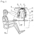
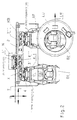
- Figs. 1 to 3 is a part of the interior of a Presented from the combat vehicle, of which only one Part of the roof panel D with a hatch LU (Fig. 2) indicated is, as well as part of the outer contour AK, behind which is arranged in the side wall of the tank T.
- the longitudinal direction of the vehicle is denoted by LR.
- In the illustrated part of the interior are two operator stations B1 and B2 arranged so that the operators transverse to the longitudinal direction LR to sit.
- a fold-up worktop AP arranged, behind which is a map board KB.
- the operators on the operator stations B1 and B2 should be able to take turns
- Computer to use not shown in detail is and for example, a fixed Basic unit and one lying on the worktop AP Keyboard can be and that with a screen device equipped, which in Figs. 1 to 3, depending after, whether it is in front of the first control panel B1, in a lashing position or in front of the second operator station B2 is denoted by 1, 1 'and 1 "', respectively is.
- This screen device should be between the two Operator stations B1 and B2 pushed back and forth be so that the two operators take turns It can work and it should, if it is is not needed, in a lashing 1 'movable in which it pushed back into a niche N. is that in the area of the outer wall next to the tank T is available.
- the display device 1 in a first horizontal direction I between the both operating stations B1 and B2 back and forth be. Furthermore, it should be in a second horizontal direction II, orthogonal to the first Direction I runs, be displaced backwards, make it into the between the two working positions lying lashing position are pushed backwards can.
- a linear roller rail 2 attached, parallel to the Longitudinal direction LR of the vehicle from the control station B1 to the control room 32 runs.
- a carriage led into the various positions shown in Fig. 1 to 3 3 3 'and 3 "' of the carriage 3 is a console platform 4 (or 4 ', 4 "') at which the display device 1 (1 ', 1 "') is suspended in a frame 6.
- the frame 6 is pivotable about a horizontal axis, so that the Screen device 1, as shown in Fig. 1, on the optimal viewing angle can be adjusted.
- the console platform 4 is connected to the carriage 3 via a movable guide device connected in 1 to 3 is generally denoted by 5 and further explained below with reference to FIGS. 4 to 6 in more detail becomes.
- a movable guide device connected in 1 to 3 is generally denoted by 5 and further explained below with reference to FIGS. 4 to 6 in more detail becomes.
- Figs. 4 to 6 show the console platform 4 and the carriage 3 with the guide device connecting them 5 in positions 1, 2 and 3, of which is assumed that the carriage 3 already in Direction I has been moved so far that he immediately opposite to the lashing position (see FIG. 2) located.
- the reference numbers are in positions 1 to 3 in FIG 4 to 6 for better distinction with 3, 3 '' and 3 '(see also Fig. 2) and 4, 4' ', 4' etc. designated.
- FIGS. 4 to 6 has the Guide device 5 two toggle pairs 7.1-7.2 and 8.1-8.2, which mirror each other mirror-symmetrical to the transverse center plane from console platform 4 and slide 3 opposite each other between the carriage 3 and the console platform 4 are arranged such that the axes their joints 7.3, 7.4, 7.5 or 8.3, 8.4, 8.5 perpendicular to the horizontal directions I and II spanned level.
- the one lever 7.1 and 8.1 of the toggle pairs are over the joints 7.3 and 8.3 with the console platform 4 and the other lever 7.2 or 8.2 on the joints 7.4 and 8.4 pivotally connected to the carriage 3.
- Of the Lever 7.1 is over the knee joint 7.5 with the lever 7.2 and the lever 8.1 on the knee joint 8.5 with the Lever 8.2 connected.
- FIGS. 4 and 6 are the levers 7.1 and 8.1 on the one hand and 7.2 and 8.2 on the other hand at different levels, so that when pivoting on each other and over the console platform 4 and under the carriage. 3 can slide away.
- the two levers 7.1 and 8.1 are via a gas spring 9 coupled together.
- This gas spring 9 has the Tendency to divide the two levers 7.1 and 8.1 apart Press and defines the spring-loaded state End positions of console platform 4 in positions 1 and 3.
- This guide device 5 The operation of this guide device 5 is the following:
- FIGS. 1 to 3 on the one hand and FIG. 4 on the other hand are easy to recognize to 6, only a few Handles needed, the console platform 4 with the display unit 1 on the one hand between the first and the second working position in front of the operator stations B1 and B2 to push back and forth and on the other hand, after the carriage 3 in the position opposite the lashing position has 3 'driven over the Positions 1, 2 and 3 in the lashing position and out of it out down.
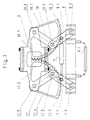
- Fig. 7 are with the embodiment 1 to 6 identical parts with the denoted by the same reference numerals.
- lever 17 and 18 are part of tooth segments that form have a circular section and their scope at least corresponds to the maximum tilt angle of the lever.
- the lever 17 containing toothed segment has Ribs 17.1 and 17.2, the ends of one hand with the inner end of the lever 17 and on the other hand are connected to the ends of a ring gear 17.3.
- the fulcrum of this sprocket corresponds to the Pivot axis 17.4 of the lever 17.
- the lever 18 containing toothed segment has two accordingly Ribs 18.1 and 18.2, which connect a ring gear 13.3.
- the sprockets 17.3 and 18.3 mesh with each other and the lever 17 is over the knee joint 17.5 with the lever 7.1 connected while the lever 18 via the knee joint 18.5 is connected to the lever 8.1. It can be easily read from Fig. 7, that in the Console platform 4 move through the positions 1 to 3 shown in FIG. 4 to 5 reaches a straight line is by the two sprockets 17.3 and 18.3 together expire.
Landscapes
- Engineering & Computer Science (AREA)
- General Engineering & Computer Science (AREA)
- Mechanical Engineering (AREA)
- Vehicle Step Arrangements And Article Storage (AREA)
- Fittings On The Vehicle Exterior For Carrying Loads, And Devices For Holding Or Mounting Articles (AREA)
Description
Claims (12)
- Konsole zur Halterung eines Bildschirmgerätes (1) mit einer Linear-Laufrollenschiene (2), die an der Decke (D) eines Innenraumes befestigbar ist und in einer ersten horizontalen Richtung (I) verläuft und auf der ein Schlitten (3) geführt ist, wobei im Bereich unterhalb des Schlittens (3) eine Konsolenplattform (4) angeordnet ist, die mit dem Schlitten (3) über eine bewegliche Führungsvorrichtung (5) verbunden ist, wobei an der Konsolenplattform (4) um eine horizontale Achse schwenkbar ein Rahmen (6) zum Tragen des Bildschirmgerätes (1) aufgehängt ist, dadurch gekennzeichnet, dass die Führungsvorrichtung (5) derart ausgebildet ist, dass die Konsolenplattform (4) in einer zweiten horizontalen Richtung (II) orthogonal zur Richtung (I) der Linear-Laufrollenschiene (2) unter dem Schlitten (3) hinweg vor- und zurückverschiebbar ist, wodurch die Konsole für den Innenraum eines Kampffahrzeugs mit zwei nebeneinander angeordneten Bedienungsplätzen (B1, B2) geeignet ist, in deren Bereich das Bildschirmgerät (1) zur abwechselnden Bedienung zwischen den beiden Bedienungsplätzen (B1, B2) bewegbar ist.
- Konsole nach Anspruch 1, dadurch gekennzeichnet, daß die Zurrposition des Bildschirmgerätes (1') in einer Nische (N) des Innenraums des Kampffahrzeugs angeordnet ist, in welche das Bildschirmgerät in der zweiten horizontalen Richtung (2) orthogonal zur Richtung (I) der Linear-Laufrollenschiene (2) zurückschiebbar ist.
- Konsole nach Anspruch 1 oder 2, dadurch gekennzeichnet, daß die bewegliche Führungsvorrichtung (5) zwei Kniehebelpaare (7.1, 7.2, 8.1, 8.2) aufweist, die einander spiegelsymmetrisch gegenüberliegend zwischen Schlitten (3) und Konsolenplattform (4) derart angeordnet sind, daß ihre Gelenkachsen senkrecht zur durch die erste und zweite horizontale Richtung (I, II) aufgespannten Ebene stehen, wobei jeweils ein Hebel (7.1, 8.1) jedes Kniehebelpaares schwenkbar an der Konsolenplattform (4) und der andere Hebel (7.2, 8.2) schwenkbar am Schlitten (3) angeordnet ist, und das die beiden Hebel (7.1 und 7.2 bzw. 8.1 und 8.2) verbindende Kniegelenk (7.5, 8.5) frei bewegbar ist und die beiden Hebel (7.1, 7.2 bzw. 8.1, 8.2) jedes Kniehebelpaares in unterschiedlichen Ebenen liegen derart, daß sie übereinander sowie unter dem Schlitten (3) und über der Konsolenplattform (4) hinweggleiten können.
- Konsole nach Anspruch 3, dadurch gekennzeichnet, daß ein Hebel (7.1) des einen Kniehebelpaares mit dem ihm entsprechenden Hebel (8.1) des anderen Kniehebelpaares über eine Gasfeder (9) verbunden ist.
- Konsole nach Anspruch 4, dadurch gekennzeichnet, daß die beiden Endlagen der Konsolenplattform (4) in der zweiten horizontalen Richtung (II) durch die ausgefederte Gasfeder (9) definiert sind.
- Konsole nach Anspruch 4 oder 5, dadurch gekennzeichnet, daß die Gasfeder (9) zwischen den beiden an der Konsolenplattform (4) angelenkten Hebeln (7.1, 8.1) jedes Kniehebelpaares angeordnet ist.
- Konsole nach Anspruch 6, dadurch gekennzeichnet, daß die Konsolenplattform (4) an ihrer Oberseite eine Vertiefung (4.3) für den Durchtritt der Gasfeder (9) aufweist.
- Konsole nach einem der Ansprüche 1 bis 7, dadurch gekennzeichnet, daß von den Bedienungsplätzen (B1, B2) aus gesehen, hinter der Linear-Laufrollenschiene (2) an mindestens einer vorgegebenen Stelle eine fahrzeugfeste Falle (10) angeordnet ist, in welche die Konsolenplattform (4, 4') in einer Zurrposition im zurückgeschobenen Zustand einrastet.
- Konsole nach den Ansprüchen 4 und 8, dadurch gekennzeichnet, daß die Falle (10) eine Ausnehmung (10.1) besitzt, in welche ein Vorsprung (4.2') der Konsolenplattform (4') unter der Kraftwirkung der Gasfeder (9') einrastet.
- Konsole nach einem der Ansprüche 1 bis 9, dadurch gekennzeichnet, daß die Arbeitspositionen der Konsolenplattform (4, 4"') an den Enden der Linear-Laufrollenschiene (2) liegen und zwischen diesen Arbeitspositionen eine Zurrposition der Konsolenplattform (4') angeordnet ist.
- Konsole nach Anspruch 3 und gegebenenfalls einem der Ansprüche 4 bis 10, gekennzeichnet durch, eine Geradführungsvorrichtung für die Bewegung der Konsolenplattform (4) in der zweiten horizontalen Richtung (II), welche zwei jeweils mit den am Schlitten (3) angelenkten Hebeln (17, 18) fest verbundene miteinader kämmende Zahnsegmente (17.3, 18.3) in Form eines Kreisausschnitts aufweist, deren Umfang mindestens dem maximalen Schwenkwinkel dieser Hebel (17, 18) entspricht, deren Drehachsen jeweils mit den Schwenkachsen (17.4, 18.4) der beiden Hebel (17, 18) zusammenfallen und deren Radius dem halben Abstand der beiden Schwenkachsen (17.4, 18.4) voneinander entspricht.
- Konsole nach Anspruch 11, dadurch gekennzeichnet, daß die beiden am Schlitten (3) angelenkten Hebel (17,18) in die Zahnsegmente (17.3, 18.3) integriert und auf der winkelhalbierenden ihres Umfangswinkels angeordnet sind.
Applications Claiming Priority (2)
| Application Number | Priority Date | Filing Date | Title |
|---|---|---|---|
| DE19810021A DE19810021A1 (de) | 1998-03-09 | 1998-03-09 | Bewegbare Konsole zur Halterung eines Arbeitsgerätes, insbesondere eines Bildschirmgerätes im Innenraum eines Fahrzeugs, insbesondere eines Kampffahrzeugs |
| DE19810021 | 1998-03-09 |
Publications (2)
| Publication Number | Publication Date |
|---|---|
| EP0942221A1 EP0942221A1 (de) | 1999-09-15 |
| EP0942221B1 true EP0942221B1 (de) | 2004-01-14 |
Family
ID=7860199
Family Applications (1)
| Application Number | Title | Priority Date | Filing Date |
|---|---|---|---|
| EP99103334A Expired - Lifetime EP0942221B1 (de) | 1998-03-09 | 1999-02-20 | Konsole zur Halterung eines Arbeitsgerätes, insbesondere eines Bildschirmgerätes im Innenraum eines Fahrzeugs, insbesondere eines Kampffahrzeugs |
Country Status (3)
| Country | Link |
|---|---|
| EP (1) | EP0942221B1 (de) |
| DE (2) | DE19810021A1 (de) |
| ES (1) | ES2213302T3 (de) |
Families Citing this family (5)
| Publication number | Priority date | Publication date | Assignee | Title |
|---|---|---|---|---|
| ITMI20010758A1 (it) * | 2001-04-10 | 2002-10-10 | Elnagh Spa | Dispositivo di supporto e di orientamento per un televisore all'interno di un autoveicolo |
| DE10133143A1 (de) * | 2001-07-07 | 2003-01-23 | Rheinmetall Landsysteme Gmbh | Gepanzertes Transportfahrzeug mit einem Gefechtsstand |
| DE10144369A1 (de) * | 2001-09-10 | 2003-03-27 | Rheinmetall Landsysteme Gmbh | Vorrichtung für ein gepanzertes Transportfahrzeug als Kartenbrett-, Arbeitstisch- und Stauschrankkombination |
| FR2913801B1 (fr) * | 2007-03-14 | 2009-06-05 | Nexter Systems Sa | Dispositif de fixation d'un ecran plat sur un simulateur de vehicule |
| DE102013101423B4 (de) | 2013-02-13 | 2014-09-04 | Krauss-Maffei Wegmann Gmbh & Co. Kg | Militärisches Fahrzeug sowie Verfahren zum Betrieb eines militärischen Fahrzeugs |
Family Cites Families (8)
| Publication number | Priority date | Publication date | Assignee | Title |
|---|---|---|---|---|
| FR2593046B1 (fr) * | 1986-01-22 | 1988-12-09 | Maurel Guy | Poste de travail ergonomique pour la pratique du dessin assiste par ordinateur. |
| US4836478A (en) * | 1987-10-15 | 1989-06-06 | Ergotron, Inc. | Suspension system for personal computers and monitors |
| US4964606A (en) * | 1989-10-26 | 1990-10-23 | Ncr Corporation | Overhead mount for a CRT |
| DE4007011C2 (de) * | 1990-03-06 | 1999-11-18 | Helmuth Heigl | Positioniervorrichtung |
| JPH078032B2 (ja) * | 1990-06-29 | 1995-01-30 | 三菱電機株式会社 | テレビジヨン受像機の回動装置 |
| DE4120260C1 (en) * | 1991-06-19 | 1993-01-07 | Siemens Ag, 8000 Muenchen, De | Balanced holder for medical appts. component - has swivelable combined arm with component holding and lever arm sections |
| DE19700328A1 (de) * | 1997-01-08 | 1997-05-22 | Ruerup Hans Christian | Der sich elektrisch bewegende Bildschirmträger |
| DE29805542U1 (de) * | 1998-03-26 | 1998-06-04 | F. Walter Hänel GmbH, 81829 München | Gelenkkörper, insbesondere zur schwenkbaren Befestigung eines Monitors |
-
1998
- 1998-03-09 DE DE19810021A patent/DE19810021A1/de not_active Withdrawn
-
1999
- 1999-02-20 DE DE59908272T patent/DE59908272D1/de not_active Expired - Lifetime
- 1999-02-20 ES ES99103334T patent/ES2213302T3/es not_active Expired - Lifetime
- 1999-02-20 EP EP99103334A patent/EP0942221B1/de not_active Expired - Lifetime
Also Published As
| Publication number | Publication date |
|---|---|
| DE19810021A1 (de) | 1999-09-16 |
| DE59908272D1 (de) | 2004-02-19 |
| EP0942221A1 (de) | 1999-09-15 |
| ES2213302T3 (es) | 2004-08-16 |
Similar Documents
| Publication | Publication Date | Title |
|---|---|---|
| DE102012112527B3 (de) | Nutzfahrzeugsitz mit integrierter Drehverstelleinrichtung | |
| DE68902427T2 (de) | Motorisch verstellbare armlehne. | |
| DE10159919A1 (de) | Verkleidungsteil mit ausklappbarem Bildschirm | |
| DE69319423T2 (de) | Schwenkeinrichtung | |
| EP0670232B1 (de) | Fahrzeugdach mit einer Folge von Lamellen | |
| EP1614650A2 (de) | Treppenschrägaufzug | |
| EP0403800A1 (de) | System mit einem ausleger zum aufnehmen von auf laufrollen gelagerten gegenständen | |
| DE102019122544A1 (de) | Konsoleneinrichtung für Nutzfahrzeugkabine | |
| EP1085962A1 (de) | Vorrichtung zum handhaben mindestens eines spannrahmens, insbesondere für die montage von rohkarosserien von fahrzeugen | |
| DE3713807A1 (de) | Sonnenblende fuer kraftfahrzeuge | |
| EP0942221A1 (de) | Bewegbare Konsole zur Halterung eines Arbeitsgerätes, insbesondere eines Bildschirmgerätes im Innenraum eines Fahrzeugs, insbesondere eines Kampffahrzeugs | |
| DE112021006184T5 (de) | Strahlungsinspektionsvorrichtung | |
| DE19737678A1 (de) | Fahrzeug mit Rahmenabstützung | |
| DE3922400C2 (de) | ||
| EP0788767B1 (de) | Röntgendiagnostikgerät | |
| DE10065130B4 (de) | Windschild für Motorräder | |
| DE602004004593T2 (de) | Fahrzeug mit integriertem schiebedachmodul | |
| DE10317290B4 (de) | Ankopplungsvorrichtung für ein Transportsystem | |
| EP3572056B1 (de) | Tragenlagerungseinrichtung | |
| EP1337712A1 (de) | Bodenverdichtungsmaschine | |
| DE102012109508B3 (de) | Sitz für eine Krankabine oder dergleichen | |
| DE19730966A1 (de) | Auflage-, Schweiß- und Montagevorrichtung für Großbaugruppen im Fahrzeugbau, insbesondere Schienenfahrzeugbau | |
| DE102021207990A1 (de) | Lenksäule mit einer schwenkbaren Aufnahme für eine Lenkhandhabe | |
| EP0732294B1 (de) | Taschenfalzmaschine | |
| DE602004002555T2 (de) | Verstellbarer Fahrzeugsitz und Kraftfahrzeug mit einem solchen verstellbarem Sitz |
Legal Events
| Date | Code | Title | Description |
|---|---|---|---|
| PUAI | Public reference made under article 153(3) epc to a published international application that has entered the european phase |
Free format text: ORIGINAL CODE: 0009012 |
|
| AK | Designated contracting states |
Kind code of ref document: A1 Designated state(s): DE ES FR GB GR IT NL SE |
|
| AX | Request for extension of the european patent |
Free format text: AL;LT;LV;MK;RO;SI |
|
| 17P | Request for examination filed |
Effective date: 19990810 |
|
| AKX | Designation fees paid |
Free format text: DE ES FR GB GR IT NL SE |
|
| 17Q | First examination report despatched |
Effective date: 20020911 |
|
| GRAP | Despatch of communication of intention to grant a patent |
Free format text: ORIGINAL CODE: EPIDOSNIGR1 |
|
| RTI1 | Title (correction) |
Free format text: HOLDER FOR SUPPORTING AN APPARATUS, PARTICULARLY A VIDEO DISPLAY INSIDE A VEHICLE, PARTICULARLY A COMBAT VEHICLE |
|
| GRAS | Grant fee paid |
Free format text: ORIGINAL CODE: EPIDOSNIGR3 |
|
| GRAA | (expected) grant |
Free format text: ORIGINAL CODE: 0009210 |
|
| AK | Designated contracting states |
Kind code of ref document: B1 Designated state(s): DE ES FR GB GR IT NL SE |
|
| REG | Reference to a national code |
Ref country code: GB Ref legal event code: FG4D Free format text: NOT ENGLISH |
|
| PGFP | Annual fee paid to national office [announced via postgrant information from national office to epo] |
Ref country code: GR Payment date: 20040123 Year of fee payment: 6 |
|
| REF | Corresponds to: |
Ref document number: 59908272 Country of ref document: DE Date of ref document: 20040219 Kind code of ref document: P |
|
| PG25 | Lapsed in a contracting state [announced via postgrant information from national office to epo] |
Ref country code: GR Free format text: LAPSE BECAUSE OF FAILURE TO SUBMIT A TRANSLATION OF THE DESCRIPTION OR TO PAY THE FEE WITHIN THE PRESCRIBED TIME-LIMIT Effective date: 20040414 |
|
| REG | Reference to a national code |
Ref country code: SE Ref legal event code: TRGR |
|
| GBV | Gb: ep patent (uk) treated as always having been void in accordance with gb section 77(7)/1977 [no translation filed] |
Effective date: 20040114 |
|
| ET | Fr: translation filed | ||
| REG | Reference to a national code |
Ref country code: ES Ref legal event code: FG2A Ref document number: 2213302 Country of ref document: ES Kind code of ref document: T3 |
|
| PLBE | No opposition filed within time limit |
Free format text: ORIGINAL CODE: 0009261 |
|
| STAA | Information on the status of an ep patent application or granted ep patent |
Free format text: STATUS: NO OPPOSITION FILED WITHIN TIME LIMIT |
|
| 26N | No opposition filed |
Effective date: 20041015 |
|
| REG | Reference to a national code |
Ref country code: GB Ref legal event code: 710B Free format text: EXTENSION APPLICATION: APPLICATION FOR EXTENSION OF THE PERIOD(S) PRESCRIBED BY RULE(S) SCHEDULE 4 PARA 2 FILED ON 20050304. |
|
| GBT | Gb: translation of ep patent filed (gb section 77(6)(a)/1977) |
Effective date: 20050802 |
|
| REG | Reference to a national code |
Ref country code: GB Ref legal event code: 710B Free format text: EXTENSION APPLICATION: PERIOD(S) PRESCRIBED BY RULE(S) SCHEDULE 4 PARA 2 EXTENDED UNDER RULE 110(6) IN ACCORDANCE WITH THE DECISION OF THE COMPTROLLER DATED 20050523. THE PATENT/APPLICATION IS REINSTATED SUBJECT TO SPECIAL TERMS FOR THIRD PARTY INTERESTS. |
|
| REG | Reference to a national code |
Ref country code: FR Ref legal event code: PLFP Year of fee payment: 18 |
|
| REG | Reference to a national code |
Ref country code: FR Ref legal event code: PLFP Year of fee payment: 19 |
|
| PGFP | Annual fee paid to national office [announced via postgrant information from national office to epo] |
Ref country code: FR Payment date: 20170220 Year of fee payment: 19 Ref country code: DE Payment date: 20170228 Year of fee payment: 19 Ref country code: SE Payment date: 20170221 Year of fee payment: 19 |
|
| PGFP | Annual fee paid to national office [announced via postgrant information from national office to epo] |
Ref country code: NL Payment date: 20170220 Year of fee payment: 19 Ref country code: GB Payment date: 20170221 Year of fee payment: 19 |
|
| PGFP | Annual fee paid to national office [announced via postgrant information from national office to epo] |
Ref country code: IT Payment date: 20170217 Year of fee payment: 19 Ref country code: ES Payment date: 20170220 Year of fee payment: 19 |
|
| REG | Reference to a national code |
Ref country code: DE Ref legal event code: R119 Ref document number: 59908272 Country of ref document: DE |
|
| REG | Reference to a national code |
Ref country code: SE Ref legal event code: EUG |
|
| REG | Reference to a national code |
Ref country code: NL Ref legal event code: MM Effective date: 20180301 |
|
| GBPC | Gb: european patent ceased through non-payment of renewal fee |
Effective date: 20180220 |
|
| PG25 | Lapsed in a contracting state [announced via postgrant information from national office to epo] |
Ref country code: SE Free format text: LAPSE BECAUSE OF NON-PAYMENT OF DUE FEES Effective date: 20180221 |
|
| REG | Reference to a national code |
Ref country code: FR Ref legal event code: ST Effective date: 20181031 |
|
| PG25 | Lapsed in a contracting state [announced via postgrant information from national office to epo] |
Ref country code: NL Free format text: LAPSE BECAUSE OF NON-PAYMENT OF DUE FEES Effective date: 20180301 |
|
| PG25 | Lapsed in a contracting state [announced via postgrant information from national office to epo] |
Ref country code: DE Free format text: LAPSE BECAUSE OF NON-PAYMENT OF DUE FEES Effective date: 20180901 |
|
| PG25 | Lapsed in a contracting state [announced via postgrant information from national office to epo] |
Ref country code: IT Free format text: LAPSE BECAUSE OF NON-PAYMENT OF DUE FEES Effective date: 20180220 Ref country code: GB Free format text: LAPSE BECAUSE OF NON-PAYMENT OF DUE FEES Effective date: 20180220 Ref country code: FR Free format text: LAPSE BECAUSE OF NON-PAYMENT OF DUE FEES Effective date: 20180228 |
|
| REG | Reference to a national code |
Ref country code: ES Ref legal event code: FD2A Effective date: 20190801 |
|
| PG25 | Lapsed in a contracting state [announced via postgrant information from national office to epo] |
Ref country code: ES Free format text: LAPSE BECAUSE OF NON-PAYMENT OF DUE FEES Effective date: 20180221 |