EP0940592A1 - Kombiniertes Kugel- und Gleitlager - Google Patents
Kombiniertes Kugel- und Gleitlager Download PDFInfo
- Publication number
- EP0940592A1 EP0940592A1 EP99301563A EP99301563A EP0940592A1 EP 0940592 A1 EP0940592 A1 EP 0940592A1 EP 99301563 A EP99301563 A EP 99301563A EP 99301563 A EP99301563 A EP 99301563A EP 0940592 A1 EP0940592 A1 EP 0940592A1
- Authority
- EP
- European Patent Office
- Prior art keywords
- bearing
- outer ring
- inner ring
- ball
- ring
- Prior art date
- Legal status (The legal status is an assumption and is not a legal conclusion. Google has not performed a legal analysis and makes no representation as to the accuracy of the status listed.)
- Granted
Links
Images


Classifications
-
- F—MECHANICAL ENGINEERING; LIGHTING; HEATING; WEAPONS; BLASTING
- F16—ENGINEERING ELEMENTS AND UNITS; GENERAL MEASURES FOR PRODUCING AND MAINTAINING EFFECTIVE FUNCTIONING OF MACHINES OR INSTALLATIONS; THERMAL INSULATION IN GENERAL
- F16C—SHAFTS; FLEXIBLE SHAFTS; ELEMENTS OR CRANKSHAFT MECHANISMS; ROTARY BODIES OTHER THAN GEARING ELEMENTS; BEARINGS
- F16C39/00—Relieving load on bearings
- F16C39/02—Relieving load on bearings using mechanical means
-
- F—MECHANICAL ENGINEERING; LIGHTING; HEATING; WEAPONS; BLASTING
- F16—ENGINEERING ELEMENTS AND UNITS; GENERAL MEASURES FOR PRODUCING AND MAINTAINING EFFECTIVE FUNCTIONING OF MACHINES OR INSTALLATIONS; THERMAL INSULATION IN GENERAL
- F16C—SHAFTS; FLEXIBLE SHAFTS; ELEMENTS OR CRANKSHAFT MECHANISMS; ROTARY BODIES OTHER THAN GEARING ELEMENTS; BEARINGS
- F16C19/00—Bearings with rolling contact, for exclusively rotary movement
- F16C19/52—Bearings with rolling contact, for exclusively rotary movement with devices affected by abnormal or undesired conditions
- F16C19/522—Bearings with rolling contact, for exclusively rotary movement with devices affected by abnormal or undesired conditions related to load on the bearing, e.g. bearings with load sensors or means to protect the bearing against overload
-
- F—MECHANICAL ENGINEERING; LIGHTING; HEATING; WEAPONS; BLASTING
- F16—ENGINEERING ELEMENTS AND UNITS; GENERAL MEASURES FOR PRODUCING AND MAINTAINING EFFECTIVE FUNCTIONING OF MACHINES OR INSTALLATIONS; THERMAL INSULATION IN GENERAL
- F16C—SHAFTS; FLEXIBLE SHAFTS; ELEMENTS OR CRANKSHAFT MECHANISMS; ROTARY BODIES OTHER THAN GEARING ELEMENTS; BEARINGS
- F16C21/00—Combinations of sliding-contact bearings with ball or roller bearings, for exclusively rotary movement
-
- F—MECHANICAL ENGINEERING; LIGHTING; HEATING; WEAPONS; BLASTING
- F16—ENGINEERING ELEMENTS AND UNITS; GENERAL MEASURES FOR PRODUCING AND MAINTAINING EFFECTIVE FUNCTIONING OF MACHINES OR INSTALLATIONS; THERMAL INSULATION IN GENERAL
- F16C—SHAFTS; FLEXIBLE SHAFTS; ELEMENTS OR CRANKSHAFT MECHANISMS; ROTARY BODIES OTHER THAN GEARING ELEMENTS; BEARINGS
- F16C33/00—Parts of bearings; Special methods for making bearings or parts thereof
- F16C33/02—Parts of sliding-contact bearings
- F16C33/04—Brasses; Bushes; Linings
- F16C33/06—Sliding surface mainly made of metal
- F16C33/10—Construction relative to lubrication
- F16C33/1025—Construction relative to lubrication with liquid, e.g. oil, as lubricant
- F16C33/103—Construction relative to lubrication with liquid, e.g. oil, as lubricant retained in or near the bearing
- F16C33/104—Construction relative to lubrication with liquid, e.g. oil, as lubricant retained in or near the bearing in a porous body, e.g. oil impregnated sintered sleeve
-
- F—MECHANICAL ENGINEERING; LIGHTING; HEATING; WEAPONS; BLASTING
- F16—ENGINEERING ELEMENTS AND UNITS; GENERAL MEASURES FOR PRODUCING AND MAINTAINING EFFECTIVE FUNCTIONING OF MACHINES OR INSTALLATIONS; THERMAL INSULATION IN GENERAL
- F16C—SHAFTS; FLEXIBLE SHAFTS; ELEMENTS OR CRANKSHAFT MECHANISMS; ROTARY BODIES OTHER THAN GEARING ELEMENTS; BEARINGS
- F16C33/00—Parts of bearings; Special methods for making bearings or parts thereof
- F16C33/30—Parts of ball or roller bearings
- F16C33/58—Raceways; Race rings
- F16C33/583—Details of specific parts of races
-
- F—MECHANICAL ENGINEERING; LIGHTING; HEATING; WEAPONS; BLASTING
- F16—ENGINEERING ELEMENTS AND UNITS; GENERAL MEASURES FOR PRODUCING AND MAINTAINING EFFECTIVE FUNCTIONING OF MACHINES OR INSTALLATIONS; THERMAL INSULATION IN GENERAL
- F16C—SHAFTS; FLEXIBLE SHAFTS; ELEMENTS OR CRANKSHAFT MECHANISMS; ROTARY BODIES OTHER THAN GEARING ELEMENTS; BEARINGS
- F16C19/00—Bearings with rolling contact, for exclusively rotary movement
- F16C19/02—Bearings with rolling contact, for exclusively rotary movement with bearing balls essentially of the same size in one or more circular rows
- F16C19/04—Bearings with rolling contact, for exclusively rotary movement with bearing balls essentially of the same size in one or more circular rows for radial load mainly
- F16C19/06—Bearings with rolling contact, for exclusively rotary movement with bearing balls essentially of the same size in one or more circular rows for radial load mainly with a single row or balls
-
- F—MECHANICAL ENGINEERING; LIGHTING; HEATING; WEAPONS; BLASTING
- F16—ENGINEERING ELEMENTS AND UNITS; GENERAL MEASURES FOR PRODUCING AND MAINTAINING EFFECTIVE FUNCTIONING OF MACHINES OR INSTALLATIONS; THERMAL INSULATION IN GENERAL
- F16C—SHAFTS; FLEXIBLE SHAFTS; ELEMENTS OR CRANKSHAFT MECHANISMS; ROTARY BODIES OTHER THAN GEARING ELEMENTS; BEARINGS
- F16C2370/00—Apparatus relating to physics, e.g. instruments
- F16C2370/12—Hard disk drives or the like
Definitions
- the present invention relates to a composite bearing structure and more particularly to a composite bearing structure composed of a combination of single row ball bearings and cylindrical bearings.
- FIG 17 shows a sectional view through a single row ball bearing.
- the outer ring 101 freely inclines through an angle of ⁇ on top of ball 102.
- a rotating body such as the hub of a spindle motor is mounted on outer ring 101, this rotating body will vibrate in both the axial and radial directions with relation to inner ring 103, and so the rotation will be unstable.
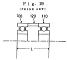
- two single row ball bearings 100 and 110 are fixed together in a parallel assembly, or, as shown in FIG 19, to further reduce the rotational vibration, a spacer 120 is mounted between the two single row ball bearings 100 and 110, increasing the space between ball bearing 100 and ball bearing 110, preventing rotational vibration and achieving stable high precision rotation.
- the present invention has been accomplished in view of the above-mentioned problems and it is an object of the invention to provide a bearing structure in which a single ball bearing is used in such a way as to prevent rotational vibration is the same way as if two ball bearings were used, and in addition to provide a low cost, thin type ball bearing structure.
- the present invention provides a structure using one single row ball bearing (the smallest unit which can be used in a ball bearing), which, in order to solve the problem of inclination and vibration in the inner and outer rings, uses a sintered, oil-impregnated bearing or alternatively, a non-oil-impregnated dry bearing, a fluid bearing, etc.(There are defined with a friction bearing.) where an inner or an outer ring of the friction bearing is mounted either on one side or on both sides, in a structure which prevents inclined rotation.
- the radial load is mainly received by the ball, and when the inner and outer rings are about to vibrate and incline, a sintered, oil-impregnated bearing mounted either on one side or on both sides of the inner ring or outer ring closes the gap and slightly contacts the opposing inner or outer ring thus preventing the inclination, said contact surface being, because it is the inner or outer ring surface of the single row ball bearing, a very precisely finished surface, and thus the frictional loss from the inclination load is slight.
- the thrust load is all received by the ball.
- the thrust load is also all received by the ball, and the friction loss received by the inclination-preventing sintered, oil-impregnated bearing is very slight, and therefore there is no great influence on either the rotational precision or the lifetime reliability.
- the present invention makes possible a bearing with minimal width, which can be formed by a composite bearing having an anti-collapse function, and which does not require much increase of the width of the single row ball bearing.
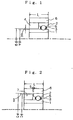
- a single composite bearing comprising an inner ring 1, having a width L of the size necessary to restrain the inclination of the axis within the permitted range, and an outer ring 2, having a width which is half the width of the above mentioned width L, which is mounted above the outside half of inner ring 1 and separated from inner ring 1 by a gap.
- a ball 3 is fitted into this gap between the rings and rests in grooves made in each ring. The ball 3 is prevented from escaping from the groove by retainer 5.
- Inner ring 1 has an external form which is superfinished to high precision in one piece and contains the ball groove described above.
- the outside of outer ring 2 is press fitted into outer ring sleeve 6, which is made of metal having a cylindrical form of width L.
- Cylindrically-shaped sintered, oil-impregnated bearing 4 is press fitted into the space formed by the inner parts of outer ring 2, ball 3 and retainer 5.
- the outer diameter of this sintered, oil-impregnated bearing 4 is the same as the inner diameter of outer ring sleeve 6, and its inner diameter is slightly larger than the outer diameter of inner ring 1. Because of this, sintered, oil-impregnated bearing 4 is press fitted firmly to the inner side of outer ring sleeve 6 and forms a small gap g above the peripheral face of inner ring 1.
- This inclination suppression gap g in order to prevent the inclination from exceeding the permitted range, is determined by the dimensions A and B shown in FIG 1, and accordingly extremely high precision processing is required.
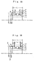
- FIGS 3, 5 and 7 show basically similar structures to the above, in which a single composite bearing has an inclination suppression gap g formed on the inner ring 1 side. These structures will be described in detail below.
- a single composite bearing shown in FIG 3 has a structure in which the single composite bearing and the inclination suppression gap g are established on the inner ring 1 side.
- Sintered, oil-impregnated bearing 4 processed to the dimensions outer diameter C, inner diameter B and width W, is combined with a single row ball bearing formed by inner ring 1, outer ring 2, ball 3 and retainer 5.
- This embodiment does not require the outer ring sleeve 6 of the embodiment shown in FIG 1, and instead the parts can directly assembled together.
- This embodiment has the advantage of allowing the diametrical dimension to be reduced.
- a single composite bearing shown in FIG 5 has a structure in which the single composite bearing and the inclination suppression gap g are established on the inner ring 1 side.
- Sintered, oil-impregnated bearing 4 is combined with a single row ball bearing formed by inner ring 1, outer ring 2, ball 3 and retainer 5.
- outer ring 2 has a stepped large diameter part F, and sintered, oil-impregnated bearing 4 is press fitted or bonded onto this stepped large diameter part F of outer ring 2 to form a structure which, together with inner ring 1, maintains inclination suppression gap g.
- sintered, oil-impregnated bearing 4 is fixed together with outer ring 2 to make a one-piece single composite bearing.
- This embodiment is easy to use, easy to handle, and does not require an outer ring spacer, and is thus advantageous from the cost viewpoint and because it allows size reductions in the diametrical direction. Also, assembly precision is high.
- a single composite bearing shown in FIG 7 has a structure in which the single composite bearing and the inclination suppression gap g are established on the inner ring 1 side.
- Sintered, oil-impregnated bearing 4 is combined with a single row ball bearing formed by inner ring 1, outer ring 2, ball 3 and retainer 5.
- Sintered, oil-impregnated bearing 4 is press fitted or bonded onto the inner diameter part G of outer ring 2 to form a fixed structure which maintains inclination suppression gap g with the dimensions A and B on the inner ring side.
- sintered, oil-impregnated bearing 4 is fixed together with outer ring 2 to make a one-piece single composite bearing, with the outer diameter of inner ring 1 and the inner diameter of outer ring 2 both processed to standard bearing dimensions.
- This embodiment is easy to use, easy to handle, does not require an outer ring spacer or outer ring step processing, and is thus most advantageous from the cost viewpoint and because it allows size reductions in the diametrical direction. Also, assembly precision is high.
- a single composite bearing comprises an inner ring 1, having a width L of the size necessary to restrain the inclination of the axis within the permitted range, and an outer ring 2, having a width which is half the width of the above mentioned width L, which is mounted above the outside half of inner ring 1 and separated from inner ring 1 by a gap.
- a ball 3 is fitted into this gap between the rings and rests in grooves made in each ring. The ball 3 is prevented from escaping from the groove by retainer 5.
- Inner ring 1 has an external form which is superfinished to high precision in one piece and contains the ball groove described above.
- the outside of outer ring 2 is press fitted into outer ring sleeve 6, which is made of metal having a cylindrical form of width L.
- Sintered, oil-impregnated bearing 7 is arranged in the space formed by the inner parts of outer ring 2, ball 3 and retainer 5. As shown in FIG 2, this sintered, oil-impregnated bearing 7 has an outer diameter which is smaller than the inner diameter of outer ring sleeve 6, and an inner diameter of the same size as the outer diameter of inner ring 1. Because of this, sintered, oil-impregnated bearing 7 is press fitted firmly to the outer side of inner ring 1 and forms a small gap g with the inner peripheral face of outer ring 2. This inclination suppression gap g, in order to prevent the inclination from exceeding the permitted range, is determined by the dimensions C and D shown in FIG 2, and accordingly extremely high precision processing is required.
- FIGS 4, 6 and 8 show basically similar structures to the above, in which a single composite bearing has an inclination suppression gap g formed on the inner ring 1 side. These structures will be described in detail below.
- the inclination suppression gap g is established with outer ring 2.
- Outer ring 2 is assembled by bonding or press fitting to inner diameter E of the opposing part, thus forming inclination suppression gap g with inner diameter E of the opposing part.
- This composite bearing structure as shown in FIGS 3 and 4 has the advantage of allowing the diametrical dimension to be reduced.
- the inclination suppression gap g is established with the side of outer ring 2.
- outer ring 2 has a processed stepped section with large diameter F, and sintered, oil-impregnated bearing 7 is press fitted or bonded onto inner ring 1 to form a structure which maintains inclination suppression gap g with this stepped large diameter part F and also establishes gap S with the edge side of the outer ring.
- sintered, oil-impregnated bearing 7 is fixed together with inner ring 1 to make a one-piece single composite bearing.
- This embodiment is easy to use, easy to handle, and does not require an outer ring spacer, and is thus advantageous from the cost viewpoint and because it allows size reductions in the diametrical direction. Also, assembly precision is high.
- the inclination suppression gap g is established with the side of outer ring 2.
- sintered, oil-impregnated bearing 7 is fixed together with inner ring 1 to make a one-piece single composite bearing, with the outer diameter of inner ring 1 and the inner diameter of outer ring 2 both processed to standard bearing dimensions.
- This structure is easy to use, easy to handle, does not require an outer ring spacer or outer ring step processing, and is thus most advantageous from the cost viewpoint and because it allows size reductions in the diametrical direction. Also, assembly precision is high.
- a double composite bearing comprises an inner ring 1, having a width L of the size necessary to restrain the inclination of the axis within the permitted range, and an outer ring 2, having a width which is the same as the above mentioned width L, which is mounted above the outside of inner ring 1 and separated from inner ring 1 by a gap.
- a ball 3 is fitted into the central space between the two rings and rests in a groove in the outside of inner ring 1 and a groove in the inside of outer ring 2. The ball 3 is prevented from escaping from the ball groove by retainers 5.
- Inner ring 1 is super finished in one piece to high precision in a shape having the ball groove described above.
- Half-sintered oil-impregnated bearings 8 and 9, each having width I, are fitted into the space between inner ring 1 and outer ring 2 on each side of ball 3.
- the outer diameters of half-sintered oil-impregnated bearings 8 and 9 are the same as the inner diameter of outer ring 2, and their inner diameters are slightly larger than the inner diameter of inner ring 1. Because of this, half-sintered, oil-impregnated bearings 8 and 9 are press fitted firmly to the inner side of outer ring 2 and form a small gap g with the peripheral face of inner ring 1.
- This inclination suppression gap g in order to prevent the inclination from exceeding the permitted range, is determined by the dimensions A and B shown in FIG 9, and accordingly extremely high precision processing is required.
- FIGS 11, 13 and 15 show basically similar structures to the above, in which a double composite bearing has an inclination suppression gap g formed on the inner ring 1 side. These structures will be described in detail below.
- a double composite bearing shown in FIG 11 has a structure in which the inclination suppression gap g is established on the inner ring 1 side.
- the opposing parts may be freely designed as regards shape, and can be directly assembled together with the opposing parts with no need for an outer sleeve ring 6. This has the advantage of allowing the diametrical dimension to be reduced.
- a double composite bearing shown in FIG 13 has a structure in which the inclination suppression gap g is established on the inner ring 1 side.
- a double composite bearing shown in FIG 15 has a structure in which the inclination suppression gap g is established on the inner ring 1 side.
- a double composite bearing comprises an inner ring 1, having a width L of the size necessary to restrain the inclination of the axis within the permitted range, and an outer ring 2, having a width which is the same as the above mentioned width L, which is mounted above the outside of inner ring 1 and separated from inner ring 1 by a gap.
- a ball 3 is fitted into the central space between the two rings and rests in a groove in the outside of inner ring 1 and a groove in the inside of outer ring 2. The ball 3 is prevented from escaping from the ball groove by retainers 5.
- Inner ring 1 is super finished in one piece to high precision in a shape having the ball groove described above.
- Half-sintered oil-impregnated bearings 10 and 11, each having width I, are fitted into the space between inner ring 1 and outer ring 2 on each side of ball 3.
- the outer diameters of half-sintered oil-impregnated bearings 10 and 11 are slightly smaller than the inner diameter of outer ring 2, and their inner diameters are the same as the outer diameter of inner ring 1. Because of this, half-sintered, oil-impregnated bearings 10 and 11 are press fitted firmly to the outer side of inner ring 1 and form a small gap g with the inner peripheral face of outer ring 2.
- This inclination suppression gap g in order to prevent the inclination from exceeding the permitted range, is determined by the dimensions C and G shown in FIG 10, and accordingly extremely high precision processing is required.
- outer ring 2 side or inner ring 1 side begins to incline, part of one surface C of half-sintered, oil-impregnated bearings 10 and 11 will contact surface G of outer ring 2 and prevent any further inclination of the axis from occurring.
- the size of the inclination of the axis can be determined by the size of inclination suppression gap g.
- FIGS 12, 14 and 16 show basically similar structures to the above, in which a double composite bearing has an inclination suppression gap g formed on the outer ring 2 side. These structures will be described in detail below.
- a double composite bearing shown in FIG 12 has a structure in which the inclination suppression gap g is established on the outer ring 2 side.
- the assembly is formed as a single piece unlike the set shown in the example of FIG 14, and so both handling and assembly are easy.
- the opposing parts may be freely designed as regards shape, and can be directly assembled together with the opposing parts with no need for an outer sleeve ring. This has the advantage of allowing the diametrical dimension to be made more compact.
- a double composite bearing shown in FIG 14 has a structure in which the inclination suppression gap g is established on the outer ring side.
- Sintered, oil-impregnated bearings 10 and 11, processed to the dimensions outer diameter C, inner diameter B and width I, are press fitted or bonded onto the outer diameter part of inner ring 1 and mounted, so as to preserve a gap S, on either side of outer ring 2 of the single row ball bearing formed by inner ring 1, outer ring 2, ball 3 and retainer 5, thus forming a structure which establishes inclination suppression gap g with outer ring sleeve 6.
- the outer diameter dimension of the double composite bearing becomes large, but its one-piece construction offers the advantages of easy handling and assembly.
- a double composite bearing shown in FIG 16 has a structure in which the inclination suppression gap g is established on the outer ring 2 side.
- the present invention has been described in terms of the above embodiments, but within the range of the gist of this invention various formats and applications are possible.
- inner ring 2 as a rotating and stopping axis with no hollow spaces
- the present invention provides a structure using one single row ball bearing with 1 ball (the smallest unit which can be used in a ball bearing), which, in order to solve the problem of inclination and vibration in the inner and outer rings, uses a sintered, oil-impregnated bearing with the objective of preventing inclination, where an inner or an outer ring of a single row ball bearing is mounted either on one side or on both sides, in a structure which prevents inclined rotation, and thus provides stable rotational support to the same extent as conventional ball bearings which require a minimum of 2 balls, and in which the bearing can be made thin in the direction of rotational support, and which, because only one ball bearing is required, can be made more inexpensively than conventional bearing structures.
Landscapes
- Engineering & Computer Science (AREA)
- General Engineering & Computer Science (AREA)
- Mechanical Engineering (AREA)
- Chemical & Material Sciences (AREA)
- Oil, Petroleum & Natural Gas (AREA)
- Rolling Contact Bearings (AREA)
Applications Claiming Priority (2)
| Application Number | Priority Date | Filing Date | Title |
|---|---|---|---|
| JP04911398A JP4099259B2 (ja) | 1998-03-02 | 1998-03-02 | 複合軸受け |
| JP4911398 | 1998-03-02 |
Publications (2)
| Publication Number | Publication Date |
|---|---|
| EP0940592A1 true EP0940592A1 (de) | 1999-09-08 |
| EP0940592B1 EP0940592B1 (de) | 2005-09-07 |
Family
ID=12822021
Family Applications (1)
| Application Number | Title | Priority Date | Filing Date |
|---|---|---|---|
| EP99301563A Expired - Lifetime EP0940592B1 (de) | 1998-03-02 | 1999-03-02 | Kombiniertes Lager |
Country Status (4)
| Country | Link |
|---|---|
| US (1) | US6176620B1 (de) |
| EP (1) | EP0940592B1 (de) |
| JP (1) | JP4099259B2 (de) |
| DE (1) | DE69927078T2 (de) |
Cited By (4)
| Publication number | Priority date | Publication date | Assignee | Title |
|---|---|---|---|---|
| DE10256086A1 (de) * | 2002-11-29 | 2004-06-17 | Leybold Vakuum Gmbh | Kugellager und mit einem Lager dieser Art ausgerüstete Vakuumpumpe |
| DE10311851A1 (de) * | 2003-03-17 | 2004-09-30 | Aktiebolaget Skf | Schwenklagerung |
| DE102005032283B3 (de) * | 2005-07-11 | 2007-01-04 | Meta Motoren- Und Energie-Technik Gmbh | Kombiniertes Wälz- und Gleitlager |
| EP2175133A3 (de) * | 2008-10-10 | 2018-02-28 | General Electric Company | Lager mit alternativem Belastungspfad für extreme Lasten |
Families Citing this family (20)
| Publication number | Priority date | Publication date | Assignee | Title |
|---|---|---|---|---|
| JP2001027231A (ja) * | 1999-07-15 | 2001-01-30 | Minebea Co Ltd | フラットモータの軸受構造 |
| US7341841B2 (en) * | 2003-07-12 | 2008-03-11 | Accelr8 Technology Corporation | Rapid microbial detection and antimicrobial susceptibility testing |
| CA2532414C (en) | 2003-07-12 | 2017-03-14 | Accelr8 Technology Corporation | Sensitive and rapid biodetection |
| US20120077206A1 (en) | 2003-07-12 | 2012-03-29 | Accelr8 Technology Corporation | Rapid Microbial Detection and Antimicrobial Susceptibility Testing |
| DE10344804B4 (de) * | 2003-09-26 | 2006-11-30 | Aktiebolaget Skf | Schwenklagerung |
| JP4668160B2 (ja) * | 2006-11-09 | 2011-04-13 | 株式会社森精機製作所 | 軸受ユニット及び該軸受ユニットを備えた工作機械の主軸装置 |
| EP2683831B1 (de) | 2011-03-07 | 2015-09-23 | Accelerate Diagnostics, Inc. | Schnelle zellreinigungssysteme |
| US10254204B2 (en) | 2011-03-07 | 2019-04-09 | Accelerate Diagnostics, Inc. | Membrane-assisted purification |
| US8794847B2 (en) * | 2011-09-14 | 2014-08-05 | Aktiebolaget Skf | Bearing assembly with axial retainer |
| CN102500774A (zh) * | 2011-12-26 | 2012-06-20 | 东北大学 | 一种数控刀架三联齿盘定位结构 |
| US8678655B1 (en) * | 2012-04-11 | 2014-03-25 | The United States Of America As Represented By The Secretary Of The Army | Reinforced slewing bearing |
| US9677109B2 (en) | 2013-03-15 | 2017-06-13 | Accelerate Diagnostics, Inc. | Rapid determination of microbial growth and antimicrobial susceptibility |
| US9494190B2 (en) * | 2015-02-12 | 2016-11-15 | Simmonds Precision Products, Inc | Bearing assembly with overload protection |
| US10023895B2 (en) | 2015-03-30 | 2018-07-17 | Accelerate Diagnostics, Inc. | Instrument and system for rapid microogranism identification and antimicrobial agent susceptibility testing |
| US10253355B2 (en) | 2015-03-30 | 2019-04-09 | Accelerate Diagnostics, Inc. | Instrument and system for rapid microorganism identification and antimicrobial agent susceptibility testing |
| JP6379079B2 (ja) | 2015-10-01 | 2018-08-22 | 透一 野渡 | ラジアルころ軸受 |
| DE202017101865U1 (de) * | 2017-03-30 | 2018-07-03 | Rollax Gmbh & Co. Kg | Federbeinlager |
| JP6933007B2 (ja) * | 2017-06-09 | 2021-09-08 | 株式会社ジェイテクト | タッチダウン軸受及びタッチダウン軸受の製造方法 |
| DE102018131102A1 (de) * | 2018-12-06 | 2019-12-19 | Schaeffler Technologies AG & Co. KG | Verfahren zur Schwingungsdämpfung in einem Kraftfahrzeuggetriebe |
| CN110285140A (zh) * | 2019-05-14 | 2019-09-27 | 绍兴上虞元彬自动化有限公司 | 一种转速自适应的耐用型复合衬套 |
Citations (6)
| Publication number | Priority date | Publication date | Assignee | Title |
|---|---|---|---|---|
| GB1042549A (en) * | 1964-08-26 | 1966-09-14 | Schaeffler Wilhelm | Bearing arrangement for a freely-rotating gearwheel |
| FR1464889A (fr) * | 1965-11-26 | 1967-01-06 | Roulement | |
| US3301611A (en) * | 1965-09-07 | 1967-01-31 | Minster Machine Co | Compound bearing |
| GB1382037A (en) * | 1972-05-17 | 1975-01-29 | Reich Co | Runner assemblies |
| USRE28625E (en) * | 1970-08-03 | 1975-11-25 | Rock drill with increased bearing life | |
| JPH1064002A (ja) * | 1996-08-19 | 1998-03-06 | Hitachi Ltd | 回転磁気ヘッド装置 |
Family Cites Families (19)
| Publication number | Priority date | Publication date | Assignee | Title |
|---|---|---|---|---|
| JPS461683Y1 (de) * | 1967-03-31 | 1971-01-21 | ||
| US4226484A (en) * | 1978-12-20 | 1980-10-07 | Hughes Aircraft Company | Bearing retainer |
| US4309063A (en) * | 1980-06-02 | 1982-01-05 | C. L. Frost & Son, Inc. | Bearing seal |
| US4394091A (en) * | 1981-10-09 | 1983-07-19 | General Motors Corporation | Air bearing and antifriction bearing assembly |
| JPH0135549Y2 (de) * | 1984-09-12 | 1989-10-30 | ||
| JPS6165847U (de) * | 1984-10-02 | 1986-05-06 | ||
| JPS61114962U (de) * | 1984-12-28 | 1986-07-21 | ||
| JPH0535214Y2 (de) * | 1988-03-31 | 1993-09-07 | ||
| JPH0535213Y2 (de) * | 1988-03-31 | 1993-09-07 | ||
| JP2870057B2 (ja) * | 1989-11-07 | 1999-03-10 | 日本精工株式会社 | 動圧軸受装置 |
| JPH0756592Y2 (ja) * | 1990-03-09 | 1995-12-25 | 株式会社三協精機製作所 | スピンドルモーター |
| JPH0497450U (de) * | 1991-01-17 | 1992-08-24 | ||
| JP2555374Y2 (ja) * | 1992-02-04 | 1997-11-19 | 群馬日本電気株式会社 | 複合軸受 |
| JP2510374B2 (ja) * | 1992-04-10 | 1996-06-26 | 大同メタル工業株式会社 | 転動子を有する滑り・転がり兼用型軸受 |
| JPH09151939A (ja) * | 1995-09-26 | 1997-06-10 | Nippon Seiko Kk | 軸受装置 |
| JPH09119428A (ja) * | 1995-10-24 | 1997-05-06 | Nippon Seiko Kk | 動圧軸受 |
| US5642944A (en) * | 1996-03-06 | 1997-07-01 | W. L. Dublin, Jr. | Auxiliary bearing system |
| JPH09317758A (ja) * | 1996-05-31 | 1997-12-09 | Nippon Seiko Kk | 軸受装置 |
| JPH1037952A (ja) * | 1996-07-18 | 1998-02-13 | Shuhei Takasu | 複合軸受け |
-
1998
- 1998-03-02 JP JP04911398A patent/JP4099259B2/ja not_active Expired - Fee Related
-
1999
- 1999-03-01 US US09/259,255 patent/US6176620B1/en not_active Expired - Lifetime
- 1999-03-02 DE DE69927078T patent/DE69927078T2/de not_active Expired - Lifetime
- 1999-03-02 EP EP99301563A patent/EP0940592B1/de not_active Expired - Lifetime
Patent Citations (6)
| Publication number | Priority date | Publication date | Assignee | Title |
|---|---|---|---|---|
| GB1042549A (en) * | 1964-08-26 | 1966-09-14 | Schaeffler Wilhelm | Bearing arrangement for a freely-rotating gearwheel |
| US3301611A (en) * | 1965-09-07 | 1967-01-31 | Minster Machine Co | Compound bearing |
| FR1464889A (fr) * | 1965-11-26 | 1967-01-06 | Roulement | |
| USRE28625E (en) * | 1970-08-03 | 1975-11-25 | Rock drill with increased bearing life | |
| GB1382037A (en) * | 1972-05-17 | 1975-01-29 | Reich Co | Runner assemblies |
| JPH1064002A (ja) * | 1996-08-19 | 1998-03-06 | Hitachi Ltd | 回転磁気ヘッド装置 |
Non-Patent Citations (1)
| Title |
|---|
| PATENT ABSTRACTS OF JAPAN vol. 98, no. 8 30 June 1998 (1998-06-30) * |
Cited By (6)
| Publication number | Priority date | Publication date | Assignee | Title |
|---|---|---|---|---|
| DE10256086A1 (de) * | 2002-11-29 | 2004-06-17 | Leybold Vakuum Gmbh | Kugellager und mit einem Lager dieser Art ausgerüstete Vakuumpumpe |
| DE10311851A1 (de) * | 2003-03-17 | 2004-09-30 | Aktiebolaget Skf | Schwenklagerung |
| DE10311851B4 (de) * | 2003-03-17 | 2011-03-03 | Aktiebolaget Skf | Schwenklagerung |
| DE102005032283B3 (de) * | 2005-07-11 | 2007-01-04 | Meta Motoren- Und Energie-Technik Gmbh | Kombiniertes Wälz- und Gleitlager |
| WO2007006510A1 (de) * | 2005-07-11 | 2007-01-18 | Meta Motoren- Und Energie-Technik Gmbh | Kombiniertes wälz- und gleitlager |
| EP2175133A3 (de) * | 2008-10-10 | 2018-02-28 | General Electric Company | Lager mit alternativem Belastungspfad für extreme Lasten |
Also Published As
| Publication number | Publication date |
|---|---|
| EP0940592B1 (de) | 2005-09-07 |
| DE69927078T2 (de) | 2006-01-19 |
| DE69927078D1 (de) | 2005-10-13 |
| JPH11247850A (ja) | 1999-09-14 |
| US6176620B1 (en) | 2001-01-23 |
| JP4099259B2 (ja) | 2008-06-11 |
Similar Documents
| Publication | Publication Date | Title |
|---|---|---|
| EP0940592B1 (de) | Kombiniertes Lager | |
| US6527449B1 (en) | Pivot bearing | |
| US5969448A (en) | Electric spindle motor | |
| US5873657A (en) | Conic fluid bearing and head drum and spindle motor each including the same | |
| EP0381336A1 (de) | Keramikgleitlager | |
| KR940002802B1 (ko) | 소결함유 베어링 | |
| US20060051003A1 (en) | Fluid dynamic pressure bearing | |
| US5129738A (en) | Bearing device | |
| US6420809B1 (en) | Bearing structure for flat motor | |
| US20020093261A1 (en) | Hydraulic dynamic pressure bearing motor | |
| US7946770B2 (en) | Hydrodynamic bearing device | |
| US6342743B1 (en) | Spindle motor structure using ceramic ball bearing for hard disk drive | |
| US20080037916A1 (en) | Dynamic Bearing Device | |
| US6911753B2 (en) | Gas dynamic bearing motor | |
| US5413413A (en) | Bearing device | |
| US6064130A (en) | Motor having dynamic pressure bearing, and rotator device having the motor as driving source | |
| JPH11247851A (ja) | 複合軸受け | |
| JP2505916B2 (ja) | 軸受け構造 | |
| EP0859445A2 (de) | Motor | |
| JP3578810B2 (ja) | スピンドルモータ | |
| JPH01172620A (ja) | フローティング軸受 | |
| JPH028098Y2 (de) | ||
| JPH0447443Y2 (de) | ||
| JP2622906B2 (ja) | フレキシブルディスク装置 | |
| JPH0562730U (ja) | 複合軸受 |
Legal Events
| Date | Code | Title | Description |
|---|---|---|---|
| PUAI | Public reference made under article 153(3) epc to a published international application that has entered the european phase |
Free format text: ORIGINAL CODE: 0009012 |
|
| AK | Designated contracting states |
Kind code of ref document: A1 Designated state(s): DE FR GB |
|
| AX | Request for extension of the european patent |
Free format text: AL;LT;LV;MK;RO;SI |
|
| 17P | Request for examination filed |
Effective date: 20000216 |
|
| AKX | Designation fees paid |
Free format text: DE FR GB |
|
| 17Q | First examination report despatched |
Effective date: 20031114 |
|
| GRAP | Despatch of communication of intention to grant a patent |
Free format text: ORIGINAL CODE: EPIDOSNIGR1 |
|
| GRAS | Grant fee paid |
Free format text: ORIGINAL CODE: EPIDOSNIGR3 |
|
| RTI1 | Title (correction) |
Free format text: COMPOSITE BEARING |
|
| GRAA | (expected) grant |
Free format text: ORIGINAL CODE: 0009210 |
|
| AK | Designated contracting states |
Kind code of ref document: B1 Designated state(s): DE FR GB |
|
| REG | Reference to a national code |
Ref country code: GB Ref legal event code: FG4D |
|
| REF | Corresponds to: |
Ref document number: 69927078 Country of ref document: DE Date of ref document: 20051013 Kind code of ref document: P |
|
| ET | Fr: translation filed | ||
| PLBE | No opposition filed within time limit |
Free format text: ORIGINAL CODE: 0009261 |
|
| STAA | Information on the status of an ep patent application or granted ep patent |
Free format text: STATUS: NO OPPOSITION FILED WITHIN TIME LIMIT |
|
| 26N | No opposition filed |
Effective date: 20060608 |
|
| PGFP | Annual fee paid to national office [announced via postgrant information from national office to epo] |
Ref country code: FR Payment date: 20100324 Year of fee payment: 12 |
|
| PGFP | Annual fee paid to national office [announced via postgrant information from national office to epo] |
Ref country code: GB Payment date: 20100224 Year of fee payment: 12 |
|
| GBPC | Gb: european patent ceased through non-payment of renewal fee |
Effective date: 20110302 |
|
| REG | Reference to a national code |
Ref country code: FR Ref legal event code: ST Effective date: 20111130 |
|
| PG25 | Lapsed in a contracting state [announced via postgrant information from national office to epo] |
Ref country code: FR Free format text: LAPSE BECAUSE OF NON-PAYMENT OF DUE FEES Effective date: 20110331 |
|
| PG25 | Lapsed in a contracting state [announced via postgrant information from national office to epo] |
Ref country code: GB Free format text: LAPSE BECAUSE OF NON-PAYMENT OF DUE FEES Effective date: 20110302 |
|
| PGFP | Annual fee paid to national office [announced via postgrant information from national office to epo] |
Ref country code: DE Payment date: 20120404 Year of fee payment: 14 |
|
| REG | Reference to a national code |
Ref country code: DE Ref legal event code: R119 Ref document number: 69927078 Country of ref document: DE Effective date: 20131001 |
|
| PG25 | Lapsed in a contracting state [announced via postgrant information from national office to epo] |
Ref country code: DE Free format text: LAPSE BECAUSE OF NON-PAYMENT OF DUE FEES Effective date: 20131001 |