EP0940573A2 - Zylinderkopfzusammenbau - Google Patents
Zylinderkopfzusammenbau Download PDFInfo
- Publication number
- EP0940573A2 EP0940573A2 EP99202215A EP99202215A EP0940573A2 EP 0940573 A2 EP0940573 A2 EP 0940573A2 EP 99202215 A EP99202215 A EP 99202215A EP 99202215 A EP99202215 A EP 99202215A EP 0940573 A2 EP0940573 A2 EP 0940573A2
- Authority
- EP
- European Patent Office
- Prior art keywords
- carrier
- cam
- cylinder head
- engine
- base member
- Prior art date
- Legal status (The legal status is an assumption and is not a legal conclusion. Google has not performed a legal analysis and makes no representation as to the accuracy of the status listed.)
- Granted
Links
Images
Classifications
-
- F—MECHANICAL ENGINEERING; LIGHTING; HEATING; WEAPONS; BLASTING
- F02—COMBUSTION ENGINES; HOT-GAS OR COMBUSTION-PRODUCT ENGINE PLANTS
- F02F—CYLINDERS, PISTONS OR CASINGS, FOR COMBUSTION ENGINES; ARRANGEMENTS OF SEALINGS IN COMBUSTION ENGINES
- F02F1/00—Cylinders; Cylinder heads
- F02F1/02—Cylinders; Cylinder heads having cooling means
- F02F1/04—Cylinders; Cylinder heads having cooling means for air cooling
- F02F1/06—Shape or arrangement of cooling fins; Finned cylinders
- F02F1/065—Shape or arrangement of cooling fins; Finned cylinders with means for directing or distributing cooling medium
-
- F—MECHANICAL ENGINEERING; LIGHTING; HEATING; WEAPONS; BLASTING
- F02—COMBUSTION ENGINES; HOT-GAS OR COMBUSTION-PRODUCT ENGINE PLANTS
- F02B—INTERNAL-COMBUSTION PISTON ENGINES; COMBUSTION ENGINES IN GENERAL
- F02B75/00—Other engines
- F02B75/16—Engines characterised by number of cylinders, e.g. single-cylinder engines
-
- F—MECHANICAL ENGINEERING; LIGHTING; HEATING; WEAPONS; BLASTING
- F02—COMBUSTION ENGINES; HOT-GAS OR COMBUSTION-PRODUCT ENGINE PLANTS
- F02F—CYLINDERS, PISTONS OR CASINGS, FOR COMBUSTION ENGINES; ARRANGEMENTS OF SEALINGS IN COMBUSTION ENGINES
- F02F1/00—Cylinders; Cylinder heads
- F02F1/24—Cylinder heads
- F02F1/26—Cylinder heads having cooling means
- F02F1/28—Cylinder heads having cooling means for air cooling
- F02F1/30—Finned cylinder heads
-
- F—MECHANICAL ENGINEERING; LIGHTING; HEATING; WEAPONS; BLASTING
- F02—COMBUSTION ENGINES; HOT-GAS OR COMBUSTION-PRODUCT ENGINE PLANTS
- F02M—SUPPLYING COMBUSTION ENGINES IN GENERAL WITH COMBUSTIBLE MIXTURES OR CONSTITUENTS THEREOF
- F02M35/00—Combustion-air cleaners, air intakes, intake silencers, or induction systems specially adapted for, or arranged on, internal-combustion engines
- F02M35/10—Air intakes; Induction systems
- F02M35/1015—Air intakes; Induction systems characterised by the engine type
- F02M35/1017—Small engines, e.g. for handheld tools, or model engines; Single cylinder engines
-
- F—MECHANICAL ENGINEERING; LIGHTING; HEATING; WEAPONS; BLASTING
- F02—COMBUSTION ENGINES; HOT-GAS OR COMBUSTION-PRODUCT ENGINE PLANTS
- F02M—SUPPLYING COMBUSTION ENGINES IN GENERAL WITH COMBUSTIBLE MIXTURES OR CONSTITUENTS THEREOF
- F02M35/00—Combustion-air cleaners, air intakes, intake silencers, or induction systems specially adapted for, or arranged on, internal-combustion engines
- F02M35/10—Air intakes; Induction systems
- F02M35/10209—Fluid connections to the air intake system; their arrangement of pipes, valves or the like
- F02M35/10222—Exhaust gas recirculation [EGR]; Positive crankcase ventilation [PCV]; Additional air admission, lubricant or fuel vapour admission
-
- F—MECHANICAL ENGINEERING; LIGHTING; HEATING; WEAPONS; BLASTING
- F02—COMBUSTION ENGINES; HOT-GAS OR COMBUSTION-PRODUCT ENGINE PLANTS
- F02M—SUPPLYING COMBUSTION ENGINES IN GENERAL WITH COMBUSTIBLE MIXTURES OR CONSTITUENTS THEREOF
- F02M35/00—Combustion-air cleaners, air intakes, intake silencers, or induction systems specially adapted for, or arranged on, internal-combustion engines
- F02M35/10—Air intakes; Induction systems
- F02M35/10242—Devices or means connected to or integrated into air intakes; Air intakes combined with other engine or vehicle parts
- F02M35/10288—Air intakes combined with another engine part, e.g. cylinder head cover or being cast in one piece with the exhaust manifold, cylinder head or engine block
-
- F—MECHANICAL ENGINEERING; LIGHTING; HEATING; WEAPONS; BLASTING
- F02—COMBUSTION ENGINES; HOT-GAS OR COMBUSTION-PRODUCT ENGINE PLANTS
- F02B—INTERNAL-COMBUSTION PISTON ENGINES; COMBUSTION ENGINES IN GENERAL
- F02B75/00—Other engines
- F02B75/02—Engines characterised by their cycles, e.g. six-stroke
- F02B2075/022—Engines characterised by their cycles, e.g. six-stroke having less than six strokes per cycle
- F02B2075/027—Engines characterised by their cycles, e.g. six-stroke having less than six strokes per cycle four
-
- F—MECHANICAL ENGINEERING; LIGHTING; HEATING; WEAPONS; BLASTING
- F02—COMBUSTION ENGINES; HOT-GAS OR COMBUSTION-PRODUCT ENGINE PLANTS
- F02B—INTERNAL-COMBUSTION PISTON ENGINES; COMBUSTION ENGINES IN GENERAL
- F02B63/00—Adaptations of engines for driving pumps, hand-held tools or electric generators; Portable combinations of engines with engine-driven devices
-
- F—MECHANICAL ENGINEERING; LIGHTING; HEATING; WEAPONS; BLASTING
- F05—INDEXING SCHEMES RELATING TO ENGINES OR PUMPS IN VARIOUS SUBCLASSES OF CLASSES F01-F04
- F05C—INDEXING SCHEME RELATING TO MATERIALS, MATERIAL PROPERTIES OR MATERIAL CHARACTERISTICS FOR MACHINES, ENGINES OR PUMPS OTHER THAN NON-POSITIVE-DISPLACEMENT MACHINES OR ENGINES
- F05C2225/00—Synthetic polymers, e.g. plastics; Rubber
- F05C2225/08—Thermoplastics
Definitions
- This invention relates to internal combustion engines, and more particularly to a two-piece rocker box and cylinder head assembly and a cam tower assembly for a small four cycle engine.
- the casting process may permit only a single slot on the order of a millimeter wide to be formed on either side of the spark plug and between the cylinder head and the rocker box. Since engine cooling is a function of the air flow through this passage, such a limited air path restricts cooling efficiency. The presence of disuniformly thick walls compounds this problem.
- non-overhead camshaft small four cycle engines which use cam followers in the valve train typically have a camshaft on which are mounted the camgear and one or more cams, and a follower shaft on which are mounted the cam followers.
- the follower shaft is mounted to the cylinder block, and the camshaft is mounted to the crankcase.
- this construction introduces variances into the desired operation of the valve train for several reasons. Initially, there is often a variation in the center distance between the shafts because of manufacturing tolerances in the formation of the cylinder block, crankcase and valve train components. Additionally, there is some variance in the width of the gasket which typically separates the cylinder block and the crankcase.
- the present invention is a small four cycle internal combustion engine having a cylinder head assembly which comprises a cylinder head cooperating with a cylinder block of the engine, and a rocker box connected to the cylinder head so as to define an air passage therebetween through which air may pass.
- the cylinder head has cooling fins protecting into the air passage between the cylinder head and the rocker box and aligned generally transversely to a line extending between the axes of the intake and exhaust valves.
- the air passage preferably extends between an intake port and an exhaust port of the engine, and above an exhaust gas recirculation port extending between the intake and exhaust ports.
- a pair of push rod tubes are integral with the rocker box and extend between the rocker box and a crankcase of the engine externally of the cylinder block.
- the engine of the present invention also includes a cam tower assembly comprising a base member and a pair of parallel shafts extending from the base member.
- One of the shafts functions as a camshaft and has a unitary cam gear and cam rotatably supported thereon.
- the other shaft is a follower shaft and has a pair of nested cam followers rotatably supported thereon.
- the cam tower assembly is adapted to be attached to the engine such that the rotation of the cam actuates the followers, which in turn operate the remainder of the valve train.
- a cylinder head assembly of the type described above having a die cast aluminum cylinder head and a discrete, die cast aluminum or magnesium rocker box with integral push rod tubes.
- Another object of the present invention is to provide a cylinder head assembly of the type described above having improved cooling characteristics.
- Another object of the present invention is to provide a cylinder head assembly of the type described above which can be simply and inexpensively manufactured.
- Still another object of the present invention is to provide a cam tower assembly of the type described above in which the distance between the camshaft and the follower shaft can be closely controlled.
- Still another object of the present invention is to provide a small internal combustion engine of the type described above having an exhaust gas recirculation port extending between an intake port and an exhaust port of the engine.
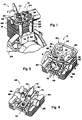
- Figures 1 through 7 show a small one-cylinder, four cycle engine 10 according to the present invention preferably having a displacement of between about 20 and 80 cubic centimeters.
- the engine 10 comprises a cylinder head assembly 12 and a piston 14 reciprocable in a cylinder block 16.
- the cylinder head assembly 12 includes a unitary, die cast aluminum cylinder head 48 adapted to cooperate with the cylinder block 16, and a rocker box 50.
- the rocker box 50 is also a unitary die cast aluminum or magnesium part, and is adapted to at least partially house the rocker arms 44 and 46.
- the rocker box 50 has a first pair of holes 52 therethrough adapted to receive means, such as bolts or rocker studs, for connecting the rocker box to the cylinder head 48.
- rocker studs 54 extend through the cylinder head 48 to secure the entire cylinder head assembly 12 to the cylinder block 16.
- the rocker box 50 also has a second pair of holes 56 therethrough adapted to respectively receive a pair of valve guides 58 and 60 projecting from the cylinder head 48.
- a third pair of holes 62 are formed in the rocker box 50 for receiving the push rods 38 and 40. If the rocker box is formed from aluminum, the holes 62 can be cast in a generally oval shape, as shown in Figure 3, to act as push rod guides. If the rocker box is formed from magnesium, stamped steel guide plates having generally oval holes therethrough are preferably added to act as push rod guides.
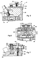
- the rocker box 50 is connected to the cylinder head 48 so as to define an air passage 64 therebetween through which cooling air may flow.
- the air passage 64 preferably extends between cross flow intake and exhaust ports 66 and 68, respectively, formed in the cylinder head 48.
- the cylinder head 48 has a plurality of cooling fins 70 which project into the air passage 64 between the cylinder head and the rocker box 50.
- a main cooling fin 72 projects rearwardly from a spark plug boss 74 and up into an expanding groove 76 formed in the bottom of the rocker box 50. All the cooling fins 70, including the main cooling fin 72, are aligned generally transversely to an imaginary line extending between the axes of the intake and exhaust valves 18 and 20.
- the cylinder head 48 also has drilled therein an exhaust gas recirculation (EGR) port 77.
- the EGR port extends between the innermost sections of the intake port 66 and the exhaust port 68, and generally below the air passage 64.
- the EGR port 77 is preferably generally coaxial with the exhaust port and offset slightly from the axis of the intake port as viewed from above, although this arrangement may be reversed.
- the EGR port 77 preferably has a constant circular cross-section with a diameter of about 1.25 millimeters. Throughout the range of engine operation, and in particular at the normal operational speed of about 7-8000 rpm, approximately 10% of the total exhaust gases produced by the engine are drawn back through the EGR port 77 to the intake port 66 for mixing with the incoming fuel-air mixture.
- a pair of elongated push rod tubes 78 and 80 in which push rods 38 and 40 are respectively reciprocable are integrally formed with the rocker box 50.
- the push rod tubes 78 and 80 extend, externally of the cylinder block 16, from the rocker box 50 to sealingly cooperate with the valve drive chamber 34 of the crankcase 24.
- Both the cylinder head 48 and the rocker box 50 also have a plurality of horizontal cooling fins 82 disposed at least partially around their perimeters, preferably proximate the intake and exhaust ports 66 and 68 and adjacent the push rod tubes 78 and 80. Because the cylinder head and the rocker box of the present invention are discrete components that can be separately cast, the cylinder head assembly has relatively uniform wall thicknesses throughout, which facilitates engine cooling.
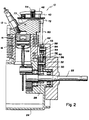
- the pin forming the camshaft 32 and a generally parallel pin forming a follower shaft 84 extend from a bracket or base member 86 to comprise a carrier 88.
- the base member 86 is preferably formed as an alloy steel powdered metal part.
- the cam gear 30 and the cam 36 which are preferably formed as a unitary powdered metal part, are rotatably supported on the camshaft 32.
- the followers 42 and 43 are rotatably supported on the follower shaft 84.
- the carrier 88, cam gear 30 and cam 36, and the followers 42 and 43 comprise a cam tower assembly.
- the shafts 32 and 84 extend from a common base member 86, rather than being secured separately to the cylinder block and/or the crankcase, the distance between the shafts is more closely controllable. This eliminates the assembly and tolerance problems involved in the conventional method of assembly where the cam and the follower are assembled as individual components on separate pins on the crankcase and the cylinder assembly, respectively. The present construction also eliminates potential oil leak areas often found in conventional designs where the walls were drilled to accept the pins therethrough.
- the cam tower assembly is preferably attached to the engine by means of two bolts or socket head screws 90 extending through open grooves in the base member 86 and into the crankcase 24.
- the crankcase can be either cored or drilled and tapped to accept the screws.
- This structure makes the cam tower assembly easily serviceable because with the removal of only the screws 90, the entire assembly can be removed from the cranckcase. While the cam tower assembly is shown in Figure 2 with the base member 86 proximate the flywheel and the cam gear 30 proximate the cylinder block, it should be appreciated that a mirror image of this arrangement with the base member proximate the cylinder block and the cam gear proximate the flywheel is equally feasible.
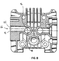
- Figure 8 shows that the axis 92 of the horizontal portion 94 of the intake port 66 is not aligned with the axis 96 of the vertical portion 98 of the intake port. Because of this offset intake port feature, the incoming fuel-air mixture is deflected or pre-swirled by the wall of the vertical portion 98 of the intake port around the stem of the intake valve, and continues to swirl as it is introduced into the combustion chamber. The swirling mixture thus created burns more quickly and/or completely when subsequently ignited by the spark plug.
- the intake port can be offset below the horizontal axis of the intake port so as to create a counterclockwise swirl.
Landscapes
- Engineering & Computer Science (AREA)
- Chemical & Material Sciences (AREA)
- Combustion & Propulsion (AREA)
- Mechanical Engineering (AREA)
- General Engineering & Computer Science (AREA)
- Valve-Gear Or Valve Arrangements (AREA)
- Cylinder Crankcases Of Internal Combustion Engines (AREA)
Applications Claiming Priority (3)
| Application Number | Priority Date | Filing Date | Title |
|---|---|---|---|
| US97075 | 1993-07-23 | ||
| US08/097,075 US5421292A (en) | 1993-07-23 | 1993-07-23 | Cylinder head assembly |
| EP94922489A EP0708884B1 (de) | 1993-07-23 | 1994-07-06 | Zylinderkopfzusammenbau |
Related Parent Applications (1)
| Application Number | Title | Priority Date | Filing Date |
|---|---|---|---|
| EP94922489A Division EP0708884B1 (de) | 1993-07-23 | 1994-07-06 | Zylinderkopfzusammenbau |
Publications (3)
| Publication Number | Publication Date |
|---|---|
| EP0940573A2 true EP0940573A2 (de) | 1999-09-08 |
| EP0940573A3 EP0940573A3 (de) | 1999-10-27 |
| EP0940573B1 EP0940573B1 (de) | 2004-02-11 |
Family
ID=22260846
Family Applications (2)
| Application Number | Title | Priority Date | Filing Date |
|---|---|---|---|
| EP99202215A Expired - Lifetime EP0940573B1 (de) | 1993-07-23 | 1994-07-06 | Zylinderkopfzusammenbau |
| EP94922489A Expired - Lifetime EP0708884B1 (de) | 1993-07-23 | 1994-07-06 | Zylinderkopfzusammenbau |
Family Applications After (1)
| Application Number | Title | Priority Date | Filing Date |
|---|---|---|---|
| EP94922489A Expired - Lifetime EP0708884B1 (de) | 1993-07-23 | 1994-07-06 | Zylinderkopfzusammenbau |
Country Status (6)
| Country | Link |
|---|---|
| US (2) | US5421292A (de) |
| EP (2) | EP0940573B1 (de) |
| JP (1) | JPH09502235A (de) |
| AU (1) | AU7358094A (de) |
| DE (2) | DE69422987T2 (de) |
| WO (1) | WO1995003485A1 (de) |
Families Citing this family (42)
| Publication number | Priority date | Publication date | Assignee | Title |
|---|---|---|---|---|
| EP1471229A1 (de) * | 1995-07-06 | 2004-10-27 | Tecumseh Products Company | Brennkraftmaschine mit obenliegender Nockenwelle und trockener Ölwanne |
| US5638779A (en) * | 1995-08-16 | 1997-06-17 | Northrop Grumman Corporation | High-efficiency, low-pollution engine |
| US5657729A (en) * | 1995-08-16 | 1997-08-19 | Northrop Grumman Corporation | Fiber reinforced ceramic matrix composite cylinder head and cylinder head liner for an internal combustion engine |
| US6047678A (en) * | 1996-03-08 | 2000-04-11 | Ryobi North America, Inc. | Multi-position operator-carried four-cycle engine |
| US6039020A (en) | 1998-03-05 | 2000-03-21 | Ryobi Outdoor Products, Inc. | Multiple-position, operator-carried, four-stroke engine |
| US5983849A (en) * | 1998-03-17 | 1999-11-16 | S & S Cycle, Inc. | Composite pushrod hole adapter plate for internal combustion engines |
| US6065457A (en) | 1998-06-30 | 2000-05-23 | Harley-Davidson Motor Company | Breather assembly for an internal combustion engine |
| US6296071B1 (en) | 1998-06-30 | 2001-10-02 | Harley-Davidson Motor Company Group, Inc. | Motorcycle rocker assembly |
| USD500768S1 (en) | 1999-07-27 | 2005-01-11 | Keith A. Brinton | Portion of a motorcycle cylinder head |
| WO2001007771A1 (en) * | 1999-07-27 | 2001-02-01 | Brinton Keith A | Engine cooling system and method for making same |
| BG63607B1 (bg) * | 1999-08-02 | 2002-06-28 | Георги ГЪЛЪБОВ | Двигател с вътрешно горене |
| US6484683B2 (en) | 2000-01-26 | 2002-11-26 | International Engine Intellectual Property Company, L.L.C. | Rocker carrier |
| US6499453B1 (en) | 2000-10-30 | 2002-12-31 | Tecumseh Products Company | Mid cam engine |
| JP4545361B2 (ja) | 2001-09-18 | 2010-09-15 | 株式会社やまびこ | 4サイクル内燃機関用冷却装置 |
| US20030213441A1 (en) * | 2002-06-03 | 2003-11-20 | Brinton Keith A. | Engine cooling system and method for making same |
| US6739304B2 (en) * | 2002-06-28 | 2004-05-25 | Kohler Co. | Cross-flow cylinder head |
| JP2004270632A (ja) * | 2003-03-11 | 2004-09-30 | Yanmar Co Ltd | エンジンの排気還流装置 |
| US20050066916A1 (en) * | 2003-09-25 | 2005-03-31 | Cordy Clifford B. | Axial flow cooling for air-cooled engines |
| US7617804B2 (en) * | 2003-09-25 | 2009-11-17 | Cordy Jr Clifford B | Axial flow cooling for air-cooled engines |
| US7246610B2 (en) * | 2003-10-07 | 2007-07-24 | S & S Cycle, Inc. | Cylinder head |
| USD514035S1 (en) | 2003-11-12 | 2006-01-31 | Midwest Motorcycle Supply | Rocker box |
| US6883483B1 (en) * | 2003-11-20 | 2005-04-26 | Dresser, Inc. | Gasket with pushrod retainer |
| US6883505B1 (en) | 2004-04-02 | 2005-04-26 | Midwest Motorcycle Supply | Rocker box assembly with reed valve |
| US20050252471A1 (en) * | 2004-05-14 | 2005-11-17 | S & S Cycle, Inc. | Twin cylinder motorcycle engine |
| US7063078B2 (en) * | 2004-06-30 | 2006-06-20 | Harley-Davidson Motor Company Group, Inc. | Breather assembly for an internal combustion engine |
| US7086367B2 (en) * | 2004-08-17 | 2006-08-08 | Briggs & Stratton Corporation | Air flow arrangement for a reduced-emission single cylinder engine |
| US7341027B2 (en) * | 2006-01-20 | 2008-03-11 | Makita Numazu Corporation | Portable 4-cycle engine and portable machine equipped with the 4-cycle engine |
| US7975381B2 (en) * | 2008-09-10 | 2011-07-12 | Ford Global Technologies | Valve operating camshaft system for internal combustion engine |
| US8220429B2 (en) * | 2009-07-23 | 2012-07-17 | Briggs & Stratton Corporation | Overhead valve and rocker arm configuration for a small engine |
| US8251030B2 (en) * | 2009-07-23 | 2012-08-28 | Briggs & Stratton Corporation | Rocker cover system |
| DE102012023836B4 (de) * | 2012-12-06 | 2022-07-07 | Man Energy Solutions Se | Brennkraftmaschine in Baukastenbauform |
| US9109271B2 (en) | 2013-03-14 | 2015-08-18 | Brunswick Corporation | Nickel containing hypereutectic aluminum-silicon sand cast alloy |
| US10370742B2 (en) | 2013-03-14 | 2019-08-06 | Brunswick Corporation | Hypereutectic aluminum-silicon cast alloys having unique microstructure |
| US9650699B1 (en) | 2013-03-14 | 2017-05-16 | Brunswick Corporation | Nickel containing hypereutectic aluminum-silicon sand cast alloys |
| US9103301B2 (en) | 2013-07-23 | 2015-08-11 | Midwest Motorcycle Supply Distributors Corp. | Exhaust gas recirculation system for a motorcycle engine |
| USD753186S1 (en) | 2014-05-06 | 2016-04-05 | Champion Engine Technology, LLC | Internal combustion engine cylinder head |
| USD736832S1 (en) | 2014-05-06 | 2015-08-18 | Champion Engine Technology, LLC | Internal combustion engine |
| US10018081B2 (en) * | 2014-05-06 | 2018-07-10 | Champion Engine Technology, LLC | Engine cylinder head push rod tube configuration |
| CN105952532A (zh) * | 2016-04-22 | 2016-09-21 | 安庆中船动力配套有限公司 | 一种单缸无曲轴式活塞发动机 |
| WO2018170228A1 (en) | 2017-03-16 | 2018-09-20 | Cummins Inc. | Block mounted overhead cam support system for internal combustion engines |
| US20190390628A1 (en) * | 2018-06-25 | 2019-12-26 | Leading Edge V-Twin LLC | Methods and apparatus for an actively cooled cylinder block |
| US11692503B2 (en) | 2020-12-07 | 2023-07-04 | Ford Global Technologies, Llc | Methods and systems for an engine with removable camshaft carrier |
Family Cites Families (23)
| Publication number | Priority date | Publication date | Assignee | Title |
|---|---|---|---|---|
| US1415374A (en) * | 1916-06-08 | 1922-05-09 | Ralph M Lovejoy | Internal-combustion engine |
| US1458223A (en) * | 1918-02-07 | 1923-06-12 | Albert Y Edwards | Valve mechanism for internal-combustion engines |
| US1874338A (en) * | 1929-09-18 | 1932-08-30 | Continental Aircraft Engine Co | Rocker box housing |
| FR900899A (fr) * | 1942-12-31 | 1945-07-11 | Porsche Kg | Culasse de cylindre pour moteurs à combustion interne à refroidissement par air |
| US2529616A (en) * | 1947-07-09 | 1950-11-14 | Frank H Roeder | Rocker arm cover vapor receiver |
| CH352185A (de) * | 1957-08-14 | 1961-02-15 | Lanova Ag | Ventilsteuerung für Brennkraftmaschinen |
| US2970584A (en) * | 1958-10-24 | 1961-02-07 | Kloeckner Humboldt Deutz Ag | Valve control for internal combustion engines |
| US3064634A (en) * | 1959-08-24 | 1962-11-20 | Theodore C Tyce | Light weight engine |
| JPS5392056A (en) * | 1977-01-24 | 1978-08-12 | Kubota Ltd | Forced lubricating apparatus of forced air-cooled overhead valve engine |
| US4345552A (en) * | 1979-12-18 | 1982-08-24 | Cummins Engine Company, Inc. | Rocker housing and rocker cover |
| US4404936A (en) * | 1980-04-30 | 1983-09-20 | Mitsubishi Jukogyo Kabushiki Kaisha | Breather device for overhead valve engines |
| JPS5949755U (ja) * | 1982-09-27 | 1984-04-02 | 本田技研工業株式会社 | 内燃エンジン |
| JPS6125962A (ja) * | 1984-07-13 | 1986-02-05 | Kubota Ltd | エンジンの吸気通路への排気ガス還流装置 |
| US4554893A (en) * | 1984-10-01 | 1985-11-26 | General Motors Corporation | Lightweight engine |
| US4662322A (en) * | 1984-11-26 | 1987-05-05 | Kawasaki Jukogyo Kabushiki Kaisha | Overhead-valve engine |
| US4821694A (en) * | 1985-04-15 | 1989-04-18 | Brunswick Corporation | Hypereutectic aluminum-silicon casting alloy |
| JPS61241411A (ja) * | 1985-04-18 | 1986-10-27 | Honda Motor Co Ltd | Sohc型内燃機関における動弁装置 |
| US4601267A (en) * | 1985-07-26 | 1986-07-22 | Tecumseh Products Company | Valve mechanism lubrication system for an overhead valve engine |
| JPS6341614A (ja) * | 1986-08-08 | 1988-02-22 | Kawasaki Heavy Ind Ltd | 頭上弁エンジンの潤滑装置 |
| US4881496A (en) * | 1988-05-20 | 1989-11-21 | Tecumseh Products Company | Valve mechanism lubrication system for horizontal cylinder overhead valve engine |
| DE3900033A1 (de) * | 1989-01-02 | 1990-07-19 | Helmut R W Wittmann | Kraft- und arbeitsmaschine mit verdraengerwirkung |
| DE4139411C2 (de) * | 1990-11-30 | 1998-12-17 | Ryobi Ltd | Tragbares Arbeitsgerät, insbesondere Rasenmäher |
| US5058542A (en) * | 1991-01-28 | 1991-10-22 | Briggs & Stratton Corporation | Rocker box cover assembly for internal combustion engine |
-
1993
- 1993-07-23 US US08/097,075 patent/US5421292A/en not_active Expired - Lifetime
-
1994
- 1994-07-06 JP JP7505165A patent/JPH09502235A/ja active Pending
- 1994-07-06 AU AU73580/94A patent/AU7358094A/en not_active Abandoned
- 1994-07-06 DE DE69422987T patent/DE69422987T2/de not_active Expired - Lifetime
- 1994-07-06 DE DE69433553T patent/DE69433553T2/de not_active Expired - Lifetime
- 1994-07-06 EP EP99202215A patent/EP0940573B1/de not_active Expired - Lifetime
- 1994-07-06 EP EP94922489A patent/EP0708884B1/de not_active Expired - Lifetime
- 1994-07-06 WO PCT/US1994/007548 patent/WO1995003485A1/en not_active Ceased
-
1995
- 1995-06-06 US US08/470,934 patent/US5564374A/en not_active Expired - Lifetime
Also Published As
| Publication number | Publication date |
|---|---|
| DE69433553D1 (de) | 2004-03-18 |
| US5421292A (en) | 1995-06-06 |
| DE69422987T2 (de) | 2000-06-15 |
| DE69433553T2 (de) | 2004-12-23 |
| EP0708884A1 (de) | 1996-05-01 |
| EP0708884A4 (de) | 1996-11-06 |
| EP0940573B1 (de) | 2004-02-11 |
| US5564374A (en) | 1996-10-15 |
| DE69422987D1 (de) | 2000-03-16 |
| JPH09502235A (ja) | 1997-03-04 |
| EP0940573A3 (de) | 1999-10-27 |
| EP0708884B1 (de) | 2000-02-09 |
| AU7358094A (en) | 1995-02-20 |
| WO1995003485A1 (en) | 1995-02-02 |
Similar Documents
| Publication | Publication Date | Title |
|---|---|---|
| EP0940573B1 (de) | Zylinderkopfzusammenbau | |
| EP0567037B1 (de) | Luftgekühlte Vier-Takt-Brennkraftmaschine | |
| US5598820A (en) | Cylinder head for four stroke internal combustion engine | |
| EP1135585B1 (de) | Brennkraftmaschine mit kurbelgehäusespülung | |
| JPH0719106A (ja) | 4サイクルエンジンの冷却構造 | |
| JP2000120422A (ja) | エンジンのカム軸潤滑構造 | |
| US6431159B2 (en) | Oil separator structure of internal combustion engine | |
| US10975764B2 (en) | Opposed-piston internal combustion engine | |
| JPH07197848A (ja) | 多気筒エンジンのシリンダヘッド | |
| AU3971889A (en) | Low profile internal combustion engine | |
| EP0971116B1 (de) | Brennkraftmaschine | |
| JPH11166449A (ja) | 4サイクルエンジン | |
| US20100326379A1 (en) | Narrow profile horizontally-opposed engine | |
| JP4477537B2 (ja) | モノブロック型エンジン | |
| JP2002339724A (ja) | エンジンのブリーザ構造 | |
| JP2005139926A (ja) | 2サイクルエンジン | |
| JP2000034924A (ja) | 2サイクル内燃エンジン | |
| JPH04164105A (ja) | 減速出力形ohc式エンジン | |
| JP2000034927A (ja) | 2サイクル内燃エンジン | |
| JPH0351897B2 (de) | ||
| JPS6337490Y2 (de) | ||
| JP2516760B2 (ja) | エンジンにおける点火プラグ取付装置 | |
| JP3355778B2 (ja) | カムキャリア付きシリンダヘッド | |
| JPH0366498B2 (de) | ||
| JP2000220519A (ja) | Ohc型空冷エンジン |
Legal Events
| Date | Code | Title | Description |
|---|---|---|---|
| PUAI | Public reference made under article 153(3) epc to a published international application that has entered the european phase |
Free format text: ORIGINAL CODE: 0009012 |
|
| AC | Divisional application: reference to earlier application |
Ref document number: 708884 Country of ref document: EP |
|
| AK | Designated contracting states |
Kind code of ref document: A2 Designated state(s): DE FR GB IT |
|
| PUAL | Search report despatched |
Free format text: ORIGINAL CODE: 0009013 |
|
| AK | Designated contracting states |
Kind code of ref document: A3 Designated state(s): DE FR GB IT |
|
| 17P | Request for examination filed |
Effective date: 20000425 |
|
| AKX | Designation fees paid |
Free format text: DE FR GB IT |
|
| 17Q | First examination report despatched |
Effective date: 20010214 |
|
| GRAH | Despatch of communication of intention to grant a patent |
Free format text: ORIGINAL CODE: EPIDOS IGRA |
|
| GRAS | Grant fee paid |
Free format text: ORIGINAL CODE: EPIDOSNIGR3 |
|
| GRAA | (expected) grant |
Free format text: ORIGINAL CODE: 0009210 |
|
| RAP1 | Party data changed (applicant data changed or rights of an application transferred) |
Owner name: MTD PRODUCTS, INC. |
|
| AC | Divisional application: reference to earlier application |
Ref document number: 0708884 Country of ref document: EP Kind code of ref document: P |
|
| AK | Designated contracting states |
Kind code of ref document: B1 Designated state(s): DE FR GB IT |
|
| REG | Reference to a national code |
Ref country code: GB Ref legal event code: FG4D |
|
| REF | Corresponds to: |
Ref document number: 69433553 Country of ref document: DE Date of ref document: 20040318 Kind code of ref document: P |
|
| ET | Fr: translation filed | ||
| PLBE | No opposition filed within time limit |
Free format text: ORIGINAL CODE: 0009261 |
|
| STAA | Information on the status of an ep patent application or granted ep patent |
Free format text: STATUS: NO OPPOSITION FILED WITHIN TIME LIMIT |
|
| 26N | No opposition filed |
Effective date: 20041112 |
|
| PGFP | Annual fee paid to national office [announced via postgrant information from national office to epo] |
Ref country code: GB Payment date: 20060705 Year of fee payment: 13 |
|
| GBPC | Gb: european patent ceased through non-payment of renewal fee |
Effective date: 20070706 |
|
| PG25 | Lapsed in a contracting state [announced via postgrant information from national office to epo] |
Ref country code: GB Free format text: LAPSE BECAUSE OF NON-PAYMENT OF DUE FEES Effective date: 20070706 |
|
| PGFP | Annual fee paid to national office [announced via postgrant information from national office to epo] |
Ref country code: IT Payment date: 20080731 Year of fee payment: 15 |
|
| PGFP | Annual fee paid to national office [announced via postgrant information from national office to epo] |
Ref country code: FR Payment date: 20090710 Year of fee payment: 16 |
|
| PGFP | Annual fee paid to national office [announced via postgrant information from national office to epo] |
Ref country code: DE Payment date: 20100630 Year of fee payment: 17 |
|
| PG25 | Lapsed in a contracting state [announced via postgrant information from national office to epo] |
Ref country code: IT Free format text: LAPSE BECAUSE OF NON-PAYMENT OF DUE FEES Effective date: 20090706 |
|
| REG | Reference to a national code |
Ref country code: FR Ref legal event code: ST Effective date: 20110331 |
|
| PG25 | Lapsed in a contracting state [announced via postgrant information from national office to epo] |
Ref country code: FR Free format text: LAPSE BECAUSE OF NON-PAYMENT OF DUE FEES Effective date: 20100802 |
|
| PG25 | Lapsed in a contracting state [announced via postgrant information from national office to epo] |
Ref country code: DE Free format text: LAPSE BECAUSE OF NON-PAYMENT OF DUE FEES Effective date: 20120201 |
|
| REG | Reference to a national code |
Ref country code: DE Ref legal event code: R119 Ref document number: 69433553 Country of ref document: DE Effective date: 20120201 |