EP0939533A2 - Couvercle coulissant pour une unité de communication - Google Patents
Couvercle coulissant pour une unité de communication Download PDFInfo
- Publication number
- EP0939533A2 EP0939533A2 EP99301466A EP99301466A EP0939533A2 EP 0939533 A2 EP0939533 A2 EP 0939533A2 EP 99301466 A EP99301466 A EP 99301466A EP 99301466 A EP99301466 A EP 99301466A EP 0939533 A2 EP0939533 A2 EP 0939533A2
- Authority
- EP
- European Patent Office
- Prior art keywords
- slide
- slide assembly
- communication unit
- housing
- tracks
- Prior art date
- Legal status (The legal status is an assumption and is not a legal conclusion. Google has not performed a legal analysis and makes no representation as to the accuracy of the status listed.)
- Granted
Links
Images


Classifications
-
- H—ELECTRICITY
- H04—ELECTRIC COMMUNICATION TECHNIQUE
- H04M—TELEPHONIC COMMUNICATION
- H04M1/00—Substation equipment, e.g. for use by subscribers
- H04M1/02—Constructional features of telephone sets
- H04M1/0202—Portable telephone sets, e.g. cordless phones, mobile phones or bar type handsets
- H04M1/0206—Portable telephones comprising a plurality of mechanically joined movable body parts, e.g. hinged housings
- H04M1/0208—Portable telephones comprising a plurality of mechanically joined movable body parts, e.g. hinged housings characterized by the relative motions of the body parts
- H04M1/0235—Slidable or telescopic telephones, i.e. with a relative translation movement of the body parts; Telephones using a combination of translation and other relative motions of the body parts
- H04M1/0237—Sliding mechanism with one degree of freedom
-
- H—ELECTRICITY
- H04—ELECTRIC COMMUNICATION TECHNIQUE
- H04M—TELEPHONIC COMMUNICATION
- H04M1/00—Substation equipment, e.g. for use by subscribers
- H04M1/72—Mobile telephones; Cordless telephones, i.e. devices for establishing wireless links to base stations without route selection
- H04M1/725—Cordless telephones
Definitions
- the invention relates to a communication unit having a housing part provided with means for entering information, and a slide cover slidable relatively to the housing part. In one position the slide cover will at least partly cover the means for entering information, while said means are freely accessible in another position of the slide cover.
- a communication unit having a housing part provided with a set of tracks along which a slide assembly is slidable relatively to the housing part, and said slide assembly includes a cover part and a set of rod-shaped sliding rails extending from said cover part in the sliding direction for being received in said set of tracks on the housing part. It is hereby ensured that a substantial part of the slide rail will remain in the track even when the slide is fully extended. This makes it easier to control the force required to move the slide.
- the sliding rails will be slightly curved and substantially the entire length of the rails will be received in the corresponding tracks on the main body of the communication unit.
- the track on the outer side of the main body of the communication unit terminates in channels continuing in tracks internally in the main body of the communication unit.
- the invention provides a communication unit having a slide cover which, in an open position of the slide, allows improved access to the information input means and still provides a good mechanical connection between the slide and the main body of the unit.
- the slide assembly comprises the cover part which at least partly covers said means for entering information in one position of said slide assembly, and a slide part carrying said set of sliding rails.
- These two parts may be provided as an injection moulded plastics item, and as a punched and/or bent sheet metal item, respectively. By using the inherent resilient properties of the items, these parts may advantageously be snapped together.
- the resilient connector legs are integrated in a connector comprising a carrier structure carrying a set of telescopic legs.
- the carrier structure is used for fixing the connector relatively to the housing of the communication unit.
- Each of the telescopic legs comprises a tip part biased to an extended position by basing means, e.g. formed as springs internally in the legs. A reliable connection with said set of conducting paths for the microphone is obtain hereby.
- the communication unit may furthermore comprise a slide release mechanism including a biased mechanism for moving the slide assembly to a position in which the means for entering information are accessible, and a release mechanism for activating said biased mechanism.
- the biased mechanism co-operates with at least one of said set of sliding rails extending from said cover part.
- the slide release mechanism includes a guide profile along which said at least one sliding rail is movable, a traveller fixed to said at least one sliding rail and guided by the guide profile, means for biasing the traveller in a position in which the cover part at least partly covers said means for entering information, and locking means for locking the traveller in this position.
- the locking means includes a push button pivotally attached to one end of the guide profile and extending through the housing wall, a resilient latch spring fixed to the same end of the guide profile and engaging the traveller, and said push button is provided with a pin acting on the resilient latch spring for releasing the traveller when the push button is pressed.
- the biasing means includes a coil spring aligned with said at least one sliding rail and having one end attached to the traveller and the other end attached to the housing of the communication unit.
- the communication unit includes means for disabling the information entering means, e.g. disabling the key of a keypad.
- the disabling means includes a key for confirming an activity suggested in a display of the communication unit.
- the communication unit detects that the slide has been moved to a closed position, the disabling means suggests disabling the means for entering information.
- the means for entering information are disabled if the user confirms the suggestion by pressing the key.
- the key is a soft key and the functionality of the sort key will change to an idle mode functionality after a time-out period when the action has not been accepted.
- the invention furthermore relates to a front cover for a communication unit, said front cover including a housing part through which means for entering information may be accessed, and a slide assembly.
- the housing part is provided with a set of tracks along which the slide assembly is slidable relatively to the housing part.
- the slide assembly includes a cover part, and a set of rod-shaped sliding rails extends from said cover part in the sliding direction for being received in said set of tracks on the housing part.
- a communication unit in accordance with the invention will be described in a first aspect with reference to a hand portable phone, preferably a cellular phone.
- a preferred embodiment of this phone is shown in Figures 1 and 2.
- the phone is shown with the slide in closed and open positions in Figures 1 and 2, respectively.
- the phone is provided with a front cover 2 having a window frame 3 encircling the protection window of the display assembly 1.
- the phone is provided with a slide cover 5 snapped onto a metal slide frame 6 sliding in slide tracks 7 (see Figure 3) in the front cover 2 along a keypad area and in extension thereof.
- the front cover 2 is provided with a plurality of openings, the largest one being an opening 4 in which the protection window 14 of the display assembly 1 is received.
- the front cover 2 is provided with sixteen openings through which the keys of a keypad 8 extend.
- a navigation key assembly 10 extends partly through the front cover 2 between the other keys and the display.
- the keypad 8, the navigation key assembly 10 and the display assembly 1 rest on and are electrically connected to a printed circuit board (PCB) 9 of the phone.
- a slide sensor switch 15 shown on an enlarged scale in Figure 6 is mounted in the bottom of the PCB 9.
- the microphone assembly mounted in the slide cover 5 has a pin that passes through an opening in the front cover 2 and closes the switch 14 when the slide is in closed position.
- An antenna 13 is mounted in the top corner of a back cover 11 and is connected to the RF circuit on the PCB 9.
- a spring based/latch based slide release mechanism 12 is included along one of the side walls of the back cover 11.
- the display assembly 1 forms the subject-matter of a separate UK patent application having the same filing date as the present application. This parallel patent application is hereby incorporated as a reference in the present application.
- Figure 10 schematically shows the most important parts of a preferred embodiment of the phone, said parts being essential to the understanding of the invention.
- the preferred embodiment of the phone of the invention is adapted for use in connection with the GSM network, but, of course, the invention may also be applied in connection with other phone networks, such as cellular networks and various forms of cordless phone systems or in dual band phones accessing sets of these systems/networks.
- the microphone 46 records the user's speech, and the analog signals formed thereby are A/D converted in an A/D converter (not shown) before the speech is encoded in an audio part 20.
- the encoded speech signal is transferred to the controller 18 (physical layer processor), which e.g. supports the GSM terminal software.
- the controller 18 is connected to the user interface. Thus, it is the controller 18 which monitors the activity in the phone and controls the display 1 in response thereto.
- a state change event may be caused by the user when he activates the keypad including the navigation key 10, and this type of events is called entry events or user events.
- the network in communication with the phone may cause a state change event.
- This type of events and other events beyond the user's control are called non user events.
- Non user events comprise status change during call set-up, change in battery voltage, change in antenna conditions, message on reception of SMS, etc.
- the slide assembly used in the phone shown in Figures 1 and 2 includes the slide cover 5 (shown in detail in Figure 4) snapped onto a metal slide frame 6 (shown in detail in Figure 5).
- the main surface of the slide cover 5 acts as an integrated part of the housing when the slide is in closed position.
- the slide cover 5 carries the microphone 46 of the phone according to the invention. Therefore, a number of orifices 43 are provided in a microphone chamber 46c on the slide cover for transmitting the sound toward the microphone 46.
- the microphone 46 is a part of a pre-assembled microphone assembly also including a microphone flex PCB 45 with components and a flex strip 44 with two gold tracks 44a (just partly shown) serving as wires for the microphone 46.
- the microphone assembly is adhered to the inner surface and a side wall 49 of the slide cover 5 by an appropriate adhesive.
- the microphone 46 is received in a rubber microphone gasket 47 absorbing the noise and the vibrations propagating in the slide cover 5.
- a protection cap 48 covers and protects the microphone 46 and the PCB 45 against external influences.
- the protection cap 48 is provided with two hooks 60 co-operating with the slide sensor switch 15 via an opening in the bottom of the front cover 2.
- the slide cover 5 is provided with side walls 49 around three sides fitting with the housing of the phone with the slide in closed position. Opposite to the microphone the slide cover 5 is provided with a recess or a depression 40 and with lug-shaped extensions 41 of the side walls 49. The inner side of these lug-shaped extensions 41 is provided with tracks or recesses 50 having respective locking pins 42. The resilient properties of the lugs 41 and the guiding and locking properties of the recesses 50, pins 52 and depression 40 provide a snap coupling between the slide cover 5 and the metal slide frame 6.
- the metal slide frame 6 is shown in Figure 5.
- a carrier part is formed by punching and forming sheet metal and includes a cover part 52, a lip 53 received in the depression 40 supporting the slide cover 5 and two uprights 54 with apertures receiving the pins 52 when assembled.
- the uprights 54 are received in the recesses 50.
- the two plungers or rails 51 are formed by extrusion, cut and bent before being placed in an assembly jig. Here, the rails 51 are joined with the uprights 54 by laser welding.
- Figure 6 shows a preferred embodiment of a slide sensor switch 15 which is positioned between the PCB 9 and the front cover 2 opposite to the antenna 13.
- a plastics body 55 provides the mechanical strength of the switch 15 and has fingers 58 holding the two conductors 56 and 57 of the switch 15.
- the conductors 56 and 57 are formed by punching and forming sheet metal to conform to the shape of the body 55, and both conductors are provided with a resilient spring parts 56a and 57a which, via loops, are terminated adjacent to each other.
- the switch constituted by the conductors 56 and 57 will be opened.
- the switch is closed (carrying a small current) with the slide in open position. This will be recognised by the controller 18, and the controller 18 may then control the UI in dependence on the slide position. Calls may be answered and terminated by opening and closing the slide.
- the functionality of the soft keys 8 and the navigation key 10 will also be changed by opening and closing the slide.
- the slide switch is adapted to deem the slide closed in the one end position and in a position up to e.g. 2 mm therefrom. In all other positions the slide will be handled as being in open position.
- Figure 7 shows a preferred embodiment of the microphone connector 22 which is position between the PCB 9 and the back cover 11 in the bottom of the phone.
- the microphone connector 22 comprises a plastics body 63 supporting two telescopic legs each having first and second tube-shaped members 64 and 67, respectively.
- the telescopic legs are biased toward an extended position - this is shown schematically in Figure 13.
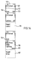
- Figure 13 Here it will be seen how the first member 64 may travel between two extreme positions, and how a coil spring 68 urges the member 64 toward one of said extreme position.
- the first members 64 have respective tips 65 sliding against the conducting part of the flex strip 44 when the slide is moved.
- the two telescopic legs are connected to the PCB 9 via respective resilient connectors 66a and 66b.
- the position of the microphone connector 22 is kept partly by mechanical mounting in the back cover 11, partly by fixing the connector 66a between a screw tower 69 of the back cover 11 and the PCB 9.
- the second connector 66b just establishes the contact by means of its resilient properties.
- the biased members 64 pass through respective openings 59 in the back cover 11.
- the slide release mechanism 12 is shown in detail in Figures 8 and 9.
- the slide release mechanism 12 acts as a biased mechanism for moving the slide into the open position in which the keypad 8 may be accessed.
- the movement of the slide is initiated by pressing a push button 70 which extends through an opening in the back cover 11 and activates a release mechanism.
- the biased mechanism includes a guide profile along which a traveller fixed to one of the sliding rails on the slide is movable.
- the traveller is connected to one end of a coil spring 89 acting as basing means for the traveller when the cover is in closed position.
- a resilient latch spring engages the traveller, but may be released by means of the push button 70.
- the latch spring has a resilient arm 81 and a hook 82, and the pin 72 of the push button 70 acts on the arm 81 through a cut 77 in the carrier area when the button 70 has been pressed.
- the traveller is movable along the guide profile, and the traveller has a clamp 86 for gripping the end of one of the rails 51.
- the rail 51 is received laterally in the clamp 86.
- the traveller has two holes 84 for receiving two traveller rivets 83 through a slot 76 in the guiding profile 74.
- the traveller has a tilted beam 85 cooperating with the hook 82 of the latch spring.
- the traveller has a hook 87 on which one eye of a coil spring 89 is attached.
- the other eye 91 of the coil spring 89 is attached to a hook mounted in the back cover 11 in the bottom of the phone.
- the conducting paths on the strip 44 extend in continuation of and at a distance from one of the sliding rails 51.
- the controller 18 When the controller 18 detects via the slide sensor 15 that the slide has been closed, it suggests to the user that one or more keys (preferably all of the keys) should be enabled.
- the first display is the idle mode display with the slide open.
- the top row on the display is an icon row 100 presenting some status icon.
- the name or the ID of the network operator is displayed, and two status bars 102 for the antenna strength and the battery level are displayed on each side of the main area, respectively.
- the current functionality of the soft keys 8 is displayed in associated parts 103 and 104 of a display.
- the functionalities are access to the phone book stored in the phone and to the menu structure of the phone, respectively.
- the display changes to the second display, and pressing the left soft key 8 will cause the keys to be locked or enabled. If the user presses the right soft key 8 or does not do anything for more than e.g. three seconds (time-out), the display will return to the idle mode display with the keys unlocked (enabled).
- the simplest way is to open the slide. In idle mode with locked keypad and closed slide the fourth display will be shown.
- the left soft key 8 will have an unlock functionality 104, and in order not to unlock by mistake the pressing of the left soft key 8 will cause the fifth display to be displayed, requiring a confirmation of the unlock request by pressing of the right soft key 8, too. This has to be done within a time-out of a duration of a few seconds. If the two soft keys are pressed successively within the time-out, the keypad is unlocked, and this is indicated in the sixth display with the "Keypad Active" text for a few seconds, and the idle mode display will be shown. Otherwise, the phone will show the fourth "Unlock" display.
Applications Claiming Priority (2)
| Application Number | Priority Date | Filing Date | Title |
|---|---|---|---|
| GB9804279 | 1998-02-27 | ||
| GB9804279A GB2334850A (en) | 1998-02-27 | 1998-02-27 | A communication device with a keyboard cover mounted upon sliding rods |
Publications (3)
| Publication Number | Publication Date |
|---|---|
| EP0939533A2 true EP0939533A2 (fr) | 1999-09-01 |
| EP0939533A3 EP0939533A3 (fr) | 2003-03-26 |
| EP0939533B1 EP0939533B1 (fr) | 2007-01-17 |
Family
ID=10827763
Family Applications (1)
| Application Number | Title | Priority Date | Filing Date |
|---|---|---|---|
| EP99301466A Expired - Lifetime EP0939533B1 (fr) | 1998-02-27 | 1999-02-26 | Couvercle coulissant pour une unité de communication |
Country Status (5)
| Country | Link |
|---|---|
| US (1) | US6370362B1 (fr) |
| EP (1) | EP0939533B1 (fr) |
| JP (1) | JPH11317583A (fr) |
| DE (1) | DE69934835T2 (fr) |
| GB (1) | GB2334850A (fr) |
Cited By (4)
| Publication number | Priority date | Publication date | Assignee | Title |
|---|---|---|---|---|
| FR2798799A1 (fr) * | 1999-09-22 | 2001-03-23 | Sagem | Telephone mobile comportant une vitre amovible |
| EP1860848A1 (fr) * | 2006-05-24 | 2007-11-28 | Nokia Corporation | Mécanisme coulissant d'un dispositif électronique comprenant un élément magnétique de décalage et un mécanisme d'actionnement opérant contre l'élément magnétique de décalage |
| US7414613B2 (en) | 2002-03-04 | 2008-08-19 | Nokia Corporation | Method for intermediate unlocking of a keypad on a mobile electronic device |
| EP2887623A1 (fr) * | 2013-12-20 | 2015-06-24 | Nokia Corporation | Appareil comprenant une partie de couverture pour un dispositif électronique |
Families Citing this family (84)
| Publication number | Priority date | Publication date | Assignee | Title |
|---|---|---|---|---|
| FI990890A (fi) * | 1999-04-21 | 2000-12-05 | Nokia Mobile Phones Ltd | Langaton viestin |
| JP4298054B2 (ja) * | 1999-04-23 | 2009-07-15 | パナソニック株式会社 | 携帯形無線装置 |
| US6560468B1 (en) | 1999-05-10 | 2003-05-06 | Peter V. Boesen | Cellular telephone, personal digital assistant, and pager unit with capability of short range radio frequency transmissions |
| US6542721B2 (en) | 1999-10-11 | 2003-04-01 | Peter V. Boesen | Cellular telephone, personal digital assistant and pager unit |
| GB2353170A (en) * | 1999-08-06 | 2001-02-14 | Nokia Mobile Phones Ltd | Slide assembly for a communication unit |
| GB2355127B (en) * | 1999-10-08 | 2004-04-21 | Nokia Mobile Phones Ltd | A portable device |
| US7508411B2 (en) * | 1999-10-11 | 2009-03-24 | S.P. Technologies Llp | Personal communications device |
| JP2001119457A (ja) * | 1999-10-15 | 2001-04-27 | Matsushita Electric Ind Co Ltd | 携帯電話装置 |
| JP2001251400A (ja) * | 2000-03-03 | 2001-09-14 | Matsushita Electric Ind Co Ltd | 携帯電話機 |
| JP4782970B2 (ja) * | 2000-06-30 | 2011-09-28 | パナソニック株式会社 | 携帯電話機 |
| US6898301B2 (en) * | 2000-07-10 | 2005-05-24 | Casio Computer Co., Ltd. | Authentication system based on fingerprint and electronic device employed for the system |
| US6600904B1 (en) * | 2000-09-12 | 2003-07-29 | Hong-Chun Wang | Structure of a bracket component for the press button of a mobile phone |
| US7454014B2 (en) * | 2000-12-29 | 2008-11-18 | Vertu Limited | Device with a loudspeaker and an ear piece cover |
| US7375973B2 (en) * | 2000-12-29 | 2008-05-20 | Vertu Limited | Casing for a communication device |
| FI20002897A (fi) * | 2000-12-29 | 2002-06-30 | Nokia Corp | Elektroninen laite ja välineet irrotettavan yksikön varmistamiseksi toiminta-asentoon |
| JP2002281134A (ja) * | 2001-03-16 | 2002-09-27 | Nec Corp | マイクユニット実装構造 |
| KR100417248B1 (ko) * | 2001-03-22 | 2004-02-05 | 에스케이텔레텍주식회사 | 슬라이드 모듈을 이용한 슬라이드 타입 휴대폰 |
| US6892081B1 (en) * | 2001-05-31 | 2005-05-10 | Nokia Corporation | Mobile terminal and method of operation using content sensitive menu keys in keypad locked mode |
| KR100663459B1 (ko) * | 2001-07-07 | 2007-01-02 | 삼성전자주식회사 | 폴더형 휴대 단말기에서 폴더의 교체형 슬라이딩 커버 장치 |
| WO2003019349A1 (fr) | 2001-08-25 | 2003-03-06 | Si Han Kim | Dispositif portable multi-affichage |
| JP2003179678A (ja) * | 2001-10-03 | 2003-06-27 | Nec Corp | 携帯電話機 |
| FI20012358A0 (fi) | 2001-11-30 | 2001-11-30 | Nokia Corp | Matkaviestinlaite ja menetelmä ohjelmistotoimintojen suorittamiseksi |
| US20030104850A1 (en) * | 2001-12-04 | 2003-06-05 | Cheng-Shing Lai | PDA with a protective cover for its display panel |
| KR100486611B1 (ko) * | 2001-12-18 | 2005-05-03 | 주식회사 팬택앤큐리텔 | 회전가능한 액정표시장치를 가지는 이동통신 단말기 |
| US6785565B2 (en) * | 2001-12-20 | 2004-08-31 | Nokia Corporation | Communications device having a sliding keypad cover |
| US20040162121A1 (en) * | 2002-02-19 | 2004-08-19 | Bamber Claire Elizabeth | Personal communication systems |
| JP2003298699A (ja) * | 2002-03-29 | 2003-10-17 | Nec Corp | スライド型携帯電話機 |
| JP4055116B2 (ja) | 2002-05-07 | 2008-03-05 | 日本電気株式会社 | 携帯電話機 |
| US6975889B2 (en) * | 2002-05-30 | 2005-12-13 | Quanta Computer Inc. | Cover-ejecting mechanism for a communication unit |
| US6847519B2 (en) * | 2002-06-28 | 2005-01-25 | Nokia Corporation | Phone with automatic linked qwerty keyboard |
| US7197140B2 (en) * | 2002-07-05 | 2007-03-27 | Asaro V Frank | Sound baffle for portable telephone handset |
| TW560785U (en) * | 2002-10-01 | 2003-11-01 | Toppoly Optoelectionics Corp | Cellular phone without opening a cover for communicating |
| JP2004135177A (ja) * | 2002-10-11 | 2004-04-30 | Sharp Corp | 携帯電話機 |
| JP3961397B2 (ja) * | 2002-10-29 | 2007-08-22 | 京セラ株式会社 | 携帯端末装置 |
| KR100506261B1 (ko) * | 2003-01-22 | 2005-08-10 | 삼성전자주식회사 | 휴대용 통신 장치 |
| JP2004235897A (ja) * | 2003-01-29 | 2004-08-19 | Kato Electrical Mach Co Ltd | 携帯電話機並びにスライド機構 |
| JP2004297417A (ja) * | 2003-03-27 | 2004-10-21 | Sanyo Electric Co Ltd | 携帯型無線端末機 |
| US7210629B2 (en) * | 2003-06-05 | 2007-05-01 | Samsung Electronics Co., Ltd. | Portable communication device |
| FI114950B (fi) * | 2003-06-24 | 2005-01-31 | Nokia Corp | Menetelmä päätelaitteen syöttö- ja näyttöosan visualisoimiseksi ja vastaava päätelaite |
| US20050054397A1 (en) * | 2003-09-08 | 2005-03-10 | Samsung Electronics Co., Ltd. | Portable sliding-type digital communication device and locking apparatus thereof |
| KR100563696B1 (ko) * | 2003-09-09 | 2006-03-28 | 엘지전자 주식회사 | 슬라이드형 이동통신 단말기의 슬라이드 구조 |
| JP3944506B2 (ja) | 2003-10-28 | 2007-07-11 | エルジー エレクトロニクス インコーポレイティド | スライド型携帯端末機及びそれに使用されるスライド装置 |
| KR100617690B1 (ko) * | 2003-11-10 | 2006-08-28 | 삼성전자주식회사 | 슬라이딩 타입 휴대용 무선 단말기 |
| KR100595614B1 (ko) * | 2003-11-18 | 2006-06-30 | 엘지전자 주식회사 | 휴대용 장치의 키눌림 방지방법 |
| WO2005067269A1 (fr) * | 2003-11-26 | 2005-07-21 | Sanyo Electric Co., Ltd. | Dispositif de communication mobile, procede permettant de commander un dispositif de communication mobile |
| WO2005076487A1 (fr) * | 2004-02-03 | 2005-08-18 | Jong Chul Choo | Glissiere permettant de relier la partie emettrice et la partie receptrice d'un telephone mobile de maniere coulissante |
| US7112082B2 (en) * | 2004-03-17 | 2006-09-26 | Wieson Technologies Co., Ltd. | Miniature memory card/SIM card dual-function connector |
| TWM259411U (en) * | 2004-06-11 | 2005-03-11 | Quanta Comp Inc | Automatic sliding mechanism |
| KR200362198Y1 (ko) * | 2004-06-18 | 2004-09-16 | 추종철 | 포고 핀 |
| CN101002180B (zh) | 2004-07-30 | 2012-09-05 | 捷讯研究有限公司 | 用于协调客户和主机安全模块的方法和系统 |
| US7784088B2 (en) * | 2004-07-30 | 2010-08-24 | Research In Motion Limited | Method and system for managing delayed user authentication |
| KR100628120B1 (ko) * | 2004-08-18 | 2006-09-26 | 엘지전자 주식회사 | 슬라이드타입 이동통신 단말기의 스프링장치 |
| JP2006074444A (ja) * | 2004-09-02 | 2006-03-16 | Advanex Inc | スライド装置及び携帯電話 |
| DE602005011788D1 (de) * | 2004-09-15 | 2009-01-29 | M2Sys Co Ltd | Schiebemechanismus zum öffnen und schliessen eines mobiltelefons |
| KR100689498B1 (ko) * | 2004-11-25 | 2007-03-02 | 삼성전자주식회사 | 슬라이딩 타입 휴대 단말기의 슬라이딩 모듈 |
| KR100617673B1 (ko) * | 2004-12-06 | 2006-08-28 | 삼성전자주식회사 | 슬라이딩 타입 휴대 단말기의 슬라이딩 모듈 및 이를채용하는 슬라이딩 타입 휴대 단말기 |
| US20070060219A1 (en) * | 2005-09-09 | 2007-03-15 | Hung-Chih Lin | Sliding shell |
| US8289687B2 (en) * | 2005-12-09 | 2012-10-16 | Marc Chase Weinstein | Multi-panel sliding cover for a device |
| US7860538B2 (en) * | 2006-02-28 | 2010-12-28 | Lg Electronics Inc. | Mobile terminal |
| US7996050B2 (en) * | 2006-02-28 | 2011-08-09 | Lg Electronics Inc. | Input device for an electronic device and electronic device having the same |
| US7764977B2 (en) * | 2006-05-24 | 2010-07-27 | Nokia Corporation | Memory card removal guard |
| KR101049035B1 (ko) * | 2006-05-26 | 2011-07-14 | 룸베르그 커넥트 게엠베하 | 휴대용 기기를 위한 슬라이딩 기구 |
| US20080074392A1 (en) * | 2006-09-25 | 2008-03-27 | Ahmed Mustafa | Lightguide subassembly for receiving a trackball navigational tool mountable within a handheld mobile device |
| WO2008063814A2 (fr) * | 2006-11-21 | 2008-05-29 | Motorola, Inc. | Procédé et système d'établissement d'un appel dans un réseau de communications |
| KR101315961B1 (ko) * | 2007-01-18 | 2013-10-08 | 엘지전자 주식회사 | 슬라이딩커버 구비 이동단말기 |
| US7967346B2 (en) * | 2007-07-30 | 2011-06-28 | Laird Technologies Korea Yh | Slider mechanisms for opening and closing portable terminals |
| JP4538483B2 (ja) | 2007-10-23 | 2010-09-08 | 株式会社カシオ日立モバイルコミュニケーションズ | 防水構造及び電子機器 |
| CN101426039A (zh) * | 2007-10-31 | 2009-05-06 | 鸿富锦精密工业(深圳)有限公司 | 便携式电子装置保护壳 |
| KR20090070215A (ko) * | 2007-12-27 | 2009-07-01 | 삼성전자주식회사 | 키패드 및 그를 구비한 슬라이드형 휴대 단말기 |
| US8295897B2 (en) * | 2008-02-08 | 2012-10-23 | Research In Motion Limited | Multi-function slide element for a mobile communication device |
| US20090209306A1 (en) * | 2008-02-19 | 2009-08-20 | Research In Motion Limited | Multi-function slide mechanism for a mobile communication device |
| TW200950691A (en) * | 2008-04-17 | 2009-12-01 | Laird Technologies Inc | EMI shielding slide assemblies for slidably opening and closing portable electronic devices and for providing EMI shielding for board-mounted electronic components |
| KR100961137B1 (ko) * | 2008-08-05 | 2010-06-09 | 삼성전기주식회사 | 이동통신 단말기 케이스 및 그 제조방법 |
| CN101350848B (zh) * | 2008-08-28 | 2011-03-30 | 苏州佳世达电通有限公司 | 电子装置 |
| TWI447559B (zh) * | 2008-11-07 | 2014-08-01 | Fih Hong Kong Ltd | 電池蓋結構 |
| CN101742857B (zh) * | 2008-11-14 | 2014-02-12 | 深圳富泰宏精密工业有限公司 | 电子装置 |
| CN101752536B (zh) * | 2008-12-18 | 2013-06-05 | 深圳富泰宏精密工业有限公司 | 电池固定装置 |
| JP5322320B2 (ja) * | 2011-07-12 | 2013-10-23 | パナソニック株式会社 | 電子機器 |
| CN202332674U (zh) | 2011-08-29 | 2012-07-11 | 华为终端有限公司 | 终端设备及其按键外壳和内壳体的模具 |
| TW201316888A (zh) * | 2011-10-07 | 2013-04-16 | Taer Inno Co Ltd | 行動通訊裝置保護框架 |
| JP2012059296A (ja) * | 2011-12-19 | 2012-03-22 | Kyocera Corp | 入力表示装置 |
| US9305538B2 (en) * | 2014-06-13 | 2016-04-05 | Alica Tyson | Transmission obscuring cover device |
| US9472917B2 (en) * | 2014-08-11 | 2016-10-18 | Apple Inc. | Internal component arrangement within a housing |
| US9632544B2 (en) | 2015-03-11 | 2017-04-25 | Microsoft Technology Licensing, Llc | Apparatus for receiving at least one integrated circuit card |
Citations (5)
| Publication number | Priority date | Publication date | Assignee | Title |
|---|---|---|---|---|
| EP0389676A2 (fr) * | 1989-03-31 | 1990-10-03 | Mitsubishi Denki Kabushiki Kaisha | Appareil de communication portatif |
| WO1994013088A1 (fr) * | 1992-12-02 | 1994-06-09 | Motorola Inc. | Ensemble boitier pour dispositif de communication sans fil |
| DE4307164A1 (de) * | 1993-03-06 | 1994-09-08 | Constin Design Gmbh | Schnurloses, mobiles Telefon |
| EP0726657A1 (fr) * | 1994-08-31 | 1996-08-14 | Sony Corporation | Terminal de transmission |
| GB2310561A (en) * | 1996-02-26 | 1997-08-27 | Nokia Mobile Phones Ltd | Mobile telephone keys usable for a range of positions of a sliding cover |
Family Cites Families (22)
| Publication number | Priority date | Publication date | Assignee | Title |
|---|---|---|---|---|
| US4845772A (en) | 1988-06-13 | 1989-07-04 | Motorola, Inc. | Portable radiotelephone with control switch disabling |
| DE3836406A1 (de) | 1988-10-26 | 1990-05-03 | Bosch Gmbh Robert | Handapparatfoermiges funkbedienteil |
| GB2235606B (en) * | 1989-08-24 | 1994-03-30 | Technophone Ltd | Portable telephone |
| AU9100091A (en) * | 1990-11-16 | 1992-06-11 | Universal Cellular, Inc. | Portable telephone housing |
| JP2689785B2 (ja) * | 1991-09-30 | 1997-12-10 | 日本電気株式会社 | 小型携帯無線機 |
| DE4202383C2 (de) | 1992-01-29 | 1994-03-24 | Loewe Opta Gmbh | Handsprechfunkgerät |
| JPH0661910A (ja) * | 1992-04-21 | 1994-03-04 | Nec Corp | 携帯電話装置 |
| JPH0645982A (ja) | 1992-07-22 | 1994-02-18 | Sony Corp | 携帯型無線電話機 |
| JP2595932B2 (ja) | 1994-05-18 | 1997-04-02 | 日本電気株式会社 | 携帯無線機 |
| FR2738985B1 (fr) * | 1995-09-14 | 1997-10-17 | Alcatel Mobile Comm France | Terminal de radiocommunication agence pour recevoir un capot de protection |
| DE69738856D1 (de) * | 1996-02-26 | 2008-09-04 | Nokia Corp | Verfahren zur Bedienung eines Funktelefons |
| GB2310560B (en) * | 1996-02-26 | 2000-07-12 | Nokia Mobile Phones Ltd | A radio telephone |
| JP3606498B2 (ja) * | 1996-04-26 | 2005-01-05 | 三菱電機株式会社 | 携帯情報端末装置 |
| US6073027A (en) * | 1996-08-29 | 2000-06-06 | Bellsouth Corporation | Portable radiotelephone with sliding cover and automatic antenna extension |
| US5748454A (en) * | 1996-09-09 | 1998-05-05 | Motorola, Inc. | Battery clip assembly for a communication device |
| US5896277A (en) * | 1996-12-12 | 1999-04-20 | Motorola, Inc. | Slidable cover for a battery housing |
| JPH10224253A (ja) * | 1997-02-10 | 1998-08-21 | Sony Corp | 携帯通信機 |
| US5999822A (en) * | 1997-03-14 | 1999-12-07 | Sony Corporation | Cellular telephone with extendible microphone |
| US6128475A (en) * | 1997-04-04 | 2000-10-03 | Sony Corporation | Wireless telephone with sliding keyboard |
| US6002945A (en) * | 1997-05-05 | 1999-12-14 | Mcduffee; Dennis | Combination pager and cellular telephone having extensible, flexible mouthpiece |
| US5956398A (en) * | 1997-07-11 | 1999-09-21 | Ericsson Inc. | Telephone switching mechanism |
| JP3160714B2 (ja) * | 1998-07-08 | 2001-04-25 | 株式会社シコー技研 | 携帯無線通信機 |
-
1998
- 1998-02-27 GB GB9804279A patent/GB2334850A/en not_active Withdrawn
-
1999
- 1999-02-26 JP JP11049728A patent/JPH11317583A/ja active Pending
- 1999-02-26 DE DE69934835T patent/DE69934835T2/de not_active Expired - Lifetime
- 1999-02-26 EP EP99301466A patent/EP0939533B1/fr not_active Expired - Lifetime
- 1999-02-26 US US09/259,102 patent/US6370362B1/en not_active Expired - Lifetime
Patent Citations (5)
| Publication number | Priority date | Publication date | Assignee | Title |
|---|---|---|---|---|
| EP0389676A2 (fr) * | 1989-03-31 | 1990-10-03 | Mitsubishi Denki Kabushiki Kaisha | Appareil de communication portatif |
| WO1994013088A1 (fr) * | 1992-12-02 | 1994-06-09 | Motorola Inc. | Ensemble boitier pour dispositif de communication sans fil |
| DE4307164A1 (de) * | 1993-03-06 | 1994-09-08 | Constin Design Gmbh | Schnurloses, mobiles Telefon |
| EP0726657A1 (fr) * | 1994-08-31 | 1996-08-14 | Sony Corporation | Terminal de transmission |
| GB2310561A (en) * | 1996-02-26 | 1997-08-27 | Nokia Mobile Phones Ltd | Mobile telephone keys usable for a range of positions of a sliding cover |
Cited By (8)
| Publication number | Priority date | Publication date | Assignee | Title |
|---|---|---|---|---|
| FR2798799A1 (fr) * | 1999-09-22 | 2001-03-23 | Sagem | Telephone mobile comportant une vitre amovible |
| EP1087592A1 (fr) * | 1999-09-22 | 2001-03-28 | Sagem Sa | Téléphone mobile comportant une vitre amovible |
| US7414613B2 (en) | 2002-03-04 | 2008-08-19 | Nokia Corporation | Method for intermediate unlocking of a keypad on a mobile electronic device |
| EP1860848A1 (fr) * | 2006-05-24 | 2007-11-28 | Nokia Corporation | Mécanisme coulissant d'un dispositif électronique comprenant un élément magnétique de décalage et un mécanisme d'actionnement opérant contre l'élément magnétique de décalage |
| US7515930B2 (en) | 2006-05-24 | 2009-04-07 | Nokia Corporation | Electronic device sliding mechanism |
| CN101106884B (zh) * | 2006-05-24 | 2010-06-09 | 诺基亚公司 | 电子设备的滑动机构 |
| EP2887623A1 (fr) * | 2013-12-20 | 2015-06-24 | Nokia Corporation | Appareil comprenant une partie de couverture pour un dispositif électronique |
| US10334341B2 (en) | 2013-12-20 | 2019-06-25 | Nokia Technologies Oy | Apparatus and method for providing an apparatus comprising a covering portion for an electronic device |
Also Published As
| Publication number | Publication date |
|---|---|
| GB2334850A (en) | 1999-09-01 |
| GB9804279D0 (en) | 1998-04-22 |
| DE69934835T2 (de) | 2007-11-15 |
| DE69934835D1 (de) | 2007-03-08 |
| EP0939533B1 (fr) | 2007-01-17 |
| EP0939533A3 (fr) | 2003-03-26 |
| JPH11317583A (ja) | 1999-11-16 |
| US6370362B1 (en) | 2002-04-09 |
Similar Documents
| Publication | Publication Date | Title |
|---|---|---|
| US6370362B1 (en) | Slide cover for a communication unit | |
| EP1610531B1 (fr) | Méthode d'utilisation d'un Radiotéléphone | |
| US6963756B2 (en) | Electronic equipment comprising a retractable screen | |
| US6148183A (en) | Switch assembly for an electronic device | |
| JPH09247252A (ja) | 無線電話 | |
| JP4266393B2 (ja) | 無線電話 | |
| GB2310561A (en) | Mobile telephone keys usable for a range of positions of a sliding cover | |
| US6455188B1 (en) | Battery lock | |
| KR100365854B1 (ko) | 휴대용 무선단말기의 안테나 장치 | |
| EP1265369A1 (fr) | Téléphone mobile utilisant une antenne déplaçable | |
| KR100539936B1 (ko) | 휴대 단말기의 슬라이딩 안테나 장치 |
Legal Events
| Date | Code | Title | Description |
|---|---|---|---|
| PUAI | Public reference made under article 153(3) epc to a published international application that has entered the european phase |
Free format text: ORIGINAL CODE: 0009012 |
|
| AK | Designated contracting states |
Kind code of ref document: A2 Designated state(s): AT BE CH CY DE DK ES FI FR GB GR IE IT LI LU MC NL PT SE |
|
| AX | Request for extension of the european patent |
Free format text: AL;LT;LV;MK;RO;SI |
|
| RAP1 | Party data changed (applicant data changed or rights of an application transferred) |
Owner name: NOKIA CORPORATION |
|
| RIC1 | Information provided on ipc code assigned before grant |
Ipc: 7H 01R 13/24 B Ipc: 7H 04M 1/02 A |
|
| PUAL | Search report despatched |
Free format text: ORIGINAL CODE: 0009013 |
|
| AK | Designated contracting states |
Kind code of ref document: A3 Designated state(s): AT BE CH CY DE DK ES FI FR GB GR IE IT LI LU MC NL PT SE Designated state(s): AT BE CH CY DE DK ES FI FR GB GR IE IT LI LU MC NL PT SE |
|
| AX | Request for extension of the european patent |
Extension state: AL LT LV MK RO SI |
|
| 17P | Request for examination filed |
Effective date: 20030926 |
|
| 17Q | First examination report despatched |
Effective date: 20031103 |
|
| AKX | Designation fees paid |
Designated state(s): FR GB IT SE |
|
| REG | Reference to a national code |
Ref country code: DE Ref legal event code: 8566 |
|
| GRAP | Despatch of communication of intention to grant a patent |
Free format text: ORIGINAL CODE: EPIDOSNIGR1 |
|
| RBV | Designated contracting states (corrected) |
Designated state(s): DE FR GB IT SE |
|
| GRAS | Grant fee paid |
Free format text: ORIGINAL CODE: EPIDOSNIGR3 |
|
| GRAA | (expected) grant |
Free format text: ORIGINAL CODE: 0009210 |
|
| AK | Designated contracting states |
Kind code of ref document: B1 Designated state(s): DE FR GB IT SE |
|
| REG | Reference to a national code |
Ref country code: GB Ref legal event code: FG4D |
|
| REF | Corresponds to: |
Ref document number: 69934835 Country of ref document: DE Date of ref document: 20070308 Kind code of ref document: P |
|
| REG | Reference to a national code |
Ref country code: SE Ref legal event code: TRGR |
|
| ET | Fr: translation filed | ||
| PLBE | No opposition filed within time limit |
Free format text: ORIGINAL CODE: 0009261 |
|
| STAA | Information on the status of an ep patent application or granted ep patent |
Free format text: STATUS: NO OPPOSITION FILED WITHIN TIME LIMIT |
|
| 26N | No opposition filed |
Effective date: 20071018 |
|
| REG | Reference to a national code |
Ref country code: FR Ref legal event code: PLFP Year of fee payment: 17 |
|
| PGFP | Annual fee paid to national office [announced via postgrant information from national office to epo] |
Ref country code: DE Payment date: 20150218 Year of fee payment: 17 Ref country code: IT Payment date: 20150211 Year of fee payment: 17 |
|
| PGFP | Annual fee paid to national office [announced via postgrant information from national office to epo] |
Ref country code: FR Payment date: 20150210 Year of fee payment: 17 Ref country code: GB Payment date: 20150225 Year of fee payment: 17 Ref country code: SE Payment date: 20150212 Year of fee payment: 17 |
|
| REG | Reference to a national code |
Ref country code: GB Ref legal event code: 732E Free format text: REGISTERED BETWEEN 20150910 AND 20150916 |
|
| REG | Reference to a national code |
Ref country code: DE Ref legal event code: R082 Ref document number: 69934835 Country of ref document: DE Representative=s name: EISENFUEHR SPEISER PATENTANWAELTE RECHTSANWAEL, DE Ref country code: DE Ref legal event code: R081 Ref document number: 69934835 Country of ref document: DE Owner name: NOKIA TECHNOLOGIES OY, FI Free format text: FORMER OWNER: NOKIA CORP., 02610 ESPOO, FI |
|
| REG | Reference to a national code |
Ref country code: DE Ref legal event code: R119 Ref document number: 69934835 Country of ref document: DE |
|
| REG | Reference to a national code |
Ref country code: SE Ref legal event code: EUG |
|
| GBPC | Gb: european patent ceased through non-payment of renewal fee |
Effective date: 20160226 |
|
| REG | Reference to a national code |
Ref country code: FR Ref legal event code: ST Effective date: 20161028 |
|
| PG25 | Lapsed in a contracting state [announced via postgrant information from national office to epo] |
Ref country code: SE Free format text: LAPSE BECAUSE OF NON-PAYMENT OF DUE FEES Effective date: 20160227 |
|
| PG25 | Lapsed in a contracting state [announced via postgrant information from national office to epo] |
Ref country code: IT Free format text: LAPSE BECAUSE OF NON-PAYMENT OF DUE FEES Effective date: 20160226 |
|
| PG25 | Lapsed in a contracting state [announced via postgrant information from national office to epo] |
Ref country code: GB Free format text: LAPSE BECAUSE OF NON-PAYMENT OF DUE FEES Effective date: 20160226 Ref country code: FR Free format text: LAPSE BECAUSE OF NON-PAYMENT OF DUE FEES Effective date: 20160229 Ref country code: DE Free format text: LAPSE BECAUSE OF NON-PAYMENT OF DUE FEES Effective date: 20160901 |
|
| REG | Reference to a national code |
Ref country code: FR Ref legal event code: TP Owner name: NOKIA TECHNOLOGIES OY, FI Effective date: 20170109 |