EP0939187B1 - Speisentransportbehälter - Google Patents
Speisentransportbehälter Download PDFInfo
- Publication number
- EP0939187B1 EP0939187B1 EP98124259A EP98124259A EP0939187B1 EP 0939187 B1 EP0939187 B1 EP 0939187B1 EP 98124259 A EP98124259 A EP 98124259A EP 98124259 A EP98124259 A EP 98124259A EP 0939187 B1 EP0939187 B1 EP 0939187B1
- Authority
- EP
- European Patent Office
- Prior art keywords
- container
- door
- hinge
- accordance
- corpus
- Prior art date
- Legal status (The legal status is an assumption and is not a legal conclusion. Google has not performed a legal analysis and makes no representation as to the accuracy of the status listed.)
- Expired - Lifetime
Links
- 210000000078 claw Anatomy 0.000 claims description 6
- 239000002991 molded plastic Substances 0.000 claims description 4
- 238000002347 injection Methods 0.000 claims description 3
- 239000007924 injection Substances 0.000 claims description 3
- 238000006073 displacement reaction Methods 0.000 claims 1
- 230000000284 resting effect Effects 0.000 claims 1
- 230000007704 transition Effects 0.000 claims 1
- 238000010276 construction Methods 0.000 description 2
- 238000004519 manufacturing process Methods 0.000 description 2
- 239000004033 plastic Substances 0.000 description 2
- 239000002984 plastic foam Substances 0.000 description 2
- 230000001771 impaired effect Effects 0.000 description 1
- 238000001746 injection moulding Methods 0.000 description 1
- 239000011810 insulating material Substances 0.000 description 1
- 239000012774 insulation material Substances 0.000 description 1
- 238000000034 method Methods 0.000 description 1
- 238000010137 moulding (plastic) Methods 0.000 description 1
- 239000007787 solid Substances 0.000 description 1
Images




Classifications
-
- B—PERFORMING OPERATIONS; TRANSPORTING
- B65—CONVEYING; PACKING; STORING; HANDLING THIN OR FILAMENTARY MATERIAL
- B65D—CONTAINERS FOR STORAGE OR TRANSPORT OF ARTICLES OR MATERIALS, e.g. BAGS, BARRELS, BOTTLES, BOXES, CANS, CARTONS, CRATES, DRUMS, JARS, TANKS, HOPPERS, FORWARDING CONTAINERS; ACCESSORIES, CLOSURES, OR FITTINGS THEREFOR; PACKAGING ELEMENTS; PACKAGES
- B65D43/00—Lids or covers for rigid or semi-rigid containers
- B65D43/14—Non-removable lids or covers
- B65D43/22—Devices for holding in closed position, e.g. clips
-
- A—HUMAN NECESSITIES
- A45—HAND OR TRAVELLING ARTICLES
- A45C—PURSES; LUGGAGE; HAND CARRIED BAGS
- A45C11/00—Receptacles for purposes not provided for in groups A45C1/00-A45C9/00
- A45C11/20—Lunch or picnic boxes or the like
-
- A—HUMAN NECESSITIES
- A45—HAND OR TRAVELLING ARTICLES
- A45C—PURSES; LUGGAGE; HAND CARRIED BAGS
- A45C13/00—Details; Accessories
- A45C13/005—Hinges
-
- B—PERFORMING OPERATIONS; TRANSPORTING
- B65—CONVEYING; PACKING; STORING; HANDLING THIN OR FILAMENTARY MATERIAL
- B65D—CONTAINERS FOR STORAGE OR TRANSPORT OF ARTICLES OR MATERIALS, e.g. BAGS, BARRELS, BOTTLES, BOXES, CANS, CARTONS, CRATES, DRUMS, JARS, TANKS, HOPPERS, FORWARDING CONTAINERS; ACCESSORIES, CLOSURES, OR FITTINGS THEREFOR; PACKAGING ELEMENTS; PACKAGES
- B65D43/00—Lids or covers for rigid or semi-rigid containers
- B65D43/14—Non-removable lids or covers
- B65D43/16—Non-removable lids or covers hinged for upward or downward movement
- B65D43/163—Non-removable lids or covers hinged for upward or downward movement the container and the lid being made separately
- B65D43/166—Non-removable lids or covers hinged for upward or downward movement the container and the lid being made separately and connected by separate interfitting hinge elements fixed to the container and the lid respectively
- B65D43/167—Non-removable lids or covers hinged for upward or downward movement the container and the lid being made separately and connected by separate interfitting hinge elements fixed to the container and the lid respectively these elements being assembled by a separate pin-like member
-
- B—PERFORMING OPERATIONS; TRANSPORTING
- B65—CONVEYING; PACKING; STORING; HANDLING THIN OR FILAMENTARY MATERIAL
- B65D—CONTAINERS FOR STORAGE OR TRANSPORT OF ARTICLES OR MATERIALS, e.g. BAGS, BARRELS, BOTTLES, BOXES, CANS, CARTONS, CRATES, DRUMS, JARS, TANKS, HOPPERS, FORWARDING CONTAINERS; ACCESSORIES, CLOSURES, OR FITTINGS THEREFOR; PACKAGING ELEMENTS; PACKAGES
- B65D81/00—Containers, packaging elements, or packages, for contents presenting particular transport or storage problems, or adapted to be used for non-packaging purposes after removal of contents
- B65D81/38—Containers, packaging elements, or packages, for contents presenting particular transport or storage problems, or adapted to be used for non-packaging purposes after removal of contents with thermal insulation
- B65D81/3813—Containers, packaging elements, or packages, for contents presenting particular transport or storage problems, or adapted to be used for non-packaging purposes after removal of contents with thermal insulation rigid container being in the form of a box, tray or like container
- B65D81/3818—Containers, packaging elements, or packages, for contents presenting particular transport or storage problems, or adapted to be used for non-packaging purposes after removal of contents with thermal insulation rigid container being in the form of a box, tray or like container formed with double walls, i.e. hollow
-
- E—FIXED CONSTRUCTIONS
- E05—LOCKS; KEYS; WINDOW OR DOOR FITTINGS; SAFES
- E05D—HINGES OR SUSPENSION DEVICES FOR DOORS, WINDOWS OR WINGS
- E05D7/00—Hinges or pivots of special construction
- E05D7/10—Hinges or pivots of special construction to allow easy separation or connection of the parts at the hinge axis
- E05D7/1061—Hinges or pivots of special construction to allow easy separation or connection of the parts at the hinge axis in a radial direction
- E05D7/1077—Hinges or pivots of special construction to allow easy separation or connection of the parts at the hinge axis in a radial direction with snap-fitted pins
-
- E—FIXED CONSTRUCTIONS
- E05—LOCKS; KEYS; WINDOW OR DOOR FITTINGS; SAFES
- E05Y—INDEXING SCHEME ASSOCIATED WITH SUBCLASSES E05D AND E05F, RELATING TO CONSTRUCTION ELEMENTS, ELECTRIC CONTROL, POWER SUPPLY, POWER SIGNAL OR TRANSMISSION, USER INTERFACES, MOUNTING OR COUPLING, DETAILS, ACCESSORIES, AUXILIARY OPERATIONS NOT OTHERWISE PROVIDED FOR, APPLICATION THEREOF
- E05Y2999/00—Subject-matter not otherwise provided for in this subclass
Definitions
- the invention relates to an approximately cuboid food transport container with heat insulating properties, which a cuboid, forming a container interior Container body with two side walls, one rear wall, one '' Bottom wall and an upper wall as well as an approximately rectangular Door to lock one of the front faces the side walls, the bottom wall and the top wall has defined loading and unloading opening of the container body, the door being the front face of the container body essentially covered, in the area of one, first side wall of the container body on this by at least a hinge device about a vertical hinge axis pivoted and in the area of the others, second side wall of the container body by means of at least a locking device in its closed position on the container body is definable.
- the invention now provides a design for a food transport container of the type mentioned in the introduction such that the hinge device is attached to the container body first unit with a first attached to the container body Support part and a vertical, extending from the first Support part with hinge bolts extending upwards free upper end and a second attached to the door Unit with one that can be slid onto the hinge pin from above and has on this rotatably mounted hinge element, the hinge element over the hinge pin more than 180 °, but over so much less than 360 ° and is so elastically expandable that the unlocked Door in a direction transverse to the hinge axis Direction non-destructively from the hinge pin and thus from Can blow off the container body.
- the door and / or the hinge device and / or the container body is not damaged the in the food transport container according to the invention Door under the action of the forces acting on it, which always run across the hinge axis, non-destructively from Loosen the hinge pin or the hinge pin. simultaneously
- the construction according to the invention avoids that the door also in the course of being attached to the container body on the Hinge bolts or the hinge bolts are snapped on must, since it with its hinge element from above on the Let the hinge pin slide on.
- the properties of the the hinge pin to be stored so impaired become that over time the door no longer can be swiveled on the container body with sufficient safety can be attached.
- the door can be opened extraordinarily simply remove it from the container body and on it reattach it as it is only necessary to use the door with their hinge element or their hinge elements on the Sliding on the hinge pin from above or from this to subtract from the top.
- the hinge axis of the hinge device So that the container interior is easily accessible when the door is open it is recommended to use the hinge axis of the hinge device to be arranged so that they have a vertical edge of the door is adjacent, essentially in the plane of the outside the first side wall of the container body, but at least almost in the plane which is from the front of the Container body is defined. So then that about a certain At least not significant door swung open laterally over the outside of the first side wall of the container body survives, the door has in preferred embodiments of the food transport container according to the invention a bevel on its edge adjacent to the hinge device, which also increases the swing-open angle serves the door.
- the locking device designed so that it can still be opened even if it is in the immediate vicinity Near the second side wall of the container body there is another food transport container.
- the closure device is designed so that it is one at the Door attached support part, a double-armed clamping lever and at least one bearing the latter and in particular has one-piece joint element, which on the support part a first vertical axis and the tensioning lever around a second vertical axis is pivotally attached to one the first arm of the tensioning lever located on the front of the door forms a handle and a second arm of the tensioning lever is formed like a claw in the region of its free end and that the container body on its second side wall thanks to the claw-like undercarriage undercutting has and the clamping lever angled in this way is that with the door closed, the front edge of the overlaps the second side wall of the container body.
- the locking device when loosening the same (around the to be able to open previously closed door) as little as possible Space in the direction perpendicular to the second side wall of the container body needed, it is recommended to use the locking device so that the two of the hinge element defined pivot axes are arranged such that, starting from a state in which the door is locked, first the first clamping lever arm can be swung forward without the claw-like tension lever end leaves the undercut, whereupon the tensioning lever for releasing its claw-like End of the undercut is movable so that it performs a swiveling movement as well as parallel is shifted to itself.
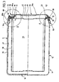
- the food transport container has a cuboid container body 10 with a first and a second side wall 12 and 14, respectively Rear wall 16, an upper wall 18 and a bottom wall 20; on his right front end according to Figures 2 and 3 22, the container body 10 is open, i. H. with an approx rectangular loading and unloading opening 24, which itself can be closed with a door 26.
- the latter has roughly the shape of a rectangular plate, which when closed Door the front end 22 of the container body 10 substantially covered, by means of an upper and a lower Hinge device 28 or 30 about a vertical axis 32 is pivotally attached to the container body 10 and in it in the closed position shown in Figures 1 to 3 by means of a closure device 34 locked on the container body 10 can be.
- the container body 10 is an outer shell 36 and one Inner shell 38 formed, designed and with each other are connected that one between the two shells Cavity 40 results, which does not with one in the drawing insulation material shown filled, for. B. with a plastic foam is foamed.
- a plastic foam is foamed.
- the outer shell 36 is advantageously a molded plastic part.
- the outer wall 44 is also preferred around a plastic molding.
- the hinge device should now be used with reference to FIGS 28 are explained in more detail - the lower hinge device 30 is designed exactly like the upper hinge device 28 and in the same way on the container body 10 and the Door 26 attached.
- the hinge device 28 consists of two units, namely a first unit 50 attached to the side wall 12 and a second unit 52 attached to the door 26, which so articulated with each other in a manner yet to be described are connected that they are relative to each other about the pivot axis 32 can be pivoted.
- the first unit has 50 a support member 54 attached to the side wall 12, the shape of which roughly corresponds to that of a rectangular plate, on the right edge according to FIG. 4, a bottom closed Sleeve 56 is integrally formed; acts advantageously it is in one piece in the support member 54 and the sleeve 56 Plastic injection molding.
- In the sleeve 56 is from a hinge pin 58 pressed in, which the Defined pivot axis 32.
- the second unit 52 has a supporting part fastened to the door 26 60, whose shape is also roughly that of one rectangular plate corresponds to the left of FIG. 4
- a support part 62 and a hinge element 64 are integrally formed are.
- the support member 62 has approximately the shape of a solid Circular cylinder while the shape of the hinge element 64 corresponds to a wall segment of a hollow circular cylinder.
- the second unit 52 should also be an injection molded plastic part act. As best seen in FIG.
- the hinge element 64 includes the hinge pin 58 over more than 180 °, but significantly less than 360 ° so that a cutout 64a remains which is so large that the door 26 with elastic expansion of the hinge elements 64 of the two hinge devices 28 and 30 in the horizontal direction from the hinge pin 58 of the two Hinge devices and thus from the container body 10 can be released - the door 26 is as in FIGS. 5 and 6 shown or swung open a little further and bumps a person passing by, one at the food transport container passing car or the like against the swung open Door, this is drawn in the direction of Fig. 5 Arrow "F" blasted off the container body 10 without that thereby the door, one of the hinge devices or the Container body is damaged.
- the Door 26 with the hinge elements 64 of the two hinge devices 28, 30 simply from above onto the two hinge bolts 58 slide on and in the opposite direction from the container body 10 solve.
- the door attached to the container body 10 26 the latter is supported with a support region 62a of the Support part 62 on top of the hinge pin 58 and / or with the hinge element 64 on one formed by the sleeve 56 Edition 56a from.
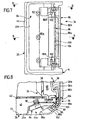
- the closure device 34 consists of three parts, namely an approximately plate-shaped attached to the door 26 Support part 84, a tension lever 86 and one of these two parts articulated joint element 88.
- the hinge element 88 has approximately the shape a staple with two U-shaped end portions and a straight rod area connecting these to each other 88a; the two U-shaped end regions each form one Axle stub 88b, the two stub axles together are coaxial and run parallel to the rod area 88a.
- the hinge element 88 defines two to each other parallel pivot axes, namely one through the rod area 88a defines first pivot axis 100 and one defined by second axis stub 88b defined second pivot axis 102.
- this has a groove 104 on its back, into which the Rod area 88a of the joint element is inserted - the outer wall 44 of door 26 prevents rod area 88a from leaving the groove 104.
- the clamping lever 86 is designed as a double-armed lever, the one rigid arm a handle 86a and the other, elastic flexible arm forms a clamping claw 86b. Moreover is the clamping lever 86 in the one shown in Figures 8 to 11 Way angled in such a way that when closed Door 26 the front edge of the second side wall 14 of the Container body 10 overlaps (see Figures 8 and 9).
- the handle 86a does not project forward over the door 26 is its outer wall 44 provided with a recess 44a, which when closed and locked door receives the handle 86a (see figures 8 and 9).
- the outer shell 36 is in the region of the second Sidewall 14 with an undercut 36a Provide recess 36b, in which the clamping claw 86b engage and can reach behind the undercut 36a (see Figures 8 and 9).
- the construction is designed so that with the door locked (i.e. in the one shown in the figures 8 and 9 shown state) of the clamping lever 86 as a Toggle lever acts and due to the elastic training of the then slightly pre-tensioned claw 86b against the door 26 the front end faces of the side walls 12, 14, the upper Wall 18 and the bottom wall 20 of the container body 10 presses.
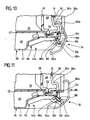
- the procedure for unlocking and opening the door 26 is as follows: Thanks to the design of the recess according to the invention 44a, the handle 86a of the tensioning lever 86 can be operated with or reach behind several fingers and then in accordance with FIG Swivel counterclockwise so that the clamping lever 86 is occupies the position shown in Fig. 10; around the claw 86b to be removed from the undercut 36a and out of the recess 36b lead out, then the tensioning lever 86 is still pivoted a little further counterclockwise and parallel shifted to itself, like this a comparison of the figures 10 and 11 shows what the door swung open can be.
- Fig. 11 shows particularly clearly that thanks the inventive design and arrangement of the closure device 34 then unlock and swing open the door can, if there is a second in addition to the food transport container such container is located, with a very small lateral Sufficient distance between the two containers is.
Landscapes
- Engineering & Computer Science (AREA)
- Mechanical Engineering (AREA)
- Closures For Containers (AREA)
- Packages (AREA)
Description
- Fig. 1
- eine Frontansicht des Speisentransportbehälters bei verschlossener Tür;
- Fig. 2
- eine Seitenansicht des Speisentransportbehälters gemäß Fig. 1 von links gesehen;
- Fig. 3
- einen Schnitt durch den Speisentransportbehälter entsprechend der Linie 3-3 in Fig. 1;
- Fig. 4
- eine Ansicht der einen Scharniervorrichtung mit an diese angrenzenden Teilen des Behälterkorpus und der Tür, welche um ungefähr 45° aufgeschwenkt ist;
- Fig. 5
- einen Schnitt nach der Linie 5-5 in Fig. 4, welcher dem in Fig. 3 mit "A" gekennzeichneten Ausschnitt entspricht, jedoch nach Aufschwenken der Tür um ca. 45°;
- Fig. 6
- einen Schnitt nach der Linie 6-6 in Fig. 4;
- Fig. 7
- eine Frontansicht des mit der Verschlußvorrichtung versehenen Bereichs der Tür;
- Fig. 8
- einen Schnitt nach der Linie 8-8 in Fig. 7, jedoch auch durch einen an die Tür angrenzenden Bereich der zweiten Seitenwand des Behälterkorpus, so daß die Fig. 8 dem in Fig. 3 mit "B" gekennzeichneten Bereich entspricht;
- Fig. 9
- einen Schnitt nach der Linie 9-9 in Fig. 7;
- Fig. 10
- eine der Fig. 9 entsprechende Darstellung, jedoch nachdem der Spannhebel eine erste Phase seiner öffnungsbewegung durchlaufen hat, und
- Fig. 11
- die in Fig. 10 gezeigten Teile, jedoch nachdem der Spannhebel so weiterbewegt wurde, daß sich die Tür aufschwenken läßt.
Claims (19)
- Ungefähr quaderförmiger Speisentransportbehälter mit wärmeisolierenden Eigenschaften, welcher einen gleichfalls ungefähr quaderförmigen, einen Behälterinnenraum bildenden Behälterkorpus mit zwei Seitenwänden, einer Rückwand, einer Bodenwand und einer oberen Wand sowie eine ungefähr rechteckige Tür zum Verschließen einer von den vorderen Stirnseiten der Seitenwände, der Bodenwand und der oberen Wand definierten Be- und Entladeöffnung des Behälterkorpus aufweist, wobei die Tür die vordere Stirnseite des Behälterkorpus im wesentlichen überdeckt, im Bereich der einen, ersten Seitenwand des Behälterkorpus an diesem mittels mindestens einer Scharniervorrichtung um eine vertikale Scharnierachse schwenkbar angelenkt sowie im Bereich der anderen, zweiten Seitenwand des Behälterkorpus mittels mindestens einer Verschlußvorrichtung in ihrer Schließstellung am Behälterkorpus festlegbar ist, dadurch gekennzeichnet, daß die Scharniervorrichtung eine am Behälterkorpus angebrachte erste Einheit mit einem am Behälterkorpus befestigten ersten Tragteil und einem vertikal verlaufenden, sich vom ersten Tragteil nach oben wegerstreckenden Scharnierbolzen mit freiem oberem Ende sowie eine an der Tür angebrachte zweite Einheit mit einem auf den Scharnierbolzen von oben aufschiebbaren und an diesem drehbar gelagerten Scharnierelement aufweist, wobei das Scharnierelement den Scharnierbolzen über mehr als 180°, jedoch über so viel weniger als 360° umfaßt und derart elastisch aufweitbar ist, daß die Tür in einer quer zur Scharnierachse verlaufenden Richtung zerstörungsfrei vom Scharnierbolzen und damit vom Behälterkorpus absprengbar ist.
- Speisentransportbehälter nach Anspruch 1, dadurch gekennzeichnet, daß die erste Einheit der Scharniervorrichtung am Scharnierbolzen oder mit dem Übergang vom Scharnierbolzen zum ersten Tragteil eine Auflage für das Scharnierelement der zweiten Einheit der Scharniervorrichtung aufweist bzw. bildet.
- Speisentransportbehälter nach Anspruch 1 oder 2, dadurch gekennzeichnet, daß zwei in vertikalem Abstand voneinander angeordnete Scharniervorrichtungen vorgesehen sind.
- Speisentransportbehälter nach einem oder mehreren der Ansprüche 1 bis 3, dadurch gekennzeichnet, daß die Scharnierachse mindestens ungefähr mit der Schnittlinie der von der vorderen Stirnseite des Behälterkorpus und der von der Außenseite der ersten Seitenwand des Behälterkorpus definierten Ebenen zusammenfällt.
- Speisentransportbehälter nach einem oder mehreren der Ansprüche 1 bis 4, dadurch gekennzeichnet, daß das erste Tragteil ungefähr plattenförmig ist und im Bereich seines einen, ungefähr vertikal verlaufenden Randes den Scharnierbolzen trägt.
- Speisentransportbehälter nach Anspruch 5, dadurch gekennzeichnet, daß das erste Tragteil ein Kunststoff-Spritzgußteil mit einer angeformten, unten geschlossenen Hülse ist, wobei der Scharnierbolzen von oben in die Hülse eingesetzt und in dieser festgelegt ist.
- Speisentransportbehälter nach einem oder mehreren der Ansprüche 1 bis 6, dadurch gekennzeichnet, daß die zweite Einheit ein ungefähr plattenförmiges zweites Tragteil aufweist, welches im Bereich seines einen, ungefähr vertikal verlaufenden Randes das Scharnierelement trägt.
- Speisentransportbehälter nach Anspruch 7, dadurch gekennzeichnet, daß die zweite Einheit ein Kunststoff-Spritzgußteil ist.
- Speisentransportbehälter nach einem oder mehreren der Ansprüche 1 bis 8, dadurch gekennzeichnet, daß die zweite Einheit einen auf dem freien oberen Ende des Scharnierbolzens aufliegenden Abstützbereich aufweist.
- Speisentransportbehälter nach einem oder mehreren der Ansprüche 1 bis 9, dadurch gekennzeichnet, daß die Tür an ihrem der Scharniervorrichtung benachbarten Rand mit einer der Vergrößerung des Aufschwenkwinkels der Tür dienenden Abschrägung versehen ist.
- Speisentransportbehälter nach den Ansprüchen 7 und 10, dadurch gekennzeichnet, daß das zweite Tragteil auf der Abschrägung befestigt ist.
- Speisentransportbehälter nach einem oder mehreren der Ansprüche 1 bis 11, dadurch gekennzeichnet, daß das erste Tragteil einen elastischen, pufferartigen Bereich zum Abfedern der aufschwenkenden Tür aufweist.
- Speisentransportbehälter nach einem oder mehreren der Ansprüche 1 bis 12, dadurch gekennzeichnet, daß die Verschlußvorrichtung ein an der Tür angebrachtes Tragteil, einen doppelarmigen Spannhebel sowie mindestens ein den letzteren tragendes und insbesondere einteiliges Gelenkelement aufweist, welches am Tragteil um eine erste vertikale Achse und am Spannhebel um eine zweite vertikale Achse schwenkbar angebracht ist, daß ein sich an der Frontseite der Tür befindlicher erster Arm des Spannhebels einen Griff bildet und ein zweiter Arm des Spannhebels im Bereich seines freien Endes krallenartig ausgebildet ist, und daß der Behälterkorpus an seiner zweiten Seitenwand eine durch das krallenartige Spannhebelende hintergreifbare Hinterschneidung aufweist und der Spannhebel derart abgewinkelt ist, daß er bei verschlossener Tür den vorderen Rand der zweiten Seitenwand des Behälterkorpus übergreift.
- Speisentransportbehälter nach Anspruch 13, dadurch gekennzeichnet, daß der zweite Spannhebelarm bezüglich des ersten Spannhebelarms in Richtung quer zu den beiden Schwenkachsen elastisch auslenkbar ist.
- Speisentransportbehälter nach Anspruch 13 oder 14, dadurch gekennzeichnet, daß bei verschlossener Tür der erste Spannhebelarm nicht über die Frontseite der Tür übersteht.
- Speisentransportbehälter nach Anspruch 15, dadurch gekennzeichnet, daß die Tür eine Vertiefung zur Aufnahme des ersten Spannhebelarms aufweist.
- Speisentransportbehälter nach einem oder mehreren der Ansprüche 13 bis 16, dadurch gekennzeichnet, daß die beiden vom Gelenkelement definierten Schwenkachsen derart angeordnet sind, daß, ausgehend von einem Zustand, in dem die Tür verschlossen ist, zunächst der erste Spannhebelarm verschwenkbar ist, ohne daß das krallenartige Spannhebelende die Hinterschneidung verläßt, worauf der Spannhebel zum Lösen seines krallenartigen Endes von der Hinterschneidung derart weiter bewegbar ist, daß er sowohl eine Schwenkbewegung durchführt als auch parallel zu sich selbst verlagert wird.
- Speisentransportbehälter nach einem oder mehreren der Ansprüche 13 bis 17, dadurch gekennzeichnet, daß der Behälter nur eine einzige Verschlußvorrichtung aufweist, welche ungefähr mittig an der Tür angeordnet ist.
- Speisentransportbehälter nach einem oder mehreren der Ansprüche 1 bis 18, dadurch gekennzeichnet, daß in eine Außenwandung des Behälterkorpus sowie eine Außenwandung der Tür Muttern lagefixiert eingelegt sind, so daß die Einheiten der Scharniervorrichtung und das Tragteil der Verschlußvorrichtung mittels Schrauben montierbar sind.
Applications Claiming Priority (2)
| Application Number | Priority Date | Filing Date | Title |
|---|---|---|---|
| DE29803503U DE29803503U1 (de) | 1998-02-28 | 1998-02-28 | Speisentransportbehälter |
| DE29803503U | 1998-02-28 |
Publications (2)
| Publication Number | Publication Date |
|---|---|
| EP0939187A1 EP0939187A1 (de) | 1999-09-01 |
| EP0939187B1 true EP0939187B1 (de) | 2003-03-19 |
Family
ID=8053342
Family Applications (1)
| Application Number | Title | Priority Date | Filing Date |
|---|---|---|---|
| EP98124259A Expired - Lifetime EP0939187B1 (de) | 1998-02-28 | 1998-12-18 | Speisentransportbehälter |
Country Status (2)
| Country | Link |
|---|---|
| EP (1) | EP0939187B1 (de) |
| DE (2) | DE29803503U1 (de) |
Cited By (3)
| Publication number | Priority date | Publication date | Assignee | Title |
|---|---|---|---|---|
| WO2023073010A1 (en) * | 2021-10-29 | 2023-05-04 | Dometic Sweden Ab | Backpack and system for food delivery |
| USD1033157S1 (en) | 2020-12-09 | 2024-07-02 | Dometic Sweden Ab | Delivery box |
| USD1035391S1 (en) | 2021-11-05 | 2024-07-16 | Dometic Sweden Ab | Delivery box |
Families Citing this family (1)
| Publication number | Priority date | Publication date | Assignee | Title |
|---|---|---|---|---|
| DE102004025389B4 (de) * | 2004-05-17 | 2006-05-04 | Blanco Gmbh + Co Kg | Scharnier zum schwenkbaren Haltern einer Tür |
Family Cites Families (3)
| Publication number | Priority date | Publication date | Assignee | Title |
|---|---|---|---|---|
| FR2295205A1 (fr) * | 1974-07-24 | 1976-07-16 | Pommier & Cie | Charniere de ridelle decrochable |
| US4171151A (en) * | 1978-03-27 | 1979-10-16 | Luck Thomas J | Food carrier |
| IT1267401B1 (it) * | 1994-02-22 | 1997-02-05 | Monetti Spa | Contenitore isotermico di pasti caldi, particolarmente per ristorazione collettiva. |
-
1998
- 1998-02-28 DE DE29803503U patent/DE29803503U1/de not_active Expired - Lifetime
- 1998-12-18 DE DE59807555T patent/DE59807555D1/de not_active Expired - Lifetime
- 1998-12-18 EP EP98124259A patent/EP0939187B1/de not_active Expired - Lifetime
Cited By (3)
| Publication number | Priority date | Publication date | Assignee | Title |
|---|---|---|---|---|
| USD1033157S1 (en) | 2020-12-09 | 2024-07-02 | Dometic Sweden Ab | Delivery box |
| WO2023073010A1 (en) * | 2021-10-29 | 2023-05-04 | Dometic Sweden Ab | Backpack and system for food delivery |
| USD1035391S1 (en) | 2021-11-05 | 2024-07-16 | Dometic Sweden Ab | Delivery box |
Also Published As
| Publication number | Publication date |
|---|---|
| DE59807555D1 (de) | 2003-04-24 |
| DE29803503U1 (de) | 1998-05-14 |
| EP0939187A1 (de) | 1999-09-01 |
Similar Documents
| Publication | Publication Date | Title |
|---|---|---|
| DE60024543T2 (de) | Vorrichtung zum automatisch durch Schwerkraft Verriegeln und Entriegeln des Deckels eines Behälters sowie Behälter mit einer derartigen Vorrichtung | |
| DE19910564C2 (de) | Sicherheitsverriegelung, insbesondere für Türen in Einbauten von Wohnmobilen | |
| DE68904574T2 (de) | Kaestchen mit einem behaelterglied und einem angelenkten deckelglied, und mit einer verschlussvorrichtung, bestehend aus mindestens einem beweglichen element, das mit festen elementen des deckel- und behaeltergliedes mitwirkt. | |
| DE2919079C2 (de) | Bügelförmiger Schließkloben für einen Kfz-Kofferraumdeckel | |
| DE4127934A1 (de) | Behaelter | |
| EP0958177B1 (de) | Behälter insbesondere für den transport von obst und gemüse | |
| DE4009960A1 (de) | Mehrteiliger, insbesondere zweiteiliger flaschenkasten aus kunststoff | |
| DE3829485C2 (de) | ||
| DE9014577U1 (de) | Verschlußeinrichtung für Koffer, Taschen o.dgl. | |
| EP2850011B1 (de) | Verriegelung für klappe | |
| EP0939187A1 (de) | Speisentransportbehälter | |
| EP0455935B1 (de) | Abschliessbarer Müllbehälter | |
| EP1900892B1 (de) | Drehstangenverschluss | |
| EP1354824B1 (de) | Bausatz für einen Müllbehälter mit Steckgriffen | |
| EP1889991B1 (de) | Drehstangenverschluss für eine Türverriegelung | |
| DE3809317A1 (de) | Tuerschloss | |
| EP3521738A1 (de) | Kühlgutträger und kältegerätetür | |
| DE29815650U1 (de) | Seitliche Einfassung für Bordwände von Nutzfahrzeugen mit integriertem Riegelverschluß | |
| DE9005487U1 (de) | Schrankwagen | |
| EP0414164B1 (de) | Verschluss für Koffer oder dergleichen | |
| DE102010002542B4 (de) | Transportwagen mit Verschlussvorrichtung und Verriegelungsvorrichtung | |
| DE102004021172B4 (de) | Verschwenkbare Deckeleinheit für großvolumige Umleerbehälter | |
| CH602067A5 (en) | Post delivery box for home or office use | |
| DE9210784U1 (de) | Verschlußvorrichtung für Türen, Klappen, Bordwände von insbesondere Nutzfahrzeugaufbauten | |
| DE102005011745A1 (de) | Briefkasten |
Legal Events
| Date | Code | Title | Description |
|---|---|---|---|
| PUAI | Public reference made under article 153(3) epc to a published international application that has entered the european phase |
Free format text: ORIGINAL CODE: 0009012 |
|
| AK | Designated contracting states |
Kind code of ref document: A1 Designated state(s): BE DE FR GB IT NL |
|
| AX | Request for extension of the european patent |
Free format text: AL;LT;LV;MK;RO;SI |
|
| 17P | Request for examination filed |
Effective date: 19990820 |
|
| AKX | Designation fees paid |
Free format text: BE DE FR GB IT NL |
|
| GRAH | Despatch of communication of intention to grant a patent |
Free format text: ORIGINAL CODE: EPIDOS IGRA |
|
| GRAH | Despatch of communication of intention to grant a patent |
Free format text: ORIGINAL CODE: EPIDOS IGRA |
|
| RAP1 | Party data changed (applicant data changed or rights of an application transferred) |
Owner name: BLANCO GMBH + CO KG |
|
| GRAA | (expected) grant |
Free format text: ORIGINAL CODE: 0009210 |
|
| AK | Designated contracting states |
Designated state(s): BE DE FR GB IT NL |
|
| REG | Reference to a national code |
Ref country code: GB Ref legal event code: FG4D Free format text: NOT ENGLISH |
|
| REF | Corresponds to: |
Ref document number: 59807555 Country of ref document: DE Date of ref document: 20030424 Kind code of ref document: P |
|
| GBT | Gb: translation of ep patent filed (gb section 77(6)(a)/1977) | ||
| ET | Fr: translation filed | ||
| PLBE | No opposition filed within time limit |
Free format text: ORIGINAL CODE: 0009261 |
|
| STAA | Information on the status of an ep patent application or granted ep patent |
Free format text: STATUS: NO OPPOSITION FILED WITHIN TIME LIMIT |
|
| 26N | No opposition filed |
Effective date: 20031222 |
|
| REG | Reference to a national code |
Ref country code: GB Ref legal event code: 732E |
|
| PGFP | Annual fee paid to national office [announced via postgrant information from national office to epo] |
Ref country code: IT Payment date: 20101224 Year of fee payment: 13 Ref country code: GB Payment date: 20101215 Year of fee payment: 13 |
|
| PGFP | Annual fee paid to national office [announced via postgrant information from national office to epo] |
Ref country code: FR Payment date: 20111219 Year of fee payment: 14 Ref country code: NL Payment date: 20111220 Year of fee payment: 14 |
|
| PGFP | Annual fee paid to national office [announced via postgrant information from national office to epo] |
Ref country code: BE Payment date: 20111229 Year of fee payment: 14 |
|
| PGFP | Annual fee paid to national office [announced via postgrant information from national office to epo] |
Ref country code: DE Payment date: 20120126 Year of fee payment: 14 |
|
| BERE | Be: lapsed |
Owner name: *BLANCO G.M.B.H. + CO. K.G. Effective date: 20121231 |
|
| REG | Reference to a national code |
Ref country code: NL Ref legal event code: V1 Effective date: 20130701 |
|
| GBPC | Gb: european patent ceased through non-payment of renewal fee |
Effective date: 20121218 |
|
| REG | Reference to a national code |
Ref country code: FR Ref legal event code: ST Effective date: 20130830 |
|
| PG25 | Lapsed in a contracting state [announced via postgrant information from national office to epo] |
Ref country code: BE Free format text: LAPSE BECAUSE OF NON-PAYMENT OF DUE FEES Effective date: 20121231 |
|
| PG25 | Lapsed in a contracting state [announced via postgrant information from national office to epo] |
Ref country code: NL Free format text: LAPSE BECAUSE OF NON-PAYMENT OF DUE FEES Effective date: 20130701 Ref country code: DE Free format text: LAPSE BECAUSE OF NON-PAYMENT OF DUE FEES Effective date: 20130702 |
|
| REG | Reference to a national code |
Ref country code: DE Ref legal event code: R119 Ref document number: 59807555 Country of ref document: DE Effective date: 20130702 |
|
| PG25 | Lapsed in a contracting state [announced via postgrant information from national office to epo] |
Ref country code: FR Free format text: LAPSE BECAUSE OF NON-PAYMENT OF DUE FEES Effective date: 20130102 Ref country code: GB Free format text: LAPSE BECAUSE OF NON-PAYMENT OF DUE FEES Effective date: 20121218 |
|
| PG25 | Lapsed in a contracting state [announced via postgrant information from national office to epo] |
Ref country code: IT Free format text: LAPSE BECAUSE OF NON-PAYMENT OF DUE FEES Effective date: 20121218 |