EP0938976A1 - Ansteuerungsverfahren für einen Aufzeichnungskopf - Google Patents
Ansteuerungsverfahren für einen Aufzeichnungskopf Download PDFInfo
- Publication number
- EP0938976A1 EP0938976A1 EP99103374A EP99103374A EP0938976A1 EP 0938976 A1 EP0938976 A1 EP 0938976A1 EP 99103374 A EP99103374 A EP 99103374A EP 99103374 A EP99103374 A EP 99103374A EP 0938976 A1 EP0938976 A1 EP 0938976A1
- Authority
- EP
- European Patent Office
- Prior art keywords
- ink
- scanning direction
- nozzles
- heads
- head
- Prior art date
- Legal status (The legal status is an assumption and is not a legal conclusion. Google has not performed a legal analysis and makes no representation as to the accuracy of the status listed.)
- Granted
Links
Images


Classifications
-
- B—PERFORMING OPERATIONS; TRANSPORTING
- B41—PRINTING; LINING MACHINES; TYPEWRITERS; STAMPS
- B41J—TYPEWRITERS; SELECTIVE PRINTING MECHANISMS, i.e. MECHANISMS PRINTING OTHERWISE THAN FROM A FORME; CORRECTION OF TYPOGRAPHICAL ERRORS
- B41J2/00—Typewriters or selective printing mechanisms characterised by the printing or marking process for which they are designed
- B41J2/005—Typewriters or selective printing mechanisms characterised by the printing or marking process for which they are designed characterised by bringing liquid or particles selectively into contact with a printing material
- B41J2/01—Ink jet
- B41J2/07—Ink jet characterised by jet control
-
- B—PERFORMING OPERATIONS; TRANSPORTING
- B41—PRINTING; LINING MACHINES; TYPEWRITERS; STAMPS
- B41J—TYPEWRITERS; SELECTIVE PRINTING MECHANISMS, i.e. MECHANISMS PRINTING OTHERWISE THAN FROM A FORME; CORRECTION OF TYPOGRAPHICAL ERRORS
- B41J2/00—Typewriters or selective printing mechanisms characterised by the printing or marking process for which they are designed
- B41J2/005—Typewriters or selective printing mechanisms characterised by the printing or marking process for which they are designed characterised by bringing liquid or particles selectively into contact with a printing material
- B41J2/01—Ink jet
- B41J2/015—Ink jet characterised by the jet generation process
- B41J2/04—Ink jet characterised by the jet generation process generating single droplets or particles on demand
- B41J2/045—Ink jet characterised by the jet generation process generating single droplets or particles on demand by pressure, e.g. electromechanical transducers
- B41J2/04501—Control methods or devices therefor, e.g. driver circuits, control circuits
- B41J2/04505—Control methods or devices therefor, e.g. driver circuits, control circuits aiming at correcting alignment
-
- B—PERFORMING OPERATIONS; TRANSPORTING
- B41—PRINTING; LINING MACHINES; TYPEWRITERS; STAMPS
- B41J—TYPEWRITERS; SELECTIVE PRINTING MECHANISMS, i.e. MECHANISMS PRINTING OTHERWISE THAN FROM A FORME; CORRECTION OF TYPOGRAPHICAL ERRORS
- B41J2/00—Typewriters or selective printing mechanisms characterised by the printing or marking process for which they are designed
- B41J2/005—Typewriters or selective printing mechanisms characterised by the printing or marking process for which they are designed characterised by bringing liquid or particles selectively into contact with a printing material
- B41J2/01—Ink jet
- B41J2/015—Ink jet characterised by the jet generation process
- B41J2/04—Ink jet characterised by the jet generation process generating single droplets or particles on demand
- B41J2/045—Ink jet characterised by the jet generation process generating single droplets or particles on demand by pressure, e.g. electromechanical transducers
- B41J2/04501—Control methods or devices therefor, e.g. driver circuits, control circuits
- B41J2/04541—Specific driving circuit
-
- B—PERFORMING OPERATIONS; TRANSPORTING
- B41—PRINTING; LINING MACHINES; TYPEWRITERS; STAMPS
- B41J—TYPEWRITERS; SELECTIVE PRINTING MECHANISMS, i.e. MECHANISMS PRINTING OTHERWISE THAN FROM A FORME; CORRECTION OF TYPOGRAPHICAL ERRORS
- B41J2/00—Typewriters or selective printing mechanisms characterised by the printing or marking process for which they are designed
- B41J2/005—Typewriters or selective printing mechanisms characterised by the printing or marking process for which they are designed characterised by bringing liquid or particles selectively into contact with a printing material
- B41J2/01—Ink jet
- B41J2/015—Ink jet characterised by the jet generation process
- B41J2/04—Ink jet characterised by the jet generation process generating single droplets or particles on demand
- B41J2/045—Ink jet characterised by the jet generation process generating single droplets or particles on demand by pressure, e.g. electromechanical transducers
- B41J2/04501—Control methods or devices therefor, e.g. driver circuits, control circuits
- B41J2/04543—Block driving
-
- B—PERFORMING OPERATIONS; TRANSPORTING
- B41—PRINTING; LINING MACHINES; TYPEWRITERS; STAMPS
- B41J—TYPEWRITERS; SELECTIVE PRINTING MECHANISMS, i.e. MECHANISMS PRINTING OTHERWISE THAN FROM A FORME; CORRECTION OF TYPOGRAPHICAL ERRORS
- B41J2/00—Typewriters or selective printing mechanisms characterised by the printing or marking process for which they are designed
- B41J2/005—Typewriters or selective printing mechanisms characterised by the printing or marking process for which they are designed characterised by bringing liquid or particles selectively into contact with a printing material
- B41J2/01—Ink jet
- B41J2/015—Ink jet characterised by the jet generation process
- B41J2/04—Ink jet characterised by the jet generation process generating single droplets or particles on demand
- B41J2/045—Ink jet characterised by the jet generation process generating single droplets or particles on demand by pressure, e.g. electromechanical transducers
- B41J2/04501—Control methods or devices therefor, e.g. driver circuits, control circuits
- B41J2/0458—Control methods or devices therefor, e.g. driver circuits, control circuits controlling heads based on heating elements forming bubbles
-
- B—PERFORMING OPERATIONS; TRANSPORTING
- B41—PRINTING; LINING MACHINES; TYPEWRITERS; STAMPS
- B41J—TYPEWRITERS; SELECTIVE PRINTING MECHANISMS, i.e. MECHANISMS PRINTING OTHERWISE THAN FROM A FORME; CORRECTION OF TYPOGRAPHICAL ERRORS
- B41J2/00—Typewriters or selective printing mechanisms characterised by the printing or marking process for which they are designed
- B41J2/005—Typewriters or selective printing mechanisms characterised by the printing or marking process for which they are designed characterised by bringing liquid or particles selectively into contact with a printing material
- B41J2/01—Ink jet
- B41J2/015—Ink jet characterised by the jet generation process
- B41J2/04—Ink jet characterised by the jet generation process generating single droplets or particles on demand
- B41J2/045—Ink jet characterised by the jet generation process generating single droplets or particles on demand by pressure, e.g. electromechanical transducers
- B41J2/04501—Control methods or devices therefor, e.g. driver circuits, control circuits
- B41J2/04581—Control methods or devices therefor, e.g. driver circuits, control circuits controlling heads based on piezoelectric elements
-
- B—PERFORMING OPERATIONS; TRANSPORTING
- B41—PRINTING; LINING MACHINES; TYPEWRITERS; STAMPS
- B41J—TYPEWRITERS; SELECTIVE PRINTING MECHANISMS, i.e. MECHANISMS PRINTING OTHERWISE THAN FROM A FORME; CORRECTION OF TYPOGRAPHICAL ERRORS
- B41J2/00—Typewriters or selective printing mechanisms characterised by the printing or marking process for which they are designed
- B41J2/005—Typewriters or selective printing mechanisms characterised by the printing or marking process for which they are designed characterised by bringing liquid or particles selectively into contact with a printing material
- B41J2/01—Ink jet
- B41J2/135—Nozzles
- B41J2/145—Arrangement thereof
- B41J2/155—Arrangement thereof for line printing
-
- B—PERFORMING OPERATIONS; TRANSPORTING
- B41—PRINTING; LINING MACHINES; TYPEWRITERS; STAMPS
- B41J—TYPEWRITERS; SELECTIVE PRINTING MECHANISMS, i.e. MECHANISMS PRINTING OTHERWISE THAN FROM A FORME; CORRECTION OF TYPOGRAPHICAL ERRORS
- B41J2/00—Typewriters or selective printing mechanisms characterised by the printing or marking process for which they are designed
- B41J2/005—Typewriters or selective printing mechanisms characterised by the printing or marking process for which they are designed characterised by bringing liquid or particles selectively into contact with a printing material
- B41J2/01—Ink jet
- B41J2/21—Ink jet for multi-colour printing
- B41J2/2132—Print quality control characterised by dot disposition, e.g. for reducing white stripes or banding
-
- B—PERFORMING OPERATIONS; TRANSPORTING
- B41—PRINTING; LINING MACHINES; TYPEWRITERS; STAMPS
- B41J—TYPEWRITERS; SELECTIVE PRINTING MECHANISMS, i.e. MECHANISMS PRINTING OTHERWISE THAN FROM A FORME; CORRECTION OF TYPOGRAPHICAL ERRORS
- B41J2202/00—Embodiments of or processes related to ink-jet or thermal heads
- B41J2202/01—Embodiments of or processes related to ink-jet heads
- B41J2202/10—Finger type piezoelectric elements
Definitions
- the present invention relates to a method for driving a recording head that is composed of a plurality of ink-jet heads.
- An example of a printer that uses a recording head composed of a plurality of ink-jet heads is an ink-jet color printer, which is equipped with ink-jet heads each for a respective one of four colors of ink (yellow, cyan, magenta, and black) and drives these heads to provide full-color printing.
- Such a recording head achieves color printing by superimposing each of colored dots of yellow, cyan, magenta, and black on top of the other and therefore has a requirement for strict control of the distance between each head ink nozzle.
- a method which solves the misalignment of printed dots by displacing the printing timing according to the pitch corresponding to a mounting error between each ink jet head.
- the misalignment of printed dots in the sub-scanning direction in which a printing medium travels can be corrected by providing a plurality of clocks that permit the printing initiation timing to be selected for each ink jet head and selecting the printing initiation timing according to the displacements of the printing pitch.
- the provision of a clock four times the normal printing period allows for electrical correction of up to 1/4 pitch of displacement in the sub-scanning direction.
- a method which corrects printing positions by providing a delay circuit for a position displacement for each printing line and displacing the printing timing through the delay circuit. Furthermore, as described in Japanese Unexamined Patent Publication No. 7-156452, a method is also known which utilizes a buffer memory to ensure delay control and high picture quality control.
- the technique that uses a plurality of clocks that allow the printing initiation timing to be selected for each ink jet head requires the clock speed to be increased, which results in complication of control and an increase in cost.
- the delay circuit-based technique has a problem that control becomes complicated.
- the techniques disclosed in the patent publication needs a basic clock of N times the highest response frequency for printing and a buffer memory, which complicates control as a result of the increased driving frequency.
- a method of driving a recording head in which a plurality of ink jet heads each having a large number of ink chambers each provided with an ink nozzle are arranged in parallel with each other in a main scanning direction perpendicular to a direction in which a recording medium moves relative to the heads and are spaced apart from each other by a predetermined distance in a sub-scanning direction in which the recording medium moves, comprising dividing the ink chambers of each of the ink jet heads into N (an integer of two or more) sets each including every N-th ink chamber, placing ink nozzles of N ink chambers each included in a respective one of the N sets in a staggered arrangement, driving the ink chambers on a time division basis for each set, and, when the amount of misalignment between dots recorded by droplets of ink ejected from ink nozzles of a set of ink chambers in a reference head of the heads and dots recorded by droplets of ink ejected
- This method allows alignment error between printed dots in the sub-scanning direction to be corrected through simple control.
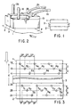
- ink jet heads 1 and 2 are fixed with adhesive to both sides of a substrate 3 which are parallel to each other to thereby form one recording head assembly.
- the ink jet heads 1 and 2 and the substrate 3 are of such configuration as show in FIG. 2.
- the ink jet heads 1 and 2 each with a large number of ink chambers are fixed to the respective sides of the substrate 3.
- Ink supply tubes 1a and 2a are connected to the ink jet heads 1 and 2, respectively.
- ink jet heads 1 and 2 To portions of the ink jet heads 1 and 2 are respectively mounted connectors 1b and 2b with which cables 1c and 2c are connected respectively. Through these cables the ink jet heads 1 and 2 are supplied with drive voltages.
- P denotes a sheet of paper as a recording medium.
- the ink jet heads 1 and 2 are formed with ink nozzles 41 to 49, ⁇ and 51 to 59, ⁇ each corresponding to a respective one of the ink chambers. These ink nozzles are placed in a staggered arrangement for every three nozzles. That is, these ink nozzles 41 to 49, ⁇ of the ink jet head 1 are arranged at regular intervals of pitch 2P in the main scanning direction perpendicular to the direction of movement of the recording medium indicated by an arrow.
- the ink chambers are divided into three sets each including every third head. That is, the ink nozzles 41, 44, 47, etc. form a first set.
- the nozzles 42, 45, 48, etc. form a second set, and the nozzles 43, 46, 49, etc. form a third set.
- the ink nozzles 41, 44, 47, etc. in the first set to which reference is made are arranged on a line 1a.
- the ink nozzles 42, 45, 48, etc. in the second set are arranged on a line 1b which is offset from the line 1a by given pitch D in the sub-scanning direction in which the recording medium travels.
- the ink nozzles 43, 46, 49, etc. in the third set are arranged on a line 1c which is offset from the line 1b by the pitch D in the sub-scanning direction.
- the ink chambers are divided into three sets each including every third head. That is, the ink nozzles 51, 54, 57, etc. form a first set. The nozzles 52, 55, 58, etc. form a second set, and the nozzles 53, 56, 59, etc. form a third set.
- the ink nozzles 51, 54, 57, etc. in the first set are arranged on a line 2a which is spaced apart from the reference line 1a by distance d in the sub-scanning direction.
- the ink nozzles 52, 55, 58, etc. in the second set are arranged on a line 2b which is offset from the line 2a by given pitch D in the sub-scanning direction.
- the ink nozzles 53, 56, 59, etc. in the third set are arranged on a line 2c which is offset from the line 2b by the pitch D in the sub-scanning direction.
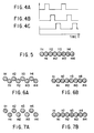
- the ink jet heads 1 and 2 are each arranged to provide drive voltage waveforms to their respective ink chambers at the times indicated in FIGS. 4A, 4B and 4C, thus performing three-phase driving. That is, the ink jet head 1 allows the ink nozzles 41, 44, 47, etc. on the line 1a to project droplets of ink at the time shown in FIG. 4A, the nozzles 42, 45, 48, etc. on the line 1b to project droplets of ink at the time shown in FIG. 4B, and the nozzles 43, 46, 49, etc. on the line 1c to project droplets of ink at the time shown in FIG. 4C.
- the ink jet head 2 allows the ink nozzles 51, 54, 57, etc.
- the ink jet head 1 when a line of printing is made with the recording head, the ink jet head 1 first prints dots n1, n2, n3, n4, ⁇ shown in FIG. 5 through the three-phase driving and the ink jet head 2 then prints dots m1, m2, m3, m4, ⁇ through the three-phase driving, so that one line can be printed at dot pitch P in the main scanning direction. That is, the ink jet heads 1 and 2, while each having a dot pitch of 2P in the main scanning direction, can make printing at twice the resolution determined by that dot pitch.
- a dot line printed by the head 1 can be superimposed upon a dot line by the head 2 because the timing of application of the drive voltages shown in FIGS. 4A, 4B and 4C are determined based on the pitch D in the sub-scanning direction. In this case, there is no problem. However, in practice misalignment occur between dot lines by the heads 1
- the difference ( d - n ⁇ 3D ) is classified into the following three ranges: -D/6 ⁇ d - n ⁇ 3D ⁇ D/6 D/6 ⁇ d - n ⁇ 3D ⁇ 3D/6 3D/6 ⁇ d - n ⁇ 3D ⁇ 5D/6
- the difference (d - n 3D) in the range defined by (1) is within the normal range of error accepted when dots are printed by the ink jet heads alone. In this case, printing can be made at the predetermined times. However, when the difference is in the range defined by (2) or (3), some corrections are required because it is outside the normal range of error.
- misalignment takes place between an arrangement of dots n1, n2, n3, n4, ⁇ printed by the head 1 and an arrangement of dots m1, m2, m3, m4, ⁇ printed by the head 2 as shown in FIG. 6A.
- the ink projecting operation of the ink nozzles 41, 44, 47, etc. on the line 1a of the head 1 and the ink nozzles 52, 55, 58, etc. on the line 2b of the head 2 is performed at the time shown in FIG. 4A
- the ink projecting operation of the ink nozzles 42, 45, 48, etc. on the line 1b of the head 1 and the ink nozzles 53, 56, 59, etc. on the line 2c of the head 2 is performed at the time shown in FIG. 4B
- the ink projecting operation of the ink nozzles 41, 44, 47, etc. on the line 1a of the head 1 and the ink nozzles 53, 56, 59, etc. on the line 2c of the head 2 is performed at the time shown in FIG. 4A
- the ink projecting operation of the ink nozzles 42, 45, 48, etc. on the line 1b of the head 1 and the ink nozzles 51, 54, 57, etc. on the line 2a of the head 2 is performed at the time shown in FIG. 4B
- a head driving method that allows the timing of the projecting of ink to be changed in the manner described above can be implemented by a drive circuit shown in FIG. 8.
- electrodes for applying voltages to ink chambers 111, 112, 113, 114, 115, 116, ⁇ in the ink jet head 1 are connected to ground through analog switches 121, 122, 123, 124, 125, 126, ⁇ , respectively.
- the electrodes for applying voltages to the ink chambers 111, 114, ⁇ equipped with the ink nozzles 41, 44, ⁇ arranged on the line 1a of the ink jet head 1 are connected to a line 31 through analog switches 131, 134, ⁇ , respectively.
- the electrodes for applying voltages to the ink chambers 112, 115, ⁇ equipped with the ink nozzles 42, 45, ⁇ arranged on the line 1b of the ink jet head 1 are connected to a line 31 through analog switches 132 135, ⁇ , respectively.
- the electrodes for applying voltages to the ink chambers 113, 116, ⁇ equipped with the ink nozzles 43, 46, ⁇ arranged on the line 1c of the ink jet head 1 are connected to a line 33 through analog switches 133, 136, ⁇ , respectively.
- Electrodes for applying voltages to ink chambers 211, 212, 213, 214, 215, ⁇ in the ink jet head 2 are connected to ground through analog switches 221, 222, 223, 224, 225, ⁇ , respectively.
- the electrodes for applying voltages to the ink chambers 211, 214, ⁇ equipped with the ink nozzles 51, 54, ⁇ arranged on the line 2a of the ink jet head 2 are connected to a line 34 through analog switches 231, 234, ⁇ , respectively.
- the electrodes for applying voltages to the ink chambers 212, 215, ⁇ equipped with the ink nozzles 52, 55, ⁇ arranged on the line 2b of the ink jet head 2 are connected to a line 35 through analog switches 232, 235, ⁇ , respectively.
- the electrodes for applying voltages to the ink chambers 213, ⁇ equipped with the ink nozzles 53, ⁇ arranged on the line 2c of the ink jet head 2 are connected to a line 36 through analog switches 233, ⁇ , respectively.
- the line 31 is connected to a waveform generator 37 for generating the drive voltage waveform shown in FIG. 4A and to each of first terminals 40a, 41a and 42a of selectors 40, 41 and 42.
- the line 32 is connected to a waveform generator 38 for generating the drive voltage waveform shown in FIG. 4B and to each of second terminals 40b, 41b and 42b of the selectors 40, 41 and 42.
- the line 33 is connected to a waveform generator 39 for generating the drive voltage waveform shown in FIG. 4C and to each of third terminals 40c, 41c and 42c of the selectors 40, 41 and 42.
- the line 34 is connected to the common terminal of the selector 40.
- the line 35 is connected to the common terminal of the selector 41.
- the line 36 is connected to the common terminal of the selector 42.
- the head drive circuit Based on data to be printed from a printing data output circuit 43, the head drive circuit selectively turns on the analog switches 121 to 126 or 221 to 225 to thereby connect the electrodes of the ink chambers associated with the selectively turned-on analog switches to ground.
- the head drive circuit selectively turns on the analog switches 131 to 136 or 231 to 235 to thereby selectively apply the drive voltage waveform shown in FIG. 4A, 4B or 4C to each of the electrodes of the ink chambers associated with the selectively turned-on analog switches.
- the analog switches 131 to 135 or 231 to 235 are selectively driven, droplets of ink are projected from the nozzles of the corresponding ink chambers.
- the selective application of the drive voltage waveform in FIG. 4A, 4B or 4C to each of the ink chamber electrodes is performed through the selectors 40, 41, and 42. That is, when the difference (d - n 3D) is in the range defined by (1), the selector 40 selects the drive voltage waveform from the waveform generator 37 and outputs it onto the line 34.
- the selector 41 selects the drive voltage waveform from the waveform generator 38 and outputs it onto the line 35.
- the selector 42 selects the drive voltage waveform from the waveform generator 39 and outputs it onto the line 36.
- the selector 40 selects the drive voltage waveform from the waveform generator 38 and outputs it onto the line 34.
- the selector 41 selects the drive voltage waveform from the waveform generator 39 and outputs it onto the line 35.
- the selector 42 selects the drive voltage waveform from the waveform generator 37 and outputs it onto the line 36.
- the selector 40 selects the drive voltage waveform from the waveform generator 39 and outputs it onto the line 34.
- the selector 41 selects the drive voltage waveform from the waveform generator 37 and outputs it onto the line 35.
- the selector 42 selects the drive voltage waveform from the waveform generator 38 and outputs it onto the line 36.
- Such control allows the alignment error between dot arrangements produced by the ink jet heads 1 and 2 in the sub-scanning direction to be corrected. That is, the dot misalignment in the sub-scanning direction is minimized, allowing high-resolution printing of good quality.
- a method of detecting the difference (d - n 3D) involves making printing in a specific pattern for testing as shown in FIG. 9A, observing the result of printing with a microscope, and measuring the spacing L between a line of dots n1, n2, ⁇ printed by the ink jet head 1 and a line of dots m1, m2, ⁇ printed by the ink jet head 2.
- a testing specific pattern having a constant spacing may be printed and the spacing L between a line of dots m1, m2, ⁇ and the specific pattern may be determined.
- FIGS. 10 through 13 a second embodiment of the present invention will be described with reference to FIGS. 10 through 13.
- like reference numerals are used to denote corresponding parts to those in the first embodiment and only different parts will be described.
- the waveform generators 37, 38 and 39 and the selectors 40, 41 and 42 in the first embodiment are replaced with programmable waveform generators 51 to 56.
- the programmable waveform generator 51 supplies its drive voltage waveform to analog switches 131, 134, etc.
- the programmable waveform generator 52 supplies its drive voltage waveform to the analog switches 132, 135, etc.
- the programmable waveform generator 53 supplies its drive voltage waveform to the analog switches 133, 136, etc.
- the programmable waveform generator 54 supplies its drive voltage waveform to the analog switches 231, 234, etc.
- the programmable waveform generator 55 supplies its drive voltage waveform to the analog switches 232, 235, etc.
- the programmable waveform generator 56 supplies its drive voltage waveform to the analog switches 233, etc.
- the programmable waveform generators 51 to 56 are set in advance to vary the timing of their respective drive voltage waveform according to the differences (d - n 3D) defined by (1), (2) and (3).
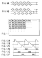
- FIG. 11 shows an arrangement of printed dot data, in which d11, d21, d31, d41, d51, ⁇ , d13, d23, d33, d43, d53, ⁇ , d15, d25, d35, d45, d55, ⁇ are printed by the ink jet head 1, and d12, d22, d32, d42, d52, ⁇ , d14, d24, d34, d44, d54, ⁇ , d16, d26, d36, d46, d56, ⁇ are printed by the ink jet head 2.
- the head 1 drives the ink chambers 111, 114, ⁇ with a drive voltage waveform shown in FIG. 12A, which results in printed dot data d11, d21, d31, ⁇ as shown in FIG. 12D.
- the ink chambers 112, 115, ⁇ are driven with a drive voltage waveform shown in FIG. 12B, resulting in printed dot data d13, d23, ⁇ as shown in FIG. 12E.
- the ink chambers 113, 116, ⁇ are driven with a drive voltage waveform shown in FIG. 12C, resulting in printed dot data d15, d25, ⁇ as shown in FIG. 12F.
- the head 2 drives the ink chambers 212, 215, ⁇ with a drive voltage waveform shown in FIG. 13A, which results in printed dot data d14, d24, d34, ⁇ as shown in FIG. 13E.
- the ink chambers 213, ⁇ are driven with a drive voltage waveform shown in FIG. 13B, resulting in printed dot data d26, d36, ⁇ as shown in FIG. 13F.
- the ink chambers 211, 214, ⁇ are driven with a drive voltage waveform shown in FIG. 13C, resulting in printed dot data d12, d22, d32, ⁇ as shown in FIG. 13D.
- the second embodiment also allows misalignment in the sub-scanning direction between dot arrangements produced by the heads 1 and 2 to be corrected. That is, the dot misalignment in the sub-scanning direction is minimized, allowing high-resolution printing of good quality.
- ink jet heads 61 and 62 each have a third embodiment of the present invention.
- ink jet heads 61 and 62 each have a third embodiment of the present invention.
- the ink jet heads 61 and 62 are provided with ink nozzles 641 to 6410, ⁇ , 651 to 659, ⁇ each of which is associated with a respective one of the ink chambers. These nozzles are placed in a staggered arrangement for every five nozzles.
- the ink nozzles 641 to 6410 are arranged at regular intervals of pitch 2P in the main scanning direction perpendicular to the direction indicated by an arrow in which a recording medium moves.
- the ink chambers are divided into five sets each including every fifth chamber. That is, the ink nozzles 641, 646, etc. form a first set.
- the nozzles 642, 647, etc. form a second set.
- the nozzles 643, 648, etc. form a third set.
- the nozzles 644, 649, etc. form a fourth set.
- the nozzles 645, 6410, etc. form a fifth set.
- the ink nozzles 642, 647, etc. in the second set are arranged on a line 1e which is offset from the line 1d by given pitch D in the sub-scanning direction in which the recording medium travels.
- the ink nozzles 643, 648, etc. in the third set are arranged on a line 1f offset from the line 1e by the pitch D in the sub-scanning direction.
- the ink nozzles 644, 649, etc. in the fourth set are arranged on a line 1g offset from the line 1f by the pitch D in the sub-scanning direction.
- the ink nozzles 645, 6410, etc. in the fifth set are arranged on a line 1h offset from the line 1g by the pitch D in the sub-scanning direction.
- each of the nozzles 651 to 659, etc. which are arranged at regular intervals of pitch 2P in the main scanning direction, is offset from a corresponding one of the nozzles 641 to 649, etc. by pitch P in the main scanning direction.
- the ink chambers are divided into five sets each including every fifth chamber. That is, the ink nozzles 651, 666, etc. form a first set.
- the nozzles 652, 657, etc. form a second set.
- the nozzles 653, 658, etc. form a third set.
- the nozzles 654, 659, etc. form a fourth set.
- the nozzles 655, etc. form a fifth set.
- the ink nozzles 652, 657, etc. in the second set are arranged on a line 2e offset from the line 2d by given pitch D in the sub-scanning direction in which the recording medium travels.
- the ink nozzles 653, 658, etc. in the third set are arranged on a line 2f offset from the line 2e by the pitch D in the sub-scanning direction.
- the ink nozzles 654, 659, etc. in the fourth set are arranged on a line 2g offset from the line 2f by the pitch D in the sub-scanning direction.
- the ink nozzles 655, etc. in the fifth set are arranged on a line 2h offset from the line 2g by the pitch D in the sub-scanning direction.
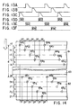
- the ink jet heads 61 and 62 are each arranged to provide drive voltage waveforms to their respective ink chambers at the times indicated in FIGS. 15A to 15F, thus performing five-phase driving. That is, the ink nozzles 641, 646, etc. on the line 1d of the head 61 and the ink nozzles 651, 656, etc. on the line 2d of the head 62 are allowed to project droplets of ink at the times indicated in FIG. 15A.
- the ink nozzles 642, 647, etc. on the line 1e of the head 61 and the ink nozzles 652, 657, etc. on the line 2e of the head 62 project droplets of ink at the times indicated in FIG. 15B.
- the ink nozzles 644, 649, etc. on the line 1g of the head 61 and the ink nozzles 654, 659, etc. on the line 2g of the head 62 project droplets of ink at the times indicated in FIG. 15D.
- the ink nozzles 645, 6410, etc. on the line 1h of the head 61 and the ink nozzles 655, etc. on the line 2h of the head 62 project droplets of ink at the times indicated in FIG. 15E.
- the ink jet head 61 prints dots n1, n2, n3, n4, ⁇ as in FIG. 5 through the three-phase driving and the ink jet head 62 prints dots m1, m2, m3, m4, ⁇ through the three-phase driving, so that one line can be printed at dot pitch P in the main scanning direction. That is, the ink jet heads 61 and 62, while each having a dot pitch of 2P in the main scanning direction, can make printing at twice the resolution determined by that dot pitch.
- a dot line printed by the head 61 can be superimposed upon a dot line by the head 62 because the timing of application of the drive voltage waveforms shown in FIGS. 15A to 15E are determined based on the pitch D in the sub-scanning direction. In this case, there is no problem. In practice, however, misalignment will occur between the dot lines printed by the heads 61 and 62 due to irregularities in the thickness of the substrate 63 and/or the adhesive layer.
- the accuracy of printing position can be increased in comparison with the above-described embodiments in which the ink nozzles are staggered for every three nozzles.
- the printing speed becomes slower than in the three-phase driving.
- the choice of the three-phase driving or the five-phase driving depends on tradeoff between the printing speed and the accuracy of printing position.
- 71, 72 and 73 denote ink jet heads for projecting cyan ink, magenta ink, and yellow ink, respectively.
- the cyan ink jet head 71 and the magenta ink jet head 72 are attached to both sides of a substrate 74 with adhesive, and the magenta ink jet head 72 and the yellow ink jet head 73 are attached to both sides of a substrate 75 with adhesive, thereby forming one color print head assembly.
- the ink jet heads 71, 72 and 73 are formed with ink nozzles 761 to 769, ⁇ , 771 to 779, ⁇ , and 781 to 789, ⁇ each of which is associated with a respective one of ink chambers.
- These ink nozzles are placed in a staggered arrangement for every three nozzles. That is, the ink nozzles 761 to 769, ⁇ of the ink jet head 71 are arranged at regular intervals of pitch P in the main scanning direction perpendicular to the direction of movement of the recording medium indicated by an arrow.
- the ink chambers are divided into three sets each including every third head. That is, the ink nozzles 761, 764, 767, etc. form a first set.
- the nozzles 762, 765, 768, etc. form a second set, and the nozzles 763, 766, 769, etc. form a third set.
- the ink nozzles 761, 764, 767, etc. in the first set to which reference is made are arranged on a line ca.
- the ink nozzles 762, 765, 768, etc. in the second set are arranged on a line cb which is offset from the line ca by given pitch D in the sub-scanning direction.
- the ink nozzles 763, 766, 769, etc. in the third set are arranged on a line cc which is offset from the line cb by the pitch D in the sub-scanning direction.
- the ink chambers are divided into three sets each including every third head. That is, the ink nozzles 771, 774, 777, etc. form a first set. The nozzles 772, 775, 778, etc. form a second set, and the nozzles 773, 776, 779, etc. form a third set.
- each of the nozzles 781 to 789, etc. which are arranged at regular intervals of pitch P in the main scanning direction, is aligned with a corresponding one of the nozzles 761 to 769, etc. in the head 71 in the sub-scanning direction.
- the ink nozzles 781, 784, 787, etc. in the first set are arranged on a line ya which is spaced apart from the reference line ca by distance d2 in the sub-scanning direction.
- the ink nozzles 782, 785, 788, etc. in the second set are arranged on a line yb offset from the line ya by given pitch D in the sub-scanning direction.
- the ink nozzles 783, 786, 789, etc. in the third set are arranged on a line yc offset from the line yb by the pitch D in the sub-scanning direction.
- the ink jet heads 71, 72 and 73 are each arranged to provide drive voltage waveforms to their respective ink chambers at the times indicated in FIGS. 4A, 4B and 4C as in the first embodiment, thus performing three-phase driving. That is, the ink nozzles 761, 764, 767, etc. on the line ca of the head 71, the ink nozzles 771, 774, 777, etc. on the line ma of the head 72 and the ink nozzles 781, 786, 787, etc. on the line ya of the head 73 project ink at the times indicated in FIG. 4A.
- the ink nozzles 763, 766, 769, etc. on the line cc of the head 71, the ink nozzles 773, 776, 779, etc. on the line mc of the head 72 and the ink nozzles 783, 786, 789, etc. on the line yc of the head 73 project ink at the times indicated in FIG. 4C.
- the ink jet head 71 is first three-phase driven to print dots, the head 72 is then three-phase driven to print selectively dots on the printed dots by the head 71, and the head 73 is finally three-phase driven to print selectively dots on the printed dots by the heads 71 and 72.
- color printing is made by printing three colored dots of cyan, magenta, and yellow independently or superimposed upon each other.
- misalignment will occur among the cyan dots, the magenta dots, and the yellow dots. That is, such misalignment of dots as shown in FIG. 19A is produced.
- the misalignment of dots is measured in the same way as that of the first embodiment described in connection with FIGS. 9A and 9B.
- the position of each dot in the sub-scanning direction is adjusted and the dot misalignment is minimized by varying the order allocated for the lines of the head 72 and/or head 73 to project ink.
- the cyan, magenta and yellows dots can become superimposed accurately as shown in FIG. 19B, achieving color printing of good quality.
- ink jet heads 811 to 81n each having a large number of ink chambers arranged are staggered on either side of a substrate 82 to form an elongate line print head assembly.
- This line print head assembly is placed so that its longitudinal line coincides with the main scanning direction perpendicular to the direction in which a recording medium moves and makes printing onto the recording medium on a line by line basis.
- each of the ink jet heads 811 to 81n of the line print head assembly as in the ink jet heads 1 and 2 in the first embodiment, the ink nozzles are staggered for every three nozzles and the ink chambers are divided into three sets each including every third chamber.
- each of lines of ink nozzles 83 in the head 811 and the corresponding line of ink nozzles 84 of the head 813 placed on the same side as the head 81 may be offset from each other by ⁇ d in the sub-scanning direction.
- the line offset can be corrected by making the timing of projecting of ink from each set of ink nozzles in the head 813 differ from the timing of projecting of ink from the corresponding set of ink nozzles in the head 811. That is, as described previously in the first embodiment, the position offset in the sub-scanning direction is corrected by changing the order in which the drive voltage waveforms shown in FIGS. 4A, 4B and 4C are selected, i.e., by changing the timing of ink projection. The position offset in the sub-scanning direction of the ink nozzles of the heads 811 and 812 that are placed on the opposed surfaces of the substrate 82 can be corrected through exactly the same control as in the first embodiment.
- FIGS. 22 and 23 A sixth embodiment of the present invention will be described next with reference to FIGS. 22 and 23.
- ink jet heads 851 to 85n each equipped with a large number of ink chambers are arranged side by side on the same side of a substrate 86 and fixed to the substrate with adhesive, thereby forming an elongate line print head assembly.
- This line print head assembly is placed so that its longitudinal line coincides with the main scanning direction perpendicular to the direction in which a recording medium moves and makes printing onto the recording medium on a line by line basis.
- each of the ink jet heads 851 to 85n of the line print head assembly as in the ink jet heads 1 and 2 in the first embodiment, the ink nozzles are staggered for every three nozzles and the ink chambers are divided into three sets each including every third chamber.
- each of lines of ink nozzles 86 in the head 851 and the corresponding line of ink nozzles 87 of the head 852 may be offset from each other by ⁇ d in the sub-scanning direction.
- the line offset can be corrected by making the timing of projecting of ink from each set of ink nozzles in the head 852 differ from the timing of projecting of ink from the corresponding set of ink nozzles in the head 851. That is, as described previously in the first embodiment, the position offset in the sub-scanning direction is corrected by changing the order in which the drive voltage waveforms shown in FIGS. 4A, 4B and 4C are selected, i.e., by changing the timing of ink projection.
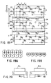
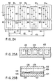
- a seventh embodiment of the present invention will be described next with reference to FIG. 24.
- ink jet heads 911, 912, 913 and 914 are arranged such that they are in parallel with each other in the direction indicated by an arrow in which a recording medium moves, i.e., in the sub-scanning direction and are spaced apart from each other by predetermined distance in the main scanning direction perpendicular to the direction in which the recording medium moves, thereby forming a serial print head assembly.
- the ink nozzles are staggered for every three nozzles and the ink chambers are divided into three sets each including every third chamber.
- a line 1i on which a first set of ink nozzles 92 in the leftmost head 911 are arranged a line 2i on which a first set of ink nozzles 93 of the head 912 are arranged is spaced apart by distance d1 from the line 1i.
- a line 3i on which a first set of ink nozzles 94 of the head 913 are arranged is spaced apart by distance d2 from the line 1i.
- a line 4i on which a first set of ink nozzles 95 of the head 914 are arranged is offset by distance d3 from the line 1i.
- This type of serial print head assembly is arranged to move in the main scanning direction with a recording medium stopped to thereby print multiple lines of dots at a time.
- the print head assembly forms a color serial print head when the heads 911, 912, 913 and 914 are used as heads for cyan, magenta, yellow, and black, respectively.
- the order in which the drive voltage waveforms shown in FIGS. 4A, 4B and 4C are selected can be changed as in the first embodiment, i.e., the timing of ink projection from the ink nozzles can be changed for each set of ink nozzles in the heads 911, 912 and 913 to correct the registration error of dots in the main scanning direction.
- FIGS. 25A and 25B show an ink jet head of the type that heats ink in the ink chambers and then projects it.
- Grooves of U-shaped cross section are formed in one surface of a substrate 101 at predetermined pitch.
- the grooves are covered on top with a board 102 and covered in front with an orifice plate 104 formed with ink nozzles 103, thus forming a large number of ink chambers 105.
- a heating element 106 and electrode patterns 107 and 108 for energizing the heating element which, in turn, are covered with a protective coating 109.
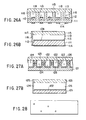
- FIGS. 26A and 26B show an ink jet head of the type that ejects ink within ink chambers by mechanical vibrations of a piezoelectric material.
- Grooves of U-shaped cross section are formed in one surface of a substrate 111 made of a piezoelectric material, when an actuator that is polarized in the direction of an arrow is formed in the middle of each groove.
- Electrode patterns 113 and 114 are formed on the opposed surfaces of the actuator.
- the grooves are covered on top with a board 115 and covered in front with an orifice plate 117 formed with ink nozzles 116, thus forming a large number of ink chambers 118.
- FIGS. 27A and 27B show an ink jet head of the type that ejects ink by mechanical vibrations of piezoelectric elements.
- Two polarized piezoelectric elements are glued together with their directions of polarization opposed to each other to form a substrate 121.
- U-shaped grooves are formed at predetermined pitch in one surface of the substrate across the two piezoelectric elements.
- An electrode pattern 122 is formed on the sidewalls and the bottom of each groove.
- the grooves are covered on top with a board 123 and covered in front with an orifice plate 125 formed with ink nozzles 124, thus forming a large number of ink chambers 126.
- the previously described staggered arrangements of ink nozzles may include such an arrangement as shown in FIG. 28.
Applications Claiming Priority (2)
| Application Number | Priority Date | Filing Date | Title |
|---|---|---|---|
| JP04579398A JP4028067B2 (ja) | 1998-02-26 | 1998-02-26 | 記録ヘッドの駆動方法 |
| JP4579398 | 1998-02-26 |
Publications (2)
| Publication Number | Publication Date |
|---|---|
| EP0938976A1 true EP0938976A1 (de) | 1999-09-01 |
| EP0938976B1 EP0938976B1 (de) | 2004-04-14 |
Family
ID=12729171
Family Applications (1)
| Application Number | Title | Priority Date | Filing Date |
|---|---|---|---|
| EP99103374A Expired - Lifetime EP0938976B1 (de) | 1998-02-26 | 1999-02-22 | Ansteuerungsverfahren für einen Aufzeichnungskopf |
Country Status (7)
| Country | Link |
|---|---|
| US (1) | US6533379B1 (de) |
| EP (1) | EP0938976B1 (de) |
| JP (1) | JP4028067B2 (de) |
| KR (1) | KR100286506B1 (de) |
| CN (1) | CN1108927C (de) |
| DE (1) | DE69916354T2 (de) |
| SG (1) | SG74706A1 (de) |
Cited By (14)
| Publication number | Priority date | Publication date | Assignee | Title |
|---|---|---|---|---|
| EP1016524A3 (de) * | 1998-12-28 | 2000-11-22 | Canon Kabushiki Kaisha | Druckkopf, Druckvorrichtung und Ansteuerungsverfahren für einen Druckkopf |
| EP1013423A3 (de) * | 1998-12-21 | 2000-12-06 | Canon Kabushiki Kaisha | Tintenstrahldruckkopf und damit versehene Druckvorrichtung |
| EP1048465A3 (de) * | 1999-04-27 | 2001-03-28 | Hewlett-Packard Company | Verbesserter Druckkopf |
| US6464335B2 (en) | 2000-06-15 | 2002-10-15 | Brother Kogyo Kabushiki Kaisha | Ink jet printer for reducing dot shift |
| EP1301351A1 (de) * | 2000-06-30 | 2003-04-16 | Silverbrook Research Pty. Limited | Steuerung der ausstosszeiten der druckkopfdüsen |
| EP1392091A2 (de) * | 2002-08-20 | 2004-02-25 | Xerox Corporation | Verfahren und System zum Drucken von integrierten Schaltungsplänen |
| EP1826006A1 (de) * | 2006-02-27 | 2007-08-29 | Toshiba Tec Kabushiki Kaisha | Verfahren und Vorrichtung zur Ansteuerung eines Tintenstrahldruckers |
| EP1870239A3 (de) * | 2006-06-22 | 2008-09-24 | Electronics for Imaging, Inc. | Vorrichtung und Verfahren zum Tintenstrahldrucken im Vollbreitenformat |
| US8172363B2 (en) | 2006-06-22 | 2012-05-08 | Electronics For Imaging, Inc. | Apparatus and methods for full-width wide format inkjet printing |
| US9193183B2 (en) | 2007-04-23 | 2015-11-24 | Inca Digital Printers Limited | Large-scale inkjet printer |
| CN106313906A (zh) * | 2015-06-23 | 2017-01-11 | 山东新北洋信息技术股份有限公司 | 热转印打印机及其控制方法 |
| EP3147121A1 (de) * | 2015-08-07 | 2017-03-29 | Canon Kabushiki Kaisha | Aufzeichnungsvorrichtung, aufzeichnungsverfahren und programm |
| CN107206808A (zh) * | 2015-04-23 | 2017-09-26 | 惠普发展公司,有限责任合伙企业 | 打印系统 |
| WO2022053257A1 (en) * | 2020-09-09 | 2022-03-17 | Memjet Technology Limited | Method and print chip for single-pass monochrome printing at high speeds |
Families Citing this family (28)
| Publication number | Priority date | Publication date | Assignee | Title |
|---|---|---|---|---|
| CN1715053B (zh) * | 2000-06-30 | 2010-05-26 | 西尔弗布鲁克研究有限公司 | 具有在逻辑上编组的喷嘴的打印头 |
| JP4617544B2 (ja) * | 2000-07-25 | 2011-01-26 | ソニー株式会社 | プリンタ及びプリンタヘッド |
| JP3891164B2 (ja) | 2003-10-15 | 2007-03-14 | セイコーエプソン株式会社 | 吐出装置 |
| US7364278B2 (en) | 2004-03-03 | 2008-04-29 | Fujifilm Corporation | Inkjet recording apparatus |
| JP3969428B2 (ja) * | 2004-03-03 | 2007-09-05 | 富士フイルム株式会社 | インクジェット記録装置及びインクジェット記録方法 |
| JP3969429B2 (ja) * | 2004-03-08 | 2007-09-05 | 富士フイルム株式会社 | 液吐出装置及び打滴制御方法 |
| US7252372B2 (en) | 2004-03-08 | 2007-08-07 | Fujifilm Corporation | Liquid ejection apparatus and ejection control method |
| JP2005279968A (ja) * | 2004-03-26 | 2005-10-13 | Fuji Photo Film Co Ltd | 液滴吐出ヘッド及び画像形成装置 |
| US7731332B2 (en) | 2004-06-29 | 2010-06-08 | Fujifilm Corporation | Ejection head, image forming apparatus and image forming method |
| KR100636195B1 (ko) | 2004-11-20 | 2006-10-19 | 삼성전자주식회사 | 프린터헤드의 구동 방법 및 그를 이용한 화상 형성 장치. |
| US20060170730A1 (en) * | 2004-12-15 | 2006-08-03 | Rogers Robert E | Print head system minimizing stitch error |
| JP4487826B2 (ja) * | 2005-03-30 | 2010-06-23 | 富士フイルム株式会社 | 液滴吐出ヘッド、液滴吐出装置、及び画像記録方法 |
| KR100682061B1 (ko) * | 2005-05-27 | 2007-02-15 | 삼성전자주식회사 | 화상형성장치 및 화상 형성 방법 |
| US7780275B2 (en) * | 2005-07-13 | 2010-08-24 | Fujifilm Corporation | Image forming apparatus and droplet ejection control method |
| JP4764690B2 (ja) * | 2005-09-27 | 2011-09-07 | 富士フイルム株式会社 | 画像形成装置 |
| JP5055826B2 (ja) * | 2006-05-09 | 2012-10-24 | 富士ゼロックス株式会社 | 画像記録装置 |
| US7828412B2 (en) * | 2006-09-08 | 2010-11-09 | Electronics For Imaging, Inc. | Ink jet printer |
| US8100507B2 (en) * | 2006-09-27 | 2012-01-24 | Electronics For Imaging, Inc. | Industrial ink jet printer |
| WO2008039532A2 (en) * | 2006-09-27 | 2008-04-03 | Electronics For Imaging, Inc. | Sonic leak testing on ink delivery stystems and ink jet heads |
| JP4479732B2 (ja) * | 2007-01-30 | 2010-06-09 | ブラザー工業株式会社 | インクジェット記録装置 |
| US8260944B2 (en) * | 2007-09-07 | 2012-09-04 | International Business Machines Corporation | Using a state machine embedded within a session initiation protocol (SIP) servlet to implement an application programming interface (API) |
| JP5334289B2 (ja) * | 2008-09-30 | 2013-11-06 | 富士フイルム株式会社 | 液滴吐出装置及び画像形成装置 |
| JP2011037016A (ja) * | 2009-08-06 | 2011-02-24 | Canon Inc | 記録装置 |
| JP5835313B2 (ja) * | 2013-09-19 | 2015-12-24 | ダイキン工業株式会社 | 成膜装置 |
| NL2020081B1 (en) * | 2017-12-13 | 2019-06-21 | Xeikon Mfg Nv | Digital printing apparatus and method |
| US11872580B2 (en) * | 2018-01-30 | 2024-01-16 | Ford Motor Company | Composite ultrasonic material applicators with embedded shaping gas micro-applicators and methods of use thereof |
| JP7163108B2 (ja) * | 2018-08-28 | 2022-10-31 | 東芝テック株式会社 | 液体吐出装置及び駆動タイミング決定方法 |
| CN109788276B (zh) * | 2018-12-29 | 2020-09-08 | 北京牡丹电子集团有限责任公司数字电视技术中心 | 一种视频亮度色度偏离测试方法及装置 |
Citations (6)
| Publication number | Priority date | Publication date | Assignee | Title |
|---|---|---|---|---|
| EP0005844A1 (de) * | 1978-06-05 | 1979-12-12 | International Business Machines Corporation | Zeilenförmig bewegbare Lese- und Schreibeinrichtung |
| JPS5692076A (en) * | 1979-12-27 | 1981-07-25 | Nec Corp | Printing head for serial printer |
| EP0425285A1 (de) * | 1989-10-26 | 1991-05-02 | Seiko Epson Corporation | Punktdruckkopf für einen seriellen Drucker |
| EP0433556A2 (de) * | 1989-12-21 | 1991-06-26 | Hewlett-Packard Company | Einrichtung und Verfahren zum mehrfarbigen Tintenstrahldruck |
| WO1996032281A2 (en) * | 1995-04-12 | 1996-10-17 | Eastman Kodak Company | Nozzle placement in monolithic drop-on-demand print heads |
| US5644344A (en) * | 1991-10-31 | 1997-07-01 | Hewlett-Packard Company | Optical print cartridge alignment system |
Family Cites Families (10)
| Publication number | Priority date | Publication date | Assignee | Title |
|---|---|---|---|---|
| US4014029A (en) * | 1975-12-31 | 1977-03-22 | International Business Machines Corporation | Staggered nozzle array |
| US4345262A (en) * | 1979-02-19 | 1982-08-17 | Canon Kabushiki Kaisha | Ink jet recording method |
| JPS6277951A (ja) * | 1985-10-01 | 1987-04-10 | Canon Inc | インクジエツト記録方法 |
| US5250956A (en) | 1991-10-31 | 1993-10-05 | Hewlett-Packard Company | Print cartridge bidirectional alignment in carriage axis |
| JPH06171084A (ja) | 1992-02-07 | 1994-06-21 | Seiko Epson Corp | インクジェット記録ヘッド |
| JP3227284B2 (ja) | 1992-10-30 | 2001-11-12 | キヤノン株式会社 | インクジェット記録方法およびインクジェット記録ヘッド |
| DE69330081T2 (de) | 1992-10-30 | 2001-08-30 | Canon Kk | Tintenstrahlaufzeichnungssystem und Vorrichtung |
| JPH07156452A (ja) | 1993-12-02 | 1995-06-20 | Ricoh Co Ltd | インクジェット記録装置 |
| US5929875A (en) * | 1996-07-24 | 1999-07-27 | Hewlett-Packard Company | Acoustic and ultrasonic monitoring of inkjet droplets |
| JP4155472B2 (ja) * | 1996-08-28 | 2008-09-24 | セイコーエプソン株式会社 | 記録方法および記録装置 |
-
1998
- 1998-02-26 JP JP04579398A patent/JP4028067B2/ja not_active Expired - Lifetime
-
1999
- 1999-02-18 US US09/252,444 patent/US6533379B1/en not_active Expired - Lifetime
- 1999-02-22 EP EP99103374A patent/EP0938976B1/de not_active Expired - Lifetime
- 1999-02-22 DE DE69916354T patent/DE69916354T2/de not_active Expired - Lifetime
- 1999-02-24 KR KR1019990006024A patent/KR100286506B1/ko not_active IP Right Cessation
- 1999-02-24 SG SG1999001028A patent/SG74706A1/en unknown
- 1999-02-26 CN CN99102440A patent/CN1108927C/zh not_active Expired - Fee Related
Patent Citations (6)
| Publication number | Priority date | Publication date | Assignee | Title |
|---|---|---|---|---|
| EP0005844A1 (de) * | 1978-06-05 | 1979-12-12 | International Business Machines Corporation | Zeilenförmig bewegbare Lese- und Schreibeinrichtung |
| JPS5692076A (en) * | 1979-12-27 | 1981-07-25 | Nec Corp | Printing head for serial printer |
| EP0425285A1 (de) * | 1989-10-26 | 1991-05-02 | Seiko Epson Corporation | Punktdruckkopf für einen seriellen Drucker |
| EP0433556A2 (de) * | 1989-12-21 | 1991-06-26 | Hewlett-Packard Company | Einrichtung und Verfahren zum mehrfarbigen Tintenstrahldruck |
| US5644344A (en) * | 1991-10-31 | 1997-07-01 | Hewlett-Packard Company | Optical print cartridge alignment system |
| WO1996032281A2 (en) * | 1995-04-12 | 1996-10-17 | Eastman Kodak Company | Nozzle placement in monolithic drop-on-demand print heads |
Non-Patent Citations (1)
| Title |
|---|
| PATENT ABSTRACTS OF JAPAN vol. 005, no. 166 (M - 093) 23 October 1981 (1981-10-23) * |
Cited By (35)
| Publication number | Priority date | Publication date | Assignee | Title |
|---|---|---|---|---|
| US6310639B1 (en) | 1996-02-07 | 2001-10-30 | Hewlett-Packard Co. | Printer printhead |
| US6540325B2 (en) | 1996-02-07 | 2003-04-01 | Hewlett-Packard Company | Printer printhead |
| EP1013423A3 (de) * | 1998-12-21 | 2000-12-06 | Canon Kabushiki Kaisha | Tintenstrahldruckkopf und damit versehene Druckvorrichtung |
| US6371588B1 (en) | 1998-12-21 | 2002-04-16 | Canon Kabushiki Kaisha | Printhead and printing apparatus using printhead |
| EP1016524A3 (de) * | 1998-12-28 | 2000-11-22 | Canon Kabushiki Kaisha | Druckkopf, Druckvorrichtung und Ansteuerungsverfahren für einen Druckkopf |
| US6460976B1 (en) | 1998-12-28 | 2002-10-08 | Canon Kabushiki Kaisha | Printing apparatus having control means of controlling timing for driving blocks of print elements |
| EP1048465A3 (de) * | 1999-04-27 | 2001-03-28 | Hewlett-Packard Company | Verbesserter Druckkopf |
| US6464335B2 (en) | 2000-06-15 | 2002-10-15 | Brother Kogyo Kabushiki Kaisha | Ink jet printer for reducing dot shift |
| EP1301351A4 (de) * | 2000-06-30 | 2004-09-15 | Silverbrook Res Pty Ltd | Steuerung der ausstosszeiten der druckkopfdüsen |
| AU2004214600B2 (en) * | 2000-06-30 | 2006-04-06 | Memjet Technology Limited | A pagewidth printhead defining an array of nozzles with predetermined groupings |
| EP1301351A1 (de) * | 2000-06-30 | 2003-04-16 | Silverbrook Research Pty. Limited | Steuerung der ausstosszeiten der druckkopfdüsen |
| EP1392091A2 (de) * | 2002-08-20 | 2004-02-25 | Xerox Corporation | Verfahren und System zum Drucken von integrierten Schaltungsplänen |
| US7997680B2 (en) | 2002-08-20 | 2011-08-16 | Palo Alto Research Center Incorporated | Method for the printing of homogeneous electronic material with a multi-ejector print head |
| EP1392091A3 (de) * | 2002-08-20 | 2004-12-01 | Xerox Corporation | Verfahren und System zum Drucken von integrierten Schaltungsplänen |
| US6890050B2 (en) | 2002-08-20 | 2005-05-10 | Palo Alto Research Center Incorporated | Method for the printing of homogeneous electronic material with a multi-ejector print head |
| US7303244B2 (en) | 2002-08-20 | 2007-12-04 | Palo Alto Research Center Incorporated | Method for the printing of homogeneous electronic material with a multi-ejector print head |
| US7549719B2 (en) | 2002-08-20 | 2009-06-23 | Palo Alto Research Center Incorporated | Method for the printing of homogeneous electronic material with a multi-ejector print head |
| US8104863B2 (en) | 2002-08-20 | 2012-01-31 | Palo Alto Research Center Incorporated | Method for the printing of homogeneous electronic material with a multi-ejector print head |
| US7963628B2 (en) | 2002-08-20 | 2011-06-21 | Palo Alto Research Center Incorporated | Method for the printing of homogeneous electronic material with a multi-ejector print head |
| US7992958B2 (en) | 2002-08-20 | 2011-08-09 | Palo Alto Research Center Incorporated | Method for the printing of homogeneous electronic material with a multi-ejector print head |
| EP1826006A1 (de) * | 2006-02-27 | 2007-08-29 | Toshiba Tec Kabushiki Kaisha | Verfahren und Vorrichtung zur Ansteuerung eines Tintenstrahldruckers |
| EP1870239A3 (de) * | 2006-06-22 | 2008-09-24 | Electronics for Imaging, Inc. | Vorrichtung und Verfahren zum Tintenstrahldrucken im Vollbreitenformat |
| US8172363B2 (en) | 2006-06-22 | 2012-05-08 | Electronics For Imaging, Inc. | Apparatus and methods for full-width wide format inkjet printing |
| US7673965B2 (en) | 2006-06-22 | 2010-03-09 | Electronics For Imaging, Inc. | Apparatus and methods for full-width wide format inkjet printing |
| US9193183B2 (en) | 2007-04-23 | 2015-11-24 | Inca Digital Printers Limited | Large-scale inkjet printer |
| CN107206808B (zh) * | 2015-04-23 | 2019-07-02 | 惠普发展公司,有限责任合伙企业 | 打印系统 |
| US10471731B2 (en) | 2015-04-23 | 2019-11-12 | Hewlett-Packard Development Company, L.P. | Printing systems |
| CN107206808A (zh) * | 2015-04-23 | 2017-09-26 | 惠普发展公司,有限责任合伙企业 | 打印系统 |
| CN106313906A (zh) * | 2015-06-23 | 2017-01-11 | 山东新北洋信息技术股份有限公司 | 热转印打印机及其控制方法 |
| US9862214B2 (en) | 2015-08-07 | 2018-01-09 | Canon Kabushiki Kaisha | Recording apparatus for reducing discharge position deviation of discharged ink, and recording method for the same |
| EP3147121A1 (de) * | 2015-08-07 | 2017-03-29 | Canon Kabushiki Kaisha | Aufzeichnungsvorrichtung, aufzeichnungsverfahren und programm |
| WO2022053257A1 (en) * | 2020-09-09 | 2022-03-17 | Memjet Technology Limited | Method and print chip for single-pass monochrome printing at high speeds |
| US11772376B2 (en) | 2020-09-09 | 2023-10-03 | Memjet Technology Limited | Sub-row firing method for single-pass monochrome printing at high speeds |
| US11813861B2 (en) | 2020-09-09 | 2023-11-14 | Memjet Technology Limited | Method for single-pass monochrome printing at high speeds |
| US11820139B2 (en) | 2020-09-09 | 2023-11-21 | Memjet Technology Limited | Print chip configured for single-pass monochrome printing at high speeds |
Also Published As
| Publication number | Publication date |
|---|---|
| CN1229728A (zh) | 1999-09-29 |
| US6533379B1 (en) | 2003-03-18 |
| DE69916354D1 (de) | 2004-05-19 |
| SG74706A1 (en) | 2000-08-22 |
| CN1108927C (zh) | 2003-05-21 |
| JP4028067B2 (ja) | 2007-12-26 |
| EP0938976B1 (de) | 2004-04-14 |
| DE69916354T2 (de) | 2005-06-23 |
| KR19990072880A (ko) | 1999-09-27 |
| JPH11240158A (ja) | 1999-09-07 |
| KR100286506B1 (ko) | 2001-03-15 |
Similar Documents
| Publication | Publication Date | Title |
|---|---|---|
| EP0938976B1 (de) | Ansteuerungsverfahren für einen Aufzeichnungskopf | |
| EP1179430B1 (de) | Druckkopf und Verfahren zu dessen Herstellung | |
| EP1027998A2 (de) | Positionsfehlerkorrektur unter Verwendung von Referenzwerten und relativen Korrekturwerten beim Drucken in zwei Richtungen | |
| EP1932673B1 (de) | Flüssigkeitsablassvorrichtung und Verfahren zum Ablassen von Flüssigkeit | |
| JP4765577B2 (ja) | 液滴吐出装置及び液滴吐出方法 | |
| KR20030082893A (ko) | 액체 토출장치 및 액체 토출방법 | |
| EP1405727B1 (de) | Flüssigkeitsausstossvorrichtung und Flüssigkeitsausstossverfahren | |
| EP0820871B1 (de) | Aufzeichnungskopf des Tintenstrahltyps | |
| US6783212B2 (en) | Ink jet head and ink jet recording apparatus | |
| EP0775583B1 (de) | Titenstrahldruckgerät | |
| US9409390B1 (en) | Printing apparatus and control method therefor | |
| WO2006123528A1 (en) | Imaging apparatus | |
| EP0824243B1 (de) | Druckvorrichtung mit Justierung von Zeilendruckköpfen | |
| KR101162369B1 (ko) | 액체 토출 장치 및 액체 토출 방법 | |
| US7066571B2 (en) | Liquid ejection apparatus | |
| KR101042648B1 (ko) | 액체 토출 장치 및 액체 토출 방법 | |
| JP2019195912A (ja) | 記録装置および記録方法 | |
| US6527375B2 (en) | Ink jet recording device capable of controlling impact positions of ink droplets | |
| JP4146208B2 (ja) | インクジェット式記録装置及びインクジェット式記録方法 | |
| JP3603821B2 (ja) | インクジェット式記録装置、及び、その駆動方法 | |
| EP3377323B1 (de) | Tintenstrahldrucker und verfahren zur steuerung des tintenstrahldruckers | |
| JP2004306417A (ja) | 画像形成装置及び画像形成方法 | |
| JPH1081010A (ja) | 記録装置 | |
| WO1999022942A1 (en) | Printer |
Legal Events
| Date | Code | Title | Description |
|---|---|---|---|
| PUAI | Public reference made under article 153(3) epc to a published international application that has entered the european phase |
Free format text: ORIGINAL CODE: 0009012 |
|
| 17P | Request for examination filed |
Effective date: 19990222 |
|
| AK | Designated contracting states |
Kind code of ref document: A1 Designated state(s): DE FR GB |
|
| AX | Request for extension of the european patent |
Free format text: AL;LT;LV;MK;RO;SI |
|
| AKX | Designation fees paid |
Free format text: DE FR GB |
|
| 17Q | First examination report despatched |
Effective date: 20030304 |
|
| GRAP | Despatch of communication of intention to grant a patent |
Free format text: ORIGINAL CODE: EPIDOSNIGR1 |
|
| GRAS | Grant fee paid |
Free format text: ORIGINAL CODE: EPIDOSNIGR3 |
|
| GRAA | (expected) grant |
Free format text: ORIGINAL CODE: 0009210 |
|
| AK | Designated contracting states |
Kind code of ref document: B1 Designated state(s): DE FR GB |
|
| REG | Reference to a national code |
Ref country code: GB Ref legal event code: FG4D |
|
| REF | Corresponds to: |
Ref document number: 69916354 Country of ref document: DE Date of ref document: 20040519 Kind code of ref document: P |
|
| ET | Fr: translation filed | ||
| PLBE | No opposition filed within time limit |
Free format text: ORIGINAL CODE: 0009261 |
|
| STAA | Information on the status of an ep patent application or granted ep patent |
Free format text: STATUS: NO OPPOSITION FILED WITHIN TIME LIMIT |
|
| 26N | No opposition filed |
Effective date: 20050117 |
|
| PGFP | Annual fee paid to national office [announced via postgrant information from national office to epo] |
Ref country code: FR Payment date: 20080208 Year of fee payment: 10 |
|
| REG | Reference to a national code |
Ref country code: FR Ref legal event code: ST Effective date: 20091030 |
|
| PG25 | Lapsed in a contracting state [announced via postgrant information from national office to epo] |
Ref country code: FR Free format text: LAPSE BECAUSE OF NON-PAYMENT OF DUE FEES Effective date: 20090302 |
|
| PGFP | Annual fee paid to national office [announced via postgrant information from national office to epo] |
Ref country code: DE Payment date: 20110216 Year of fee payment: 13 |
|
| PGFP | Annual fee paid to national office [announced via postgrant information from national office to epo] |
Ref country code: GB Payment date: 20110216 Year of fee payment: 13 |
|
| GBPC | Gb: european patent ceased through non-payment of renewal fee |
Effective date: 20120222 |
|
| REG | Reference to a national code |
Ref country code: DE Ref legal event code: R119 Ref document number: 69916354 Country of ref document: DE Effective date: 20120901 |
|
| PG25 | Lapsed in a contracting state [announced via postgrant information from national office to epo] |
Ref country code: GB Free format text: LAPSE BECAUSE OF NON-PAYMENT OF DUE FEES Effective date: 20120222 |
|
| PG25 | Lapsed in a contracting state [announced via postgrant information from national office to epo] |
Ref country code: DE Free format text: LAPSE BECAUSE OF FAILURE TO SUBMIT A TRANSLATION OF THE DESCRIPTION OR TO PAY THE FEE WITHIN THE PRESCRIBED TIME-LIMIT Effective date: 20120901 |