EP0937629B1 - A mudguard bracket assembly - Google Patents
A mudguard bracket assembly Download PDFInfo
- Publication number
- EP0937629B1 EP0937629B1 EP19990300226 EP99300226A EP0937629B1 EP 0937629 B1 EP0937629 B1 EP 0937629B1 EP 19990300226 EP19990300226 EP 19990300226 EP 99300226 A EP99300226 A EP 99300226A EP 0937629 B1 EP0937629 B1 EP 0937629B1
- Authority
- EP
- European Patent Office
- Prior art keywords
- mudguard
- bracket
- bracket assembly
- support member
- assembly
- Prior art date
- Legal status (The legal status is an assumption and is not a legal conclusion. Google has not performed a legal analysis and makes no representation as to the accuracy of the status listed.)
- Expired - Lifetime
Links
- 230000000712 assembly Effects 0.000 description 6
- 238000000429 assembly Methods 0.000 description 6
- JEIPFZHSYJVQDO-UHFFFAOYSA-N iron(III) oxide Inorganic materials O=[Fe]O[Fe]=O JEIPFZHSYJVQDO-UHFFFAOYSA-N 0.000 description 3
- 239000002184 metal Substances 0.000 description 2
- XLYOFNOQVPJJNP-UHFFFAOYSA-N water Substances O XLYOFNOQVPJJNP-UHFFFAOYSA-N 0.000 description 2
- 230000000295 complement effect Effects 0.000 description 1
- 238000010276 construction Methods 0.000 description 1
- 230000000694 effects Effects 0.000 description 1
- 238000011065 in-situ storage Methods 0.000 description 1
- 238000012986 modification Methods 0.000 description 1
- 230000004048 modification Effects 0.000 description 1
- 238000000465 moulding Methods 0.000 description 1
- 229920003023 plastic Polymers 0.000 description 1
- 239000004033 plastic Substances 0.000 description 1
- 230000000717 retained effect Effects 0.000 description 1
- 238000005728 strengthening Methods 0.000 description 1
Images


Classifications
-
- B—PERFORMING OPERATIONS; TRANSPORTING
- B62—LAND VEHICLES FOR TRAVELLING OTHERWISE THAN ON RAILS
- B62D—MOTOR VEHICLES; TRAILERS
- B62D25/00—Superstructure or monocoque structure sub-units; Parts or details thereof not otherwise provided for
- B62D25/08—Front or rear portions
- B62D25/16—Mud-guards or wings; Wheel cover panels
- B62D25/163—Mounting devices
- B62D25/166—Mounting devices by rods or other distance-keeping devices
-
- B—PERFORMING OPERATIONS; TRANSPORTING
- B62—LAND VEHICLES FOR TRAVELLING OTHERWISE THAN ON RAILS
- B62D—MOTOR VEHICLES; TRAILERS
- B62D25/00—Superstructure or monocoque structure sub-units; Parts or details thereof not otherwise provided for
- B62D25/08—Front or rear portions
- B62D25/16—Mud-guards or wings; Wheel cover panels
- B62D25/168—Mud guards for utility vehicles
Definitions
- the present invention relates to a mudguard bracket assembly that is used to fix a mudguard to a support member on a vehicle such that the mudguard is suspended over a wheel of the vehicle.
- Mudguards on commercial or heavy goods vehicles are generally suspended above the vehicle wheels from a pair of spaced tubular arms or bars that project outwards from the vehicle chassis in a direction that is substantially parallel to the vehicle wheel axles.
- Each mudguard is releasably fixed to the support arms by a plurality of bracket assemblies, see for instance DE 3 045 325 A.
- a conventional bracket assembly comprises an elongate upper saddle plate that is seated over the support arm and part of the upper, convex surface of the mudguard, and a lower, flat back plate on the underside of the mudguard.
- the mudguard is effectively sandwiched between the upper saddle plate and the lower back plate, the plates being secured together by nuts and bolts with the mudguard in place on the vehicle.
- each bracket assembly requires six nut and bolt pairs and therefore twelve fixings are required to suspend each mudguard. It will thus be appreciated that it is extremely time consuming to assemble four or more mudguards to a vehicle particularly when one considers that there is restricted access between the wheel and the mudguard.
- the plates of the bracket assembly have a tendency to trap water in wet conditions and since they are generally constructed from metal they often deteriorate and look unsightly as a result of rust.
- each upper saddle plate is replaced by a pair of U-shaped clamping bars that sit over the support arm, pass through apertures in the mudguard and are connected to each end of the back plate.
- the free ends of the U-shaped members are threaded to receive nuts.
- a further known bracket assembly comprises a two-piece metal clamping member that is mounted on the upper surface of the mudguard. It comprises a first portion that is riveted or otherwise connected to the mudguard and which provides a seat for the support arm. A second portion is pivotally connected to the first member and is shaped so as to pass over the support arm and to fasten to the first portion on the opposite side of the arm to the pivot.
- none of the prior designs is particularly aesthetically pleasing or visually complementary to the mudguard design.
- a mudguard bracket assembly for connecting a mudguard to a support member of a vehicle, the assembly comprising a first bracket portion for connection to the support member and a second bracket portion for releasably securing the first bracket portion to the mudguard so that, when assembled, a part of the mudguard lies between the first and second bracket portions, characterised in that the first bracket portion comprises an aperture for receiving the support member and the assembly further comprises a clamping member moveable between a first position in which it projects into said aperture so as, in use, to clamp against the support member and a second position in which it substantially clear of the aperture so as to allow release or receipt of the support arm, at least one of the bracket portions having a raised portion designed to bias the clamping member into said first position when the second bracket portion is securely fastened to the first bracket portion.
- This arrangement provides for a simplified way of assembling a mudguard to a vehicle and provides for improved clamping.
- the improved clamping enables the number of fixings to be reduced in comparison to most existing bracket assembly designs.
- it permits the bracket to be assembled to the mudguard before the mudguard is then mounted on the vehicle. This clearly eliminates the problem of having to insert and tighten fixings with the mudguard in place on the vehicle.
- mounting of the bracket assembly on the mudguard in-situ is relatively simple since no tools are required to secure fixings on the underside of the mudguard.
- the clamping member may be in the form of a hinged member that is integral with first bracket portion.
- the hinged member preferably co-operates with and, during clamping, bears against the projecting element which forms part of the second bracket portion.
- the second bracket portion is a plate with a central raised section that forms the raised portion referred to above.
- the first bracket portion may have a central portion with an aperture that is flanked by end portions with apertures for receiving fixings.
- the second bracket portion preferably has threaded studs that pass through the apertures in the end portions of the first bracket portion.
- the end portions may conveniently have hinged covers that are pivotal about hinges so as to cover the fixing apertures.
- a mudguard assembly comprising a mudguard, a support member and at least one mudguard bracket assembly as defined above.
- figures 1 and 2 show a mudguard 1 for a vehicle wheel, complete with bracket assemblies 2, in the form it is mounted on the vehicle (which is not shown for clarity).
- the mudguard 1 is suspended above the vehicle wheel (not shown) by two spaced tubular support bars 3 that are fixed to the vehicle chassis by a mounting plate 4 and appropriate bolts (not shown). In alternative designs (not shown) the support bars may be welded directly to the vehicle chassis rather than using mounting plates.
- the mudguard 1 is secured to the support bars 3 by two pairs of spaced bracket assemblies 2, each pair being disposed on opposite sides of the vertex of the mudguard 1.
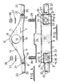
- a bracket assembly 2 is shown in detail in figures 3 to 8 and comprises an upper bracket 5 for receiving the support bar 3 and a lower back plate 6 by which the upper bracket 5 is secured to the mudguard 1.
- the upper bracket 5 is a one-piece substantially hollow plastics moulding having upper, side and end walls 6, 7, 8 that define a central body 9 flanked by terminal feet 10. Strengthening webs (hidden in the drawings) are provided in the hollow between the upper and side walls 6, 7 to ensure that the upper bracket 5 is sufficiently robust and able to take the mudguard load.
- the bottom edge 11 of each side wall 7 is slightly upwardly curved so as to follow the curvature of the mudguard on which the bracket assembly 2 is mounted.
- the upper wall 6 has an arcuate peak 12 and arcuate ramps 13 that extend downwardly on each side to meet an upper surface of the terminal feet 10.
- a transverse circular aperture 14 is provided in the central body 9 for receiving the support bar 3.
- the wall 15 of this aperture 14 is slotted (indicated by reference number 16) as shown in figure 8 to define an arcuate tongue 17 that is hingedly moveable about a line represented by that marked Y-Y in the drawings.
- the underside of the tongue 17 (hidden by the side walls 7 in the drawings) has an integral depending cam follower block 18 that projects below the bottom edge 11 of each side wall 7 as can be seen in figures 4, 6 and 7.
- the terminal feet 10 are each apertured so as to receive fixings and the upper wall 6 is recessed indicated by reference numeral 19 in figures 3 and 5 at each of the terminal feet 10 so as to accommodate those fixings.
- a hood 20 that is connected to each end wall 8 by an integral moulded hinge 21 and is configured so as to be pivoted about the hinge 21 (as indicated by the arrows in figure 6) until it is received in the recess 19.
- the free end of the hood 20 has a projecting lip 22 that is designed to be received in snap-fit engagement with a corresponding aperture 23 provided in an adjacent wall 24 of the recess 19 when the hood 20 is fully received therein.
- the back plate 6 is substantially planar save for a central raised cam platform 25. At each end of the back plate 6, either side of the cam platform 25, there are upstanding threaded studs 26 for engagement with the bracket 5.
- a pair of spaced holes are drilled in the mudguard 1 so as to align with the apertures in the feet 10 of the bracket 5 and the studs 26 on the back plate 6.
- the back plate 6 is then presented to the underside of the mudguard 1 so that the studs 26 pass through the holes drilled in the mudguard 1 and project from the upper surface thereof.
- the back plate 6 is then held in position whilst the bracket 5 is presented to the upper surface of the mudguard 1 so that the projecting studs 26 of the back plate 6 are received in the apertures of the feet 10.
- the assembly is held together by securing a washer 27 and a nut 28 to each stud 26 but at this stage they are not fully tightened.
- cam follower block 18 and tongue 17 are then forced to pivot about the hinge (represented by line Y-Y in figure 8) so that the tongue 17 projects into the central body aperture 14 and applies a clamping force to the support bar 3.
- the hoods 20 are pivoted and snap-engaged in the recesses 19 so as to protect the fixings from the ingress of water or moisture.
- the invention as embodied by the example described above provides for a bracket assembly that is easy to fit to a mudguard and renders the instalment of the mudguard on the vehicle a relatively simple operation.
- the construction of the bracket assembly and in particular the provision of the hoods 20 prevents rusting of the bracket assembly or the fixings.
- the bracket assembly is aesthetically configured so that it complements the appearance of the mudguard.
- the clamping tongue may take any appropriate form that provides for a clamping force to be applied to the support arm when the bracket is fully assembled and tightened in place.
- the tongue may be replaced by a plurality of hinged fingers that are moveable by a cam follower to project into the aperture when the bracket assembly is tightened.
- the tongue and cam follower block may be replaced by a separate sliding chock that is retained between the back plate and the bracket. In this latter embodiment the chock slides upwards into the aperture to bear against the support arm when the bracket assembly is in the clamped configuration.
- the cam platform 25 of the back plate 6 may be replaced by any form of projecting element or raised portion that interacts with the clamping tongue during final assembly.
- the back plate 6 may simply be curved so that the central portion is raised and biases the tongue when the bracket is fully assembled.
Landscapes
- Engineering & Computer Science (AREA)
- Chemical & Material Sciences (AREA)
- Combustion & Propulsion (AREA)
- Transportation (AREA)
- Mechanical Engineering (AREA)
- Body Structure For Vehicles (AREA)
Applications Claiming Priority (2)
| Application Number | Priority Date | Filing Date | Title |
|---|---|---|---|
| GBGB9803612.2A GB9803612D0 (en) | 1998-02-21 | 1998-02-21 | A mudguard bracket assembly |
| GB9803612 | 1998-02-21 |
Publications (3)
| Publication Number | Publication Date |
|---|---|
| EP0937629A2 EP0937629A2 (en) | 1999-08-25 |
| EP0937629A3 EP0937629A3 (en) | 2000-11-22 |
| EP0937629B1 true EP0937629B1 (en) | 2003-12-17 |
Family
ID=10827329
Family Applications (1)
| Application Number | Title | Priority Date | Filing Date |
|---|---|---|---|
| EP19990300226 Expired - Lifetime EP0937629B1 (en) | 1998-02-21 | 1999-01-14 | A mudguard bracket assembly |
Country Status (6)
| Country | Link |
|---|---|
| EP (1) | EP0937629B1 (da) |
| DE (1) | DE69913585T2 (da) |
| DK (1) | DK0937629T3 (da) |
| ES (1) | ES2212463T3 (da) |
| GB (1) | GB9803612D0 (da) |
| PT (1) | PT937629E (da) |
Families Citing this family (3)
| Publication number | Priority date | Publication date | Assignee | Title |
|---|---|---|---|---|
| FI110249B (fi) * | 2000-08-01 | 2002-12-31 | Parlok Ab Oy | Lokasuojan kiinnitysjärjestelmä |
| ITTO20040501A1 (it) * | 2004-07-19 | 2004-10-19 | Lago Accessori S R L | Parafango per autocarri e veicoli similari e relativa staffa di ancoraggio al telaio del veicolo |
| CN107336752B (zh) * | 2017-07-06 | 2020-04-03 | 安徽江山机械有限公司 | 一种多段式弹性挡泥板结构 |
Family Cites Families (6)
| Publication number | Priority date | Publication date | Assignee | Title |
|---|---|---|---|---|
| DE1530623A1 (de) * | 1965-10-05 | 1969-07-03 | Daimler Benz Ag | Lastkraftwagen,insbesondere Sattelzugmaschine |
| DE2921160A1 (de) * | 1979-05-25 | 1980-12-04 | Baetzold & Wagner Baewa | Haltevorrichtung fuer kotfluegel an lastkraftwagen, anhaengern, selbstfahrenden arbeitsmaschinen o.dgl. |
| DE3045325A1 (de) * | 1980-12-02 | 1982-07-01 | BÄWA Bätzold & Wagner, 5608 Radevormwald | Haltevorrichtung fuer kotfluegel an lastkraftwagen, anhaengern oder sonstigen fahrzeugen |
| US4377294A (en) * | 1981-03-17 | 1983-03-22 | Lancaster Colony Corporation | Vehicle fender and support bar |
| FR2556301B1 (fr) * | 1983-12-07 | 1989-04-28 | Fichet Jacques | Garde-boue de vehicule routier |
| DE3925774A1 (de) * | 1989-08-03 | 1991-02-07 | Dunlop Gmbh | Vorrichtung zur halterung von kotfluegeln |
-
1998
- 1998-02-21 GB GBGB9803612.2A patent/GB9803612D0/en not_active Ceased
-
1999
- 1999-01-14 DE DE69913585T patent/DE69913585T2/de not_active Expired - Lifetime
- 1999-01-14 EP EP19990300226 patent/EP0937629B1/en not_active Expired - Lifetime
- 1999-01-14 ES ES99300226T patent/ES2212463T3/es not_active Expired - Lifetime
- 1999-01-14 DK DK99300226T patent/DK0937629T3/da active
- 1999-01-14 PT PT99300226T patent/PT937629E/pt unknown
Also Published As
| Publication number | Publication date |
|---|---|
| ES2212463T3 (es) | 2004-07-16 |
| EP0937629A3 (en) | 2000-11-22 |
| EP0937629A2 (en) | 1999-08-25 |
| GB9803612D0 (en) | 1998-04-15 |
| DE69913585D1 (de) | 2004-01-29 |
| DK0937629T3 (da) | 2004-04-26 |
| PT937629E (pt) | 2004-04-30 |
| DE69913585T2 (de) | 2004-09-30 |
Similar Documents
| Publication | Publication Date | Title |
|---|---|---|
| JP3943237B2 (ja) | ルーフ荷物キャリヤの固定装置 | |
| CA2294437C (en) | Fender having element conforming to mounting bracket | |
| US6010048A (en) | Roof rack with quick release tower assembly | |
| US20050150921A1 (en) | Saddlebag mounting system | |
| CA1091723A (en) | Bracket for removably mounting a mud flap assembly | |
| US8342477B2 (en) | Hinged clamp bracket | |
| EP0941915B1 (en) | Wheel axle suspension for a vehicle with a gas spring system | |
| US8342549B1 (en) | Running board for three wheel motorcycles | |
| US6729053B2 (en) | Bracket for mounting a license plate to a vehicle | |
| US7300085B2 (en) | Motor vehicle safety barrier mounting | |
| EP0937629B1 (en) | A mudguard bracket assembly | |
| US5344187A (en) | Spring strut mounting assembly of a vehicle body | |
| EP2421743B1 (en) | A device for attaching a stay to a vehicle frame and a vehicle comprising the device | |
| EP1479602B1 (en) | Rear fork pads with packing pieces | |
| NL1018676C1 (nl) | Bevestigingssysteem voor een spatbord. | |
| US7900729B2 (en) | Hood adjustment assembly | |
| KR100439804B1 (ko) | 자동차의 시트백 프레임과 시트쿠션 프레임의 조립구조 | |
| EP3623265B1 (en) | A mudguard bracket arrangement and a use of a mudguard bracket arrangement | |
| GB2374058A (en) | Securing a battery in a receptacle on an industrial truck | |
| MXPA05005643A (es) | Unidad de conexion de muelle de hoja. | |
| JP3305609B2 (ja) | 車両用スペアタイヤの支持構造 | |
| WO2016159891A1 (en) | Seat spring structure for motorcycle | |
| WO2008004936A1 (en) | Load carrier foot for clamping a load carrier to a roof of a vehicle | |
| AU671557B2 (en) | A bull-bar assembly | |
| CA1049465A (en) | Wheel and tire carrier for attachment to motor vehicle door |
Legal Events
| Date | Code | Title | Description |
|---|---|---|---|
| PUAI | Public reference made under article 153(3) epc to a published international application that has entered the european phase |
Free format text: ORIGINAL CODE: 0009012 |
|
| AK | Designated contracting states |
Kind code of ref document: A2 Designated state(s): BE DE DK ES FI FR GB GR IE IT LU MC NL PT SE |
|
| AX | Request for extension of the european patent |
Free format text: AL;LT;LV;MK;RO;SI |
|
| PUAL | Search report despatched |
Free format text: ORIGINAL CODE: 0009013 |
|
| AK | Designated contracting states |
Kind code of ref document: A3 Designated state(s): AT BE CH CY DE DK ES FI FR GB GR IE IT LI LU MC NL PT SE |
|
| AX | Request for extension of the european patent |
Free format text: AL;LT;LV;MK;RO;SI |
|
| 17P | Request for examination filed |
Effective date: 20010517 |
|
| AKX | Designation fees paid |
Free format text: BE DE DK ES FI FR GB GR IE IT LU MC NL PT SE |
|
| 17Q | First examination report despatched |
Effective date: 20021114 |
|
| GRAH | Despatch of communication of intention to grant a patent |
Free format text: ORIGINAL CODE: EPIDOS IGRA |
|
| GRAS | Grant fee paid |
Free format text: ORIGINAL CODE: EPIDOSNIGR3 |
|
| GRAA | (expected) grant |
Free format text: ORIGINAL CODE: 0009210 |
|
| AK | Designated contracting states |
Kind code of ref document: B1 Designated state(s): BE DE DK ES FI FR GB GR IE IT LU MC NL PT SE |
|
| REG | Reference to a national code |
Ref country code: GB Ref legal event code: FG4D |
|
| REG | Reference to a national code |
Ref country code: IE Ref legal event code: FG4D |
|
| REF | Corresponds to: |
Ref document number: 69913585 Country of ref document: DE Date of ref document: 20040129 Kind code of ref document: P |
|
| REG | Reference to a national code |
Ref country code: SE Ref legal event code: TRGR |
|
| REG | Reference to a national code |
Ref country code: GR Ref legal event code: EP Ref document number: 20040400863 Country of ref document: GR |
|
| REG | Reference to a national code |
Ref country code: DK Ref legal event code: T3 |
|
| REG | Reference to a national code |
Ref country code: PT Ref legal event code: SC4A Free format text: AVAILABILITY OF NATIONAL TRANSLATION Effective date: 20040311 |
|
| REG | Reference to a national code |
Ref country code: ES Ref legal event code: FG2A Ref document number: 2212463 Country of ref document: ES Kind code of ref document: T3 |
|
| ET | Fr: translation filed | ||
| PLBE | No opposition filed within time limit |
Free format text: ORIGINAL CODE: 0009261 |
|
| STAA | Information on the status of an ep patent application or granted ep patent |
Free format text: STATUS: NO OPPOSITION FILED WITHIN TIME LIMIT |
|
| 26N | No opposition filed |
Effective date: 20040920 |
|
| PGFP | Annual fee paid to national office [announced via postgrant information from national office to epo] |
Ref country code: SE Payment date: 20091218 Year of fee payment: 12 Ref country code: MC Payment date: 20091221 Year of fee payment: 12 |
|
| PGFP | Annual fee paid to national office [announced via postgrant information from national office to epo] |
Ref country code: LU Payment date: 20100120 Year of fee payment: 12 Ref country code: IE Payment date: 20100118 Year of fee payment: 12 |
|
| PGFP | Annual fee paid to national office [announced via postgrant information from national office to epo] |
Ref country code: FI Payment date: 20100114 Year of fee payment: 12 |
|
| PGFP | Annual fee paid to national office [announced via postgrant information from national office to epo] |
Ref country code: PT Payment date: 20101223 Year of fee payment: 13 |
|
| PG25 | Lapsed in a contracting state [announced via postgrant information from national office to epo] |
Ref country code: MC Free format text: LAPSE BECAUSE OF NON-PAYMENT OF DUE FEES Effective date: 20110131 |
|
| REG | Reference to a national code |
Ref country code: SE Ref legal event code: EUG |
|
| REG | Reference to a national code |
Ref country code: IE Ref legal event code: MM4A |
|
| PG25 | Lapsed in a contracting state [announced via postgrant information from national office to epo] |
Ref country code: FI Free format text: LAPSE BECAUSE OF NON-PAYMENT OF DUE FEES Effective date: 20110114 |
|
| PG25 | Lapsed in a contracting state [announced via postgrant information from national office to epo] |
Ref country code: IE Free format text: LAPSE BECAUSE OF NON-PAYMENT OF DUE FEES Effective date: 20110114 |
|
| REG | Reference to a national code |
Ref country code: PT Ref legal event code: MM4A Free format text: LAPSE DUE TO NON-PAYMENT OF FEES Effective date: 20120716 |
|
| PG25 | Lapsed in a contracting state [announced via postgrant information from national office to epo] |
Ref country code: PT Free format text: LAPSE BECAUSE OF NON-PAYMENT OF DUE FEES Effective date: 20120716 |
|
| PGFP | Annual fee paid to national office [announced via postgrant information from national office to epo] |
Ref country code: GR Payment date: 20121214 Year of fee payment: 15 |
|
| PG25 | Lapsed in a contracting state [announced via postgrant information from national office to epo] |
Ref country code: SE Free format text: LAPSE BECAUSE OF NON-PAYMENT OF DUE FEES Effective date: 20110115 |
|
| PG25 | Lapsed in a contracting state [announced via postgrant information from national office to epo] |
Ref country code: LU Free format text: LAPSE BECAUSE OF NON-PAYMENT OF DUE FEES Effective date: 20110114 |
|
| REG | Reference to a national code |
Ref country code: GR Ref legal event code: ML Ref document number: 20040400863 Country of ref document: GR Effective date: 20140801 |
|
| PG25 | Lapsed in a contracting state [announced via postgrant information from national office to epo] |
Ref country code: GR Free format text: LAPSE BECAUSE OF NON-PAYMENT OF DUE FEES Effective date: 20140801 |
|
| REG | Reference to a national code |
Ref country code: FR Ref legal event code: PLFP Year of fee payment: 18 |
|
| REG | Reference to a national code |
Ref country code: FR Ref legal event code: PLFP Year of fee payment: 19 |
|
| PGFP | Annual fee paid to national office [announced via postgrant information from national office to epo] |
Ref country code: ES Payment date: 20161213 Year of fee payment: 19 |
|
| PGFP | Annual fee paid to national office [announced via postgrant information from national office to epo] |
Ref country code: DK Payment date: 20170110 Year of fee payment: 19 |
|
| REG | Reference to a national code |
Ref country code: FR Ref legal event code: PLFP Year of fee payment: 20 |
|
| PGFP | Annual fee paid to national office [announced via postgrant information from national office to epo] |
Ref country code: FR Payment date: 20171211 Year of fee payment: 20 |
|
| PGFP | Annual fee paid to national office [announced via postgrant information from national office to epo] |
Ref country code: BE Payment date: 20171213 Year of fee payment: 20 |
|
| PGFP | Annual fee paid to national office [announced via postgrant information from national office to epo] |
Ref country code: NL Payment date: 20180115 Year of fee payment: 20 |
|
| PGFP | Annual fee paid to national office [announced via postgrant information from national office to epo] |
Ref country code: DE Payment date: 20180103 Year of fee payment: 20 Ref country code: GB Payment date: 20180110 Year of fee payment: 20 |
|
| PGFP | Annual fee paid to national office [announced via postgrant information from national office to epo] |
Ref country code: IT Payment date: 20180122 Year of fee payment: 20 |
|
| REG | Reference to a national code |
Ref country code: DK Ref legal event code: EBP Effective date: 20180131 |
|
| REG | Reference to a national code |
Ref country code: DE Ref legal event code: R071 Ref document number: 69913585 Country of ref document: DE |
|
| REG | Reference to a national code |
Ref country code: NL Ref legal event code: MK Effective date: 20190113 |
|
| PG25 | Lapsed in a contracting state [announced via postgrant information from national office to epo] |
Ref country code: DK Free format text: LAPSE BECAUSE OF NON-PAYMENT OF DUE FEES Effective date: 20180131 |
|
| REG | Reference to a national code |
Ref country code: BE Ref legal event code: MK Effective date: 20190114 |
|
| REG | Reference to a national code |
Ref country code: GB Ref legal event code: PE20 Expiry date: 20190113 |
|
| PG25 | Lapsed in a contracting state [announced via postgrant information from national office to epo] |
Ref country code: GB Free format text: LAPSE BECAUSE OF EXPIRATION OF PROTECTION Effective date: 20190113 |
|
| REG | Reference to a national code |
Ref country code: ES Ref legal event code: FD2A Effective date: 20190730 |
|
| PG25 | Lapsed in a contracting state [announced via postgrant information from national office to epo] |
Ref country code: ES Free format text: LAPSE BECAUSE OF NON-PAYMENT OF DUE FEES Effective date: 20180115 |