EP0937384B1 - Fahrbare Ballenpresse für Stroh, Heu oder ähnliches Halmgut - Google Patents
Fahrbare Ballenpresse für Stroh, Heu oder ähnliches Halmgut Download PDFInfo
- Publication number
- EP0937384B1 EP0937384B1 EP99102224A EP99102224A EP0937384B1 EP 0937384 B1 EP0937384 B1 EP 0937384B1 EP 99102224 A EP99102224 A EP 99102224A EP 99102224 A EP99102224 A EP 99102224A EP 0937384 B1 EP0937384 B1 EP 0937384B1
- Authority
- EP
- European Patent Office
- Prior art keywords
- baler
- main frame
- bale
- machine
- mobile
- Prior art date
- Legal status (The legal status is an assumption and is not a legal conclusion. Google has not performed a legal analysis and makes no representation as to the accuracy of the status listed.)
- Expired - Lifetime
Links
- 239000010902 straw Substances 0.000 title claims abstract description 5
- 238000004806 packaging method and process Methods 0.000 claims abstract description 23
- 230000008878 coupling Effects 0.000 claims abstract description 10
- 238000010168 coupling process Methods 0.000 claims abstract description 10
- 238000005859 coupling reaction Methods 0.000 claims abstract description 10
- 238000006073 displacement reaction Methods 0.000 claims 1
- 239000000463 material Substances 0.000 claims 1
- 230000000712 assembly Effects 0.000 abstract 1
- 238000000429 assembly Methods 0.000 abstract 1
- 238000012856 packing Methods 0.000 description 12
- 238000000926 separation method Methods 0.000 description 5
- 239000011888 foil Substances 0.000 description 3
- 230000005484 gravity Effects 0.000 description 3
- 239000000725 suspension Substances 0.000 description 3
- 238000000034 method Methods 0.000 description 2
- 238000004804 winding Methods 0.000 description 2
- 230000006978 adaptation Effects 0.000 description 1
- 230000002411 adverse Effects 0.000 description 1
- 239000002131 composite material Substances 0.000 description 1
Images



Classifications
-
- A—HUMAN NECESSITIES
- A01—AGRICULTURE; FORESTRY; ANIMAL HUSBANDRY; HUNTING; TRAPPING; FISHING
- A01F—PROCESSING OF HARVESTED PRODUCE; HAY OR STRAW PRESSES; DEVICES FOR STORING AGRICULTURAL OR HORTICULTURAL PRODUCE
- A01F15/00—Baling presses for straw, hay or the like
- A01F15/07—Rotobalers, i.e. machines for forming cylindrical bales by winding and pressing
- A01F15/071—Wrapping devices
-
- A—HUMAN NECESSITIES
- A01—AGRICULTURE; FORESTRY; ANIMAL HUSBANDRY; HUNTING; TRAPPING; FISHING
- A01F—PROCESSING OF HARVESTED PRODUCE; HAY OR STRAW PRESSES; DEVICES FOR STORING AGRICULTURAL OR HORTICULTURAL PRODUCE
- A01F15/00—Baling presses for straw, hay or the like
- A01F15/07—Rotobalers, i.e. machines for forming cylindrical bales by winding and pressing
- A01F15/071—Wrapping devices
- A01F2015/0735—Combined machines that include a press bale and a wrapping device in a further step, e.g. turning table, not in the same closed pressing chamber
Definitions
- the invention relates to a mobile baler for straw, hay or similar stalks, which means of a main frame supported on wheels laterally rigid with a packaging machine of a bale is detachably connected, the main frame on both sides of the baler Separation point with catching, guiding and locking devices as well as suitable mounts for Has locking a front with a rear main frame part.
- DE 196 13 657 A1 discloses a changeover device for devices that can be attached to vehicles arresting, guiding and locking devices arranged at the separation point as well as matching ones Recordings known per se.
- the present invention has for its object to so the baler described above improve that an extremely simple, safe and quick changeover from combination operation to the Baler and the machine for packing the bales on solo operation is guaranteed. Furthermore should a shift in the center of gravity of the combination compared to the solo press be taken into account in order to comply with the permissible support loads on the drawbar to the tractor.
- this object is achieved in that the Connection between front and rear main frame part through flange connections on both sides takes place, which can be locked automatically.
- the coupling and uncoupling of the machine for packing a bale now takes place in the One-man procedure from the tractor seat.
- the flange connections on both sides enable one automatic alignment of the frame parts to be connected as a prerequisite for simple, safe and quick coupling and uncoupling of the connection with automatic locking devices. This eliminates any manual work in the danger zone.
- the baler and / or the Machine for packing a bale with film have at least one lifting device / has by means of which at least one main frame part can be lowered parallel to its horizontal position or can be raised for automatic uncoupling or coupling of the baler and the machine for Pack the bale with foil.
- At least one axle, a tandem axle unit or each impeller individually essentially in the longitudinal direction of the baler is movable or pivotable by actuating an actuator and in combination operation of Bale press and machine for packing a bale with film is arranged offset to the rear relative to their position during solo operation of the baler.
- a particularly simple lifting of the baler for coupling or uncoupling the Packaging machine and at the same time a very simple process of the tandem axle unit for Drawbar load adjustment is achieved by both sides of the pendulum axis or the double swing arm by vertically or almost vertically arranged suspension arms with the front main frame part connected and adjustable.
- both sides of the Tandem axle unit by hydraulic pivoting of the vertically arranged swing arm by z. B. 70 to 100 cm in the direction of travel. This position increases the maneuverability of the press and reduces the support loads on the drawbar to the tractor.
- the rear main frame part is hooked into the front main frame part and the axle assembly has been pushed back from its front deep position until the Lifting arms lift the packaging machine to remove its support feet.
- the tandem axle unit By a corresponding further movement of the tandem axle unit to the rear lowers Main frame part again and locks the two main frame parts automatically.
- the center of gravity shifted to the rear taken into account, in particular to avoid negative support forces on the pulling device.
- This Embodiment also allows the packaging machine to use an adapter for solo operation is hung in the tractor's three-point hydraulic system. Both solo baler and the The combination can be designed to be braked and / or resilient.
- each impeller is individually resilient and / or hydraulic is movably suspended on a drawn swing arm, with a pair of front wheels Bale press and a pair of rear wheels of the machine for packing a bale with film is assigned with the intermediate separating point of the main frame.
- the tandem axle unit is easily separable with full adaptability Single axes.
- the sprung chassis allows higher driving speeds.
- the front wheels are advantageous to design with brakes, which also means the solo baler after separation remains brakable.
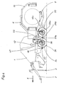
- FIG. 1 is a round baler 1, as z. B. is known from DE-PS 2443838, with a Drawbar 2 for attaching to a tractor, not shown, and with a support leg 3 for Shown the press shown.
- the round baler 1 is fixed on both sides with an im essentially horizontally extending main frame 4, which extends over an upward swiveling press housing part 5 extends backwards and a machine 6 for packaging the bale carries with film, consisting of an axis 7 lying transversely to the direction of travel X.
- the main frame 4 is made in two parts, a front one belonging to the round baler Frame part 12 is supported on a biaxial chassis 13.
- the chassis 13 has on everyone Press side two wheels 14 arranged one behind the other, one at a horizontal and transverse to Direction lying axis 15 pendulum-mounted double rocker 16 are arranged.
- the Wheels 14 are mounted on the double rocker 16 by means of stub axles.
- Each pendulum axis 15 is over an approximately vertically arranged support arm 17 is connected to the front frame part 12.
- About in the middle between the two joints of the support rocker arm 17 extends approximately in the direction of travel Hydraulic cylinder 18 on the support rocker 17, the other end on a downward beam 19 is articulated.
- the front frame part 12 ends on each side of the press in the rear direction a diagonally from the top to the bottom of the sloping flange part 20, the top, a fixed, after Catch hook 21 open at the top and a downwardly open one, pivotable about an axis 22, at the bottom Locking pawl 23 has, as can best be seen from FIG.
- the rear frame part 24 has a lower 25 at its front end on both sides of the press and upper cross bolts 26, which are fixed in a U-shaped counter flange 27 that is open in the direction of travel are arranged so that they can be brought into engagement with the catch hook 21 and the locking pawl 23 are.
- FIG 1 the locked state of the front 12 and rear frame part 24 is shown.
- the upper Cross bolt 26 lies in the upper catch hook 21.
- the locking pawl 23 engages over the lower one Cross bolt 25. Because the support arm 17 with its back against the locking pawl 23rd presses, a positive locking is guaranteed.
- the hydraulic cylinder 18 is located in extended position and the two-axle chassis 23 is in the rear position 28, so that the drawbar load on the drawbar 2 despite the saddled machine 6 for packing the bales with film does not assume negative values, as would be the case if the round baler had the axis arrangement according to solo operation.
- the round baler 1 is attached to a tractor, which is a support leg 3 high. Is a bale pressed and z. B. strapped with net, the rear Press housing part 5 swung up and the bale thrown onto a rust-like intermediate floor, which is inclined backwards so that the bale rolls onto the from the tilted wrapping table 8 and then wrapped in foil in the horizontal position of the changing table 8 and then through Tilting the changing table 8 backwards.
- the hydraulic cylinder 18 is retracted approximately half.
- the packaging machine 6 from FIG. 2 is connected to the tractor by means of an adapter part 31 connected, on the one hand the trailer bolts 32, 32a for the tractor three-point linkage 33 and on the other hand, not shown catch hooks and locking pawls according to FIGS. 1 and 2 for the Has cross bolts 25, 26 of the rear frame part 24, so that the packaging machine alone is ready for operation.
- each impeller 34, 35 is in Drawn arrangement suspended on a rocker 36, 36a, the ends around axes 37, 37a are pivotable and are supported at the other end on hydraulic cylinders 38, 38a which are located between rocker 36, 36a and frames 46, 46a are arranged. All four hydraulic cylinders 38, 38a are via oil lines 40, 41 connected with each other.
- the hydraulic system also has a hydraulic accumulator 42, two Shut-off valves 43, 44, a quick coupling 45 and a connecting line, not shown to tractor hydraulics.
- the main frame 46, 46a is made in two parts, the press-side flange 47 on both Sides of the round baler 1 has an upper and lower centering pin 48 with an annular groove 49, while the winding device-side flange 50 matches the centering pin 48 in the form of a keyhole Has recesses 51, as can best be seen from FIG. 6.
- the quick coupling 45 connects the oil lines 40 of the Round baler with 41 of the packaging machine 6.
- the shut-off valves 43, 44 are open and the hydraulic system is brought to a pressure value by means of the tractor hydraulics, which is a suspension the combination via the hydraulic accumulator 42 allowed.
- the wheels of the round baler can with Brakes, not shown, can be equipped for higher transport speeds.
- the combination is used to decouple the round baler 1 and the packaging machine 6 closed shut-off valve 44 raised by acting on the hydraulic cylinder 38, and the Packaging machine placed on support feet 52, which by slightly lowering the Round baler 1 takes place, so that the centering pin 48 down from the rectangular Recesses 51 slide, whereby the unlocking of both units 1, 6 takes place.
- the shut-off valve 43 is closed and the quick coupling 45 is separated.
- Both units 1, 6 are now open own wheels 34 and 35 can be used in solo mode. Since both the packaging machine 6 own Impellers 35 and the baler 1 do not require any axis shifts.
Landscapes
- Life Sciences & Earth Sciences (AREA)
- Environmental Sciences (AREA)
- Storage Of Harvested Produce (AREA)
- Auxiliary Devices For And Details Of Packaging Control (AREA)
- Photoreceptors In Electrophotography (AREA)
- Pharmaceuticals Containing Other Organic And Inorganic Compounds (AREA)
Description
- Fig. 1
- eine Seitenansicht einer erfindungsgemäßen Ballenpresse mit einer aufgesattelten Maschine zum Verpacken der Ballen mit Folie und nach hinten gefahrenem Achsaggregat,
- Fig. 2
- eine Ansicht nach Figur 1 bei abgehängter Maschine zum Verpacken der Ballen mit Folie und nach vorn gefahrenem Achsaggregat,
- Fig. 3
- in Seitenansicht die Maschine zum Verpacken der Ballen mit Folie mittels Adapter angehängt in die Dreipunkthydraulik eines Zugschleppers,
- Fig. 4
- eine Seitenansicht eines zweiten Ausführungsbeispieles einer erfindungsgemäßen Ballenpresse mit einer aufgesattelten Maschine zum Verpacken der Ballen mit Folie und Einzelradaufhängung hydraulisch gefedert,
- Fig. 5
- eine Ansicht nach Figur 4 bei abgehängter Maschine zum Verpacken der Ballen und
- Fig. 6
- die Verriegelung von Ballenpresse und Maschine zum Verpacken der Ballen mit Folie als Einzelheit in vergrößertem Maßstab mit Ansichten von vorn und hinten im abgehängten Zustand der Maschine zum Verpacken der Ballen.
Claims (9)
- Fahrbare Ballenpresse (1) für Stroh, Heu oder ähnliches Halmgut, welche mittels eines sich auf Laufrädern (14, 34, 35) abstützenden Hauptrahmens (4, 12, 24, 46, 46a) seitlich starr mit einer Maschine (6) zum Verpacken eines Ballens lösbar verbunden ist, wobei der Hauptrahmen (4, 12, 24, 46, 46a) auf beiden Seiten der Ballenpresse (1) eine Trennstelle mit Fang-, Führungs- und Verriegelungsvorrichtungen (21, 23, 48) sowie dazu passende Aufnahmen (25, 26, 51) zur Verriegelung jeweils eines vorderen (4, 12, 46) mit einem hinteren Hauptrahmenteil (24, 46a) aufweist, dadurch gekennzeichnet, dass die Verbindung zwischen vorderem (4, 12, 46) und hinterem Hauptrahmenteil (24, 46a) durch beidseitige Flanschverbindungen (20, 27, 47, 50) erfolgt, welche selbsttätig verriegelbar sind.
- Fahrbare Ballenpresse nach Anspruch 1, dadurch gekennzeichnet, dass die Ballenpresse (1) und/oder die Maschine (6) zum Verpacken eines Ballens mit Folie wenigstens eine Anhebevorrichtung (16, 17, 18, 36, 38) aufweisen / aufweist mittels der wenigstens ein Hauptrahmenteil (4, 12, 24, 46, 46a) im wesentlichen parallel zu seiner Horizontallage absenkbar bzw. anhebbar ist zum automatischen Entkuppeln bzw. Kuppeln von Ballenpresse (1) und Maschine (6) zum Verpacken des Ballens mit Folie.
- Fahrbare Ballenpresse nach Anspruch 2, dadurch gekennzeichnet, dass eine gesonderte Hubvorrichtung, z. B. ein hydraulisch betätigbarer Stützfuß, an geeigneter Stelle am Hauptrahmen oder am Pressenrahmen angebracht ist.
- Fahrbare Ballenpresse nach Anspruch 2, dadurch gekennzeichnet, dass wenigstens der vordere Hauptrahmen (4, 12) mittels einer Anhebevorrichtung (16, 17, 18) in vertikaler Richtung verstellbar ist und die Laufräder (14) bzw. deren Achsen in horizontaler Richtung verstellbar sind.
- Fahrbare Ballenpresse nach einem oder mehreren der Ansprüche 1 bis 4, dadurch gekennzeichnet, dass wenigstens eine Achse, ein Tandemachsaggregat (14, 15,16) oder jedes Laufrad (34, 35) einzeln im wesentlichen in Längsrichtung der Ballenpresse (1) durch Betätigung eines Stellorganes (18, 38, 38a) verschieb- oder verschwenkbar ist und bei Kombinationsbetrieb von Ballenpresse (1) und Maschine (6) zum Verpacken eines Ballens mit Folie nach hinten versetzt in Position (28) angeordnet ist relativ zu deren Position (30) beim Solobetrieb der Ballenpresse (1).
- Fahrbare Ballenpresse nach einem oder mehreren der vorhergehenden Ansprüche, dadurch gekennzeichnet, dass an jeder Seite der Ballenpresse (1) zwei Laufräder (14) angeordnet sind, die in Fahrtrichtung (X) hintereinander beidendig an Doppelschwingen (16) gelagert sind, die ihrerseits um quer zur Fahrtrichtung (X) liegende, mit den vorderen Hauptrahmenteilen (4, 12) oder mit dem Ballenpressenrahmen verbundenen Pendelachsen (15) schwingbar sind, wobei der Hauptrahmen (4) durch wenigstens eine Laufradpaarachse mittels eines Stellorganes anhebbar bzw. absenkbar ist.
- Fahrbare Ballenpresse nach einem oder mehreren der vorhergehenden Ansprüche, dadurch gekennzeichnet, dass beide Seiten der Pendelachse (15) bzw. die Doppelschwingen (16) durch vertikal oder nahezu vertikal angeordnete Tragschwingen (17) mit dem vorderen Hauptrahmenteil (4, 12) verbunden und durch ein Stellorgan (18) verschiebbar sind.
- Fahrbare Ballenpresse nach einem oder mehreren der vorhergehenden Ansprüche, dadurch gekennzeichnet, dass jedes Laufrad (34, 35) einzeln federnd und / oder hydraulisch beweglich an einer gezogenen Schwinge (36, 36a) aufgehängt ist, wobei ein vorderes Laufradpaar (34) der Ballenpresse (1) und ein hinteres Laufradpaar (35) der Maschine (6) zum Verpacken eines Ballens mit Folie zugeordnet ist mit dazwischengelegener Trennstelle des Hauptrahmens (46, 46a).
- Fahrbare Ballenpresse nach einem oder mehreren der vorhergehenden Ansprüche, dadurch gekennzeichnet, dass die Verschiebung bzw. die Verschwenkung der Laufräder (34, 35) oder der Pendelachse (15) bzw. des Tandemachsaggregates (14 bis 18) hydraulisch vom Schleppersitz erfolgt.
Applications Claiming Priority (2)
| Application Number | Priority Date | Filing Date | Title |
|---|---|---|---|
| DE19806460A DE19806460C1 (de) | 1998-02-17 | 1998-02-17 | Fahrbare Ballenpresse für Stroh, Heu oder ähnliches Halmgut |
| DE19806460 | 1998-02-17 |
Publications (3)
| Publication Number | Publication Date |
|---|---|
| EP0937384A2 EP0937384A2 (de) | 1999-08-25 |
| EP0937384A3 EP0937384A3 (de) | 2001-01-24 |
| EP0937384B1 true EP0937384B1 (de) | 2004-08-11 |
Family
ID=7857963
Family Applications (1)
| Application Number | Title | Priority Date | Filing Date |
|---|---|---|---|
| EP99102224A Expired - Lifetime EP0937384B1 (de) | 1998-02-17 | 1999-02-05 | Fahrbare Ballenpresse für Stroh, Heu oder ähnliches Halmgut |
Country Status (3)
| Country | Link |
|---|---|
| EP (1) | EP0937384B1 (de) |
| AT (1) | ATE272937T1 (de) |
| DE (2) | DE19806460C1 (de) |
Families Citing this family (8)
| Publication number | Priority date | Publication date | Assignee | Title |
|---|---|---|---|---|
| DE19950138C1 (de) * | 1999-10-18 | 2000-12-28 | Josef Fischer | Zusatzantriebsmodul für einen landwirtschaftlichen Schlepper |
| DE20005963U1 (de) | 2000-03-31 | 2000-06-21 | Kverneland Gottmadingen GmbH & Co. KG, 78244 Gottmadingen | Landwirtschaftliche Maschine |
| ES2462534T3 (es) * | 2001-03-22 | 2014-05-23 | Welmount Limited | Combinación de máquina embaladora/envolvedora de balas |
| EP1386532B1 (de) * | 2002-08-03 | 2006-11-15 | Welger Maschinenfabrik GmbH | Vorrichtung zum Umhüllen von Körpern |
| DE10240091A1 (de) * | 2002-08-28 | 2004-03-11 | Deere & Company, Moline | Wickelgerät |
| EP1393614A3 (de) | 2002-08-28 | 2009-06-03 | Deere & Company | Wickelgerät |
| DE102013108246A1 (de) * | 2013-08-01 | 2015-02-05 | Usines Claas France S.A.S. | Landwirtschaftliche Rundballenpresse |
| DE102013110626A1 (de) * | 2013-09-26 | 2015-03-26 | Usines Claas France S.A.S. | Rundballenpresse |
Family Cites Families (7)
| Publication number | Priority date | Publication date | Assignee | Title |
|---|---|---|---|---|
| DE7430874U (de) * | 1974-09-13 | 1977-05-26 | Welger Geb | Aufsammel-rollballenpresse |
| US4815266A (en) * | 1987-09-30 | 1989-03-28 | Hesston Corporation | Continuous round baler with accumulating trailer |
| FR2651959B1 (fr) * | 1989-09-20 | 1992-02-21 | Bugnot Ets | Dispositif groupeur de balles de fourrage cylindriques. |
| DE4120733C2 (de) * | 1991-06-22 | 1994-05-11 | Deere & Co | Fahrbare Ballenpresse |
| DE19613657A1 (de) * | 1996-04-04 | 1997-10-09 | Alfred Soeder | Wechselvorrichtung für an Fahrzeuge anbringbare Geräte |
| DE29711213U1 (de) * | 1997-06-27 | 1997-08-28 | Maschinenfabriken Bernard Krone Gmbh, 48480 Spelle | Vorrichtung zum kontinuierlichen und luftdichten Umhüllen von Körpern |
| DE19731520C2 (de) * | 1997-07-23 | 1999-08-05 | Bernd Biller | Vorrichtung zum Pressen und Umwickeln von Rundballen |
-
1998
- 1998-02-17 DE DE19806460A patent/DE19806460C1/de not_active Expired - Fee Related
-
1999
- 1999-02-05 DE DE59910155T patent/DE59910155D1/de not_active Expired - Lifetime
- 1999-02-05 EP EP99102224A patent/EP0937384B1/de not_active Expired - Lifetime
- 1999-02-05 AT AT99102224T patent/ATE272937T1/de not_active IP Right Cessation
Also Published As
| Publication number | Publication date |
|---|---|
| DE59910155D1 (de) | 2004-09-16 |
| ATE272937T1 (de) | 2004-08-15 |
| EP0937384A2 (de) | 1999-08-25 |
| EP0937384A3 (de) | 2001-01-24 |
| DE19806460C1 (de) | 1999-08-12 |
Similar Documents
| Publication | Publication Date | Title |
|---|---|---|
| DE2737053C3 (de) | Landwirtschaftlich nutzbares Arbeitsgerät | |
| EP0097347B1 (de) | Geräteträger | |
| EP0893053B1 (de) | Vorrichtung zum Pressen und Umwickeln von Rundballen | |
| EP0110056A2 (de) | Verfahren und Vorrichtung zum Transportieren und Lagern von Rundpressballen | |
| EP0784916B1 (de) | Fahrzeug zum Transport eines insbesondere fahrbaren Geräts | |
| DE3501062C2 (de) | ||
| DE19806460C1 (de) | Fahrbare Ballenpresse für Stroh, Heu oder ähnliches Halmgut | |
| DE3445222A1 (de) | Einrichtung an einem kraftfahrzeug zum aufnehmen und absetzen sowie zum kippen von behaeltern | |
| EP1186225A1 (de) | Kombination aus einer Presse, einem Wickelgerät und einem diese aufnehmenden Fahrgestell | |
| DE2411726B1 (de) | Stapelpresse für Feldfrüchte | |
| DE102007035796B4 (de) | Vorrichtung zur Arretierung eines Wagens zur Abstützung eines Erntevorsatzes bei einer Straßenfahrt an dem Erntevorsatz | |
| DE19928819A1 (de) | Ballenpresse | |
| DE202016100132U1 (de) | Rundballensammelvorrichtung und Rundballensammelfahrzeug mit einer derartigen Rundballensammelvorrichtung | |
| DE102004059038B4 (de) | Kombination aus einer Erntemaschine, einem Erntevorsatz und einem Wagen zur Abstützung des Erntevorsatzes | |
| DE19618263A1 (de) | Vorrichtung zum Schwenken der Tragarme von Vielkreisel-Heumaschinen | |
| DE3347220A1 (de) | Rundballenuebernahme-, lade- und transportfahrzeug | |
| DE9103150U1 (de) | Heuwerbungsmaschine | |
| DE3336313A1 (de) | Bodenstuetzgeraet fuer eine landmaschine | |
| DE3304166C2 (de) | Rundballenübernahme- und Transportfahrzeug | |
| DE1862681U (de) | Vorrichtung zum anheben und transportieren von lasten und maschinen. | |
| DE3713445C2 (de) | ||
| DE1630805C3 (de) | Aufsattelbarer Anhänger | |
| EP0763488B1 (de) | Müllsammelfahrzeug | |
| AT391787B (de) | Vorrichtung zum entnehmen von silage aus einem fahrsilo | |
| DE2621783A1 (de) | Verbindung zwischen einer zugmaschine und einem anhaenger |
Legal Events
| Date | Code | Title | Description |
|---|---|---|---|
| PUAI | Public reference made under article 153(3) epc to a published international application that has entered the european phase |
Free format text: ORIGINAL CODE: 0009012 |
|
| AK | Designated contracting states |
Kind code of ref document: A2 Designated state(s): AT CH DE FI FR GB IT LI NL |
|
| AX | Request for extension of the european patent |
Free format text: AL;LT;LV;MK;RO;SI |
|
| RAP3 | Party data changed (applicant data changed or rights of an application transferred) |
Owner name: LELY WELGER MASCHINENFABRIK GMBH |
|
| PUAL | Search report despatched |
Free format text: ORIGINAL CODE: 0009013 |
|
| AK | Designated contracting states |
Kind code of ref document: A3 Designated state(s): AT BE CH CY DE DK ES FI FR GB GR IE IT LI LU MC NL PT SE |
|
| AX | Request for extension of the european patent |
Free format text: AL;LT;LV;MK;RO;SI |
|
| 17P | Request for examination filed |
Effective date: 20010724 |
|
| AKX | Designation fees paid |
Free format text: AT CH DE FI FR GB IT LI NL |
|
| RAP1 | Party data changed (applicant data changed or rights of an application transferred) |
Owner name: LELY MASCHINENFABRIK GMBH |
|
| 17Q | First examination report despatched |
Effective date: 20020916 |
|
| GRAP | Despatch of communication of intention to grant a patent |
Free format text: ORIGINAL CODE: EPIDOSNIGR1 |
|
| RAP1 | Party data changed (applicant data changed or rights of an application transferred) |
Owner name: WELGER MASCHINENFABRIK GMBH |
|
| GRAS | Grant fee paid |
Free format text: ORIGINAL CODE: EPIDOSNIGR3 |
|
| GRAA | (expected) grant |
Free format text: ORIGINAL CODE: 0009210 |
|
| AK | Designated contracting states |
Kind code of ref document: B1 Designated state(s): AT CH DE FI FR GB IT LI NL |
|
| PG25 | Lapsed in a contracting state [announced via postgrant information from national office to epo] |
Ref country code: NL Free format text: LAPSE BECAUSE OF FAILURE TO SUBMIT A TRANSLATION OF THE DESCRIPTION OR TO PAY THE FEE WITHIN THE PRESCRIBED TIME-LIMIT Effective date: 20040811 Ref country code: IT Free format text: LAPSE BECAUSE OF FAILURE TO SUBMIT A TRANSLATION OF THE DESCRIPTION OR TO PAY THE FEE WITHIN THE PRESCRIBED TIME-LIMIT;WARNING: LAPSES OF ITALIAN PATENTS WITH EFFECTIVE DATE BEFORE 2007 MAY HAVE OCCURRED AT ANY TIME BEFORE 2007. THE CORRECT EFFECTIVE DATE MAY BE DIFFERENT FROM THE ONE RECORDED. Effective date: 20040811 Ref country code: FI Free format text: LAPSE BECAUSE OF FAILURE TO SUBMIT A TRANSLATION OF THE DESCRIPTION OR TO PAY THE FEE WITHIN THE PRESCRIBED TIME-LIMIT Effective date: 20040811 |
|
| REG | Reference to a national code |
Ref country code: GB Ref legal event code: FG4D Free format text: NOT ENGLISH |
|
| REG | Reference to a national code |
Ref country code: CH Ref legal event code: EP |
|
| REF | Corresponds to: |
Ref document number: 59910155 Country of ref document: DE Date of ref document: 20040916 Kind code of ref document: P |
|
| GBT | Gb: translation of ep patent filed (gb section 77(6)(a)/1977) |
Effective date: 20040906 |
|
| NLV1 | Nl: lapsed or annulled due to failure to fulfill the requirements of art. 29p and 29m of the patents act | ||
| PG25 | Lapsed in a contracting state [announced via postgrant information from national office to epo] |
Ref country code: AT Free format text: LAPSE BECAUSE OF NON-PAYMENT OF DUE FEES Effective date: 20050205 |
|
| PG25 | Lapsed in a contracting state [announced via postgrant information from national office to epo] |
Ref country code: LI Free format text: LAPSE BECAUSE OF NON-PAYMENT OF DUE FEES Effective date: 20050228 Ref country code: CH Free format text: LAPSE BECAUSE OF NON-PAYMENT OF DUE FEES Effective date: 20050228 |
|
| ET | Fr: translation filed | ||
| PLBE | No opposition filed within time limit |
Free format text: ORIGINAL CODE: 0009261 |
|
| STAA | Information on the status of an ep patent application or granted ep patent |
Free format text: STATUS: NO OPPOSITION FILED WITHIN TIME LIMIT |
|
| 26N | No opposition filed |
Effective date: 20050512 |
|
| REG | Reference to a national code |
Ref country code: CH Ref legal event code: PL |
|
| REG | Reference to a national code |
Ref country code: FR Ref legal event code: CD Owner name: LELY VERMEER MASCHINENFABRIK GMBH, DE Effective date: 20140507 |
|
| REG | Reference to a national code |
Ref country code: DE Ref legal event code: R081 Ref document number: 59910155 Country of ref document: DE Owner name: FORAGE COMPANY B.V., NL Free format text: FORMER OWNER: WELGER MASCHINENFABRIK GMBH, 38304 WOLFENBUETTEL, DE Effective date: 20140502 Ref country code: DE Ref legal event code: R081 Ref document number: 59910155 Country of ref document: DE Owner name: LELY MASCHINENFABRIK GMBH, DE Free format text: FORMER OWNER: WELGER MASCHINENFABRIK GMBH, 38304 WOLFENBUETTEL, DE Effective date: 20140502 Ref country code: DE Ref legal event code: R081 Ref document number: 59910155 Country of ref document: DE Owner name: LELY VERMEER MASCHINENFABRIK GMBH, DE Free format text: FORMER OWNER: WELGER MASCHINENFABRIK GMBH, 38304 WOLFENBUETTEL, DE Effective date: 20140502 |
|
| REG | Reference to a national code |
Ref country code: FR Ref legal event code: PLFP Year of fee payment: 17 |
|
| PGFP | Annual fee paid to national office [announced via postgrant information from national office to epo] |
Ref country code: GB Payment date: 20150226 Year of fee payment: 17 Ref country code: FR Payment date: 20150217 Year of fee payment: 17 |
|
| GBPC | Gb: european patent ceased through non-payment of renewal fee |
Effective date: 20160205 |
|
| REG | Reference to a national code |
Ref country code: FR Ref legal event code: ST Effective date: 20161028 |
|
| PG25 | Lapsed in a contracting state [announced via postgrant information from national office to epo] |
Ref country code: FR Free format text: LAPSE BECAUSE OF NON-PAYMENT OF DUE FEES Effective date: 20160229 Ref country code: GB Free format text: LAPSE BECAUSE OF NON-PAYMENT OF DUE FEES Effective date: 20160205 |
|
| REG | Reference to a national code |
Ref country code: DE Ref legal event code: R081 Ref document number: 59910155 Country of ref document: DE Owner name: FORAGE COMPANY B.V., NL Free format text: FORMER OWNER: LELY VERMEER MASCHINENFABRIK GMBH, 38304 WOLFENBUETTEL, DE Ref country code: DE Ref legal event code: R081 Ref document number: 59910155 Country of ref document: DE Owner name: LELY MASCHINENFABRIK GMBH, DE Free format text: FORMER OWNER: LELY VERMEER MASCHINENFABRIK GMBH, 38304 WOLFENBUETTEL, DE |
|
| PGFP | Annual fee paid to national office [announced via postgrant information from national office to epo] |
Ref country code: DE Payment date: 20170427 Year of fee payment: 19 |
|
| REG | Reference to a national code |
Ref country code: DE Ref legal event code: R081 Ref document number: 59910155 Country of ref document: DE Owner name: FORAGE COMPANY B.V., NL Free format text: FORMER OWNER: LELY MASCHINENFABRIK GMBH, 38304 WOLFENBUETTEL, DE |
|
| REG | Reference to a national code |
Ref country code: DE Ref legal event code: R119 Ref document number: 59910155 Country of ref document: DE |
|
| PG25 | Lapsed in a contracting state [announced via postgrant information from national office to epo] |
Ref country code: DE Free format text: LAPSE BECAUSE OF NON-PAYMENT OF DUE FEES Effective date: 20180901 |