EP0936050A2 - Extrusionskopf - Google Patents
Extrusionskopf Download PDFInfo
- Publication number
- EP0936050A2 EP0936050A2 EP99100596A EP99100596A EP0936050A2 EP 0936050 A2 EP0936050 A2 EP 0936050A2 EP 99100596 A EP99100596 A EP 99100596A EP 99100596 A EP99100596 A EP 99100596A EP 0936050 A2 EP0936050 A2 EP 0936050A2
- Authority
- EP
- European Patent Office
- Prior art keywords
- head part
- movable
- movable head
- head
- extrusion
- Prior art date
- Legal status (The legal status is an assumption and is not a legal conclusion. Google has not performed a legal analysis and makes no representation as to the accuracy of the status listed.)
- Granted
Links
Images


Classifications
-
- B—PERFORMING OPERATIONS; TRANSPORTING
- B29—WORKING OF PLASTICS; WORKING OF SUBSTANCES IN A PLASTIC STATE IN GENERAL
- B29C—SHAPING OR JOINING OF PLASTICS; SHAPING OF MATERIAL IN A PLASTIC STATE, NOT OTHERWISE PROVIDED FOR; AFTER-TREATMENT OF THE SHAPED PRODUCTS, e.g. REPAIRING
- B29C48/00—Extrusion moulding, i.e. expressing the moulding material through a die or nozzle which imparts the desired form; Apparatus therefor
- B29C48/25—Component parts, details or accessories; Auxiliary operations
- B29C48/36—Means for plasticising or homogenising the moulding material or forcing it through the nozzle or die
- B29C48/49—Means for plasticising or homogenising the moulding material or forcing it through the nozzle or die using two or more extruders to feed one die or nozzle
-
- B—PERFORMING OPERATIONS; TRANSPORTING
- B29—WORKING OF PLASTICS; WORKING OF SUBSTANCES IN A PLASTIC STATE IN GENERAL
- B29C—SHAPING OR JOINING OF PLASTICS; SHAPING OF MATERIAL IN A PLASTIC STATE, NOT OTHERWISE PROVIDED FOR; AFTER-TREATMENT OF THE SHAPED PRODUCTS, e.g. REPAIRING
- B29C48/00—Extrusion moulding, i.e. expressing the moulding material through a die or nozzle which imparts the desired form; Apparatus therefor
- B29C48/25—Component parts, details or accessories; Auxiliary operations
- B29C48/256—Exchangeable extruder parts
- B29C48/2562—Mounting or handling of the die
-
- B—PERFORMING OPERATIONS; TRANSPORTING
- B29—WORKING OF PLASTICS; WORKING OF SUBSTANCES IN A PLASTIC STATE IN GENERAL
- B29C—SHAPING OR JOINING OF PLASTICS; SHAPING OF MATERIAL IN A PLASTIC STATE, NOT OTHERWISE PROVIDED FOR; AFTER-TREATMENT OF THE SHAPED PRODUCTS, e.g. REPAIRING
- B29C48/00—Extrusion moulding, i.e. expressing the moulding material through a die or nozzle which imparts the desired form; Apparatus therefor
- B29C48/03—Extrusion moulding, i.e. expressing the moulding material through a die or nozzle which imparts the desired form; Apparatus therefor characterised by the shape of the extruded material at extrusion
- B29C48/07—Flat, e.g. panels
- B29C48/08—Flat, e.g. panels flexible, e.g. films
Definitions
- the invention is based on an extrusion head with a fixed one Headboard and one upper and lower movable headboard and possibly one movable intermediate part and - on each side - at least one Clamping device that moves the movable head parts to the fixed head part presses.
- Such an extrusion head is known from US 4,824,353, in which on fixed head section arranged clamping cylinders - each separately - the upper or press the lower movable head part against the fixed head part.
- the invention has for its object to the disadvantages described avoid and a safe even with extreme pressures and dimensions Ensure sealing.
- This object is achieved in that in addition to Clamping device for pressing the movable head parts against the stationary one Headboard a tensioning device is provided, the upper and the lower movable head part in the ready state in the direction of the other movable head section is tensioned.
- This allows the flat Partitions between the movable headboards and the fixed Headboard and the partitions between the movable headboards and the cassette or preform bar can be clamped together more effectively.
- the sealing effect is greater, the further the effective or force level Clamping device from an imaginary plane through the swivel axes of the movable headboards is removed.
- the additional Clamping device for the movable head parts formed by clamping cylinders, which are attached to one of the movable head parts, and with a gripping means are provided, which is a releasable connection to the other movable Allows headboard.
- the clamping cylinder are attached to the upper movable head part and with the gripping means grasp lower movable head part.
- a space-saving arrangement is achieved if the gripping means than around the own axis rotatable piston rod with hammer-shaped end piece is that for capturing a corresponding contact surface of the respective other movable head part is suitable.
- the extrusion head 1 has a fixed head part 2, an upper movable part Head part 3, a lower movable head part 4 and a movable intermediate head part 5 (hereinafter referred to only briefly as an intermediate part).
- the fixed head part 2 is mounted on a support 6 and with at least connected to an extruder, as for example in US 4,824,353 (especially Figs. 4 and 5).
- the upper movable head part 3 is about the horizontal axis 7 on the fixed headboard 2 articulated and can with the help of a motion cylinder 8 to rest on the fixed head part 2 (Fig. 1, 3) and by this away (Fig. 4) are pivoted.
- the lower movable head part 4 is about a lower horizontal one Axis 9 through a further movement cylinder 10 to the system the fixed head part 2 and pivoted away from it.
- the mobile Intermediate part 5 is also pivotable about the axis 9 and by one third movement cylinder 11 movable.
- the movable head parts 3 and 4 - the head part 4 with the interposition of the intermediate part 5 - are by in essentially horizontally arranged clamping cylinders 12, 13 to the fixed Pressed head part 2, as in the already mentioned US 4,824,353 is disclosed.
- a cassette 14 with a Profile bar 15 arranged in the common area of the head files 2 to 5 . These are by clamping wedges 16, 17 through Clamping cylinders 18, 19 are actuated in a corresponding recess of the extrusion head 1 pressed.
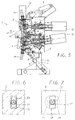
- the upper movable head part 3 has in its top lateral areas two further clamping cylinders 20. These tension cylinders have a telescopic piston rod 21 which can be extended downwards with a hammer-shaped end piece 22.
- the movable head parts 3, 4 point at their in the closed state mutually facing surfaces passage openings 23, 24 for the end pieces 22, which have a cross section corresponding to the end pieces. Viewed from the upper head part 3, it follows in the lower head part 4 the passage opening 24 has an undercut recess 25 with essentially circular cross-section, which is opposite the passage opening 24 forms a contact surface 26 for the end piece 22.
- the piston rod 21 of the clamping cylinder 20 is so far retracted that the end piece 22 within the movable head part 4th located. Even if the head parts 3 to 5 of the movement cylinders 8, 10, 11 are pressed against the fixed head part 2, there are Piston rods 21 still in the retracted position (Fig. 3).
- end pieces 22 are not that shown in FIGS. 6 and 7 Limited form. Rather, the end pieces 22 can also have the shape of the in Fig. 2 illustrated end piece 27 of the piston rod of the clamping cylinder 12. But there are also end pieces with more than two protrusions conceivable.
Landscapes
- Engineering & Computer Science (AREA)
- Mechanical Engineering (AREA)
- Extrusion Moulding Of Plastics Or The Like (AREA)
- Clamps And Clips (AREA)
- Extrusion Of Metal (AREA)
- Steps, Ramps, And Handrails (AREA)
Abstract
Description
- Fig. 1
- einen erfindungsgemäßen Extrusionskopf mit verriegelten Kopfteilen in einer teilweisen geschnittenen Seitenansicht,
- Fig. 2
- den Extrusionskopf gemäß Fig. 1 in der Stirnansicht,
- Fig. 3
- den Extrusionskopf mit noch geschlossenen, aber entriegelten Kopffeilen in einer teilweise geschnittenen Seitenansicht,
- Fig. 4
- der Extrusionskopf im geöffneten Zustand mit vollständig weg geschwenkten Kopfteilen in einer teilweise geschnittenen Seitenansicht,
- Fig. 5
- den Extrusionskopf in einer Computer-Seitenansicht",

- Fig. 6
- den Extrusionskopf in einem waagerechten auszugsweisen Querschnitt längs der Linie VI-VI in Fig. 1 und
- Fig. 7
- das untere bewegliche Kopfteil in einer gemäß der Linie VII-VII in Fig. 1 teilweise geschnittenen Draufsicht.
- 1
- Extrusionskopf
- 2
- feststehendes Kopfteil
- 3
- oberes bewegliches Kopfteil
- 4
- unteres bewegliches Kopfteil
- 5
- bewegliches Kopfzwischenteil, Zwischenteil
- 6
- Stütze
- 7
- waagerechte Achse für 3 an 2
- 8
- (erster) Bewegungszylinder für 3
- 9
- waagerechte Achse für 4 und 5 an 2
- 10
- weiterer Bewegungszylinder für 4
- 11
- dritter Bewegungszylinder für 5
- 12
- Spannzylinder
- 13
- Spannzylinder
- 14
- Kassette
- 15
- Profilleiste
- 16
- Klemmkeil
- 17
- Klemmkeil
- 18
- Klemmzylinder
- 19
- Klemmzylinder
- 20
- weitere Spannzylinder an 3
- 21
- telespopierbare Kolbenstange von 20
- 22
- hammerförmiges Endstück an 21
- 23
- Durchlaßöffnung in 3 für 22
- 24
- Durchlaßöffnung in 4 für 22
- 25
- hinterschnittene Ausnehmung in 4
- 26
- Anlagefläche in 4 für 22
- 27
- Endstück
Claims (5)
- Extrusionskopf (1) mit einem feststehenden Kopfteil (2) und je einem oberen und unteren beweglichen Kopfteil (3 bzw. 4) und ggf. einem beweglichen Zwischenteil (5) sowie - auf jeder Seite - mindestens einer Spanneinrichtung (12, 13), die die beweglichen Kopfteile (3, 4, 5) an das feststehende Kopfteil (2) preßt,
dadurch gekennzeichnet,
daß zusätzlich zu der Spanneinrichtung (12, 13) zum Anpressen der beweglichen Kopfteile (3, 4, 5) an das feststehende Kopfteil (2) eine Spanneinrichtung (20) vorgesehen ist, die das obere und das untere bewegliche Kopfteil (3, 4) im betriebsbereiten Zustand jeweils in Richtung auf das andere bewegliche Kopfteil (4 bzw. 3) spannt. - Extrusionskopf nach Anspruch 1, dadurch gekennzeichnet, daß die zusätzliche Spanneinrichtung (20) für die beweglichen Kopfteile (3, 4) durch Spannzylinder (20) gebildet ist, die an einem der beweglichen Kopfteile (3) befestigt und mit einem Greifmittel versehen sind, das eine lösbare Verbindung zu dem jeweils anderen beweglichen Kopfteil (4) ermöglicht.
- Extrusionskopf nach Anspruch 1 oder 2, dadurch gekennzeichnet, daß die Spannzylinder (20) an dem oberen beweglichen Kopfteil (3) befestigt sind und mit dem Greifmittel das untere beweglichen Kopfteil (4) erfassen.
- Extrusionskopf nach Anspruch 2 oder 3, dadurch gekennzeichnet, daß das Greifmittel als um die eigene Achse drehbare Kolbenstange (21) mit hammerförmigem Endstück (22) ausgebildet ist, das zum Erfassen einer entsprechenden Anlagefläche (26) des jeweils anderen beweglichen Kopfteils (4) geeignet ist.
- Extrusionskopf nach einem der Ansprüche 2 bis 4, dadurch gekennzeichnet, daß die Spannzylinder (20) in den seitlichen Bereichen des betreffenden beweglichen Kopfteils (3) angeordnet sind.
Applications Claiming Priority (2)
| Application Number | Priority Date | Filing Date | Title |
|---|---|---|---|
| DE19803269A DE19803269A1 (de) | 1998-01-29 | 1998-01-29 | Extrusionskopf |
| DE19803269 | 1998-01-29 |
Publications (3)
| Publication Number | Publication Date |
|---|---|
| EP0936050A2 true EP0936050A2 (de) | 1999-08-18 |
| EP0936050A3 EP0936050A3 (de) | 2001-01-24 |
| EP0936050B1 EP0936050B1 (de) | 2004-06-02 |
Family
ID=7855923
Family Applications (1)
| Application Number | Title | Priority Date | Filing Date |
|---|---|---|---|
| EP99100596A Expired - Lifetime EP0936050B1 (de) | 1998-01-29 | 1999-01-14 | Extrusionskopf |
Country Status (5)
| Country | Link |
|---|---|
| US (1) | US6273703B1 (de) |
| EP (1) | EP0936050B1 (de) |
| JP (1) | JPH11262946A (de) |
| DE (2) | DE19803269A1 (de) |
| ES (1) | ES2217622T3 (de) |
Cited By (2)
| Publication number | Priority date | Publication date | Assignee | Title |
|---|---|---|---|---|
| GB2381235A (en) * | 2001-08-14 | 2003-04-30 | Greiner Extrusionstechnik Gmbh | Retaining device for an extrusion die |
| EP1306189A3 (de) * | 2001-10-25 | 2005-01-19 | Extrusion Dies Industries, LLC | Schnell auswechselbare / demontierbare Extrusionsdüse |
Families Citing this family (9)
| Publication number | Priority date | Publication date | Assignee | Title |
|---|---|---|---|---|
| EP1481785A1 (de) * | 2003-05-28 | 2004-12-01 | Coperion Werner & Pfleiderer GmbH & Co. KG | Anlage zum Aufbereiten von Stoffen |
| JP3837433B2 (ja) * | 2004-07-20 | 2006-10-25 | 横浜ゴム株式会社 | 押出しヘッド |
| DE102007030679B3 (de) * | 2007-07-02 | 2009-01-08 | Troester Gmbh & Co. Kg | Spritzkopf |
| DE102009048980A1 (de) * | 2009-10-09 | 2011-04-14 | Troester Gmbh & Co. Kg | Spritzkopf sowie eine mit einem solchen Spritzkopf ausgestattete Extrusionsvorrichtung |
| KR101042925B1 (ko) | 2010-02-23 | 2011-06-20 | 주식회사 우성기공 | 가동헤드 타이어 압출기 |
| JP5853022B2 (ja) * | 2010-08-23 | 2016-02-09 | ハールブルク・フロイデンベルガーマシーネンバウ ゲーエムベーハー | 押し出し成形装置 |
| DE102014117068B4 (de) | 2014-11-21 | 2020-04-23 | KraussMaffei Extrusion GmbH | Mehrfach-Strangpresskopf sowie Laufprofil-Herstellvorrichtung zum Herstellen von Laufprofilen von Fahrzeugreifen |
| CN107310127B (zh) * | 2017-08-08 | 2023-05-05 | 中国化学工业桂林工程有限公司 | 一种快开式橡胶挤出机头 |
| JP6518390B1 (ja) * | 2019-01-11 | 2019-05-22 | 中田エンヂニアリング株式会社 | 多層押出し装置のヘッド |
Citations (3)
| Publication number | Priority date | Publication date | Assignee | Title |
|---|---|---|---|---|
| US4372736A (en) * | 1981-02-17 | 1983-02-08 | Usm Corporation | Adjustable roller head extrusion die |
| US4824353A (en) * | 1986-11-27 | 1989-04-25 | Fried. Krupp Gesellschaft Mit Beschrankter Haftung | Extruder head |
| US5472332A (en) * | 1992-10-20 | 1995-12-05 | Paul Troester Maschinenfabrik | Extruder head for an extruder |
Family Cites Families (3)
| Publication number | Priority date | Publication date | Assignee | Title |
|---|---|---|---|---|
| DE2937204C2 (de) * | 1979-09-14 | 1982-09-02 | Werner & Pfleiderer, 7000 Stuttgart | Extrudermaschine mit Breitspritzkopf und zugeordnetem Kalander |
| DE19517246A1 (de) * | 1995-05-15 | 1996-11-21 | Troester Maschf Paul | Spritzkopf für eine Extrusionsanlage der Kautschuk oder Kunststoff verarbeitenden Industrie |
| DE19628608A1 (de) * | 1996-07-16 | 1998-01-22 | Krupp Kunststofftechnik Gmbh | Extrusionskopf mit Schließzylindern |
-
1998
- 1998-01-29 DE DE19803269A patent/DE19803269A1/de not_active Withdrawn
-
1999
- 1999-01-14 ES ES99100596T patent/ES2217622T3/es not_active Expired - Lifetime
- 1999-01-14 EP EP99100596A patent/EP0936050B1/de not_active Expired - Lifetime
- 1999-01-14 DE DE59909620T patent/DE59909620D1/de not_active Expired - Lifetime
- 1999-01-26 US US09/237,417 patent/US6273703B1/en not_active Expired - Lifetime
- 1999-01-28 JP JP11020160A patent/JPH11262946A/ja not_active Withdrawn
Patent Citations (3)
| Publication number | Priority date | Publication date | Assignee | Title |
|---|---|---|---|---|
| US4372736A (en) * | 1981-02-17 | 1983-02-08 | Usm Corporation | Adjustable roller head extrusion die |
| US4824353A (en) * | 1986-11-27 | 1989-04-25 | Fried. Krupp Gesellschaft Mit Beschrankter Haftung | Extruder head |
| US5472332A (en) * | 1992-10-20 | 1995-12-05 | Paul Troester Maschinenfabrik | Extruder head for an extruder |
Cited By (5)
| Publication number | Priority date | Publication date | Assignee | Title |
|---|---|---|---|---|
| GB2381235A (en) * | 2001-08-14 | 2003-04-30 | Greiner Extrusionstechnik Gmbh | Retaining device for an extrusion die |
| GB2381235B (en) * | 2001-08-14 | 2005-02-23 | Greiner Extrusionstechnik Gmbh | Retaining device for an extrusion die |
| AT413270B (de) * | 2001-08-14 | 2006-01-15 | Greiner Extrusionstechnik Gmbh | Haltevorrichtung für eine extrusionsdüse |
| DE10235151B4 (de) * | 2001-08-14 | 2012-10-04 | Greiner Extrusionstechnik Gmbh | Haltevorrichtung für eine Extrusionsdüse |
| EP1306189A3 (de) * | 2001-10-25 | 2005-01-19 | Extrusion Dies Industries, LLC | Schnell auswechselbare / demontierbare Extrusionsdüse |
Also Published As
| Publication number | Publication date |
|---|---|
| ES2217622T3 (es) | 2004-11-01 |
| DE59909620D1 (de) | 2004-07-08 |
| US6273703B1 (en) | 2001-08-14 |
| EP0936050B1 (de) | 2004-06-02 |
| DE19803269A1 (de) | 1999-08-05 |
| JPH11262946A (ja) | 1999-09-28 |
| EP0936050A3 (de) | 2001-01-24 |
Similar Documents
| Publication | Publication Date | Title |
|---|---|---|
| EP0628362B1 (de) | Presswerkzeug | |
| DE3423283C2 (de) | ||
| EP2315877B1 (de) | Schweissaggregat zum verschweissen von schienen eines gleises | |
| EP0936050B1 (de) | Extrusionskopf | |
| DD275208A5 (de) | Extrusionskopf | |
| DE4115224C2 (de) | Spannvorrichtung für Oberwerkzeuge an Abkantpressen | |
| EP0743162B1 (de) | Spritzkopf für eine Extrusionsanlage der Kautschuk oder Kunststoff verarbeitenden Industrie | |
| DE2201631B2 (de) | Strangpreßkopf zum Herstellen von Flachprofilen aus zwei verschiedenartigen Mischungen | |
| DE6807476U (de) | Sicherheitsvorrichtung fuer hub-greifzangen | |
| DE4436715A1 (de) | Hub-Dreh-Vorrichtung zur Aufnahme eines Kraftfahrzeuges | |
| DE19733536C2 (de) | Biegevorrichtung mit einem Niederhalter für Hohlprofile | |
| DE2512823A1 (de) | Plattenfilterpresse mit einstellbarer endplatte | |
| EP0819511B1 (de) | Extrusionskopf mit Schliesszylindern | |
| CH679918A5 (de) | ||
| DE2620522C3 (de) | Klemmvorrichtung für einen Schalungszuganker | |
| DE19955289C2 (de) | Buchsenziehvorrichtung | |
| EP0596279B1 (de) | Spritzkopf für eine Extrusionsanlage der Kautschuk oder Kunststoff verarbeitenden Industrie | |
| DE4323728A1 (de) | Schweißvorrichtung für rechteckige Rahmen, insbesondere Fensterrahmen | |
| CH662292A5 (de) | Vorrichtung zum herstellen von metallbaendern. | |
| DE2540644A1 (de) | Laengenveraenderbare stange, insbesondere erdungsstange oder betaetigungsstange fuer elektrotechnische einrichtungen | |
| DE3939458C2 (de) | Gerät zum Herausziehen von Befestigungsmitteln | |
| DE2853748C2 (de) | Vorrichtung zum Verschließen der Austrittsöffnung einer Elektrodenpresse | |
| DE10106560C2 (de) | Verleimpresse mit mindestens einem Niederhalter | |
| DE3427387C2 (de) | ||
| DE2108205C3 (de) | Schlagwerkzeug |
Legal Events
| Date | Code | Title | Description |
|---|---|---|---|
| PUAI | Public reference made under article 153(3) epc to a published international application that has entered the european phase |
Free format text: ORIGINAL CODE: 0009012 |
|
| AK | Designated contracting states |
Kind code of ref document: A2 Designated state(s): DE ES FR GB IT |
|
| AX | Request for extension of the european patent |
Free format text: AL;LT;LV;MK;RO;SI |
|
| PUAL | Search report despatched |
Free format text: ORIGINAL CODE: 0009013 |
|
| AK | Designated contracting states |
Kind code of ref document: A3 Designated state(s): AT BE CH CY DE DK ES FI FR GB GR IE IT LI LU MC NL PT SE |
|
| AX | Request for extension of the european patent |
Free format text: AL;LT;LV;MK;RO;SI |
|
| 17P | Request for examination filed |
Effective date: 20010724 |
|
| AKX | Designation fees paid |
Free format text: DE ES FR GB IT |
|
| 17Q | First examination report despatched |
Effective date: 20030224 |
|
| RAP1 | Party data changed (applicant data changed or rights of an application transferred) |
Owner name: THYSSENKRUPP AG |
|
| GRAP | Despatch of communication of intention to grant a patent |
Free format text: ORIGINAL CODE: EPIDOSNIGR1 |
|
| RAP1 | Party data changed (applicant data changed or rights of an application transferred) |
Owner name: THYSSENKRUPP ELASTOMERTECHNIK GMBH |
|
| GRAS | Grant fee paid |
Free format text: ORIGINAL CODE: EPIDOSNIGR3 |
|
| GRAA | (expected) grant |
Free format text: ORIGINAL CODE: 0009210 |
|
| AK | Designated contracting states |
Kind code of ref document: B1 Designated state(s): DE ES FR GB IT |
|
| REG | Reference to a national code |
Ref country code: GB Ref legal event code: FG4D Free format text: NOT ENGLISH |
|
| GBT | Gb: translation of ep patent filed (gb section 77(6)(a)/1977) |
Effective date: 20040602 |
|
| REF | Corresponds to: |
Ref document number: 59909620 Country of ref document: DE Date of ref document: 20040708 Kind code of ref document: P |
|
| REG | Reference to a national code |
Ref country code: ES Ref legal event code: FG2A Ref document number: 2217622 Country of ref document: ES Kind code of ref document: T3 |
|
| ET | Fr: translation filed | ||
| PGFP | Annual fee paid to national office [announced via postgrant information from national office to epo] |
Ref country code: GB Payment date: 20050104 Year of fee payment: 7 |
|
| PLBE | No opposition filed within time limit |
Free format text: ORIGINAL CODE: 0009261 |
|
| STAA | Information on the status of an ep patent application or granted ep patent |
Free format text: STATUS: NO OPPOSITION FILED WITHIN TIME LIMIT |
|
| 26N | No opposition filed |
Effective date: 20050303 |
|
| PG25 | Lapsed in a contracting state [announced via postgrant information from national office to epo] |
Ref country code: GB Free format text: LAPSE BECAUSE OF NON-PAYMENT OF DUE FEES Effective date: 20060114 |
|
| GBPC | Gb: european patent ceased through non-payment of renewal fee |
Effective date: 20060114 |
|
| PGFP | Annual fee paid to national office [announced via postgrant information from national office to epo] |
Ref country code: ES Payment date: 20120126 Year of fee payment: 14 |
|
| REG | Reference to a national code |
Ref country code: ES Ref legal event code: FD2A Effective date: 20140324 |
|
| PGFP | Annual fee paid to national office [announced via postgrant information from national office to epo] |
Ref country code: DE Payment date: 20140122 Year of fee payment: 16 |
|
| PG25 | Lapsed in a contracting state [announced via postgrant information from national office to epo] |
Ref country code: ES Free format text: LAPSE BECAUSE OF NON-PAYMENT OF DUE FEES Effective date: 20130115 |
|
| PGFP | Annual fee paid to national office [announced via postgrant information from national office to epo] |
Ref country code: FR Payment date: 20140123 Year of fee payment: 16 Ref country code: IT Payment date: 20140131 Year of fee payment: 16 |
|
| REG | Reference to a national code |
Ref country code: DE Ref legal event code: R119 Ref document number: 59909620 Country of ref document: DE |
|
| PG25 | Lapsed in a contracting state [announced via postgrant information from national office to epo] |
Ref country code: DE Free format text: LAPSE BECAUSE OF NON-PAYMENT OF DUE FEES Effective date: 20150801 |
|
| REG | Reference to a national code |
Ref country code: FR Ref legal event code: ST Effective date: 20150930 |
|
| PG25 | Lapsed in a contracting state [announced via postgrant information from national office to epo] |
Ref country code: FR Free format text: LAPSE BECAUSE OF NON-PAYMENT OF DUE FEES Effective date: 20150202 |
|
| PG25 | Lapsed in a contracting state [announced via postgrant information from national office to epo] |
Ref country code: IT Free format text: LAPSE BECAUSE OF NON-PAYMENT OF DUE FEES Effective date: 20150114 |