EP0935943B1 - Staubsauger - Google Patents
Staubsauger Download PDFInfo
- Publication number
- EP0935943B1 EP0935943B1 EP19990102552 EP99102552A EP0935943B1 EP 0935943 B1 EP0935943 B1 EP 0935943B1 EP 19990102552 EP19990102552 EP 19990102552 EP 99102552 A EP99102552 A EP 99102552A EP 0935943 B1 EP0935943 B1 EP 0935943B1
- Authority
- EP
- European Patent Office
- Prior art keywords
- vacuum cleaner
- switching device
- channel
- atmospheric pressure
- sub
- Prior art date
- Legal status (The legal status is an assumption and is not a legal conclusion. Google has not performed a legal analysis and makes no representation as to the accuracy of the status listed.)
- Expired - Lifetime
Links
- 239000000428 dust Substances 0.000 claims description 15
- 239000004065 semiconductor Substances 0.000 claims description 8
- 239000004020 conductor Substances 0.000 claims description 2
- 239000002775 capsule Substances 0.000 description 5
- 238000005192 partition Methods 0.000 description 3
- 238000001816 cooling Methods 0.000 description 2
- 239000012528 membrane Substances 0.000 description 2
- 230000013011 mating Effects 0.000 description 1
Images

Classifications
-
- A—HUMAN NECESSITIES
- A47—FURNITURE; DOMESTIC ARTICLES OR APPLIANCES; COFFEE MILLS; SPICE MILLS; SUCTION CLEANERS IN GENERAL
- A47L—DOMESTIC WASHING OR CLEANING; SUCTION CLEANERS IN GENERAL
- A47L9/00—Details or accessories of suction cleaners, e.g. mechanical means for controlling the suction or for effecting pulsating action; Storing devices specially adapted to suction cleaners or parts thereof; Carrying-vehicles specially adapted for suction cleaners
- A47L9/10—Filters; Dust separators; Dust removal; Automatic exchange of filters
- A47L9/19—Means for monitoring filtering operation
Definitions
- the invention relates to a vacuum cleaner, with a certain state in the vacuum cleaner indicating device in which an electrical display element is switchable by means of an existing between the ambient pressure and the pressure prevailing in the dust chamber of the vacuum cleaner vacuum pressure switchable electrical switching device.
- Such a vacuum cleaner is known from DE-B-27 12 201.
- an electrical switching device is provided, in which a between the ambient pressure and the prevailing in the dust chamber vacuum pressure difference membrane is coupled to a switch pin. As a result of a caused by the pressure difference movement of the membrane of the switching pin comes into contact with a mating contact and thereby closes the circuit of an indicator light.
- a separate electrical connection of the switching device is required.
- the switching device is arranged directly on a printed circuit board installed in the vacuum cleaner housing.
- the invention is the task zuofficerand to make such an electronic building unit, which is more compact, works zweriner and can be mounted in a simple manner.
- a rotational speed control of the fan motor of the vacuum cleaner serving semiconductor switching element is arranged projecting into the channel in alignment with the connectable to the channel vacuum side of the switching device to the circuit board.
- a cooling of the semiconductor switching element without pressure losses in the dust chamber is achieved in that at different circumferential locations of the channel wall at least two offset with respect to their height levels perforations are arranged such that they are on their side adjacent to the dust chamber in the range of different flow velocities of the suction air stream.
- the housing of a vacuum cleaner has a dust chamber 2, a blower unit 3 accommodating a blower chamber 4 and a cable drum 5 containing auxiliary chamber 6.
- the dust chamber 2 is delimited by a partition wall 7 with respect to the fan chamber 4 and the secondary chamber 6. In the corner region where the partition wall 7 and the intermediate wall 8 abut each other, a channel 9 of rectangular cross-section is formed.
- a printed circuit board 13 is inserted on the one hand in a U-shaped guide rail and on the other hand in a slot of a channel wall 12.
- a formed in the manner of a valve electrical switching device 14 is disposed in the region of the channel 9 on the circuit board 13 that the Switching device 14 engages with a corresponding in its cross-sectional shape of the cross-sectional shape of the channel 9 conical connecting edge 15 in the channel 9. Due to the cone-like design of the terminal edge 15 a good seal of the channel 9 is achieved.
- the channel 9 is connected by a first opening 16, which is arranged in terms of height in the region of a channel 9 on its one side closing bottom wall 17, pressure moderately connected to the dust chamber 2.
- the channel 9 has a second opening 19. This second opening 19 is offset from the first opening 16 in height.
- the passage opening 18 because of its proximity to the passage opening 18, it is in a range of higher flow velocity of the suction air flow. In the region of the first opening 16, the flow velocity of the suction air flow is substantially lower.
- the connected to the channel 9 by means of its terminal edge 15 switching device 14 includes in its housing capsule 20, a piston 21 which is held by a spring 22 sealingly against an inlet port 23 of the housing capsule 20. On the inlet opening 23 opposite side is surrounded by the terminal edge 15 connecting opening 24 is provided.
- electrical contact elements are further arranged between which a conductive connection can be produced by a arranged on the piston 21 switching bridge. On the other hand, the contact elements are connected to strip conductors, which in turn make the contact connection to a display element.
- a semiconductor switching element 25 is still arranged on the circuit board 13.
- the semiconductor switching element 25 immersed in the channel 9, which is then sealed by the terminal edge 15 of the housing capsule 20 on this page.
- a negative pressure is generated in the region of this second opening 19.
- 16 air from the dust chamber 2 flows into the channel 9 via the first opening and flows out again via the second opening 19.
- this air flows past the semiconductor switching element 25, or to cooling flags connected thereto and cools the semiconductor switching element 25 accordingly.
- the pressure connection of the electrical switching device 14 is used to the dust chamber 2 for pressure-sensitive delimitation of the semiconductor switching element 25 against leading to Saug chequeshneen outside pressure.
Landscapes
- Engineering & Computer Science (AREA)
- Mechanical Engineering (AREA)
- Electric Vacuum Cleaner (AREA)
Description
- Die Erfindung betrifft einen Staubsauger, mit einer einen bestimmten Zustand im Staubsauger anzeigenden Vorrichtung, bei der mittels einer durch den zwischen dem Umgebungsdruck und dem im Staubraum des Staubsaugers herrschenden Unterdruck bestehenden Druckunterschied betätigbaren elektrischen Schaltvorrichtung ein elektrisches Anzeigeelement schaltbar ist.
- Ein solcher Staubsauger ist durch die DE-B-27 12 201 bekannt. Bei diesem bekannten Staubsauger ist eine elektrische Schaltvorrichtung vorgesehen, bei der eine dem zwischen dem Umgebungsdruck und dem im Staubraum herrschenden Unterdruck bestehenden Druckdifferenz ausgesetzte Membran mit einem Schaltstift gekoppelt ist. Infolge einer durch die Druckdifferenz hervorgerufenen Bewegung der Membran gelangt der Schaltstift mit einem Gegenkontakt in Berührung und schließt dadurch den Stromkreis einer Anzeigeleuchte. Bei diesem bekannten Staubsauger ist ein gesondertes elektrisches Anschließen der Schaltvorrichtung erforderlich.
- Im von US-A-4 514 874 bekannten Staubsauger ist dagegen die Schaltvorrichtung direkt auf einer im Staubsaugergehäuse eingebauten Leiterplatte angeordnet.
- Der Erfindung liegt die aufgabezugrande, eine solche elektronische Baureinheit zu gestalten, die kompakter ist, zwerlässiger arbeitet und in einfacher weise montiert werden Kann.
- Die Lösung der gestellten Aufgabe gelingt nach der Erfindung durch die im charakterisierenden Teil des Anspruchs 1 enthaltenen Merkmale.
- Für die druckmäßige Verbindung der Schaltvorrichtung mit dem Staubraum werden dadurch keine gesonderten Anschlußelemente benötigt, daß die Schaltvorrichtung mit ihrer Unterdruckseite an einen im Staubsaugergehäuse ausgebildeten, durch den im Staubraum des Staubsaugers herrschenden Unterdruck beaufschlagten, röhrenförmigen Kanal abgedichtet angeschlossen ist.
- Nach der Erfindung ist fluchtend zu der an den Kanal anschließbaren Unterdruckseite der Schaltvorrichtung an der Leiterplatte ein der Drehzahlsteuerung des Gebläsemotors des Staubsaugers dienendes Halbleiterschaltelement in den Kanal ragend angeordnet.
- Eine Kühlung des Halbleiterschaltelementes ohne Druckverluste im Staubraum wird dadurch erzielt, daß an unterschiedlichen Umfangsstellen der Kanalwand mindestens zwei hinsichtlich ihres Höhenniveaus gegeneinander versetzten Durchbrechungen derart angeordnet sind, daß diese auf ihrer dem Staubraum benachbarten Seite im Bereich unterschiedlicher Strömungsgeschwindigkeiten des Saugluftstromes liegen.
- Anhand eines in der Zeichnung dargestellten Ausführungsbeispieles wird die Erfindung nachfolgend noch näher erläutert.
- Es zeigt:
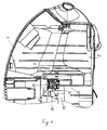
- FIG 1
- einen Staubsauger im Teillängsschnitt
- FIG 2
- in vergrößerter Darstellung die Anordnung einer Schaltvorrichtung im Staubsauger
- FIG 3
- eine Teilansicht entlang der Linie III-III in Fig. 1
- Das Gehäuse eines Staubsaugers weist einen Staubraum 2, einen ein Gebläseaggregat 3 aufnehmenden Gebläseraum 4 und eine eine Kabeltrommel 5 enthaltende Nebenkammer 6 auf. Der Staubraum 2 ist durch eine Trennwand 7 gegenüber dem Gebläseraum 4 und der Nebenkammer 6 abgegrenzt. In dem Eckbereich, wo die Trennwand 7 und die Zwischenwand 8 aneinanderstoßen ist ein im Querschnitt eckiger Kanal 9 ausgebildet.
- An der Zwischenwand 8 ist eine einerseits in eine U-förmige Führungsleiste und andererseits in einen Schlitz der einen Kanalwand 12 eingesetzte Leiterplatte 13 angeordnet. Eine nach Art eines Ventils ausgebildete elektrische Schaltvorrichtung 14 ist im Bereich des Kanals 9 so an der Leiterplatte 13 angeordnet, daß die Schaltvorrichtung 14 mit einem in seiner Querschnittsform der Querschnittsform des Kanals 9 entsprechenden konusartigen Anschlußrand 15 in den Kanal 9 eingreift. Durch die konusartige Ausbildung des Anschlußrandes 15 wird eine gute Abdichtung des Kanals 9 erreicht.
- Der Kanal 9 ist durch eine erste Durchbrechung 16, welche höhenmäßig im Bereich einer den Kanal 9 auf seiner einen Seite verschließenden Bodenwand 17 angeordnet ist, druckmäßig mit dem Staubraum 2 verbunden. In einem zu der in der Trennwand 7 für den Anschluß des Gebläseaggregates 3 vorgesehenen Durchlaßöffnung 18 hin gerichteten Bereich weist der Kanal 9 eine zweite Durchbrechung 19 auf. Diese zweite Durchbrechung 19 ist gegenüber der ersten Durchbrechung 16 in der Höhe versetzt. Außerdem liegt sie wegen ihrer Nachbarschaft zu der Durchlaßöffnung 18 in einem Bereich höherer Strömungsgeschwindigkeit des Saugluftstromes. Im Bereich der ersten Durchbrechung 16 ist die Strömungsgeschwindigkeit des Saugluftstromes wesentlich geringer.
- Die an den Kanal 9 mittels ihres Anschlußrandes 15 angeschlossene Schaltvorrichtung 14 enthält in ihrer Gehäusekapsel 20 einen Kolben 21, der durch eine Feder 22 dichtend gegen eine Einlaßöffnung 23 der Gehäusekapsel 20 gehalten wird. Auf der der Einlaßöffnung 23 gegenüberliegenden Seite ist eine von dem Anschlußrand 15 umgebene Anschlußöffnung 24 vorgesehen. Am Boden der Gehäusekapsel 20 sind ferner elektrische Kontaktelemente angeordnet, zwischen denen durch eine am Kolben 21 angeordnete Schaltbrücke eine leitende Verbindung herstellbar ist. Die Kontaktelemente sind andererseits mit Leiterbahnen verbunden, durch die wiederum die Kontaktverbindung zu einem Anzeigeelment besteht.
- Über die Einlaßöffnung 23 wirkt der Umgebungsdruck und über die Anschlußöffnung 24 der in dem Staubraum 2 herrschende Unterdruck auf den Kolben 21 ein. Sobald die durch den Druckunterschied auf den Kolben 21 wirkende Druckkraft größer als die Kraft der Feder 22 ist, wird der Kolben 21 in der Gehäusekapsel 20 zu der Anschlußöffnung 24 hin bewegt. Mittels der mit dem Kolben 21 verbundenen Schaltbrücken wird eine leitende Verbindung hergestellt, d.h. der Stromkreis eines Anzeigeelementes wird geschlossen und das Anzeigeelement gibt eine entsprechende Meldung. Da der Querschnitt der Einlaßöffnung 23 kleiner als die Kolbenfläche ist, erfolgt im Augenblick des Ansprechens des Kolbens 21 eine Druckverstärkung, wodurch der Kolben 21 sicher zu der Anschlußöffnung 24 bewegt und auch ein Schwingen des Kolbens 21 weitgehend ausgeschlossen wird. Es ergibt sich daher ein prellfreies Schalten der Schaltvorrichtung 14.
- Unterhalb des Anschlußrandes 15 der elektrischen Schaltvorrichtung 14 ist an der Leiterplatte 13 noch ein Halbleiterschaltelement 25 angeordnet. Beim Anstecken der Leiterplatte 13 an der Zwischenwand 8 taucht das Halbleiterschaltelement 25 in den Kanal 9, der dann durch den Anschlußrand 15 der Gehäusekapsel 20 auf dieser Seite dicht verschlossen wird. Durch die an der zweiten Durchbrechung 19 vorbeiströmende Saugluft wird im Bereich dieser zweiten Durchbrechung 19 ein Unterdruck erzeugt. Dies führt dazu, daß über die erste Durchbrechung 16 Luft aus dem Staubraum 2 in den Kanal 9 einströmt und über die zweite Durchbrechung 19 wieder ausströmt. Innerhalb des Kanals 9 strömt diese Luft an dem Halbleiterschaltelement 25, bzw. an mit diesem verbundenen Kühlfahnen vorbei und kühlt das Halbleiterschaltelement 25 entsprechend. Dabei entsteht hinsichtlich der Saugleistung des Staubsaugers kein Druckverlust. In vorteilhafter Weise wird der druckmäßige Anschluß der elektrischen Schaltvorrichtung 14 an den Staubraum 2 zum druckmäßigen Abgrenzen des Halbleiterschaltelementes 25 gegen einen zu Saugleistungsverlusten führenden Außendruck genutzt.
Claims (3)
- Staubsauger, mit einer einen bestimmten Zustand im Staubsauger anzeigenden Vorrichtung, bei der mittels einer durch den zwischen dem Umgebungsdruck und dem im Staubraum (2) des Staubsaugers herrschenden Unterdruck bestehenden Druckunterschied betätigbaren elektrischen Schaltvorrichtung (14) ein elektrisches Anzeigeelement schaltbar ist, wobei die Schaltvorrichtung (14) direkt auf einer im Staubsaugergehäuse (1) eingebauten Leiterplatte (13) angeordnet ist, dadurch gekennzeichnet, daß die elektrische Verbindung zwischen der Schaltvorrichtung (14) und dem Anzeigeelement über die Leiterbahnen der Leiterplatte (13) erfolgt und fluchtend zu der an einen in Staubsaugergehäuse ausgebildeten Kanal (9) anschließbaren Unterdruckseite der Schaltvorrichtung (14) an der Leiterplatte (13) ein der Drehzahlsteuerung des Gebläsemotors des Staubsaugers dienendes Halbleiterschaltelement (25) in den Kanal (9) ragend angeordnet ist.
- Staubsauger nach Anspruch 1, dadurch gekennzeichnet, daß an unterschiedlichen Umfangsstellen der Kanalwand mindestens zwei hinsichtlich ihres Höhenniveaus gegeneinander versetzten Durchbrechungen (16 und 19) derart angeordnet sind, daß diese auf ihrer dem Staubraum (2) benachbarten Seite im Bereich unterschiedlicher Strömungsgeschwindigkeiten des Saugluftstromes liegen.
- Staubsauger nach Anspruch 1, dadurch gekennzeichnet, daß die Schaltvorrichtung (14) mit ihrer Unterdruckseite an einen im Staubsaugergehäuse (1) ausgebildeten, durch den im Staubraum (2) des Staubsaugers herrschenden Unterdruck beaufschlagten, röhrenförmigen Kanal (9) abgedichtet angeschlossen ist.
Priority Applications (1)
| Application Number | Priority Date | Filing Date | Title |
|---|---|---|---|
| DE29924473U DE29924473U1 (de) | 1998-02-13 | 1999-02-10 | Staubsauger |
Applications Claiming Priority (2)
| Application Number | Priority Date | Filing Date | Title |
|---|---|---|---|
| DE19806042 | 1998-02-13 | ||
| DE1998106042 DE19806042A1 (de) | 1998-02-13 | 1998-02-13 | Staubsauger |
Publications (3)
| Publication Number | Publication Date |
|---|---|
| EP0935943A2 EP0935943A2 (de) | 1999-08-18 |
| EP0935943A3 EP0935943A3 (de) | 2001-04-11 |
| EP0935943B1 true EP0935943B1 (de) | 2007-05-09 |
Family
ID=7857699
Family Applications (1)
| Application Number | Title | Priority Date | Filing Date |
|---|---|---|---|
| EP19990102552 Expired - Lifetime EP0935943B1 (de) | 1998-02-13 | 1999-02-10 | Staubsauger |
Country Status (2)
| Country | Link |
|---|---|
| EP (1) | EP0935943B1 (de) |
| DE (2) | DE19806042A1 (de) |
Cited By (1)
| Publication number | Priority date | Publication date | Assignee | Title |
|---|---|---|---|---|
| US11695312B2 (en) | 2017-09-01 | 2023-07-04 | Milwaukee Electric Tool Corporation | Electrostatic discharge dissipation structure |
Families Citing this family (1)
| Publication number | Priority date | Publication date | Assignee | Title |
|---|---|---|---|---|
| US11431224B2 (en) | 2017-02-15 | 2022-08-30 | Black & Decker Inc. | Power and home tools |
Family Cites Families (9)
| Publication number | Priority date | Publication date | Assignee | Title |
|---|---|---|---|---|
| DE2712201C3 (de) * | 1977-03-19 | 1979-09-27 | Gerhard 7261 Althengstett Kurz | Vorrichtung zur Anzeige eines auf eine Druckänderung zurückgehenden Zustands |
| DE3117507C2 (de) * | 1981-03-12 | 1984-08-30 | Gerhard 7262 Althengstett Kurz | Vorrichtung zur automatischen Saugleistungssteuerung eines Staubsaugers |
| DE3340436A1 (de) * | 1983-11-09 | 1985-05-23 | Gerhard 7262 Althengstett Kurz | Elektrischer unter- oder ueberdruckschalter |
| DE3431651A1 (de) * | 1984-08-29 | 1986-03-13 | Gerhard 7262 Althengstett Kurz | Alarmeinrichtung zur anzeige eines auf eine druckaenderung zurueckgehenden zustands |
| EP0231419A1 (de) * | 1986-02-05 | 1987-08-12 | Interlava AG | Optische Anzeige- und Funktionskontrolleinheit für Staubsauger |
| DE3901533A1 (de) * | 1989-01-20 | 1990-08-02 | Elan Schaltelemente Gmbh | Schalt- und/oder anzeigevorrichtung fuer die leiterplattenmontage |
| JPH074336B2 (ja) * | 1989-06-30 | 1995-01-25 | 株式会社日立製作所 | 電気掃除機 |
| KR920007443Y1 (ko) * | 1990-07-28 | 1992-10-15 | 삼성전자 주식회사 | 진공청소기의 모터제어장치 |
| SE9503753D0 (sv) * | 1995-10-25 | 1995-10-25 | Electrolux Ab | Anordning vid en dammsugare |
-
1998
- 1998-02-13 DE DE1998106042 patent/DE19806042A1/de not_active Ceased
-
1999
- 1999-02-10 DE DE59914328T patent/DE59914328D1/de not_active Expired - Lifetime
- 1999-02-10 EP EP19990102552 patent/EP0935943B1/de not_active Expired - Lifetime
Cited By (1)
| Publication number | Priority date | Publication date | Assignee | Title |
|---|---|---|---|---|
| US11695312B2 (en) | 2017-09-01 | 2023-07-04 | Milwaukee Electric Tool Corporation | Electrostatic discharge dissipation structure |
Also Published As
| Publication number | Publication date |
|---|---|
| DE59914328D1 (de) | 2007-06-21 |
| DE19806042A1 (de) | 1999-08-19 |
| EP0935943A3 (de) | 2001-04-11 |
| EP0935943A2 (de) | 1999-08-18 |
Similar Documents
| Publication | Publication Date | Title |
|---|---|---|
| DE4133009C2 (de) | Kapazitiver Drucksensor und Herstellungsverfahren hierzu | |
| EP0131304B1 (de) | Schiebeschalter | |
| EP1181505B1 (de) | Sensorbaugruppe mit einem an einer wand montierbaren gehäuse | |
| DE69015766T2 (de) | Kapazitiver Beschleunigungsmesser. | |
| EP0705183B1 (de) | Anbausteuergerät | |
| DE60017102T2 (de) | Elektromagnetisches relais | |
| DE4321331A1 (de) | Anbausteuergerät | |
| EP0094478A1 (de) | Übergang von einem Hohlleiter auf eine Mikrostreifenleitung | |
| EP0667048B1 (de) | Schirmeinrichtung für einen rückwandsteckverbinder | |
| DE2736460A1 (de) | Optoelektronische halbleitervorrichtung | |
| DE2407057A1 (de) | Elektromagnetisches schaltgeraet, insbesondere motorschuetz, mit hilfskontakten | |
| DE102005040290A1 (de) | Antrieb zur Verstellung von Klappen | |
| DE69930342T2 (de) | Motorisch angetriebener Fensterheber | |
| DE60101838T2 (de) | Handmixgerät mit einer schalteinrichtung für das schalten zu verschiedenen niedrigen geschwindigkeiten und für das schalten zu einer höheren geschwindigkeit der rührgeräte | |
| DE19832966C2 (de) | Treiberschaltung für einen elektrischen Fensterheber | |
| DE29701828U1 (de) | Modul zum Anschluß eines Aktuators oder Sensors | |
| DE102008042166A1 (de) | Sensoranordnung zur Bestimmung eines Parameters eines fluiden Mediums | |
| WO1989002827A1 (fr) | Procede et dispositif pour verifier automatiquement l'aptitude au fonctionnement de systemes d'impression a encre | |
| EP0935943A2 (de) | Staubsauger | |
| EP0421320A2 (de) | Elektrizitätszähler | |
| DE29924473U1 (de) | Staubsauger | |
| DE202019101992U1 (de) | Sensormodul, insbesondere zur Messung der Umgebungstemperatur | |
| DE3403135A1 (de) | Vorrichtung zum dichtenden befestigen eines filterbeutels an der einsaugoeffnung eines staubsaugergehaeuses | |
| DE4240802C2 (de) | Elektropneumatischer Umformer | |
| EP1045661B1 (de) | Staubsauger |
Legal Events
| Date | Code | Title | Description |
|---|---|---|---|
| PUAI | Public reference made under article 153(3) epc to a published international application that has entered the european phase |
Free format text: ORIGINAL CODE: 0009012 |
|
| AK | Designated contracting states |
Kind code of ref document: A2 Designated state(s): DE FR GB IT SE |
|
| AX | Request for extension of the european patent |
Free format text: AL;LT;LV;MK;RO;SI |
|
| PUAL | Search report despatched |
Free format text: ORIGINAL CODE: 0009013 |
|
| AK | Designated contracting states |
Kind code of ref document: A3 Designated state(s): AT BE CH CY DE DK ES FI FR GB GR IE IT LI LU MC NL PT SE |
|
| AX | Request for extension of the european patent |
Free format text: AL;LT;LV;MK;RO;SI |
|
| 17P | Request for examination filed |
Effective date: 20011011 |
|
| AKX | Designation fees paid |
Free format text: DE FR GB IT SE |
|
| 17Q | First examination report despatched |
Effective date: 20020731 |
|
| RAP1 | Party data changed (applicant data changed or rights of an application transferred) |
Owner name: BSH BOSCH UND SIEMENS HAUSGERAETE GMBH |
|
| GRAP | Despatch of communication of intention to grant a patent |
Free format text: ORIGINAL CODE: EPIDOSNIGR1 |
|
| GRAS | Grant fee paid |
Free format text: ORIGINAL CODE: EPIDOSNIGR3 |
|
| GRAA | (expected) grant |
Free format text: ORIGINAL CODE: 0009210 |
|
| AK | Designated contracting states |
Kind code of ref document: B1 Designated state(s): DE FR GB IT SE |
|
| REG | Reference to a national code |
Ref country code: GB Ref legal event code: FG4D Free format text: NOT ENGLISH |
|
| GBT | Gb: translation of ep patent filed (gb section 77(6)(a)/1977) |
Effective date: 20070509 |
|
| REF | Corresponds to: |
Ref document number: 59914328 Country of ref document: DE Date of ref document: 20070621 Kind code of ref document: P |
|
| REG | Reference to a national code |
Ref country code: SE Ref legal event code: TRGR |
|
| ET | Fr: translation filed | ||
| PLBE | No opposition filed within time limit |
Free format text: ORIGINAL CODE: 0009261 |
|
| STAA | Information on the status of an ep patent application or granted ep patent |
Free format text: STATUS: NO OPPOSITION FILED WITHIN TIME LIMIT |
|
| 26N | No opposition filed |
Effective date: 20080212 |
|
| PGFP | Annual fee paid to national office [announced via postgrant information from national office to epo] |
Ref country code: SE Payment date: 20130219 Year of fee payment: 15 |
|
| REG | Reference to a national code |
Ref country code: SE Ref legal event code: EUG |
|
| PG25 | Lapsed in a contracting state [announced via postgrant information from national office to epo] |
Ref country code: SE Free format text: LAPSE BECAUSE OF NON-PAYMENT OF DUE FEES Effective date: 20140211 |
|
| REG | Reference to a national code |
Ref country code: FR Ref legal event code: PLFP Year of fee payment: 17 |
|
| REG | Reference to a national code |
Ref country code: DE Ref legal event code: R081 Ref document number: 59914328 Country of ref document: DE Owner name: BSH HAUSGERAETE GMBH, DE Free format text: FORMER OWNER: BSH BOSCH UND SIEMENS HAUSGERAETE GMBH, 81739 MUENCHEN, DE Effective date: 20150402 |
|
| REG | Reference to a national code |
Ref country code: FR Ref legal event code: CD Owner name: BSH HAUSGERATE GMBH Effective date: 20151022 |
|
| REG | Reference to a national code |
Ref country code: FR Ref legal event code: PLFP Year of fee payment: 18 |
|
| REG | Reference to a national code |
Ref country code: FR Ref legal event code: PLFP Year of fee payment: 19 |
|
| PGFP | Annual fee paid to national office [announced via postgrant information from national office to epo] |
Ref country code: DE Payment date: 20170228 Year of fee payment: 19 |
|
| REG | Reference to a national code |
Ref country code: FR Ref legal event code: PLFP Year of fee payment: 20 |
|
| PGFP | Annual fee paid to national office [announced via postgrant information from national office to epo] |
Ref country code: GB Payment date: 20180221 Year of fee payment: 20 |
|
| PGFP | Annual fee paid to national office [announced via postgrant information from national office to epo] |
Ref country code: FR Payment date: 20180222 Year of fee payment: 20 Ref country code: IT Payment date: 20180221 Year of fee payment: 20 |
|
| REG | Reference to a national code |
Ref country code: DE Ref legal event code: R119 Ref document number: 59914328 Country of ref document: DE |
|
| PG25 | Lapsed in a contracting state [announced via postgrant information from national office to epo] |
Ref country code: DE Free format text: LAPSE BECAUSE OF NON-PAYMENT OF DUE FEES Effective date: 20180901 |
|
| REG | Reference to a national code |
Ref country code: GB Ref legal event code: PE20 Expiry date: 20190209 |
|
| PG25 | Lapsed in a contracting state [announced via postgrant information from national office to epo] |
Ref country code: GB Free format text: LAPSE BECAUSE OF EXPIRATION OF PROTECTION Effective date: 20190209 |