EP0935318B1 - Brush assembly - Google Patents
Brush assembly Download PDFInfo
- Publication number
- EP0935318B1 EP0935318B1 EP99300836A EP99300836A EP0935318B1 EP 0935318 B1 EP0935318 B1 EP 0935318B1 EP 99300836 A EP99300836 A EP 99300836A EP 99300836 A EP99300836 A EP 99300836A EP 0935318 B1 EP0935318 B1 EP 0935318B1
- Authority
- EP
- European Patent Office
- Prior art keywords
- brush
- housing
- assembly
- recessed portion
- base
- Prior art date
- Legal status (The legal status is an assumption and is not a legal conclusion. Google has not performed a legal analysis and makes no representation as to the accuracy of the status listed.)
- Expired - Lifetime
Links
- 241000239290 Araneae Species 0.000 claims description 5
- 238000000034 method Methods 0.000 description 3
- 238000012986 modification Methods 0.000 description 2
- 230000004048 modification Effects 0.000 description 2
- 230000000712 assembly Effects 0.000 description 1
- 238000000429 assembly Methods 0.000 description 1
- 230000003247 decreasing effect Effects 0.000 description 1
- 230000014759 maintenance of location Effects 0.000 description 1
- 238000004804 winding Methods 0.000 description 1
Images

Classifications
-
- H—ELECTRICITY
- H02—GENERATION; CONVERSION OR DISTRIBUTION OF ELECTRIC POWER
- H02K—DYNAMO-ELECTRIC MACHINES
- H02K5/00—Casings; Enclosures; Supports
- H02K5/04—Casings or enclosures characterised by the shape, form or construction thereof
- H02K5/14—Means for supporting or protecting brushes or brush holders
- H02K5/143—Means for supporting or protecting brushes or brush holders for cooperation with commutators
- H02K5/148—Slidably supported brushes
-
- H—ELECTRICITY
- H01—ELECTRIC ELEMENTS
- H01R—ELECTRICALLY-CONDUCTIVE CONNECTIONS; STRUCTURAL ASSOCIATIONS OF A PLURALITY OF MUTUALLY-INSULATED ELECTRICAL CONNECTING ELEMENTS; COUPLING DEVICES; CURRENT COLLECTORS
- H01R39/00—Rotary current collectors, distributors or interrupters
- H01R39/02—Details for dynamo electric machines
- H01R39/38—Brush holders
- H01R39/381—Brush holders characterised by the application of pressure to brush
-
- H—ELECTRICITY
- H02—GENERATION; CONVERSION OR DISTRIBUTION OF ELECTRIC POWER
- H02K—DYNAMO-ELECTRIC MACHINES
- H02K13/00—Structural associations of current collectors with motors or generators, e.g. brush mounting plates or connections to windings; Disposition of current collectors in motors or generators; Arrangements for improving commutation
- H02K13/10—Arrangements of brushes or commutators specially adapted for improving commutation
-
- H—ELECTRICITY
- H02—GENERATION; CONVERSION OR DISTRIBUTION OF ELECTRIC POWER
- H02K—DYNAMO-ELECTRIC MACHINES
- H02K23/00—DC commutator motors or generators having mechanical commutator; Universal AC/DC commutator motors
- H02K23/02—DC commutator motors or generators having mechanical commutator; Universal AC/DC commutator motors characterised by arrangement for exciting
- H02K23/18—DC commutator motors or generators having mechanical commutator; Universal AC/DC commutator motors characterised by arrangement for exciting having displaceable main or auxiliary brushes
-
- H—ELECTRICITY
- H01—ELECTRIC ELEMENTS
- H01R—ELECTRICALLY-CONDUCTIVE CONNECTIONS; STRUCTURAL ASSOCIATIONS OF A PLURALITY OF MUTUALLY-INSULATED ELECTRICAL CONNECTING ELEMENTS; COUPLING DEVICES; CURRENT COLLECTORS
- H01R39/00—Rotary current collectors, distributors or interrupters
- H01R39/02—Details for dynamo electric machines
- H01R39/38—Brush holders
- H01R39/383—Brush holders characterised by the electrical connection to the brush holder
-
- H—ELECTRICITY
- H02—GENERATION; CONVERSION OR DISTRIBUTION OF ELECTRIC POWER
- H02K—DYNAMO-ELECTRIC MACHINES
- H02K2213/00—Specific aspects, not otherwise provided for and not covered by codes H02K2201/00 - H02K2211/00
- H02K2213/03—Machines characterised by numerical values, ranges, mathematical expressions or similar information
Definitions
- the present invention relates to electric motors and, more particularly, to brushes and brush assemblies.
- Electric motors are used in various applications, as well as in a number of work-related areas.
- One area where small electric motors are utilized is in power tools.
- a brush is an integral part in transmitting power between a commutator and a power supply.
- US 3784856 discloses a brush holder assembly in which projecting dimples on a brush holder prevent a brush from being removed from the brush holder.
- a brush assembly for a motor comprising:
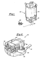
- Figure 1 illustrates a motor removed from a power tool housing and is designated with the reference numeral 10.
- the motor includes a base 12, windings (not shown), commutator 16 and a spider 18.
- a brush assembly 20 is illustrated to couple with the motor spider 18.
- the brush assembly 20 includes a base 22, a housing 24, a spring 26, a brush 28 and an electrical connection 30.
- the base 22 is preferably a non-metallic member having a pair of arms 32 and 34 to secure the base 22 with the motor spider 18.
- the base includes a web 36 which connects the two arms 32 and 34.
- the web includes a recess 38 which receives the housing 24.
- the housing 24 is secured in the recess 38 by flaps 25 which are bent under the base 22 to secure the housing 24 with the base 22.
- the housing 24 includes an open cylindrical member 40 having a rectangular cross-section.
- the cylinder has opened ends 42 and 44, the end 42 being adjacent the commutator 16.
- Slots 46 and 48 are positioned on sides 50 and 52 and extend from open end 44. The slots 46 and 48 enable the spring 26 and electrical connector 30 to move with the brush 28.
- a unitary shunt connection member 60 and connector 62 are formed with housing 24.
- the connector 62 enables an electrical contact to be coupled with the housing 24.
- the connection member 60 has a cutout 61 which interacts with tab 63 to enable positioning of the housing 24 on the base 22.
- the spring 26 is wound about a post 54 extending from the base plate 22.
- the post 54 may be angled off center with respect to the axis of the base 22.
- the spring 26 applies a force onto the brush 28.
- the electrical connector 30 is known in the art as a pigtail connector or shunt.
- the end of the pigtail shunt is ultrasonically welded to the connection member 60.
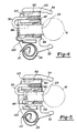
- the brush 28 has a body portion 70 with a pair of ends 72 and 74.
- the body has an overall rectangular cross-section.
- the end 72 is arcuate having several raised and recessed portions 76 and 78 which abut the commutator 16.
- the end 74 includes a recessed portion 80 between a pair of walls 82 and 84.
- the walls 82 and 84 are spaced from one another such that the end of the spring 26 is trapped between the walls 82 and 84 and rides on the surface 86.
- the recessed portion 80 defines a bottom surface 86.
- the surface 86 is angled with respect to a plane transverse to the longitudinal axis 88 of the brush 28.
- the surface 86 is on an angle greater than zero to about ten degrees.
- the surface 86 is angled between greater than zero to about five degrees.
- the angle of the surface 86 is such that the spring 26 applies a substantially constant force on the brush 28 as the brush wears during use.
- a second recess 90 is formed adjacent the first recess 80.
- the second recess 90 is deeper and includes a surface 92 where the pigtail 30 enters the brush 28.
- a stop 100 extends from the brush 28.
- the stop 100 has a width equal to that of the recessed portion surface 86.
- the stop 100 has an angled end 102 which abuts the bottom of housing slot 46 when the brush 28 becomes worn.
- the stop 100 includes a surface 104 which acts to retain the spring end in the recess. Accordingly, the spring end is prevented from dislodging from the brush 28.
- the stop 100 also prohibits the shunt from further travel in the housing to prevent the shunt tip from engaging the commutator and damaging the commutator surface.
- the stop 100 provides an alignment feature as well as a retention feature by prohibiting the brush from further movement toward to commutator.
- the stop may be a bent portion extending from the housing 24 and a groove may be in the brush 28 eliminating the projecting stop 100.
- the recessed portion bottom surface 86 enables the spring end to ride in the recess to provide constant contact with the brush 28.
- This constant contact provides the force which, due to the angle of the surface, provides a substantially constant force on the brush during wear of the brush.
- the constant force eliminates bouncing of the brush and therefore increases the brush wear and prohibits damage to the commutator.
- the spring end, as it is applying the force be as close to the brush as possible. This enhances the application of the constant force on the brush.
- the brush Since the brush has a simple design, it can easily be assembled with the brush assembly by an automated process. Also, the brush assembly may easily be assembled with the motor by an automated process.
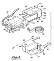
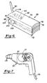
- FIG 7 illustrates a power tool 110, such as a drill motor.
- the power tool 110 includes a housing 112 which receives a motor 10, which is described above.
- the power tool 110 includes an output member 114, in this case a chuck.
- a power cord 116 is coupled with the power tool 110 to supply power.
- the tool 110 may be battery operated.
- Figure 8 illustrates a second embodiment of the present invention Figure 8 is similar to that of Figure 5, with the brush 28' as the only element which is different in this embodiment. Accordingly, the other features are marked with identical reference numerals.
- the brush 28' is the same as that previously illustrated, except that the surface 86' is on an angle substantially steeper than that of the above design.
- the angle is between 20° to 40°.
- the angle is about 30°.
- the present invention enables a bottom surface 86' that can be angled at various positions to enable the constant application of force onto the commutator.
- the spring is near the axis of the brush as it moves from a beginning position to a worn position.
- the present invention provides a number of advantages.
- the present invention provides a brush and brush assembly wherein a substantially constant force is applied to the brush.
- the present invention provides a brush which enables a spring to exert a constant force onto the brush to reduce wear.
- the brush includes a surface where the resultant spring force applied on the surface, by the assembly spring, is substantially the same throughout the life of the brush.
- a stop is present on the brush which prohibits undue wear on the brush by prohibiting further travel of the brush towards the commutator. This likewise prevents the shunt wire from engaging the commutator damaging the commutator surface. Further, the stop prohibits the spring from dislodging from the end of the brush.
Landscapes
- Engineering & Computer Science (AREA)
- Power Engineering (AREA)
- Motor Or Generator Current Collectors (AREA)
- Motor Or Generator Frames (AREA)
Applications Claiming Priority (2)
| Application Number | Priority Date | Filing Date | Title |
|---|---|---|---|
| US09/019,871 US6744170B1 (en) | 1998-02-06 | 1998-02-06 | Brush assembly |
| US19871 | 1998-02-06 |
Publications (3)
| Publication Number | Publication Date |
|---|---|
| EP0935318A2 EP0935318A2 (en) | 1999-08-11 |
| EP0935318A3 EP0935318A3 (en) | 2001-06-27 |
| EP0935318B1 true EP0935318B1 (en) | 2004-08-11 |
Family
ID=21795496
Family Applications (1)
| Application Number | Title | Priority Date | Filing Date |
|---|---|---|---|
| EP99300836A Expired - Lifetime EP0935318B1 (en) | 1998-02-06 | 1999-02-04 | Brush assembly |
Country Status (4)
| Country | Link |
|---|---|
| US (1) | US6744170B1 (enExample) |
| EP (1) | EP0935318B1 (enExample) |
| JP (1) | JPH11275815A (enExample) |
| DE (1) | DE69919239T2 (enExample) |
Cited By (4)
| Publication number | Priority date | Publication date | Assignee | Title |
|---|---|---|---|---|
| US7235005B2 (en) | 2005-03-24 | 2007-06-26 | Black & Decker Inc. | Belt sander |
| US7381118B2 (en) | 2005-03-24 | 2008-06-03 | Black & Decker Inc. | Belt sander |
| US7410412B2 (en) | 2005-01-21 | 2008-08-12 | Black & Decker Inc. | Belt sander |
| US7988538B2 (en) | 2006-10-13 | 2011-08-02 | Black & Decker Inc. | Large angle grinder |
Families Citing this family (29)
| Publication number | Priority date | Publication date | Assignee | Title |
|---|---|---|---|---|
| JP2000116072A (ja) * | 1998-10-01 | 2000-04-21 | Makita Corp | ブラシホルダの取付構造 |
| JP3544347B2 (ja) | 2000-08-29 | 2004-07-21 | 三菱電機株式会社 | 回転電機のブラシホルダ装置 |
| DE10126677A1 (de) * | 2001-06-01 | 2002-12-05 | Bosch Gmbh Robert | Elektrische Kommutatormaschine |
| US6703754B1 (en) * | 2001-10-01 | 2004-03-09 | Ametek, Inc. | Electric motor and brush retaining assembly |
| US6664701B1 (en) * | 2002-06-13 | 2003-12-16 | Black & Decker Inc. | Brush assembly |
| ITBO20020100U1 (it) * | 2002-10-11 | 2004-04-12 | Spal Srl | Gruppo portaspazzole di un motore elettrico |
| US6798109B2 (en) | 2002-10-31 | 2004-09-28 | Black & Decker Inc. | Electric motor brush assembly |
| US6713916B1 (en) | 2002-10-31 | 2004-03-30 | Black & Decker Inc. | Electric motor assembly |
| DE10332302A1 (de) * | 2003-07-16 | 2005-02-17 | Robert Bosch Gmbh | Bürstenanordnung für eine elektrische Maschine |
| US20050162035A1 (en) * | 2004-01-22 | 2005-07-28 | Molon Motor And Coil Corporation | Brush and brush holder assembly for a micro horsepower motor |
| GB0409662D0 (en) | 2004-04-30 | 2004-06-02 | Johnson Electric Sa | Brush assembly |
| DE102004041485A1 (de) * | 2004-08-27 | 2006-03-02 | Robert Bosch Gmbh | Bürstenhalter für eine elektrische Maschine |
| US20070025848A1 (en) * | 2005-07-29 | 2007-02-01 | Shawcross James P | Reduced noise diffuser for a motor-fan assembly |
| US20080084133A1 (en) * | 2006-10-06 | 2008-04-10 | Steven Burton | Dynamoelectric machine brush and method |
| US7466056B2 (en) * | 2006-10-06 | 2008-12-16 | Remi International, Inc | Dynamoelectric machine brush holder assembly and method |
| US7705512B2 (en) * | 2006-10-06 | 2010-04-27 | Remy International, Inc. | Dynamoelectric machine conductor |
| US7696666B2 (en) * | 2006-10-06 | 2010-04-13 | Remy Technologies, L.L.C. | Dynamoelectric machine grommet |
| DE102007057033A1 (de) * | 2007-11-27 | 2009-05-28 | Robert Bosch Gmbh | Elektrisch antreibbare Handwerkzeugmaschine |
| JP2009261097A (ja) * | 2008-04-15 | 2009-11-05 | Asmo Co Ltd | 直流モータ |
| JP4478188B2 (ja) * | 2008-05-19 | 2010-06-09 | 三菱電機株式会社 | ブラシ装置 |
| US7982357B2 (en) * | 2009-02-13 | 2011-07-19 | Remy Technologies, L.L.C. | Brush holder assembly for a dynamo-electric machine |
| KR101789816B1 (ko) | 2010-12-21 | 2017-10-25 | 엘지이노텍 주식회사 | 직류모터의 시트 플레이트 |
| EP2429066B1 (en) * | 2010-09-13 | 2020-04-01 | LG Innotek Co., Ltd. | Sheet plate for DC motor |
| DE102012010481A1 (de) | 2012-05-26 | 2013-11-28 | Brose Fahrzeugteile GmbH & Co. Kommanditgesellschaft, Würzburg | Verfahren zur Herstellung einer Bürste eines Kommutatormotors |
| DE102012212161B4 (de) * | 2012-07-11 | 2025-02-27 | Seg Automotive Germany Gmbh | Elektrisches Bauteil |
| US9093881B2 (en) | 2012-07-20 | 2015-07-28 | Robert Bosch Gmbh | Plastic brush guide |
| FR2996369B1 (fr) * | 2012-09-28 | 2016-06-03 | Valeo Equip Electr Moteur | Cage a balai pour porte-balai de machine electrique et porte-balais correspondant |
| JP2017034730A (ja) * | 2013-12-18 | 2017-02-09 | 日立オートモティブシステムズ株式会社 | 回転電機のブラシ装置および回転電機 |
| FR3032843B1 (fr) * | 2015-02-18 | 2018-06-15 | Valeo Equip Electr Moteur | Porte-balais de moteur electrique |
Family Cites Families (25)
| Publication number | Priority date | Publication date | Assignee | Title |
|---|---|---|---|---|
| US1396451A (en) | 1921-04-11 | 1921-11-08 | Lawrence A Merk | Brush-holder |
| GB392204A (en) | 1931-11-12 | 1933-05-12 | Morgan Crucible Co | Improvements in brushes and brush holders suitable for dynamo electric machines |
| US1970604A (en) | 1932-08-17 | 1934-08-21 | Henrite Products Corp | Brush and holder therefor |
| US2194620A (en) | 1937-10-27 | 1940-03-26 | Emerson Electric Mfg Co | Motor brush assemblage |
| US2474601A (en) | 1948-03-19 | 1949-06-28 | Gen Electric | Brush mechanism |
| US2615939A (en) | 1950-10-02 | 1952-10-28 | Westinghouse Electric Corp | Brush mechanism |
| US2695968A (en) | 1950-11-09 | 1954-11-30 | Eastern Metals Res Co Inc | Commutator with constant tension spring |
| US2802960A (en) | 1955-09-23 | 1957-08-13 | Gen Electric | Brush holder assembly |
| US3108201A (en) | 1960-07-08 | 1963-10-22 | Skil Corp | Brush holder assembly |
| US3480814A (en) | 1968-06-03 | 1969-11-25 | Black & Decker Mfg Co | Brush holder assembly with insert |
| US3656018A (en) | 1970-11-25 | 1972-04-11 | Gen Electric | Brush holder assembly |
| US3784856A (en) * | 1972-07-31 | 1974-01-08 | Gen Electric | Brush holder assembly |
| US3955113A (en) * | 1974-11-27 | 1976-05-04 | General Signal Corporation | Brush holder with means for limiting travel of brush spring |
| US4041339A (en) * | 1975-11-10 | 1977-08-09 | General Motors Corporation | Dynamoelectric machine with brush holding structure |
| US4163167A (en) * | 1977-12-02 | 1979-07-31 | Stackpole Carbon Company | Electric motor brush holder |
| DE3065281D1 (en) | 1979-08-10 | 1983-11-17 | Lucas Ind Plc | Dynamo electric machine brush assembly |
| FR2530877A1 (fr) * | 1982-07-22 | 1984-01-27 | Marchal Equip Auto | Porte-balais et moteur electrique muni d'un tel porte-balais |
| US4593220A (en) * | 1984-07-12 | 1986-06-03 | Black & Decker Inc. | Brush bearing sub-assembly for electric motor |
| US4843274A (en) * | 1985-01-28 | 1989-06-27 | Aircraft Parts Corp. | Brush holder |
| US5198712A (en) | 1992-05-08 | 1993-03-30 | Black & Decker Inc. | Cartridge brush assembly |
| JPH07250457A (ja) * | 1994-03-10 | 1995-09-26 | Jidosha Denki Kogyo Co Ltd | 小型モータ |
| US5717271A (en) * | 1995-01-27 | 1998-02-10 | Mitsuba Corporation | Brush holder device and method of molding same |
| US5664634A (en) * | 1995-10-23 | 1997-09-09 | Waxing Corporation Of America, Inc. | Power tool |
| JP3351698B2 (ja) * | 1996-12-27 | 2002-12-03 | 株式会社ミツバ | ブラシホルダ装置 |
| US5907207A (en) | 1997-11-07 | 1999-05-25 | Ryobi, Ryobi North America, Inc. | Constant force brush spring arrangement for electric motor |
-
1998
- 1998-02-06 US US09/019,871 patent/US6744170B1/en not_active Expired - Fee Related
-
1999
- 1999-02-04 EP EP99300836A patent/EP0935318B1/en not_active Expired - Lifetime
- 1999-02-04 DE DE69919239T patent/DE69919239T2/de not_active Expired - Lifetime
- 1999-02-08 JP JP11029737A patent/JPH11275815A/ja active Pending
Cited By (10)
| Publication number | Priority date | Publication date | Assignee | Title |
|---|---|---|---|---|
| US7410412B2 (en) | 2005-01-21 | 2008-08-12 | Black & Decker Inc. | Belt sander |
| US7235005B2 (en) | 2005-03-24 | 2007-06-26 | Black & Decker Inc. | Belt sander |
| US7381118B2 (en) | 2005-03-24 | 2008-06-03 | Black & Decker Inc. | Belt sander |
| US7503838B2 (en) | 2005-03-24 | 2009-03-17 | Black & Decker Inc. | Belt sander |
| US7837537B2 (en) | 2005-03-24 | 2010-11-23 | Black & Decker Inc. | Belt sander |
| US7846011B2 (en) | 2005-03-24 | 2010-12-07 | Black & Decker Inc. | Belt sander |
| US7871311B2 (en) | 2005-03-24 | 2011-01-18 | Black & Decker Inc. | Belt sander |
| US7997962B2 (en) | 2005-03-24 | 2011-08-16 | Black & Decker Inc. | Belt sander |
| US7988538B2 (en) | 2006-10-13 | 2011-08-02 | Black & Decker Inc. | Large angle grinder |
| US8388417B2 (en) | 2006-10-13 | 2013-03-05 | Black & Decker Inc. | Large angle grinder |
Also Published As
| Publication number | Publication date |
|---|---|
| JPH11275815A (ja) | 1999-10-08 |
| EP0935318A3 (en) | 2001-06-27 |
| EP0935318A2 (en) | 1999-08-11 |
| US6744170B1 (en) | 2004-06-01 |
| DE69919239T2 (de) | 2005-07-28 |
| DE69919239D1 (de) | 2004-09-16 |
Similar Documents
| Publication | Publication Date | Title |
|---|---|---|
| EP0935318B1 (en) | Brush assembly | |
| EP1522127B1 (en) | Brush assembly | |
| JP5214954B2 (ja) | ブラシホルダ用案内枠及びブラシ組立体、並びにブラシ組立体付きブラシホルダを備える電気装置 | |
| US7126242B2 (en) | Electric motor assembly | |
| EP0359603B1 (en) | DC motor with a durable pigtail arrangement | |
| EP0851541A1 (en) | Brush holder device | |
| JPH11275815A5 (enExample) | ||
| CA1131681A (en) | Electric brush holder with brush remnant pivoting and wedging means | |
| US6169351B1 (en) | Brush assembly for dynamoelectric machine | |
| CA2015139A1 (en) | Brush holder for an electric motor | |
| US5563467A (en) | Electromotor brush holders using a punched grid | |
| US7723893B2 (en) | Brush assembly including biasing member for applying force | |
| GB2302999A (en) | Mechanical commutated electric motor | |
| US6271615B1 (en) | Brush holder | |
| JPH079579Y2 (ja) | ブラシアセンブリ | |
| CA1304464C (en) | Low-voltage, high current capacity connector assembly | |
| JP2001339913A (ja) | ブラシホルダ | |
| JPH09201016A (ja) | 回転電機用ブラシ保持装置 | |
| JPS608538Y2 (ja) | 電動機 | |
| US6798110B1 (en) | Brush card | |
| KR830001481Y1 (ko) | 소형 모터 | |
| JPS61180547A (ja) | 小型モ−タのブラシ装置 | |
| KR19980061363U (ko) | 전동공구용 정류자 모터의 카본 브러시 어셈블리 | |
| JP2004320997A (ja) | 定力カートリッジ式ブラシ・ホルダ | |
| JP2000175413A (ja) | 回転電機のブラシ装置 |
Legal Events
| Date | Code | Title | Description |
|---|---|---|---|
| PUAI | Public reference made under article 153(3) epc to a published international application that has entered the european phase |
Free format text: ORIGINAL CODE: 0009012 |
|
| 17P | Request for examination filed |
Effective date: 19990216 |
|
| AK | Designated contracting states |
Kind code of ref document: A2 Designated state(s): DE FR GB IT |
|
| AX | Request for extension of the european patent |
Free format text: AL;LT;LV;MK;RO;SI |
|
| PUAL | Search report despatched |
Free format text: ORIGINAL CODE: 0009013 |
|
| AK | Designated contracting states |
Kind code of ref document: A3 Designated state(s): AT BE CH CY DE DK ES FI FR GB GR IE IT LI LU MC NL PT SE |
|
| AX | Request for extension of the european patent |
Free format text: AL;LT;LV;MK;RO;SI |
|
| RIC1 | Information provided on ipc code assigned before grant |
Free format text: 7H 01R 39/38 A, 7H 02K 5/14 B, 7H 01R 39/40 B |
|
| AKX | Designation fees paid |
Free format text: DE FR GB IT |
|
| 17Q | First examination report despatched |
Effective date: 20030711 |
|
| GRAP | Despatch of communication of intention to grant a patent |
Free format text: ORIGINAL CODE: EPIDOSNIGR1 |
|
| GRAS | Grant fee paid |
Free format text: ORIGINAL CODE: EPIDOSNIGR3 |
|
| GRAA | (expected) grant |
Free format text: ORIGINAL CODE: 0009210 |
|
| AK | Designated contracting states |
Kind code of ref document: B1 Designated state(s): DE FR GB IT |
|
| REG | Reference to a national code |
Ref country code: GB Ref legal event code: FG4D |
|
| REF | Corresponds to: |
Ref document number: 69919239 Country of ref document: DE Date of ref document: 20040916 Kind code of ref document: P |
|
| ET | Fr: translation filed | ||
| PLBE | No opposition filed within time limit |
Free format text: ORIGINAL CODE: 0009261 |
|
| STAA | Information on the status of an ep patent application or granted ep patent |
Free format text: STATUS: NO OPPOSITION FILED WITHIN TIME LIMIT |
|
| 26N | No opposition filed |
Effective date: 20050512 |
|
| PGFP | Annual fee paid to national office [announced via postgrant information from national office to epo] |
Ref country code: FR Payment date: 20120306 Year of fee payment: 14 |
|
| PGFP | Annual fee paid to national office [announced via postgrant information from national office to epo] |
Ref country code: DE Payment date: 20120228 Year of fee payment: 14 |
|
| PGFP | Annual fee paid to national office [announced via postgrant information from national office to epo] |
Ref country code: GB Payment date: 20120224 Year of fee payment: 14 Ref country code: IT Payment date: 20120224 Year of fee payment: 14 |
|
| GBPC | Gb: european patent ceased through non-payment of renewal fee |
Effective date: 20130204 |
|
| REG | Reference to a national code |
Ref country code: FR Ref legal event code: ST Effective date: 20131031 |
|
| PG25 | Lapsed in a contracting state [announced via postgrant information from national office to epo] |
Ref country code: IT Free format text: LAPSE BECAUSE OF NON-PAYMENT OF DUE FEES Effective date: 20130204 |
|
| REG | Reference to a national code |
Ref country code: DE Ref legal event code: R119 Ref document number: 69919239 Country of ref document: DE Effective date: 20130903 |
|
| PG25 | Lapsed in a contracting state [announced via postgrant information from national office to epo] |
Ref country code: DE Free format text: LAPSE BECAUSE OF NON-PAYMENT OF DUE FEES Effective date: 20130903 Ref country code: FR Free format text: LAPSE BECAUSE OF NON-PAYMENT OF DUE FEES Effective date: 20130228 Ref country code: GB Free format text: LAPSE BECAUSE OF NON-PAYMENT OF DUE FEES Effective date: 20130204 |