EP0933120A1 - Installation de traitement de gas d'échappement - Google Patents
Installation de traitement de gas d'échappement Download PDFInfo
- Publication number
- EP0933120A1 EP0933120A1 EP99400206A EP99400206A EP0933120A1 EP 0933120 A1 EP0933120 A1 EP 0933120A1 EP 99400206 A EP99400206 A EP 99400206A EP 99400206 A EP99400206 A EP 99400206A EP 0933120 A1 EP0933120 A1 EP 0933120A1
- Authority
- EP
- European Patent Office
- Prior art keywords
- exhaust gas
- oxygen
- fluorine compound
- air
- enriched air
- Prior art date
- Legal status (The legal status is an assumption and is not a legal conclusion. Google has not performed a legal analysis and makes no representation as to the accuracy of the status listed.)
- Withdrawn
Links
Images

Classifications
-
- B—PERFORMING OPERATIONS; TRANSPORTING
- B01—PHYSICAL OR CHEMICAL PROCESSES OR APPARATUS IN GENERAL
- B01D—SEPARATION
- B01D53/00—Separation of gases or vapours; Recovering vapours of volatile solvents from gases; Chemical or biological purification of waste gases, e.g. engine exhaust gases, smoke, fumes, flue gases, aerosols
- B01D53/22—Separation of gases or vapours; Recovering vapours of volatile solvents from gases; Chemical or biological purification of waste gases, e.g. engine exhaust gases, smoke, fumes, flue gases, aerosols by diffusion
- B01D53/229—Integrated processes (Diffusion and at least one other process, e.g. adsorption, absorption)
-
- B—PERFORMING OPERATIONS; TRANSPORTING
- B01—PHYSICAL OR CHEMICAL PROCESSES OR APPARATUS IN GENERAL
- B01D—SEPARATION
- B01D53/00—Separation of gases or vapours; Recovering vapours of volatile solvents from gases; Chemical or biological purification of waste gases, e.g. engine exhaust gases, smoke, fumes, flue gases, aerosols
- B01D53/34—Chemical or biological purification of waste gases
- B01D53/46—Removing components of defined structure
- B01D53/68—Halogens or halogen compounds
- B01D53/70—Organic halogen compounds
-
- B—PERFORMING OPERATIONS; TRANSPORTING
- B01—PHYSICAL OR CHEMICAL PROCESSES OR APPARATUS IN GENERAL
- B01D—SEPARATION
- B01D53/00—Separation of gases or vapours; Recovering vapours of volatile solvents from gases; Chemical or biological purification of waste gases, e.g. engine exhaust gases, smoke, fumes, flue gases, aerosols
- B01D53/34—Chemical or biological purification of waste gases
- B01D53/46—Removing components of defined structure
- B01D53/68—Halogens or halogen compounds
-
- Y—GENERAL TAGGING OF NEW TECHNOLOGICAL DEVELOPMENTS; GENERAL TAGGING OF CROSS-SECTIONAL TECHNOLOGIES SPANNING OVER SEVERAL SECTIONS OF THE IPC; TECHNICAL SUBJECTS COVERED BY FORMER USPC CROSS-REFERENCE ART COLLECTIONS [XRACs] AND DIGESTS
- Y02—TECHNOLOGIES OR APPLICATIONS FOR MITIGATION OR ADAPTATION AGAINST CLIMATE CHANGE
- Y02C—CAPTURE, STORAGE, SEQUESTRATION OR DISPOSAL OF GREENHOUSE GASES [GHG]
- Y02C20/00—Capture or disposal of greenhouse gases
- Y02C20/30—Capture or disposal of greenhouse gases of perfluorocarbons [PFC], hydrofluorocarbons [HFC] or sulfur hexafluoride [SF6]
-
- Y—GENERAL TAGGING OF NEW TECHNOLOGICAL DEVELOPMENTS; GENERAL TAGGING OF CROSS-SECTIONAL TECHNOLOGIES SPANNING OVER SEVERAL SECTIONS OF THE IPC; TECHNICAL SUBJECTS COVERED BY FORMER USPC CROSS-REFERENCE ART COLLECTIONS [XRACs] AND DIGESTS
- Y02—TECHNOLOGIES OR APPLICATIONS FOR MITIGATION OR ADAPTATION AGAINST CLIMATE CHANGE
- Y02P—CLIMATE CHANGE MITIGATION TECHNOLOGIES IN THE PRODUCTION OR PROCESSING OF GOODS
- Y02P70/00—Climate change mitigation technologies in the production process for final industrial or consumer products
- Y02P70/50—Manufacturing or production processes characterised by the final manufactured product
Definitions
- the present invention relates to an exhaust gas treatment installation and method for decomposing perfluorocarbons such as CHF 3 , SF 6 , NF 3 and the like contained in an exhaust gas discharged from, for example, a semiconductor-manufacturing unit.
- fluorine compound gases for example, perfluorocarbons such as CF 4 , C 2 F 6 , C 3 F 8 and C 4 F 10 , CHF 3 , SF 6 and NF 3 , in the CVD step, etching step or chamber-cleaning step of a semiconductor-manufacturing process.
- the fluorine compound gases mentioned above are generally introduced together with nitrogen gas into a semiconductor-manufacturing unit, and used in an etching or other step and then discharged.
- the exhaust gas therefrom still contains a very small amount of unreacted fluorine compound gases.
- unreacted fluorine compound gases were heretofore simply released to the atmosphere.
- environmental concerns e.g., Earth warming issues, urge the recovery and disposal of the gases. It is believed that the gases may contribute to the destruction of the ozone layer.
- the present invention is intended to provide an exhaust gas treatment installation which can effectively decompose of fluorine compound gases contained in an exhaust gas, specifically by combusting the gases.
- an exhaust gas treatment installation for treating an exhaust gas containing one or more fluorine compound gases and one or more carrier gases, which installation comprises a concentrator for enhancing the concentration of the fluorine compound gases in said exhaust gas, and a combustor for receiving the exhaust gas, in which the concentration of said fluorine compound gases thereof has been enhanced by said concentrator.
- the fluorine compound gases in said exhaust gas are burned by use of air so that they are decomposed.
- the fluorine compound gases shall comprise a gas selected from the group consisting of perfluorocarbons such as CF 4 , C 2 F 6 , C 3 F 8 and C 4 F 10 , CHF 3 , SF 6 , NF 3 , or a mixture thereof.
- the concentration of fluorine compound gases in an exhaust gas is small, i.e., a case where a large amount of carrier gas(es) is contained therein, the major part of the thermal energy in a combustor is absorbed into the carrier gases, and as a result, the decomposing efficiency of the fluorine compound gases is lower. According to the present invention, however, it is possible to burn and decompose fluorine compound gases at a higher efficiency because the concentration of such fluorine compound gases is enhanced before the exhaust gas is introduced into the combustor.
- a membrane separator for removing carrier gas(es) in the exhaust gas.
- the use of a membrane separator has been found to be most effective in enhancing the concentration of fluorine compound gases.
- the exhaust gas treatment installation according to the present invention preferably further comprises an oxygen-enriched air producer for producing oxygen-enriched air, whereby the oxygen-enriched air is used as air to be introduced into the combustor.
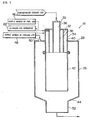
- the combustor preferably comprises a treatment drum, a combustion air inlet pipe fixed at one end of said treatment drum for introducing air, e.g., said oxygen-enriched air, to the inside of said treatment drum as combustion air, a fuel gas inlet pipe disposed inside said combustion air inlet pipe for introducing a fuel gas to the inside of said treatment drum; an exhaust gas inlet pipe disposed inside said fuel gas inlet pipe for introducing the exhaust gas to the inside of said treatment drum; a flame pipe extending from the end of said combustion air inlet pipe on the air outlet side thereof to the vicinity of the other end of said treatment drum; a cooling air inlet means for introducing cooling air into a space between the side wall of said treatment drum and said flame pipe; and an outlet nozzle provided at the other end of said treatment drum for discharging the treated exhaust gas.
- air e.g., said oxygen-enriched air
- the present invention is characterized in that a means for mixing said oxygen-enriched air into the exhaust gas coming from said concentrator is provided between said concentrator and said combustor.
- oxygen-enriched air from a nitrogen gas generator is used for the combustion chamber.
- a nitrogen gas generator using air as a feed material is generally provided.
- nitrogen gas is generated by use of air as a feed material, and particularly in a case where nitrogen is taken out of air by separation, oxygen-enriched air is produced as a result.
- the nitrogen gas generator is used as a source of oxygen-enriched air for the combustion reaction, so that oxygen-enriched air coming from the nitrogen gas generator can be effectively utilized as air for the combustion of the exhaust gas.
- a method for decomposing an exhaust gas containing perfluorocarbons comprises first concentrating the perfluorocarbons in the gas, preferably by membrane separation, and then decomposing the exhaust gas in a combustor.
- the reference numerals refer to the following: 10a, 10b, 10c -- CVD units (a source of exhaust gas), 12 -- pretreatment unit, 14 -- concentrator, 16 --combustor, 18 -- exhaust blower, 20 -- wet scrubber, 22 -- nitrogen gas generator (an oxygen-enriched air producer).
- Fig. 1 shows a preferred embodiment of an exhaust gas treatment installation according to the present invention.
- a plurality of CVD units 10a, 10b, 10c are shown as part of a semiconductor-manufacturing factory, which is a source of exhaust gas.
- the source of exhaust gas there may be contemplated, for instance, etching units, apparatuses for manufacturing liquid crystal devices, or the like, it is not limited to these CVD units.
- an exhaust gas shall comprise CF 4 gas and nitrogen gas (a carrier gas), as used in a CVD process, and contain impurities such as dust and silicon compounds of by-products.
- the exhaust gas treatment installation of the illustrated embodiment comprises a pretreatment unit 12, a concentrator 14, a combustor 16, an exhaust blower 18 and a wet scrubber 20, disposed in series arrangement.
- This exhaust gas treatment installation utilizes oxygen-enriched air, and hence it uses as an oxygen-enriched air producer a nitrogen gas generator 22 placed on site of the semiconductor-manufacturing factory for supplying high purity nitrogen gas to the CVD units 10a, 10b, 10c.
- This pretreatment unit 12 serves to remove impurities in the exhaust gas which may damage the function of said concentrator 14, and it comprises, depending on the kinds of such impurities, a filter, a wet scrubber or dry scrubber or a combination thereof.
- the pretreatment unit 12 is not indispensable, if the impurities are such that they do not damage the function of the concentrator 14 and can be removed by the concentrator 14.
- the exhaust gas which has been freed of impurities by the pretreatment unit 12 is then introduced into the concentrator 14.
- the concentrator 14 serves to separate and remove nitrogen gas (carrier gas) from the exhaust gas so that the concentration of CF 4 gas is enhanced.
- a membrane separation type concentrator is preferable from the viewpoint of higher efficiency of concentration, lower cost and reliability.
- the concentrator see Japanese Patent Application Laid-open (KOKAI) No. 103,633/1997) made by Air Liquide, in France, is effective because it can concentrate CF 4 gas to a concentration of from 15 to 99% in a case where an exhaust gas which is introduced therein still contains from 3,000 to 30, 000 ppm of CF 4 gas.
- the nitrogen gas separated by the concentrator 14 can be released to the atmosphere because it is harmless.
- the exhaust gas in which CF 4 gas has been concentrated (this will be hereinafter called “concentrated exhaust gas") is then mixed, at the point of reference numeral 24 in Fig. 1, with oxygen-enriched air coming from the nitrogen gas generator 22, which is used as an oxygen-enriched air producer.
- the nitrogen gas generator 22 is usually placed in a semiconductor-manufacturing factory, as mentioned above, and it produces oxygen-enriched air as a by-product when generating high purity nitrogen gas from air.
- Oxygen-enriched air from the nitrogen gas generator 22 preferably has an oxygen concentration of about 25% or more.
- the concentrated exhaust gas After the concentrated exhaust gas has been mixed with the oxygen-enriched air, it is introduced into the combustor 16.
- this combustor 16 comprises a cylindrical treatment drum 26, and this treatment drum 26 is vertically placed, and in particular it is placed so that its axis faces in the vertical direction.
- inlet pipes 30, 32, 34 are run through the upper plate 28 of the treatment drum 26 and extend to a predetermined position in the upper inside part of the treatment drum 26. Further, a flame pipe 42 is connected to the lower end of said combustion air inlet pipe 34, and the lower end of said flame pipe 42 extends to the vicinity of a bottom plate 44 of the treatment drum 26.
- the concentrated exhaust gas from the concentrator 14 is destined to come from the upper end of the exhaust gas inlet pipe 30 to the inside thereof.
- a supply source 46 for a fuel gas such as methane gas, natural gas, town gas, propane gas, hydrogen gas, butane gas, or a mixture of them.
- oxygen-enriched air is destined to come, as air for combustion, into the combustion air inlet pipe 34 from the upper part thereof, to which an oxygen-enriched air delivery port of the aforementioned nitrogen gas generator 22 is connected.
- a cooling air supply source 48 is connected to a cooling air inlet port 50 provided on the outer peripheral portion of the upper plate 28 of the treatment drum 26. This cooling air is atmospheric or usual air.
- An outlet nozzle 52 is formed at the central portion of the bottom plate 44 of the treatment drum 26.
- an appropriate ignition means such as an ignition plug is provided on the outlet portion of the fuel gas inlet path 38.
- the ignition means is operated to burn the mixture of the fuel gas and combustion air in the aforementioned construction, its flame will be brought into contact with the concentrated exhaust gas discharged from the lower end of the exhaust gas inlet pipe 30 so that the decomposition of CF 4 gas in the concentrated exhaust gas is effected.
- the flame will run to the vicinity of the bottom plate 44 of the treatment drum 26 owing to the presence of the flame pipe 42.
- air for combustion is oxygen-enriched air
- this oxygen-enriched air is previously mixed into the concentrated exhaust gas
- the flame will spread not only to the outer circumference of the concentrated exhaust gas, but also to the central part thereof.
- the contacting effect of the concentrated exhaust gas and the flame is enhanced, whereby even stable CF 4 gas can be decomposed.
- carbon dioxide (CO 2 ) and hydrogen fluoride (HF) will be produced from the hydrogen and oxygen contained in the fuel gas and air.
- the treated gas in the combustor 16 is removed and sent into the wet scrubber 20 by means of the exhaust blower 18 (Fig. 1).
- HF gas produced by the burning decomposition of CF 4 gas is harmful, but it is removed by the wet scrubber 20, and hence the exhaust gas which is finally discharged to the atmosphere is clean.
- a gas substantially consisting only of CF 4 gas and nitrogen gas has been used as the exhaust gas.
- the exhaust gas to be treated in the present invention it is a specific objective to treat a gas containing at least one additional and/or different fluorine compound gas, for example, of the perfluorocarbons such as C 2 F 6 , C 3 F 8 and C 4 F 10 , CHF 3 , SF 6 and NF 3 , which may destroy the ozone layer.
- the nitrogen gas generator 22 is used as the oxygen-enriched air producer in the aforementioned embodiment, an oxygen-enriched air producer for exclusive use of the treatment installation may be provided.
- the burning decomposition is more effective by previously mixing the oxygen-enriched air into the concentrated exhaust gas before the combustor 16, and then introducing the resulting mixture into the combustor, a sufficient effect can be obtained if the supply point of the oxygen-enriched air is limited to some other point.
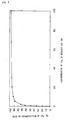
- Fig. 3 is a graph showing the results obtained by carrying out, in practice, an experiment for demonstrating the influence the concentration of CF 4 gas to nitrogen gas has on the efficiency of the burning decomposition of CF 4 gas.
- the flow rate of the gas to be introduced was made constant, i.e. 30 slm, and the flow rates of nitrogen gas and CF 4 gas were varied.
- the combustor one having the structure shown in Fig, 2 was used.
- Oxygen-enriched air having an oxygen concentration of 28% was supplied at a flow rate of 440 slm before the combustor and supplied at a flow rate of 750 slm into the combustor.
- Propane gas was used as a fuel gas for the combustor.
- the rate of decomposition of CF 4 becomes more than 90% when the concentration of CF 4 gas is increased, and in particular when this concentration exceeds about 10%.
- the rate of decomposition decreases rapidly if the concentration of CF 4 gas is lowered to less than 10%. From this result, it can be seen that the efficiency of burning decomposition is remarkably improved by concentrating CF 4 gas to a higher predetermined concentration before the exhaust gas is introduced into the combustor. This result will be also obtained when considering other fluorine compound gases, such as those previously mentioned.
- the following table exhibits the results obtained by simulating, via a computer, variances in the concentration of the respective fluorine compound gases in an exhaust gas, using an exhaust gas treatment installation constructed as shown in Fig. 1.
- Measuring points A, B and C are positions of the reference numerals A, B and C in Fig. 1, respectively. Only nitrogen gas was used as the carrier gases in an exhaust gas. Since the exhaust gas was diluted by a large amount of cooling air at the measuring point C, in addition, the following table exhibits a result obtained as cooling air was excepted. Fluorine comp. in an exhaust gas Concentration (ppm), Measuring point A Concentration (ppm), Measuring point B Concentration (ppm), Measuring point A Ratio of fluorine comp.
- the present invention as has been described above, it is possible to effectively burn and decompose fluorine compound gases such as CF 4 gas and other perfluorocarbons in an exhaust gas discharged, for example, from a semiconductor-manufacturing unit, while using a simple installation construction.
- the present invention therefore contributes much toward avoiding the danger of destroying the ozone layer and preventing Earth warming.
Applications Claiming Priority (2)
| Application Number | Priority Date | Filing Date | Title |
|---|---|---|---|
| JP2230098 | 1998-02-03 | ||
| JP10022300A JPH11218318A (ja) | 1998-02-03 | 1998-02-03 | 排ガス処理設備 |
Publications (1)
| Publication Number | Publication Date |
|---|---|
| EP0933120A1 true EP0933120A1 (fr) | 1999-08-04 |
Family
ID=12078905
Family Applications (1)
| Application Number | Title | Priority Date | Filing Date |
|---|---|---|---|
| EP99400206A Withdrawn EP0933120A1 (fr) | 1998-02-03 | 1999-01-29 | Installation de traitement de gas d'échappement |
Country Status (6)
| Country | Link |
|---|---|
| EP (1) | EP0933120A1 (fr) |
| JP (1) | JPH11218318A (fr) |
| KR (1) | KR19990072340A (fr) |
| IL (1) | IL128313A (fr) |
| SG (1) | SG73609A1 (fr) |
| TW (1) | TW457115B (fr) |
Cited By (7)
| Publication number | Priority date | Publication date | Assignee | Title |
|---|---|---|---|---|
| WO2002074420A1 (fr) * | 2001-03-19 | 2002-09-26 | Advanced Technology Materials, Inc. | Modification apportee a un dispositif integre de lavage de gaz par decomposition et oxydation controlees, consistant en un apport d'air enrichi en oxygene |
| WO2002087732A2 (fr) * | 2001-04-27 | 2002-11-07 | Infineon Technologies Ag | Dispositif central de combustion destine au traitement d'air d'evacuation contenant du pfc |
| WO2003009923A1 (fr) * | 2001-07-23 | 2003-02-06 | Advanced Technology Materials, Inc. | Procede de diminution de monoxyde de carbone lors d'un abattement thermique/humide de composes organiques |
| US6551381B2 (en) * | 2001-07-23 | 2003-04-22 | Advanced Technology Materials, Inc. | Method for carbon monoxide reduction during thermal/wet abatement of organic compounds |
| US7700049B2 (en) | 2005-10-31 | 2010-04-20 | Applied Materials, Inc. | Methods and apparatus for sensing characteristics of the contents of a process abatement reactor |
| US7736599B2 (en) | 2004-11-12 | 2010-06-15 | Applied Materials, Inc. | Reactor design to reduce particle deposition during process abatement |
| RU2453357C1 (ru) * | 2009-12-25 | 2012-06-20 | Мицубиси Хеви Индастриз, Лтд. | Система для выделения co2 и способ выделения co2 |
Families Citing this family (10)
| Publication number | Priority date | Publication date | Assignee | Title |
|---|---|---|---|---|
| JP2001104702A (ja) * | 1999-10-01 | 2001-04-17 | Air Liquide Japan Ltd | ガスの集合回収装置および集合回収方法 |
| KR20010000569A (ko) * | 2000-10-06 | 2001-01-05 | 김형모 | 산소부화방식을 이용한 pfc 처리 시스템 |
| JP4454176B2 (ja) * | 2001-04-20 | 2010-04-21 | Nec液晶テクノロジー株式会社 | Pfcガス燃焼除害装置及びpfcガス燃焼除害方法 |
| JP2007095847A (ja) * | 2005-09-27 | 2007-04-12 | Sanyo Electric Co Ltd | デバイス製造方法およびデバイス製造装置 |
| JP5468216B2 (ja) * | 2008-06-10 | 2014-04-09 | 昭和電工株式会社 | 過弗化物処理装置および過弗化物処理方法 |
| TW201226039A (en) * | 2010-12-31 | 2012-07-01 | Cheng Yuan Environmental Technology Entpr Co Ltd | Gas-collection pipeline and method to reduce the total gas-collection flow quantity |
| JP5622686B2 (ja) * | 2011-08-19 | 2014-11-12 | 大陽日酸株式会社 | 燃焼除害装置 |
| GB2513300B (en) * | 2013-04-04 | 2017-10-11 | Edwards Ltd | Vacuum pumping and abatement system |
| CN113446609A (zh) * | 2021-07-05 | 2021-09-28 | 北京京仪自动化装备技术股份有限公司 | 用于处理半导体制程中产生的清洁气体的系统及方法、装置 |
| KR20230132267A (ko) * | 2022-03-08 | 2023-09-15 | 크라이오에이치앤아이(주) | 배기 가스 처리 장치 |
Citations (5)
| Publication number | Priority date | Publication date | Assignee | Title |
|---|---|---|---|---|
| US5032148A (en) * | 1989-11-07 | 1991-07-16 | Membrane Technology & Research, Inc. | Membrane fractionation process |
| WO1994005399A1 (fr) * | 1992-09-09 | 1994-03-17 | Great Lakes Chemical Corporation | Procede de decomposition d'halocarbones gazeux |
| EP0754487A1 (fr) * | 1995-07-17 | 1997-01-22 | L'air Liquide, Societe Anonyme Pour L'etude Et L'exploitation Des Procedes Georges Claude | Procédé et dispositif pour séparer et récupérer des composés perfluoriques gazeux |
| EP0768109A2 (fr) * | 1995-10-16 | 1997-04-16 | Teisan Kabushiki Kaisha | Dispositif et procédé pour la purification de gaz d'échappement |
| US5858065A (en) * | 1995-07-17 | 1999-01-12 | American Air Liquide | Process and system for separation and recovery of perfluorocompound gases |
Family Cites Families (6)
| Publication number | Priority date | Publication date | Assignee | Title |
|---|---|---|---|---|
| JPS517765A (en) * | 1974-07-10 | 1976-01-22 | Uesuton Kogyo Kk | Tososochiniokeru haikidatsushushorihoho |
| JP3091335B2 (ja) * | 1992-09-30 | 2000-09-25 | 神奈川県 | 爆轟波分解装置 |
| JP2774751B2 (ja) * | 1993-02-18 | 1998-07-09 | 日本ファーネス工業株式会社 | 超低発熱量ガス燃焼装置 |
| JP3277340B2 (ja) * | 1993-04-22 | 2002-04-22 | 日本酸素株式会社 | 半導体製造工場向け各種ガスの製造方法及び装置 |
| JPH08946A (ja) * | 1994-06-22 | 1996-01-09 | Kenichi Nakagawa | 排ガスの脱臭方法 |
| JP3382082B2 (ja) * | 1996-03-15 | 2003-03-04 | 株式会社東芝 | 廃棄物の処理方法および処理装置 |
-
1998
- 1998-02-03 JP JP10022300A patent/JPH11218318A/ja active Pending
-
1999
- 1999-01-26 TW TW088101143A patent/TW457115B/zh not_active IP Right Cessation
- 1999-01-29 EP EP99400206A patent/EP0933120A1/fr not_active Withdrawn
- 1999-02-01 IL IL12831399A patent/IL128313A/en not_active IP Right Cessation
- 1999-02-01 KR KR1019990003185A patent/KR19990072340A/ko not_active Application Discontinuation
- 1999-02-01 SG SG1999000298A patent/SG73609A1/en unknown
Patent Citations (7)
| Publication number | Priority date | Publication date | Assignee | Title |
|---|---|---|---|---|
| US5032148A (en) * | 1989-11-07 | 1991-07-16 | Membrane Technology & Research, Inc. | Membrane fractionation process |
| WO1994005399A1 (fr) * | 1992-09-09 | 1994-03-17 | Great Lakes Chemical Corporation | Procede de decomposition d'halocarbones gazeux |
| EP0754487A1 (fr) * | 1995-07-17 | 1997-01-22 | L'air Liquide, Societe Anonyme Pour L'etude Et L'exploitation Des Procedes Georges Claude | Procédé et dispositif pour séparer et récupérer des composés perfluoriques gazeux |
| JPH09103633A (ja) * | 1995-07-17 | 1997-04-22 | L'air Liquide | パーフルオロ化合物ガスの分離および回収方法および装置 |
| US5858065A (en) * | 1995-07-17 | 1999-01-12 | American Air Liquide | Process and system for separation and recovery of perfluorocompound gases |
| EP0768109A2 (fr) * | 1995-10-16 | 1997-04-16 | Teisan Kabushiki Kaisha | Dispositif et procédé pour la purification de gaz d'échappement |
| JPH09108532A (ja) * | 1995-10-16 | 1997-04-28 | Teisan Kk | 排ガス処理装置 |
Cited By (13)
| Publication number | Priority date | Publication date | Assignee | Title |
|---|---|---|---|---|
| US6527828B2 (en) | 2001-03-19 | 2003-03-04 | Advanced Technology Materials, Inc. | Oxygen enhanced CDA modification to a CDO integrated scrubber |
| WO2002074420A1 (fr) * | 2001-03-19 | 2002-09-26 | Advanced Technology Materials, Inc. | Modification apportee a un dispositif integre de lavage de gaz par decomposition et oxydation controlees, consistant en un apport d'air enrichi en oxygene |
| WO2002087732A2 (fr) * | 2001-04-27 | 2002-11-07 | Infineon Technologies Ag | Dispositif central de combustion destine au traitement d'air d'evacuation contenant du pfc |
| WO2002087732A3 (fr) * | 2001-04-27 | 2003-01-09 | Infineon Technologies Ag | Dispositif central de combustion destine au traitement d'air d'evacuation contenant du pfc |
| US6596054B2 (en) * | 2001-07-23 | 2003-07-22 | Advanced Technology Materials, Inc. | Method for carbon monoxide reduction during thermal/wet abatement of organic compounds |
| US6551381B2 (en) * | 2001-07-23 | 2003-04-22 | Advanced Technology Materials, Inc. | Method for carbon monoxide reduction during thermal/wet abatement of organic compounds |
| WO2003009923A1 (fr) * | 2001-07-23 | 2003-02-06 | Advanced Technology Materials, Inc. | Procede de diminution de monoxyde de carbone lors d'un abattement thermique/humide de composes organiques |
| US7736599B2 (en) | 2004-11-12 | 2010-06-15 | Applied Materials, Inc. | Reactor design to reduce particle deposition during process abatement |
| US7700049B2 (en) | 2005-10-31 | 2010-04-20 | Applied Materials, Inc. | Methods and apparatus for sensing characteristics of the contents of a process abatement reactor |
| US7736600B2 (en) | 2005-10-31 | 2010-06-15 | Applied Materials, Inc. | Apparatus for manufacturing a process abatement reactor |
| RU2453357C1 (ru) * | 2009-12-25 | 2012-06-20 | Мицубиси Хеви Индастриз, Лтд. | Система для выделения co2 и способ выделения co2 |
| US8398758B2 (en) | 2009-12-25 | 2013-03-19 | Mitsubishi Heavy Industries, Ltd. | CO2 recovery system and CO2 recovery method |
| US8974582B2 (en) | 2009-12-25 | 2015-03-10 | Mitsubishi Heavy Industries, Ltd. | CO2 recovery system and CO2 recovery method |
Also Published As
| Publication number | Publication date |
|---|---|
| IL128313A (en) | 2001-09-13 |
| TW457115B (en) | 2001-10-01 |
| IL128313A0 (en) | 2000-01-31 |
| SG73609A1 (en) | 2000-06-20 |
| JPH11218318A (ja) | 1999-08-10 |
| KR19990072340A (ko) | 1999-09-27 |
Similar Documents
| Publication | Publication Date | Title |
|---|---|---|
| EP0933120A1 (fr) | Installation de traitement de gas d'échappement | |
| EP0553643B1 (fr) | Procédé pour le traitement de gaz de combustion | |
| JP3486022B2 (ja) | 排ガス処理装置 | |
| KR100766749B1 (ko) | 과불화화합물 가스를 포함하는 대용량 배기가스 처리방법및 그 처리장치 | |
| TWI434729B (zh) | 用於自氣體流移除氟之方法及裝置 | |
| US9631810B2 (en) | Method of treating an exhaust gas stream | |
| US20050249643A1 (en) | Apparatus and process for the abatement of semiconductor manufacturing effluents containing fluorine gas | |
| US20100258510A1 (en) | Methods and apparatus for treating effluent | |
| KR101879244B1 (ko) | 반도체 폐가스 cf4 처리용 플라즈마 시스템 | |
| WO1996024804A1 (fr) | Procede ameliore d'incineration en circuit ferme | |
| KR20160060116A (ko) | 소각 공정으로부터의 폐기물 기체 스트림의 오존 첨가에 의한 처리 방법 | |
| KR100830797B1 (ko) | 기체 스트림으로부터 유해물질의 제거방법 | |
| BRPI0807585A2 (pt) | Método e aparelho para tratar uma corrente de gás. | |
| KR20110023253A (ko) | 폐냉매 처리 장치 및 방법 | |
| JP6595148B2 (ja) | 排ガスの減圧除害装置 | |
| KR20050075723A (ko) | 불소 발생기로부터 수소를 처리하기 위한 방법 및 장치,및 이 장치를 포함하는 불소 발생기 | |
| CN108970311A (zh) | 一种废气处理工艺 | |
| KR100335737B1 (ko) | 유해개스 처리를 위한 플라즈마 처리 시스템 | |
| KR20160127925A (ko) | 난분해성 유해가스의 처리장치 및 방법 | |
| JPH02126014A (ja) | 有毒性ガスの燃焼処理方法及び装置 | |
| KR101657468B1 (ko) | 난분해성 유해가스의 소각처리를 위한 배가스 전처리 장치 및 그 전처리장치를 이용한 배가스 전처리 방법 | |
| JP2000033365A (ja) | 廃水の処理方法 | |
| KR100553002B1 (ko) | 폐 pfc 가스의 대용량 처리방법 및 장치 | |
| KR200249580Y1 (ko) | 고농도 산소를 이용한 폐기물 소각물 완전 연소 및고농도 폐수 농축 소각 장치 | |
| CN105579116A (zh) | 通过添加臭氧处理来自焚化过程的废气流的方法 |
Legal Events
| Date | Code | Title | Description |
|---|---|---|---|
| PUAI | Public reference made under article 153(3) epc to a published international application that has entered the european phase |
Free format text: ORIGINAL CODE: 0009012 |
|
| AK | Designated contracting states |
Kind code of ref document: A1 Designated state(s): DE FR GB IE IT |
|
| AX | Request for extension of the european patent |
Free format text: AL;LT;LV;MK;RO;SI |
|
| RIN1 | Information on inventor provided before grant (corrected) |
Inventor name: FUKUOKA, MUNEYUKI Inventor name: IBARAKI, YOSHIHIRO Inventor name: NOZAWA, SHIGEYOSHI |
|
| 17P | Request for examination filed |
Effective date: 20000204 |
|
| AKX | Designation fees paid |
Free format text: DE FR GB IE IT |
|
| RAP1 | Party data changed (applicant data changed or rights of an application transferred) |
Owner name: L'AIR LIQUIDE, S.A. A DIRECTOIRE ET CONSEIL DE SUR |
|
| STAA | Information on the status of an ep patent application or granted ep patent |
Free format text: STATUS: THE APPLICATION IS DEEMED TO BE WITHDRAWN |
|
| 18D | Application deemed to be withdrawn |
Effective date: 20030909 |