EP0931695A2 - Kopfstütze für Fahrzeugsitze - Google Patents
Kopfstütze für Fahrzeugsitze Download PDFInfo
- Publication number
- EP0931695A2 EP0931695A2 EP99101192A EP99101192A EP0931695A2 EP 0931695 A2 EP0931695 A2 EP 0931695A2 EP 99101192 A EP99101192 A EP 99101192A EP 99101192 A EP99101192 A EP 99101192A EP 0931695 A2 EP0931695 A2 EP 0931695A2
- Authority
- EP
- European Patent Office
- Prior art keywords
- headrest according
- axial
- seat back
- guide part
- bolt
- Prior art date
- Legal status (The legal status is an assumption and is not a legal conclusion. Google has not performed a legal analysis and makes no representation as to the accuracy of the status listed.)
- Granted
Links
- 238000003780 insertion Methods 0.000 claims abstract description 9
- 230000037431 insertion Effects 0.000 claims abstract description 9
- 230000005484 gravity Effects 0.000 claims description 3
- 230000004323 axial length Effects 0.000 claims description 2
- 230000000149 penetrating effect Effects 0.000 claims 1
- 238000010276 construction Methods 0.000 description 5
- 238000013461 design Methods 0.000 description 3
- 238000013459 approach Methods 0.000 description 1
- 230000006835 compression Effects 0.000 description 1
- 238000007906 compression Methods 0.000 description 1
- 230000008878 coupling Effects 0.000 description 1
- 238000010168 coupling process Methods 0.000 description 1
- 238000005859 coupling reaction Methods 0.000 description 1
- 230000000994 depressogenic effect Effects 0.000 description 1
- 238000002347 injection Methods 0.000 description 1
- 239000007924 injection Substances 0.000 description 1
- 230000002093 peripheral effect Effects 0.000 description 1
- 238000012549 training Methods 0.000 description 1
Images
Classifications
-
- B—PERFORMING OPERATIONS; TRANSPORTING
- B60—VEHICLES IN GENERAL
- B60N—SEATS SPECIALLY ADAPTED FOR VEHICLES; VEHICLE PASSENGER ACCOMMODATION NOT OTHERWISE PROVIDED FOR
- B60N2/00—Seats specially adapted for vehicles; Arrangement or mounting of seats in vehicles
- B60N2/80—Head-rests
- B60N2/806—Head-rests movable or adjustable
- B60N2/809—Head-rests movable or adjustable vertically slidable
- B60N2/812—Head-rests movable or adjustable vertically slidable characterised by their locking devices
- B60N2/818—Head-rests movable or adjustable vertically slidable characterised by their locking devices with stepwise positioning
Definitions
- the invention relates to a headrest for vehicle seats according to the preamble of the claim 1.
- a headrest which two the cushion support Has (head box) supporting bars, whose insertion areas each in one a seat back held guide part are, for example, in DE 36 36 931 C1 described.
- Such fastened in the support frame of a seat back Guide parts or guide sleeves are used for headrests with axial height adjustment within the Head box (with height-adjustable headrests inside So) only the releasable attachment of the support rods.
- the one not for narrower type of height-adjustable headrest for a vehicle seat are the insertion areas two carrying rods on one by means of one Screw drive height-adjustable crossbar locked and otherwise at two with their longitudinal openings to each other facing half-shells one in the seat back attached frame immediately slid.
- the Headrest according to DE 80 09 153 Ul required a considerable construction effort.
- the invention is based on the object develop known headrest so that the axial height adjustment of a headrest with a operated relatively simple construction effort can be.
- this object solved in that at least the insertion area of the Support rod in a lockable on the support rod Sliding sleeve is included that the sliding sleeve in turn in the guide part defined in the seat back axially movable and lockable, that a driver projection held by the sliding sleeve which is the guide part in an axial slot enforced and which by means of a drive is reciprocable in the axial direction.
- a sliding sleeve which locks the insertion area of the support rod picks up in the attached in the seat back construction Guide part, which also expediently sleeve-like can be formed axially movable or telescopic and also lockable.
- the sliding sleeve has one transverse to the axial direction outstanding driving lead on which the Guide part in an axial slot to the outside interspersed and there the possibility of one Offers drive. In this way, the Carrying rod (and thus the headrest) carrying sliding sleeve with a relatively low construction effort back and forth over the driver projection or on and be moved.
- the invention Use the headrest wherever there is a seat back Height adjustment generally with one drive, even if only with an external manual drive should be.
- the headrest according to the invention can primarily lean in connection with foldable seat use it especially when it comes to rear seats acts, in their maximum height position headrests can be used to fold the seat back forward would hinder.
- the support rod is axially adjustable relative to the sliding sleeve and releasable in axial adjustment positions can be locked.
- This training according to the invention permitted, especially in connection with a foldable Seat back, the advantage of being unique once height adjustment made by the passenger automatically re-adjusts when the head restraint follows the swiveling back (into the upright position) of the The seat back is extended upwards.
- the plug-in area expediently has the Support rod distanced from each other in the axial direction Locking notches, locking grooves or the like, in which one of locking element held by the sliding sleeve, e.g. an approximately radially movable detent spring, releasably locking intervenes.
- one of locking element held by the sliding sleeve e.g. an approximately radially movable detent spring, releasably locking intervenes.
- the axial stops to realize is that the axial slot only over an axial partial length of the Guide part extends, and that the axial slot two distanced from each other with its axial slot length
- a preferred variant of the invention exists in that in the same cross section of the guide part the circumferential extent of the axial slot is less is as the unslotted peripheral area of the guide member. This means that the cross section of the Undercut the guide part in the area of the axial slot is, so the support bar almost over their entire circumference laterally or radially can support.
- a particularly robust guide part is achieved according to the invention when the to two axial stops adjacent axial areas of the Guide part one in the circumferential direction have closed cross-section.
- the movement of the sliding sleeve takes place expediently such that the driver projection means Manual drive via one arranged on the outside of the seat back Actuating element, such as operating lever or Operating slide, is movable.
- the Driver projection in its upper or outer Position in the stop by means of a seat back to hold the latch releasably is.
- This latch can be used as a driver projection with a bolt recess underneath Swivel latch be formed.
- the bolt can only be unlocked against the spring return force.
- the mechanical connection is advantageous is a control element, which the bolt only in Unlocking direction actuated.
- a particularly useful design according to the invention is that the as Swivel bolts trained bolts a control surface with which a counter control surface of the Control element in the unlocking direction of the swing bolt cooperates. As soon as the control element is actuated , its counter-control surface slides on the control surface along the swivel bar and swings it in the unlocked position. This gives the driver a head start released, so that the Move the sliding sleeve bearing the headrest down can.
- the control element expediently forms a lever, in particular a control lever in the form of a two-armed Lever.
- the invention provides that between the actuator and the bolt mechanical connection located also the movement of the driver projection.
- the mechanical Connection is also from the control member educated. However, this can give the driver a head start only move towards its upper or outer stop.
- the Invention particularly advantageous in the case of foldable seat backrests, in particular from rear seats.
- the invention provides that in connection with a foldable headrest Seat backrest the drive movement for the driver projection (if necessary, including the drive for the Latch), especially for the driver projection actuating mechanical connection, e.g. for the Control element, from the folding movement of the seat back is derived.
- the seat back latch handle a double function that once is to lock the tab and at the same time the bolt connection between the seat back and Loosen seat and on the other hand with a counter movement Driver projection and sliding sleeve (and thus headrest) to the extended height position set back.
- a convenient way to lock the seat back with the unlocking and actuation of the To connect the driver projection is that the locking member is mounted on the foot of the seat back Rotary trap, especially fork trap, which with interacts with a locking bolt attached to the seat, and that of the rotary movement of the catch Actuation movement of the mechanical connection, in particular of the control element is derived.
- the control element e.g. the control lever, connected to the catch by means of a handlebar.
- the invention is basically independent how many support rods a headrest has.
- the invention can of course also be applied if the headrest is only on one Support rod is guided.
- the vast number of Headrests are provided with two support rods, for which the invention is a guide part and a double arrangement having a sliding sleeve provides, in which both point to each other, each have an axial slot of a guide part assertive, driver tabs to one the traverse connecting the two sliding sleeves are united.
- Such a driving crossbar is, as already mentioned, from one to another narrower type headrest known per se (see DE 80 09 153 U1).
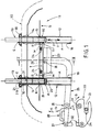
- Fig. 1 is the upper contour of a seat back 10 indicated with a broken line. From the support frame 11 of the seat back 10, only the upper cross member 13 is closed see which openings 14, 15 have in which Guide sleeves 12 are attached.
- each guide sleeve 12 There is a sliding sleeve 16 in each guide sleeve 12 added, each up towards y or is movable downwards in the direction z.
- the guide part 12 forms adjacent to the apex the seat back 10 has an approximately flange-like collar 39.
- Each guide sleeve 12 has between an upper Axial stop 17 and a lower axial stop 18 each have an axial slot A.
- Spring restoring forces P for example in the form of tension or compression springs, load the crossbar T in Direction z down.
- Spring restoring forces P for example in the form of tension or compression springs, load the crossbar T in Direction z down.
- Detent spring R is one in the left half of the image Detent spring R indicated, which in the sliding sleeve 16th axially fixed, but in the radial direction is resiliently movable. 1 engages the detent spring R in a locking groove 20 and thus prevents that the support rod 19 involuntarily in the y direction upwards can be pulled out of the sliding nozzle 16.
- the support rod 19 can accordingly the individual wishes of a passenger in the direction z gradually down and back up be moved, the detent spring R with each an adjustment notch 21 cooperates.
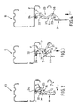
- the traverse is located T in its highest in direction y Position and is within the bolt opening 22nd of the pivot bolt 23 locked.
- the pivot bolt 23 is on the underside of the crossbar by means of a pivot bearing 24 13 pivotally arranged on this.
- the locking direction of the swing bolt 23 is marked with u; the unlocking direction of the Swivel lock 23 is designated by v.
- the swivel plane of the pivot bolt 23 extends parallel to the plane of the drawing of Figs. 2-4.
- the swivel bolt 23 is by a spring restoring force F, for example by a leg spring arranged on the pivot bearing 24 (not shown), in the locking direction u charged.
- the swivel plane one as a two-armed lever trained control lever 25 extends according to Fig. 1 parallel to the plane of the drawing. According to the Fig. 2-4 extends the pivot plane of the control lever 25 perpendicular to the plane of the drawing.
- the control lever 25 is in a pivot bearing 26 Support frame 11 of the seat back 10 pivoted.
- a seat back latch handle 28 indicated schematically.
- the seat back latch handle 28 can along the pivot direction a lifted up and along the opposite Swivel direction b are depressed.
- control lever 25 the crossbar T with a positive connection 29 only grips under pressure.
- Raising the seat back latch handle 28 in Direction a initially has the consequence that one over a Rotary bearing 31 arranged on the support frame 11 of the seat back 10 Fork latch 30 rotated in direction g (i.e. is opened) because the free end of the operating arm 27 of the control lever 25 via a handlebar (Coupling) 32 with the free end of the fork latch 30 is connected to results.
- the latch opening 33 of the fork latch catches in the direction g 30 out of engagement with that on the seat frame (not shown) attached locking bolt 34 so that the Seat back 10 is unlocked and therefore in the direction of travel can be folded forward.
- the fork latch 30 is by means of a spring (not shown) in its direction g pivoted opening position held, which in Fig. 1st is not shown. This also means that because of the movement connection of the handlebar 32 with itself fork latch located in the unlocked position 30 at the same time the constellation of the components 23, 25, T, 4 is present.
- the control lever 25 moves with his Form-fit receptacle 29 upwards in the direction y and also pushes the crossbar T upwards.
- the control lever 25 slides with its control nose 38 along a lower control surface 37 of the Swivel lock 23, pivoted the latter initially counter to the spring return force F in the unlocking direction v until finally about the intermediate phase 3, the starting position shown in Fig. 2 is reached.
- the adjustment device shown as far as it is is appropriate, largely using Plastic injection molded parts (e.g. guide part 12 and Sliding sleeve 16) manufactured.
Landscapes
- Engineering & Computer Science (AREA)
- Aviation & Aerospace Engineering (AREA)
- Transportation (AREA)
- Mechanical Engineering (AREA)
- Seats For Vehicles (AREA)
- Chair Legs, Seat Parts, And Backrests (AREA)
Abstract
Description
Claims (30)
- Kopfstütze für Fahrzeugsitze mit mindestens einer einen Polsterträger haltenden Tragstange (19), deren Einsteckbereich (E) in einem in einer Sitzlehne (10) gehaltenen Führungsteil (12) mindestens mittelbar aufgenommen ist, dadurch gekennzeichnet, daß zumindest der Einsteckbereich (E) der Tragstange (19) in einer auf der Tragstange (19) arretierbaren Gleithülse (16) aufgenommen ist, daß die Gleithülse (16) ihrerseits in dem in der Sitzlehne (10) festgelegten Führungsteil (12) axial beweglich und arretierbar aufgenommen ist, daß von der Gleithülse (16) ein Mitnehmervorsprung (M) gehalten ist, welcher das Führungsteil (12) in einem Axialschlitz (A) durchsetzt und welcher mittels eines Antriebs (bei 28) in Axialrichtung (y, z) hin- und herbewegbar ist.
- Kopfstütze nach Anspruch 1, dadurch gekennzeichnet, daß die Tragstange (19) relativ zur Gleithülse (16) axial verstellbar und in axialen Verstellpositionen lösbar arretierbar ist.
- Kopfstütze nach Anspruch 2, dadurch gekennzeichnet, daß der Einsteckbereich (E) der Tragstange (19) in Axialrichtung (y, z) voneinander distanzierte Rastkerben, Rastnuten od. dgl. (20, 21), aufweist, in welche ein von der Gleithülse (16) gehaltenes Arretierelement, wie z.B. eine etwa radial bewegliche Rastfeder (R), lösbar arretierend eingreift.
- Kopfstütze nach einem der Ansprüche 1 bis 3, dadurch gekennzeichnet, daß der Axialschlitz (A) sich nur über eine axiale Teillänge des Führungsteils (12) erstreckt, und daß der Axialschlitz (A) zwei mit seiner Axialschlitzlänge voneinander distanzierte Axialanschläge (17, 18) für den von der Gleithülse (16) gehaltenen Mitnehmervorsprung (M) bildet, von denen der eine Anschlag der untere bzw. innere Axialanschlag (17) und der andere der obere bzw. äußere Axialanschlag (18) ist.
- Kopfstütze nach einem der Ansprüche 1 bis 4, dadurch gekennzeichnet, daß in demselben Querschnitt des Führungsteils (12) die Umfangserstreckung des Axialschlitzes (A) geringer ist als der ungeschlitzte Umfangsbereich des Führungsteils (12).
- Kopfstütze nach Anspruch 4 oder nach Anspruch 5, dadurch gekennzeichnet, daß die an die beiden Axialanschläge (17, 18) angrenzenden Axialbereiche des Führungsteils (12) jeweils einen in Umfangsrichtung geschlossenen Querschnitt aufweisen.
- Kopfstütze nach einem der Ansprüche 1 bis 6, dadurch gekennzeichnet, daß der Axialschlitz (A) sich überwiegend im unteren bzw. inneren Axialbereich des Führungsteils (12) befindet.
- Kopfstütze nach einem der Ansprüche 1 bis 7, dadurch gekennzeichnet, daß Führungsteil (12) und Gleithülse (16) jeweils einen geraden Kreiszylinder bilden.
- Kopfstütze nach einem der Ansprüche 1 bis 8, dadurch gekennzeichnet, daß das Führungsteil (12) benachbart dem Scheitel der Sitzlehne (10) einen etwa flanschartigen Kragen (39) bildet.
- Kopfstütze nach einem der Ansprüche 1 bis 9, dadurch gekennzeichnet, daß die Gleithülse (16) auf ihrer gesamten axialen Länge durchgehend denselben Querschnitt aufweist.
- Kopfstütze nach einem der Ansprüche 1 bis 10, dadurch gekennzeichnet, daß der Mitnehmervorsprung (M) mittels Handantrieb über ein außen an der Sitzlehne (10) angeordnetes Betätigungselement (28), wie Betätigungshebel oder Betätigungsschieber, bewegbar ist.
- Kopfstütze nach einem der Ansprüche 1 bis 11, dadurch gekennzeichnet, daß der Mitnehmervorsprung (M) in seiner am oberen bzw. äußeren Anschlag (17) anliegenden Position mittels eines sitzlehnenseitig gehaltenen Riegels (23) lösbar zu arretieren ist.
- Kopfstütze nach Anspruch 12, dadurch gekennzeichnet, daß der Riegel ein den Mitnehmervorsprung (M) mit einer Riegelaussparung (22)untergreifender Schwenkriegel (23) ist.
- Kopfstütze nach Anspruch 12 oder nach Anspruch 13, dadurch gekennzeichnet, daß der Riegel (23) entgegen Federrückstellkraft (F) entriegelbar ist.
- Kopfstütze nach einem der Ansprüche 1 bis 14, dadurch gekennzeichnet, daß die Gleithülse (16) nach unten bzw. bezüglich der Sitzlehne nach innen (Richtung z) durch Schwerkraft belastet ist.
- Kopfstütze nach einem der Ansprüche 1 bis 15, dadurch gekennzeichnet, daß die Gleithülse (16) in Axialrichtung nach innen bzw. nach unten (Richtung z) mittels Federrückstellkraft (P) belastet ist.
- Kopfstütze nach einem der Ansprüche 12 bis 16, dadurch gekennzeichnet, daß der Riegel (23) unter Zwischenschaltung einer mechanischen Verbindung (25) mittels des Betätigungselements (28) betätigbar ist.
- Kopfstütze nach Anspruch 17, dadurch gekennzeichnet, daß die mechanische Verbindung ein Steuerglied (25) ist, welches den Riegel (23) nur in Entriegelungsrichtung (v) betätigt.
- Kopfstütze nach Anspruch 18, dadurch gekennzeichnet, daß der als Schwenkriegel (23) ausgebildete Riegel eine Steuerfläche (36) aufweist, mit welcher eine Gegensteuerfläche (35) des Steuergliedes (25) im Entriegelungssinne des Schwenkriegels (23) zusammenwirkt.
- Kopfstütze nach Anspruch 19, dadurch gekennzeichnet, daß das Steuerglied mindestens einen Hebel (25) bildet.
- Kopfstütze nach Anspruch 20, dadurch gekennzeichnet, daß das Steuerglied einen Steuerhebel (25) in Form eines zweiarmigen Hebels bildet.
- Kopfstütze nach einem der Ansprüche 17 bis 21, dadurch gekennzeichnet, daß die zwischen dem Betätigungselement (28) und dem Riegel (23) befindliche mechanische Verbindung (25) auch der Betätigung des Mitnehmervorsprungs (M) dient.
- Kopfstütze nach einem der Ansprüche 17 bis 22, dadurch gekennzeichnet, daß die der Betätigung des Mitnehmervorsprungs (M) dienende mechanische Verbindung ebenfalls von dem Steuerglied (25) gebildet ist, welches den Mitnehmervorsprung (M) nur zu seinem oberen bzw. äußeren Anschlag (17) hin bewegt.
- Kopfstütze nach Anspruch 23, dadurch gekennzeichnet, daß das Steuerglied (25) über eine Formschlußaufnahme (29), welche den Mitnehmervorsprung (M) untergreift, mit letzterem lediglich druckfest gekuppelt ist.
- Kopfstütze nach einem der Ansprüche 11 bis 24, dadurch gekennzeichnet, daß im Zusammenhang mit einer die Kopfstütze tragenden klappbaren Sitzlehne (10) die Antriebsbewegung für den Mitnehmervorsprung (M), insbesondere für die den Mitnehmervorsprung (M) betätigende mechanische Verbindung, wie z.B. für das Steuerglied (25), von der Klappbewegung der Sitzlehne (10) abgeleitet ist.
- Kopfstütze nach einem der Ansprüche 11 bis 25, dadurch gekennzeichnet, daß im Zusammenhang mit einer die Kopfstütze tragenden klappbaren Sitzlehne (10) das Betätigungselement von einem Sitzlehnen-Riegelgriff (28) gebildet ist, welcher sowohl die mechanische Verbindung, insbesondere das Steuerglied (25), als auch ein zwischen Sitz (bei 34) und klappbarer Sitzlehne (10) wirksames Riegelglied (30) betätigt.
- Kopfstütze nach Anspruch 26, dadurch gekennzeichnet, daß das Riegelglied eine am Fuß der Sitzlehne (10) gelagerte Drehfalle (30), insbesondere Gabelfalle, bildet, welche mit einem am Sitz befestigten Schließbolzen (34) zusammenwirkt, und daß von der Drehbewegung der Drehfalle (30) die Betätigungsbewegung der mechanischen Verbindung, insbesondere des Steuergliedes (25), abgeleitet ist.
- Kopfstütze nach Anspruch 27, dadurch gekennzeichnet, daß das Steuerglied, wie z.B. der Steuerhebel (25), mittels eines Lenkers (32) mit der Drehfalle (30) bewegungsverbunden ist.
- Kopfstütze nach einem der Ansprüche 1 bis 28, gekennzeichnet durch eine zwei Tragstangen (19) mit jeweils einem Führungsteil (12) und einer Gleithülse (16) aufweisende Doppelanordnung (s.Fig. 1), bei welcher beide zueinander weisenden, jeweils einen Axialschlitz (A) eines Führungsteils (12) durchsetzenden, Mitnehmervorsprünge (M) zu einer die beiden Gleithülsen (16) miteinander verbindenden Mitnehmertraverse (T) vereinigt sind.
- Kopfstütze nach einem der Ansprüche 1 bis 29, insbesondere nach den Ansprüchen 1 bis 3, dadurch gekennzeichnet, daß der Mitnehmervorsprung (M) zwischen zwei in Axialrichtung (y, z) voneinander distanzierten Axialanschlägen (17, 18) bewegbar ist.
Applications Claiming Priority (2)
| Application Number | Priority Date | Filing Date | Title |
|---|---|---|---|
| DE19802515A DE19802515A1 (de) | 1998-01-24 | 1998-01-24 | Kopfstütze für Fahrzeugsitze |
| DE19802515 | 1998-01-24 |
Publications (3)
| Publication Number | Publication Date |
|---|---|
| EP0931695A2 true EP0931695A2 (de) | 1999-07-28 |
| EP0931695A3 EP0931695A3 (de) | 2000-03-29 |
| EP0931695B1 EP0931695B1 (de) | 2004-06-02 |
Family
ID=7855462
Family Applications (1)
| Application Number | Title | Priority Date | Filing Date |
|---|---|---|---|
| EP99101192A Expired - Lifetime EP0931695B1 (de) | 1998-01-24 | 1999-01-22 | Kopfstütze für Fahrzeugsitze |
Country Status (3)
| Country | Link |
|---|---|
| EP (1) | EP0931695B1 (de) |
| DE (2) | DE19802515A1 (de) |
| ES (1) | ES2221240T3 (de) |
Cited By (1)
| Publication number | Priority date | Publication date | Assignee | Title |
|---|---|---|---|---|
| DE10153058A1 (de) * | 2001-10-30 | 2003-05-22 | Grammer Ag | Fahrzeugsitz mit Kopfstütze |
Families Citing this family (2)
| Publication number | Priority date | Publication date | Assignee | Title |
|---|---|---|---|---|
| RU2186695C2 (ru) * | 2000-02-08 | 2002-08-10 | Открытое акционерное общество "АВТОВАЗ" | Направляющая втулка с фиксирующим устройством для подголовника сиденья транспортного средства |
| DE102015214990B4 (de) * | 2015-08-06 | 2024-09-12 | Adient Us Llc | Führungshülse für einen Fahrzeugsitz, Fahrzeugsitz und Verfahren zur Herstellung einer Führungshülse |
Citations (2)
| Publication number | Priority date | Publication date | Assignee | Title |
|---|---|---|---|---|
| DE8009153U1 (de) | 1980-04-02 | 1980-06-26 | Keiper Automobiltechnik Gmbh & Co Kg, 5630 Remscheid | Hoehenverstellbare kopfstuetze fuer einen fahrzeugsitz |
| DE3636931C1 (de) | 1986-10-30 | 1988-06-23 | Butz Eugen Otto | Kopfstuetze fuer Kraftfahrzeugsitze |
Family Cites Families (2)
| Publication number | Priority date | Publication date | Assignee | Title |
|---|---|---|---|---|
| DE19628861B4 (de) * | 1996-07-17 | 2005-06-09 | Bayerische Motoren Werke Ag | Fahrzeugsitz, insbesondere für einen Personenkraftwagen |
| DE19632560C2 (de) * | 1996-08-13 | 1998-07-02 | Grammer Ag | Kopfstützen-Arretiereinrichtung |
-
1998
- 1998-01-24 DE DE19802515A patent/DE19802515A1/de not_active Withdrawn
-
1999
- 1999-01-22 EP EP99101192A patent/EP0931695B1/de not_active Expired - Lifetime
- 1999-01-22 ES ES99101192T patent/ES2221240T3/es not_active Expired - Lifetime
- 1999-01-22 DE DE59909619T patent/DE59909619D1/de not_active Expired - Fee Related
Patent Citations (2)
| Publication number | Priority date | Publication date | Assignee | Title |
|---|---|---|---|---|
| DE8009153U1 (de) | 1980-04-02 | 1980-06-26 | Keiper Automobiltechnik Gmbh & Co Kg, 5630 Remscheid | Hoehenverstellbare kopfstuetze fuer einen fahrzeugsitz |
| DE3636931C1 (de) | 1986-10-30 | 1988-06-23 | Butz Eugen Otto | Kopfstuetze fuer Kraftfahrzeugsitze |
Cited By (2)
| Publication number | Priority date | Publication date | Assignee | Title |
|---|---|---|---|---|
| DE10153058A1 (de) * | 2001-10-30 | 2003-05-22 | Grammer Ag | Fahrzeugsitz mit Kopfstütze |
| DE10153058B4 (de) * | 2001-10-30 | 2011-01-13 | Grammer Ag | Fahrzeugsitz mit Kopfstütze |
Also Published As
| Publication number | Publication date |
|---|---|
| DE59909619D1 (de) | 2004-07-08 |
| DE19802515A1 (de) | 1999-07-29 |
| EP0931695A3 (de) | 2000-03-29 |
| ES2221240T3 (es) | 2004-12-16 |
| EP0931695B1 (de) | 2004-06-02 |
Similar Documents
| Publication | Publication Date | Title |
|---|---|---|
| DE3605774C2 (de) | ||
| DE60304991T2 (de) | Kopfstütze für kraftfahrzeuge | |
| EP0082436A2 (de) | Fahrzeugsitz, insbesondere Kraftfahrzeugsitz | |
| DE19510618A1 (de) | Kraftfahrzeugsitz, der im vorgeklappten Zustand der Rückenlehne längsverschiebbar ist | |
| DE3636931C1 (de) | Kopfstuetze fuer Kraftfahrzeugsitze | |
| EP2768697B1 (de) | Verriegelungs- und neigungsverstellanordnung, insbesondere lehnenschloss | |
| DE19603911A1 (de) | Klappbare Rückenlehne mit höheneinstellbarer Kopfstütze | |
| DE102004017688A1 (de) | Kopfstütze für Automobilsitze | |
| EP1577154A2 (de) | Fahrzeugsitz mit einer schwenkbar gelagerten kopfstütze | |
| DE10313807B4 (de) | Fahrzeugsitz | |
| DE102008017712A1 (de) | Kraftfahrzeugsitz mit arretierbarer Flügellehne und Sitzanordnung mit einem solchen Kraftfahrzeugsitz | |
| DE202009013635U1 (de) | Kopfstütze für Fahrzeuge | |
| EP0931695B1 (de) | Kopfstütze für Fahrzeugsitze | |
| DE19517932C2 (de) | Kraftfahrzeug-Rücksitz mit Kopfstütze | |
| DE19737706C1 (de) | Höhenverstellbare Kopfstütze, insbesondere für Kraftfahrzeugsitze | |
| DE19730616C2 (de) | Höhenverstellbare Kopfstütze, insbesondere für einen Kraftfahrzeugsitz | |
| DE4330448C2 (de) | Armlehne für Kraftfahrzeugsitze | |
| DE3933817C1 (en) | Folding chair for auditorium - has connection to adjacent chair with locking piece forming slide plate | |
| DE29801021U1 (de) | Kopfstütze für Fahrzeugsitze | |
| EP4139164B1 (de) | Kopfstütze für einen sitz und fahrzeugsitz | |
| DE19644021C2 (de) | Spindelantrieb für Kfz-Sitze oder deren Teile | |
| DE4443527C2 (de) | Kopfstütze | |
| DE10157322B4 (de) | Kopfstütze für Fahrzeugsitze | |
| DE10261689A1 (de) | Kraftfahrzeugsitz und Kraftfahrzeugsitzbank | |
| DE19524832C2 (de) | Fahrzeugsitz |
Legal Events
| Date | Code | Title | Description |
|---|---|---|---|
| PUAI | Public reference made under article 153(3) epc to a published international application that has entered the european phase |
Free format text: ORIGINAL CODE: 0009012 |
|
| AK | Designated contracting states |
Kind code of ref document: A2 Designated state(s): DE ES FR GB IT SE |
|
| AX | Request for extension of the european patent |
Free format text: AL;LT;LV;MK;RO;SI |
|
| PUAL | Search report despatched |
Free format text: ORIGINAL CODE: 0009013 |
|
| AK | Designated contracting states |
Kind code of ref document: A3 Designated state(s): AT BE CH CY DE DK ES FI FR GB GR IE IT LI LU MC NL PT SE |
|
| AX | Request for extension of the european patent |
Free format text: AL;LT;LV;MK;RO;SI |
|
| 17P | Request for examination filed |
Effective date: 20000223 |
|
| AKX | Designation fees paid |
Free format text: DE ES FR GB IT SE |
|
| 17Q | First examination report despatched |
Effective date: 20010405 |
|
| GRAP | Despatch of communication of intention to grant a patent |
Free format text: ORIGINAL CODE: EPIDOSNIGR1 |
|
| GRAS | Grant fee paid |
Free format text: ORIGINAL CODE: EPIDOSNIGR3 |
|
| GRAA | (expected) grant |
Free format text: ORIGINAL CODE: 0009210 |
|
| AK | Designated contracting states |
Kind code of ref document: B1 Designated state(s): DE ES FR GB IT SE |
|
| REG | Reference to a national code |
Ref country code: GB Ref legal event code: FG4D Free format text: NOT ENGLISH |
|
| REG | Reference to a national code |
Ref country code: SE Ref legal event code: TRGR |
|
| REF | Corresponds to: |
Ref document number: 59909619 Country of ref document: DE Date of ref document: 20040708 Kind code of ref document: P |
|
| GBT | Gb: translation of ep patent filed (gb section 77(6)(a)/1977) |
Effective date: 20040705 |
|
| ET | Fr: translation filed | ||
| REG | Reference to a national code |
Ref country code: ES Ref legal event code: FG2A Ref document number: 2221240 Country of ref document: ES Kind code of ref document: T3 |
|
| PLBE | No opposition filed within time limit |
Free format text: ORIGINAL CODE: 0009261 |
|
| STAA | Information on the status of an ep patent application or granted ep patent |
Free format text: STATUS: NO OPPOSITION FILED WITHIN TIME LIMIT |
|
| 26N | No opposition filed |
Effective date: 20050303 |
|
| PGFP | Annual fee paid to national office [announced via postgrant information from national office to epo] |
Ref country code: ES Payment date: 20080114 Year of fee payment: 10 |
|
| PGFP | Annual fee paid to national office [announced via postgrant information from national office to epo] |
Ref country code: SE Payment date: 20080128 Year of fee payment: 10 Ref country code: IT Payment date: 20080129 Year of fee payment: 10 Ref country code: GB Payment date: 20080111 Year of fee payment: 10 |
|
| PGFP | Annual fee paid to national office [announced via postgrant information from national office to epo] |
Ref country code: FR Payment date: 20080130 Year of fee payment: 10 Ref country code: DE Payment date: 20080313 Year of fee payment: 10 |
|
| EUG | Se: european patent has lapsed | ||
| GBPC | Gb: european patent ceased through non-payment of renewal fee |
Effective date: 20090122 |
|
| PG25 | Lapsed in a contracting state [announced via postgrant information from national office to epo] |
Ref country code: DE Free format text: LAPSE BECAUSE OF NON-PAYMENT OF DUE FEES Effective date: 20090801 |
|
| REG | Reference to a national code |
Ref country code: FR Ref legal event code: ST Effective date: 20091030 |
|
| PG25 | Lapsed in a contracting state [announced via postgrant information from national office to epo] |
Ref country code: GB Free format text: LAPSE BECAUSE OF NON-PAYMENT OF DUE FEES Effective date: 20090122 |
|
| REG | Reference to a national code |
Ref country code: ES Ref legal event code: FD2A Effective date: 20090123 |
|
| PG25 | Lapsed in a contracting state [announced via postgrant information from national office to epo] |
Ref country code: FR Free format text: LAPSE BECAUSE OF NON-PAYMENT OF DUE FEES Effective date: 20090202 Ref country code: ES Free format text: LAPSE BECAUSE OF NON-PAYMENT OF DUE FEES Effective date: 20090123 |
|
| PG25 | Lapsed in a contracting state [announced via postgrant information from national office to epo] |
Ref country code: IT Free format text: LAPSE BECAUSE OF NON-PAYMENT OF DUE FEES Effective date: 20090122 |
|
| PG25 | Lapsed in a contracting state [announced via postgrant information from national office to epo] |
Ref country code: SE Free format text: LAPSE BECAUSE OF NON-PAYMENT OF DUE FEES Effective date: 20090123 |