EP0931207B1 - Schmieröleinfülleitung eines verbrennungsmotors mit ölnebelabscheider - Google Patents
Schmieröleinfülleitung eines verbrennungsmotors mit ölnebelabscheider Download PDFInfo
- Publication number
- EP0931207B1 EP0931207B1 EP98905225A EP98905225A EP0931207B1 EP 0931207 B1 EP0931207 B1 EP 0931207B1 EP 98905225 A EP98905225 A EP 98905225A EP 98905225 A EP98905225 A EP 98905225A EP 0931207 B1 EP0931207 B1 EP 0931207B1
- Authority
- EP
- European Patent Office
- Prior art keywords
- oil
- line
- lubricating oil
- return
- mist separator
- Prior art date
- Legal status (The legal status is an assumption and is not a legal conclusion. Google has not performed a legal analysis and makes no representation as to the accuracy of the status listed.)
- Expired - Lifetime
Links
Images
Classifications
-
- F—MECHANICAL ENGINEERING; LIGHTING; HEATING; WEAPONS; BLASTING
- F01—MACHINES OR ENGINES IN GENERAL; ENGINE PLANTS IN GENERAL; STEAM ENGINES
- F01M—LUBRICATING OF MACHINES OR ENGINES IN GENERAL; LUBRICATING INTERNAL COMBUSTION ENGINES; CRANKCASE VENTILATING
- F01M13/00—Crankcase ventilating or breathing
- F01M13/04—Crankcase ventilating or breathing having means for purifying air before leaving crankcase, e.g. removing oil
- F01M2013/0488—Crankcase ventilating or breathing having means for purifying air before leaving crankcase, e.g. removing oil with oil trap in the return conduit to the crankcase
Definitions
- the invention relates to a lubricating oil filling line Internal combustion engine with one installed in its filling area Oil mist separator for crankcase ventilation according to the preamble of claim 1.
- the invention deals with the Problem, such a generic device for an inexpensive Manufactured from plastic with simultaneous Optimization of the functional properties of this facility to design.
- the solution according to the invention consists of a generic one Lube oil filling line with the characteristic features of the Claim 1.
- the return oil can enter a room flow in which the gas pressure is lower than in that Crankcase area from which the oil mist to be freed from oil when performing the Crankcase ventilation is withdrawn.
- the device according to the invention can be provided anywhere by using one Overflow tank at the drain end of the oil return line be compactly constructed.
- the lubricating oil filling line can together with the return oil line, one Crankcase ventilation line and the overflow tank as a uniformly manageable, so-called module part is formed be flanged to an internal combustion engine is.
- the oil mist separator is part of the Lubricating oil filling line formed module, this oil mist separator easily separable with the lubricating oil filling line connected is.
- a certain vertical distance between the oil mist separator and the bottom of the expansion tank is required so that there is an overpressure in the return oil line counteracting liquid level in the adjacent gas space can train without penetrating so far into the oil mist separator, that its function is impaired.
- a sufficient one The overflow container must have a filling volume, thus sufficient liquid to balance the gas pressure Rise in the return oil line is available.
- the aforementioned vertical distance between Oil mist separator and bottom of the overflow tank on the one hand and the filling volume of this container is designed to that in all operating conditions on the one hand just yet no return oil in the oil mist separator prevents the function can flow back or is dammed up there and that on the other hand for a maximum rise of the oil in the return line sufficient liquid in the overflow container is available.
- the opening of the overflow container is advantageous arranged in the interior of the lubricating oil filling line, that lubricating oil that is poured into the lubricating oil filler pipe will necessarily have to fill the overflow tank. In such an embodiment it is ensured that the invention desired liquid barrier already at commissioning an engine is guaranteed.
- the connection of the last mentioned line to the Lubricating oil filling line is expediently in the direct Neighborhood to the return oil line.
- the oil mist separator via a flange connection with in particular plug closures attached to the lines of the lubricating oil filler pipe.
- the return oil line is inside the lubricating oil filling line. This line can be accessed via a Plug connection to be designed separable.
- the overflow container is advantageously firmly connectable.
- the above-described releasable separating connections between The individual parts can be completely trained as a module Part made in a simple manner as a plastic part be that via a flange connection on the internal combustion engine is attachable.
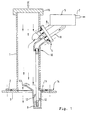
- a lubricating oil filling line 1 is connected to a flange 2 an area of an internal combustion engine 3 which can be fastened with the crankcase of the internal combustion engine 3 in connection stands. Through an opening in this area of an outer wall of the engine is the inside of the lubricating oil filling line 1 through the flange connection 14 with the crankcase in connection. At the top can be closed by a cover 15 Opening of the lubricating oil filling line 1 can Lubricating oil can be filled.
- An oil mist separator 5 is connected via a flange connection 4 with the lubricating oil filling line 1 in its upper area releasably connected.
- the oil mist separator is a particular one Cyclone separator.
- oil mist separator 5 passes through a Flange connection 4 interruptible crankcase ventilation line 6 the oil mist to be cleared of oil. The one freed from oil Venting air leaves the oil mist separator 5 a nozzle 7.
- the oil separated in the oil mist separator 5 is over a separable return oil line in the flange connection 4 8 led into the interior of the lubricating oil filling line 1.
- the overflow tank 9 is with the part of the internal combustion engine 3, on which the lubricating oil filling line 1 is fastened, also attached. This attachment is detachable and is in of the drawing in the area 11 indicated schematically.
- a detachable connection is indicated schematically in regions 12 between the overflow tank 9 and the lower separable Part of the return oil line 8.
- the opening of the overflow container 9 is at least in one Partial circumferential area 13 expanded funnel-shaped to thereby when filling the lubricating oil filler line 1 a compulsory one Ensure filling of the overflow tank 9.
- the vertical distance between the oil mist separator 5 and the bottom of the overflow tank 9 is to be designed such that due to a between the interior of the lubricating oil filling line 1 and the return oil drain chamber of the oil mist separator 5 existing pressure difference none for pressure equalization Oil rising in the return oil line 8 too in the worst operating conditions in the oil mist separator can penetrate. Of course, this must be done also the filling volume of the overflow container 9 accordingly be large.
- the modular component according to the invention consisting of the Lube oil filling line 1, the oil separator 5, the crankcase ventilation line 6, the return oil line 8 with an associated Overflow container 9 can not even with one Oil dipstick shown may be provided.
Landscapes
- Engineering & Computer Science (AREA)
- Mechanical Engineering (AREA)
- General Engineering & Computer Science (AREA)
- Lubrication Details And Ventilation Of Internal Combustion Engines (AREA)
Applications Claiming Priority (3)
| Application Number | Priority Date | Filing Date | Title |
|---|---|---|---|
| DE19704594 | 1997-02-07 | ||
| DE19704594A DE19704594A1 (de) | 1997-02-07 | 1997-02-07 | Schmieröleinfülleitung eines Verbrennungsmotors mit Ölnebelabscheider |
| PCT/DE1998/000050 WO1998035141A1 (de) | 1997-02-07 | 1998-01-03 | Schmieröleinfülleitung eines verbrennungsmotors mit ölnebelabscheider |
Publications (2)
| Publication Number | Publication Date |
|---|---|
| EP0931207A1 EP0931207A1 (de) | 1999-07-28 |
| EP0931207B1 true EP0931207B1 (de) | 2000-03-29 |
Family
ID=7819553
Family Applications (1)
| Application Number | Title | Priority Date | Filing Date |
|---|---|---|---|
| EP98905225A Expired - Lifetime EP0931207B1 (de) | 1997-02-07 | 1998-01-03 | Schmieröleinfülleitung eines verbrennungsmotors mit ölnebelabscheider |
Country Status (7)
| Country | Link |
|---|---|
| US (1) | US6089213A (enExample) |
| EP (1) | EP0931207B1 (enExample) |
| JP (1) | JP4037910B2 (enExample) |
| BR (1) | BR9807311A (enExample) |
| DE (2) | DE19704594A1 (enExample) |
| ES (1) | ES2145639T3 (enExample) |
| WO (1) | WO1998035141A1 (enExample) |
Cited By (1)
| Publication number | Priority date | Publication date | Assignee | Title |
|---|---|---|---|---|
| DE102012206885B4 (de) | 2011-05-09 | 2023-03-30 | Ford Global Technologies, Llc | Systeme zum Zurückleiten von aus Motorkurbelgehäusegasen abgeschiedenem Öl |
Families Citing this family (16)
| Publication number | Priority date | Publication date | Assignee | Title |
|---|---|---|---|---|
| DE19912271A1 (de) * | 1999-03-18 | 2000-09-28 | Hengst Walter Gmbh & Co Kg | Ölabscheider zur Entölung von Kurbelgehäuse-Entlüftungsgasen einer Brennkraftmaschine |
| DE19948163A1 (de) * | 1999-10-07 | 2001-04-12 | Volkswagen Ag | Vorrichtung für die Kurbelgehäuse/Zylinderkopf-Entlüftung eines Verbrennungsmotors |
| JP3971082B2 (ja) * | 2000-05-11 | 2007-09-05 | 本田技研工業株式会社 | 内燃機関用潤滑装置 |
| AT411091B (de) * | 2000-11-30 | 2003-09-25 | Kirchberger Roland Dipl Ing | Viertakt-verbrennungsmotor |
| FR2868468B1 (fr) * | 2004-04-06 | 2008-03-21 | Renault Sas | Dispositif de retour d huile formant siphon pour moteur a combustion interne |
| JP4517831B2 (ja) * | 2004-11-30 | 2010-08-04 | 株式会社豊田自動織機 | 内燃機関 |
| DE102008022818A1 (de) * | 2008-05-08 | 2009-11-12 | Hengst Gmbh & Co.Kg | Ölabscheider mit Siphon |
| US20130025564A1 (en) * | 2011-07-28 | 2013-01-31 | Electro-Motive Diesel, Inc. | Oil separator for crankcase ventilation |
| US9080478B2 (en) * | 2013-01-21 | 2015-07-14 | Ford Global Technologies, Llc | Oil separator |
| GB201409064D0 (en) * | 2014-05-21 | 2014-07-02 | Castrol Ltd | Method and apparatus |
| DE202015000384U1 (de) * | 2015-01-17 | 2016-04-20 | GM Global Technology Operations LLC (n. d. Ges. d. Staates Delaware) | Verschlusseinrichtung für einen Kraftfahrzeugmotor |
| JP7047434B2 (ja) * | 2018-02-13 | 2022-04-05 | いすゞ自動車株式会社 | オイル戻し構造 |
| FR3092360B1 (fr) * | 2019-02-05 | 2021-04-30 | Sogefi Filtration Spa | Dispositif séparateur doté d’au moins un cyclone et procédé, pour séparer l’huile des gaz de carter d’un moteur à combustion interne |
| DE102019004377A1 (de) * | 2019-06-19 | 2020-12-24 | Deutz Aktiengesellschaft | Ölrücklaufventil für ein Kurbelgehäuseentlüftungssystem |
| CN114251153B (zh) * | 2020-09-24 | 2023-03-10 | 北京汽车动力总成有限公司 | 一种曲通管路结构及车辆 |
| DE102023108722A1 (de) * | 2023-04-05 | 2024-10-10 | Bayerische Motoren Werke Aktiengesellschaft | Ölfangeinrichtung und Ölentnahmeanordnung zum Fangen von aus einer Verbrennungskraftmaschine herausgeschleudertem Öl |
Family Cites Families (10)
| Publication number | Priority date | Publication date | Assignee | Title |
|---|---|---|---|---|
| DE7507299U (de) * | 1975-07-10 | Audi Nsu Auto Union Ag | Gehäuse für eine Kraftmaschine | |
| US2354722A (en) * | 1940-06-12 | 1944-08-01 | Air Maze Corp | Crankcase oil separator |
| GB1495870A (en) * | 1976-02-04 | 1977-12-21 | Ford Motor Co | Crankcase breathers for internal combustion engines |
| US4169432A (en) * | 1977-03-31 | 1979-10-02 | Ford Motor Company | Integrated PCV valve and oil filler cap |
| US4401093A (en) * | 1982-06-09 | 1983-08-30 | Ford Motor Company | Oil fill/air breather cap with integral oil separator |
| US4768493A (en) * | 1984-04-27 | 1988-09-06 | Honda Giken Kogyo Kabushiki Kaisha | Blow-by gas heating system for internal combustion engines |
| DE3914759A1 (de) * | 1989-05-05 | 1990-11-08 | Mann & Hummel Filter | Einfuelloeffnung fuer das einfuellen von schmieroel in eine brennkraftmaschine |
| DE3938919C1 (en) * | 1989-11-24 | 1990-12-13 | Mercedes-Benz Aktiengesellschaft, 7000 Stuttgart, De | Oil separator for vent gases from engine crankcase - comprises housing contg. rotation-symmetrical filter through which vent gas flows outwards to cleaning space |
| DE4017074A1 (de) * | 1990-05-26 | 1991-11-28 | Mann & Hummel Filter | Druckregelventil fuer die kurbelgehaeuseentlueftung an einer brennkraftmaschine |
| DE9410668U1 (de) * | 1994-07-02 | 1994-08-18 | Filterwerk Mann + Hummel GmbH, 71638 Ludwigsburg | Kurbelgehäuse für Brennkraftmaschinen |
-
1997
- 1997-02-07 DE DE19704594A patent/DE19704594A1/de not_active Withdrawn
-
1998
- 1998-01-03 EP EP98905225A patent/EP0931207B1/de not_active Expired - Lifetime
- 1998-01-03 WO PCT/DE1998/000050 patent/WO1998035141A1/de not_active Ceased
- 1998-01-03 JP JP53350798A patent/JP4037910B2/ja not_active Expired - Fee Related
- 1998-01-03 DE DE59800110T patent/DE59800110D1/de not_active Expired - Lifetime
- 1998-01-03 BR BR9807311-7A patent/BR9807311A/pt not_active IP Right Cessation
- 1998-01-03 ES ES98905225T patent/ES2145639T3/es not_active Expired - Lifetime
- 1998-01-03 US US09/355,298 patent/US6089213A/en not_active Expired - Lifetime
Cited By (1)
| Publication number | Priority date | Publication date | Assignee | Title |
|---|---|---|---|---|
| DE102012206885B4 (de) | 2011-05-09 | 2023-03-30 | Ford Global Technologies, Llc | Systeme zum Zurückleiten von aus Motorkurbelgehäusegasen abgeschiedenem Öl |
Also Published As
| Publication number | Publication date |
|---|---|
| ES2145639T3 (es) | 2000-07-01 |
| US6089213A (en) | 2000-07-18 |
| EP0931207A1 (de) | 1999-07-28 |
| BR9807311A (pt) | 2000-05-02 |
| DE19704594A1 (de) | 1998-08-13 |
| JP4037910B2 (ja) | 2008-01-23 |
| DE59800110D1 (de) | 2000-05-04 |
| JP2001510524A (ja) | 2001-07-31 |
| WO1998035141A1 (de) | 1998-08-13 |
Similar Documents
| Publication | Publication Date | Title |
|---|---|---|
| EP0931207B1 (de) | Schmieröleinfülleitung eines verbrennungsmotors mit ölnebelabscheider | |
| DE102008008466B4 (de) | Fluidspeichervorrichtung und damit aususgestaltetes Getriebe | |
| DE102009001460B4 (de) | Ölbehälter | |
| DE19716085B4 (de) | Filter, insbesondere für Kraftstoffe von Verbrennungsmotoren | |
| EP0250734B1 (de) | Kühleinrichtung in einem flüssigkeitsgekühlten Kraftfahrzeug-Verbrennungsmotor | |
| DE112007001879T5 (de) | Schnellablaßfilter | |
| DE3036715C2 (de) | Schmierkreislauf mit Notschmierung für ein Gasturbinentriebwerk | |
| DE102005051263A1 (de) | Öltankanordnung mit trockenem Sumpf | |
| DE202010011973U1 (de) | Ölablassvorrichtung | |
| DE10310179B4 (de) | Ölauffangvorrichtung für eine Brennkraftmaschine, insbesondere für einen Boxermotor | |
| DE102015215788A1 (de) | Ölleitschale für ein Getriebe und Getriebe | |
| EP1860290A1 (de) | Ölwechseleinrichtung, Ölsammelgehäuse und Verfahren zum Ölwechseln | |
| EP1599659B1 (de) | Vorrichtung zur entschäumung von öl im schmiermittelkreislauf einer brennkraftmaschine | |
| DE4311470C2 (de) | Be- und Entlüftungseinrichtung eines Fahrzeug-Kraftstofftanks | |
| EP0815913B1 (de) | Filter | |
| EP0284727B1 (de) | Ölbehälter | |
| DE102004041110B4 (de) | Brennkraftmaschine und zugehörige Zylinderkopfhaube | |
| EP3382193B1 (de) | Kraftstofffilter zum filtern von kraftstoff in einem kraftfahrzeug und kraftfahrzeug mit einem solchen kraftstofffilter | |
| DE10110381B4 (de) | Vorrichtung zum Abtrennen von Verunreinigungen aus einem Schmieröl einer Brennkraftmaschine | |
| DE19838247A1 (de) | Ölnebelabscheider | |
| AT399712B (de) | Vorrichtung zum entnehmen von leichtflüssigkeiten aus leichtflüssigkeitsabscheidern | |
| DE9401148U1 (de) | Abscheider für Leichtflüssigkeiten | |
| DE102019105414A1 (de) | Flüssigkeitsfilter | |
| DE102024102847A1 (de) | Fluidausgleichsbehälter | |
| DE2061597A1 (de) | Vorrichtung zum Entschäumen von Schmiermitteln, vorzugsweise Öl |
Legal Events
| Date | Code | Title | Description |
|---|---|---|---|
| PUAI | Public reference made under article 153(3) epc to a published international application that has entered the european phase |
Free format text: ORIGINAL CODE: 0009012 |
|
| 17P | Request for examination filed |
Effective date: 19990331 |
|
| AK | Designated contracting states |
Kind code of ref document: A1 Designated state(s): DE ES FR GB |
|
| GRAG | Despatch of communication of intention to grant |
Free format text: ORIGINAL CODE: EPIDOS AGRA |
|
| GRAG | Despatch of communication of intention to grant |
Free format text: ORIGINAL CODE: EPIDOS AGRA |
|
| GRAH | Despatch of communication of intention to grant a patent |
Free format text: ORIGINAL CODE: EPIDOS IGRA |
|
| 17Q | First examination report despatched |
Effective date: 19991013 |
|
| RAP1 | Party data changed (applicant data changed or rights of an application transferred) |
Owner name: MAHLE FILTERSYSTEME GMBH |
|
| GRAH | Despatch of communication of intention to grant a patent |
Free format text: ORIGINAL CODE: EPIDOS IGRA |
|
| GRAA | (expected) grant |
Free format text: ORIGINAL CODE: 0009210 |
|
| AK | Designated contracting states |
Kind code of ref document: B1 Designated state(s): DE ES FR GB |
|
| REF | Corresponds to: |
Ref document number: 59800110 Country of ref document: DE Date of ref document: 20000504 |
|
| GBT | Gb: translation of ep patent filed (gb section 77(6)(a)/1977) |
Effective date: 20000417 |
|
| REG | Reference to a national code |
Ref country code: ES Ref legal event code: FG2A Ref document number: 2145639 Country of ref document: ES Kind code of ref document: T3 |
|
| ET | Fr: translation filed | ||
| PLBE | No opposition filed within time limit |
Free format text: ORIGINAL CODE: 0009261 |
|
| STAA | Information on the status of an ep patent application or granted ep patent |
Free format text: STATUS: NO OPPOSITION FILED WITHIN TIME LIMIT |
|
| 26N | No opposition filed | ||
| REG | Reference to a national code |
Ref country code: GB Ref legal event code: IF02 |
|
| REG | Reference to a national code |
Ref country code: FR Ref legal event code: PLFP Year of fee payment: 19 |
|
| PGFP | Annual fee paid to national office [announced via postgrant information from national office to epo] |
Ref country code: ES Payment date: 20160223 Year of fee payment: 19 Ref country code: DE Payment date: 20160331 Year of fee payment: 19 |
|
| PGFP | Annual fee paid to national office [announced via postgrant information from national office to epo] |
Ref country code: GB Payment date: 20160129 Year of fee payment: 19 Ref country code: FR Payment date: 20160129 Year of fee payment: 19 |
|
| REG | Reference to a national code |
Ref country code: DE Ref legal event code: R119 Ref document number: 59800110 Country of ref document: DE |
|
| GBPC | Gb: european patent ceased through non-payment of renewal fee |
Effective date: 20170103 |
|
| REG | Reference to a national code |
Ref country code: FR Ref legal event code: ST Effective date: 20170929 |
|
| PG25 | Lapsed in a contracting state [announced via postgrant information from national office to epo] |
Ref country code: FR Free format text: LAPSE BECAUSE OF NON-PAYMENT OF DUE FEES Effective date: 20170131 |
|
| PG25 | Lapsed in a contracting state [announced via postgrant information from national office to epo] |
Ref country code: GB Free format text: LAPSE BECAUSE OF NON-PAYMENT OF DUE FEES Effective date: 20170103 Ref country code: DE Free format text: LAPSE BECAUSE OF NON-PAYMENT OF DUE FEES Effective date: 20170801 |
|
| REG | Reference to a national code |
Ref country code: ES Ref legal event code: FD2A Effective date: 20180507 |
|
| PG25 | Lapsed in a contracting state [announced via postgrant information from national office to epo] |
Ref country code: ES Free format text: LAPSE BECAUSE OF NON-PAYMENT OF DUE FEES Effective date: 20170104 |