EP0284727B1 - Ölbehälter - Google Patents
Ölbehälter Download PDFInfo
- Publication number
- EP0284727B1 EP0284727B1 EP88101455A EP88101455A EP0284727B1 EP 0284727 B1 EP0284727 B1 EP 0284727B1 EP 88101455 A EP88101455 A EP 88101455A EP 88101455 A EP88101455 A EP 88101455A EP 0284727 B1 EP0284727 B1 EP 0284727B1
- Authority
- EP
- European Patent Office
- Prior art keywords
- oil reservoir
- oil
- immersion tube
- tube
- return line
- Prior art date
- Legal status (The legal status is an assumption and is not a legal conclusion. Google has not performed a legal analysis and makes no representation as to the accuracy of the status listed.)
- Expired - Lifetime
Links
- 238000007654 immersion Methods 0.000 claims description 15
- 229910000831 Steel Inorganic materials 0.000 claims description 3
- 238000002485 combustion reaction Methods 0.000 claims description 3
- 238000005461 lubrication Methods 0.000 claims description 3
- 239000010959 steel Substances 0.000 claims description 3
- 210000002268 wool Anatomy 0.000 claims description 3
- 238000009423 ventilation Methods 0.000 description 3
- 230000000694 effects Effects 0.000 description 2
- 230000003319 supportive effect Effects 0.000 description 1
Images


Classifications
-
- F—MECHANICAL ENGINEERING; LIGHTING; HEATING; WEAPONS; BLASTING
- F16—ENGINEERING ELEMENTS AND UNITS; GENERAL MEASURES FOR PRODUCING AND MAINTAINING EFFECTIVE FUNCTIONING OF MACHINES OR INSTALLATIONS; THERMAL INSULATION IN GENERAL
- F16N—LUBRICATING
- F16N19/00—Lubricant containers for use in lubricators or lubrication systems
-
- F—MECHANICAL ENGINEERING; LIGHTING; HEATING; WEAPONS; BLASTING
- F01—MACHINES OR ENGINES IN GENERAL; ENGINE PLANTS IN GENERAL; STEAM ENGINES
- F01M—LUBRICATING OF MACHINES OR ENGINES IN GENERAL; LUBRICATING INTERNAL COMBUSTION ENGINES; CRANKCASE VENTILATING
- F01M1/00—Pressure lubrication
- F01M1/10—Lubricating systems characterised by the provision therein of lubricant venting or purifying means, e.g. of filters
-
- F—MECHANICAL ENGINEERING; LIGHTING; HEATING; WEAPONS; BLASTING
- F01—MACHINES OR ENGINES IN GENERAL; ENGINE PLANTS IN GENERAL; STEAM ENGINES
- F01M—LUBRICATING OF MACHINES OR ENGINES IN GENERAL; LUBRICATING INTERNAL COMBUSTION ENGINES; CRANKCASE VENTILATING
- F01M1/00—Pressure lubrication
- F01M1/12—Closed-circuit lubricating systems not provided for in groups F01M1/02 - F01M1/10
- F01M2001/126—Dry-sumps
-
- F—MECHANICAL ENGINEERING; LIGHTING; HEATING; WEAPONS; BLASTING
- F01—MACHINES OR ENGINES IN GENERAL; ENGINE PLANTS IN GENERAL; STEAM ENGINES
- F01M—LUBRICATING OF MACHINES OR ENGINES IN GENERAL; LUBRICATING INTERNAL COMBUSTION ENGINES; CRANKCASE VENTILATING
- F01M11/00—Component parts, details or accessories, not provided for in, or of interest apart from, groups F01M1/00 - F01M9/00
- F01M11/0004—Oilsumps
- F01M2011/0083—Dry sumps
Definitions
- the invention relates to an oil container according to the preamble of claim 1.
- the object of the invention is to provide an oil container with an arrangement of an oil return line, which ensures a low-noise inlet of the oil into the container.
- the oil flow when it enters the immersion tube is guided against the wall as long as possible until it has flowed into the medium of the oil container. This causes the noise to be reduced, and the immersion tube itself has a noise-reducing effect.
- a supportive measure for noise reduction is also that the dip tube is elastically mounted to the container and can also be double-walled. The remaining space between the walls of the dip tube can either be filled with steel wool or an agent with the same effect, or a cavity remains.
- the return line can be made separately and the parts can be connected to one another via an elastic hose, so that the dip tube is kept virtually vibration-decoupled from the oil container.
- Such a design of the line is also possible in the case of an immersion pipe which is fixedly arranged in the oil container.
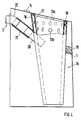
- an oil container 1 In dry sump lubrication for an internal combustion engine in a motor vehicle, an oil container 1 has a specific oil level 2, above which a return line 3 opens. Oil is supplied to the drive unit via a suction line 4 arranged in the oil, the opening 5 of which is arranged near the tank bottom 6.
- the return line 3 opens into an immersion tube 7 which is connected to an upper container wall 8 and is closed at the end thereof. It extends approximately vertically into the container space 9 and dips with its lower end 10 into the medium, so that an opening 11 of the dip tube lies below the oil level 2.
- the dip tube 7 has a cylindrical shape (not shown) or preferably a funnel shape (FIG. 1).
- the dip tube 7 is provided above a junction 12 of the return line 3 with a plurality of ventilation openings 13, which establish a direct connection to the container space 9.
- an air outlet opening 14 is provided adjacent to the ventilation openings 13, via which the outflowing air portions of the oil are discharged, as the arrows show in more detail.
- the return line 3 is preferably shown at an angle ⁇ to a horizontal plane X-X, so that an oblique alignment with the oil level is produced. As shown in Fig. 2, the line 3 runs approximately tangentially to the inner tube wall 15, so that an oil flow is applied to the inner wall 15 and runs in a spiral in the dip tube until it flows into the existing medium of the container 1 below the oil level 2.
- the dip tube 7 is funnel-shaped and is designed with its small opening 11 to be immersed in the medium.
- the dip tube 7a shown in FIG. 4 has a double wall 16 u. 17, which either have a cavity between them, but which can also be filled with steel wool or a similar agent.
- the walls 16 and 17 each have ventilation holes 13a, 13b, which are arranged offset in height from one another.
- An attachment of the dip tube 7; 7a on the container 1 can take place via elastic elements 18, 19 which act to isolate structure-borne noise.
- the return line 3 can between the with the dip tube 7; 7a connected first line part 20 and the second line part 22 connected to the container 1 via an elastic rubber hose 21.
Landscapes
- Engineering & Computer Science (AREA)
- General Engineering & Computer Science (AREA)
- Mechanical Engineering (AREA)
- Lubrication Details And Ventilation Of Internal Combustion Engines (AREA)
- Feeding And Controlling Fuel (AREA)
- Lubrication Of Internal Combustion Engines (AREA)
Description
- Die Erfindung bezieht sich auf einen Ölbehälter nach dem Oberbegriff des Anspruchs 1.
- Bei einer Trockensumpfschmierung für einen Motor eines Kraftfahrzeugs ist zwangsläufig die Ölansaugpumpe für den Ölkreislauf zum Ölbehälter überdimensioniert. Es gelangt somit ein hoher Luftanteil in den Ölrücklauf, was dazu führt, daß das Öl nicht mehr gleichmäßig fließt und ein sogenanntes Plätschern beim Austreten des mit Luftanteilen angereicherten Ölstromes aus der Rücklaufleitung in den Behälter entsteht.
- Aus der DE-A 19 03 295 ist ein Öl-Vorratsbehälter in einer Brennkraftmaschine bekannt, in den eine zylindrische nach unten offene Glocke eingesetzt ist, in die eine Öl-Rücklaufleitung einmündet. Die Glocke taucht mit ihrem unteren Rohrende in das Medium ein und ist mit ihrem oberen Rohrende beabstandet zum Behälter angeordnet und mit einer zentralen Öffnung versehen.
- Die Aufgabe der Erfindung besteht darin, einen Ölbehälter mit einer Anordnung einer Ölrücklaufleitung zu schaffen, die einen geräuscharmen Einlauf des Öls in den Behälter gewährleistet.
- Durch die Erfindung wird erreicht, daß der Ölstrom beim Eintreten in das Tauchrohr möglichst an dessen Wandung solange anliegend geführt wird, bis es in das Medium des Ölbehälters eingeflossen ist. Dies bewirkt eine Absenkung des Geräusches, wobei das Tauchrohr an sich schon geräuschmindernd wirkt. Eine unterstützende Maßnahme zur Geräuschreduzierung ist auch, daß das Tauchrohr zum Behälter elastisch gelagert ist und darüber hinaus doppelwandig ausgeführt sein kann. Der verbleibende Raum zwischen den Wandungen des Tauchrohres kann entweder mit Stahlwolle oder einem gleichwirkenden Mittel ausgefüllt sein oder es verbleibt ein Hohlraum.
- Bei der Lagerung des Tauchrohres über die elastischen Elemente kann die Rücklaufleitung getrennt ausgeführt und die Teile über einen elastischen Schlauch miteinander verbunden sein, so daß das Tauchrohr zum Ölbehälter nahezu schwingungsentkoppelt gehalten ist. Eine solche Ausbildung der Leitung ist auch bei einem fest im Ölbehälter angeordneten Tauchrohr möglich.
- Ein Ausführungsbeispiel der Erfindung ist in der Zeichnung dargestellt und wird im folgenden näher beschrieben.
- Es zeigen:
- Fig. 1
- einen Ölbehälter mit einem Tauchrohr teilweise im Schnitt,
- Fig. 2
- einen Schnitt durch das Tauchrohr gemäß der Linie II-II der Fig. 1,
- Fig. 3
- eine Ansicht auf den Ölbehälter in Pfeilrichtung Z gesehen und
- Fig. 4
- eine weitere Ausführungsform eines elastisch gelagerten Tauchrohres im Ölbehälter mit einer abgekoppelten Öl-Rücklaufleitung.
- Bei einer Trockensumpfschmierung für eine Brennkraftmaschine in einem Kraftfahrzeug weist ein Ölbehälter 1 ein bestimmtes Ölniveau 2 auf, über dem eine Rücklaufleitung 3 einmündet. Über eine im Öl angeordnete Absaugleitung 4, deren Öffnung 5 nahe dem Behälterboden 6 angeordnet ist, wird dem Antriebsaggregat Öl zugeführt.
- Die Rücklaufleitung 3 mündet in ein Tauchrohr 7 ein, das mit einer oberen Behälterwand 8 verbunden und über diese stirnseitig abgeschlossen ist. Es erstreckt sich etwa vertikal in den Behälterraum 9 und taucht mit seinem unteren Ende 10 in das Medium ein, so daß eine Öffnung 11 des Tauchrohres unterhalb des Ölniveaus 2 liegt. Das Tauchrohr 7 weist eine zylindrische Form (nicht gezeigt) oder vorzugsweise eine Trichterform auf (Fig. 1).
- Das Tauchrohr 7 ist oberhalb einer Einmündung 12 der Rücklaufleitung 3 mit mehreren Entlüftungsöffnungen 13 versehen, die eine direkte Verbindung zum Behälterraum 9 herstellen. Zu diesem ist benachbart der Entlüftungsöffnungen 13 eine Luftauslaßöffnung 14 vorgesehen, über welche die abströmenden Luftanteile des Öls abgeführt werden, wie die Pfeile näher zeigen.
- Die Rücklaufleitung 3 ist vorzugsweise unter einem Winkel α zu einer horizontalen Ebene X-X dargestellt, so daß eine schräge Ausrichtung zum Ölniveau hergestellt wird. Wie in Fig. 2 gezeigt ist, verläuft die Leitung 3 annähernd tangential zur Rohrinnenwand 15, so daß ein Ölstrom sich an die Innenwand 15 anlegt und spiralförmig im Tauchrohr bis zum Einfließen in das vorhandene Medium des Behälters 1 unterhalb des Ölniveaus 2 abläuft.
- Nach der Ausführung gemäß Fig. 1 ist das Tauchrohr 7 trichterförmig ausgebildet und mit seiner kleinen Öffnung 11 ins Medium eintauchend ausgeführt.
- Das Tauchrohr 7a gemäß Fig. 4, weist eine doppelte Wandung 16 u. 17 auf, die zwischen sich entweder einen Hohlraum aufweisen, der aber auch mit Stahlwolle oder einem gleichwirkenden Mittel ausgefüllt sein kann. Die Wandungen 16 und 17 weisen jeweils Entlüftungslöcher 13a, 13b auf, die höhenversetzt zueinander angeordnet sind.
- Eine Befestigung des Tauchrohres 7; 7a am Behälter 1 kann über elastische Elemente 18, 19 erfolgen, die körperschallisolierend wirken.
- Die Rücklaufleitung 3 kann zwischen dem mit dem Tauchrohr 7; 7a verbundenen ersten Leitungsteil 20 und dem mit dem Behälter 1 verbundenen zweiten Leitungsteil 22 über einen elastischen Gummischlauch 21 verbunden sein.
Claims (7)
- Ölbehälter (1) in einer Brennkraftmaschine mit Trockensumpfschmierung, der eine Öl-Rücklaufleitung (3) und eine mit einer Pumpe des Kreislaufs verbundene Öl-Absaugleitung (4) aufweist und die Rücklaufleitung (3) in ein Tauchrohr (7; 7a) des Behälters (1) einmündet, das mit seinem eine Öffnung (11) aufweisenden unteren Rohrende (10) in das Medium eintaucht, dadurch gekennzeichnet, daß das abgekehrte obere Rohrende (10a) abgeschlossen ist und daß oberhalb der Einmündung (12) der Rücklaufleitung (3) in das Tauchrohr (7; 7a) Entlüftungsöffnungen (13; 13a; 13b) angeordnet sind, die benachbart zu einer Luftauslaßöffnung (14) im Ölbehälter (1) angeordnet sind.
- Ölbehälter nach Anspruch 1, dadurch gekennzeichnet, daß die Rücklaufleitung (3) unter einem Winkel (α) zu einer horizontalen Ebene (X-X) geneigt, in das etwa vertikal angeordnete Tauchrohr (7; 7a) einmündet, wobei es annähernd tangential zur Rohrinnenwand (15) ausgerichtet ist.
- Ölbehälter nach den Ansprüchen 1 oder 2, dadurch gekennzeichnet, daß das Tauchrohr (7; 7a) trichterförmig ausgebildet ist und mit seiner kleinen Öffnung (11) dem Medium zugerichtet ist.
- Ölbehälter nach einem oder mehreren der vorhergehenden Ansprüche, dadurch gekennzeichnet, daß das Tauchrohr (7) mit seinem oberen Rohrende (10a) an einer oberen Behälterwand (8) befestigt und von dieser verschlossen ist.
- Ölbehälter nach Anspruch 1, dadurch gekennzeichnet, daß das Tauchrohr (7a) doppelwandig ausgeführt und zwischen den Wandungen (16 und 17) Stahlwolle angeordnet ist.
- Ölbehälter nach Anspruch 5, dadurch gekennzeichnet, daß die Entlüftungslöcher (13a) in der Außenwandung (16) höhenversetzt zu den Entlüftungslöchern (13b) in der Innenwandung (17) angeordnet sind.
- Ölbehälter nach einem oder mehreren der vorhergehenden Ansprüche, dadurch gekennzeichnet, daß das Tauchrohr (7; 7a) obenseitig abgeschlossen ist und zu den Wandungen des Ölbehälters (1) über mehrere elastische Elemente (18, 19) abgestützt wird und daß die Rücklaufleitung (3) einen elastischen Verbindungsschlauch (21) umfaßt, der ein mit dem Tauchrohr (7; 7a) verbundenes erstes rohrfestes Leitungsteil (20) mit einem zweiten behälterfesten Leitungsteil (22) verbindet.
Applications Claiming Priority (2)
| Application Number | Priority Date | Filing Date | Title |
|---|---|---|---|
| DE3711000 | 1987-04-01 | ||
| DE19873711000 DE3711000A1 (de) | 1987-04-01 | 1987-04-01 | Oelbehaelter |
Publications (3)
| Publication Number | Publication Date |
|---|---|
| EP0284727A2 EP0284727A2 (de) | 1988-10-05 |
| EP0284727A3 EP0284727A3 (en) | 1989-06-07 |
| EP0284727B1 true EP0284727B1 (de) | 1992-06-24 |
Family
ID=6324646
Family Applications (1)
| Application Number | Title | Priority Date | Filing Date |
|---|---|---|---|
| EP88101455A Expired - Lifetime EP0284727B1 (de) | 1987-04-01 | 1988-02-02 | Ölbehälter |
Country Status (3)
| Country | Link |
|---|---|
| EP (1) | EP0284727B1 (de) |
| DE (2) | DE3711000A1 (de) |
| ES (1) | ES2033347T3 (de) |
Families Citing this family (6)
| Publication number | Priority date | Publication date | Assignee | Title |
|---|---|---|---|---|
| SE503941C2 (sv) * | 1994-12-28 | 1996-10-07 | Tetra Laval Holdings & Finance | Anslutningsanordning för ett smörjsystem samt en pumpanordning med en sådan anslutningsanordning |
| GB0128958D0 (en) * | 2001-12-03 | 2002-01-23 | Mclaren Cars Nv | Improvements in or relating to oil tanks for dry sump engines |
| US7918316B2 (en) | 2002-04-30 | 2011-04-05 | Bayerische Motoren Werke Aktiengesellschaft | Separating device in a motor vehicle oil circuit |
| DE10219279B4 (de) * | 2002-04-30 | 2005-02-24 | Bayerische Motoren Werke Ag | Trenneinrichtung in einem Ölkreislauf eines Kraftfahrzeugs |
| DE102006055760B4 (de) * | 2006-11-25 | 2013-12-19 | Audi Ag | Schmiermitteltank mit einem Gasabscheider |
| DE102011104017A1 (de) * | 2011-06-11 | 2012-12-13 | Audi Ag | Behälter für ein Betriebsmedium eines Kraftwagens |
Family Cites Families (5)
| Publication number | Priority date | Publication date | Assignee | Title |
|---|---|---|---|---|
| US2432130A (en) * | 1942-07-04 | 1947-12-09 | Sharpies Corp | Oil circulating and feeding system |
| US2983331A (en) * | 1957-07-08 | 1961-05-09 | North American Aviation Inc | Inverted flight reservoir |
| DE2005594A1 (de) * | 1969-01-23 | 1971-08-19 | Dr Ing h c F Porsche KG, 7000 Stuttgart Zuffenhausen | Vorrichtung zum Entschäumen des Schmiermittels von Brennkraftmaschinen |
| DE1903295A1 (de) * | 1969-01-23 | 1970-08-06 | Porsche Kg | Vorrichtung zum Entschaeumen des Schmiermittels von Brennkraftmaschinen |
| FR2485630A1 (fr) * | 1980-06-30 | 1981-12-31 | Snecma | Reservoir a suspension antivibratoire |
-
1987
- 1987-04-01 DE DE19873711000 patent/DE3711000A1/de not_active Withdrawn
-
1988
- 1988-02-02 DE DE8888101455T patent/DE3872285D1/de not_active Expired - Lifetime
- 1988-02-02 ES ES198888101455T patent/ES2033347T3/es not_active Expired - Lifetime
- 1988-02-02 EP EP88101455A patent/EP0284727B1/de not_active Expired - Lifetime
Also Published As
| Publication number | Publication date |
|---|---|
| ES2033347T3 (es) | 1993-03-16 |
| DE3872285D1 (de) | 1992-07-30 |
| EP0284727A3 (en) | 1989-06-07 |
| DE3711000A1 (de) | 1988-10-20 |
| EP0284727A2 (de) | 1988-10-05 |
Similar Documents
| Publication | Publication Date | Title |
|---|---|---|
| DE102008060412B4 (de) | Verbrennungsmotor | |
| EP2221097B1 (de) | Filtereinrichtung zur Kohlenwasserstoffadsorption | |
| DE69107575T2 (de) | Windschutzscheibenwaschpumpe. | |
| EP1591633A2 (de) | Ölwannenanordnung für eine Maschine und/oder ein Getriebe | |
| DE19833974A1 (de) | Filterelement für Ölwanne und Kombination aus Filterelement und Ölwanne | |
| DE10333185A1 (de) | Flacher Kraftstofffilter | |
| EP0931207B1 (de) | Schmieröleinfülleitung eines verbrennungsmotors mit ölnebelabscheider | |
| EP0284727B1 (de) | Ölbehälter | |
| DE10315237A1 (de) | Reservoireinheit | |
| DE10315236A1 (de) | Reservoireinheit | |
| DE202005003383U1 (de) | Öl-Vorratsbehälter | |
| DE102008060409B4 (de) | Verbrennungsmotor | |
| DE69101410T2 (de) | Reinigungsflüssigkeitsdruckpumpe für kraftfahrzeuge. | |
| DE3321751C2 (de) | ||
| DE19959976A1 (de) | Pumpe | |
| DE3021388C2 (de) | Wasserablauftülle, insbesondere für Hohlräume in Kraftwagenaufbauten | |
| DE102017008812A1 (de) | Filtervorrichtung | |
| DE10151385A1 (de) | Modulare Vorrichtung zur Reinigung der Windschutzscheibe eines Kraftfahrzeuges | |
| DE3201946C2 (de) | Vorrichtung zum Absaugen von Farbnebeln aus Farbspritzräumen | |
| DE10356945B4 (de) | Halterung eines Kühlers | |
| DE202007006961U1 (de) | Brennkraftmaschine, insbesondere für ein Kraftfahrzeug | |
| DE2852416A1 (de) | Fluessigkeitssystem mit zusatztank und mehreren ausgleichsleitungen | |
| DE3534576C2 (de) | ||
| DE29711805U1 (de) | Sandstreueinrichtung für Schienenfahrzeuge | |
| DE3105955A1 (de) | Motor-kompressor-baueinheit fuer kuehlschraenke |
Legal Events
| Date | Code | Title | Description |
|---|---|---|---|
| PUAI | Public reference made under article 153(3) epc to a published international application that has entered the european phase |
Free format text: ORIGINAL CODE: 0009012 |
|
| AK | Designated contracting states |
Kind code of ref document: A2 Designated state(s): DE ES FR GB IT SE |
|
| PUAL | Search report despatched |
Free format text: ORIGINAL CODE: 0009013 |
|
| AK | Designated contracting states |
Kind code of ref document: A3 Designated state(s): DE ES FR GB IT SE |
|
| 17P | Request for examination filed |
Effective date: 19891006 |
|
| 17Q | First examination report despatched |
Effective date: 19910618 |
|
| GRAA | (expected) grant |
Free format text: ORIGINAL CODE: 0009210 |
|
| AK | Designated contracting states |
Kind code of ref document: B1 Designated state(s): DE ES FR GB IT SE |
|
| ITF | It: translation for a ep patent filed | ||
| REF | Corresponds to: |
Ref document number: 3872285 Country of ref document: DE Date of ref document: 19920730 |
|
| GBT | Gb: translation of ep patent filed (gb section 77(6)(a)/1977) | ||
| ET | Fr: translation filed | ||
| PGFP | Annual fee paid to national office [announced via postgrant information from national office to epo] |
Ref country code: SE Payment date: 19930205 Year of fee payment: 6 |
|
| PGFP | Annual fee paid to national office [announced via postgrant information from national office to epo] |
Ref country code: ES Payment date: 19930219 Year of fee payment: 6 |
|
| REG | Reference to a national code |
Ref country code: ES Ref legal event code: FG2A Ref document number: 2033347 Country of ref document: ES Kind code of ref document: T3 |
|
| PLBE | No opposition filed within time limit |
Free format text: ORIGINAL CODE: 0009261 |
|
| STAA | Information on the status of an ep patent application or granted ep patent |
Free format text: STATUS: NO OPPOSITION FILED WITHIN TIME LIMIT |
|
| 26N | No opposition filed | ||
| PG25 | Lapsed in a contracting state [announced via postgrant information from national office to epo] |
Ref country code: SE Effective date: 19940203 Ref country code: ES Free format text: LAPSE BECAUSE OF NON-PAYMENT OF DUE FEES Effective date: 19940203 |
|
| PGFP | Annual fee paid to national office [announced via postgrant information from national office to epo] |
Ref country code: GB Payment date: 19940208 Year of fee payment: 7 |
|
| PGFP | Annual fee paid to national office [announced via postgrant information from national office to epo] |
Ref country code: FR Payment date: 19940225 Year of fee payment: 7 |
|
| PGFP | Annual fee paid to national office [announced via postgrant information from national office to epo] |
Ref country code: DE Payment date: 19940301 Year of fee payment: 7 |
|
| EUG | Se: european patent has lapsed |
Ref document number: 88101455.9 Effective date: 19940910 |
|
| PG25 | Lapsed in a contracting state [announced via postgrant information from national office to epo] |
Ref country code: GB Effective date: 19950202 |
|
| GBPC | Gb: european patent ceased through non-payment of renewal fee |
Effective date: 19950202 |
|
| PG25 | Lapsed in a contracting state [announced via postgrant information from national office to epo] |
Ref country code: FR Effective date: 19951031 |
|
| PG25 | Lapsed in a contracting state [announced via postgrant information from national office to epo] |
Ref country code: DE Effective date: 19951101 |
|
| REG | Reference to a national code |
Ref country code: FR Ref legal event code: ST |
|
| REG | Reference to a national code |
Ref country code: ES Ref legal event code: FD2A Effective date: 19990301 |
|
| PG25 | Lapsed in a contracting state [announced via postgrant information from national office to epo] |
Ref country code: IT Free format text: LAPSE BECAUSE OF NON-PAYMENT OF DUE FEES;WARNING: LAPSES OF ITALIAN PATENTS WITH EFFECTIVE DATE BEFORE 2007 MAY HAVE OCCURRED AT ANY TIME BEFORE 2007. THE CORRECT EFFECTIVE DATE MAY BE DIFFERENT FROM THE ONE RECORDED. Effective date: 20050202 |