EP0930472A2 - Querstromlüfter - Google Patents
Querstromlüfter Download PDFInfo
- Publication number
- EP0930472A2 EP0930472A2 EP98309350A EP98309350A EP0930472A2 EP 0930472 A2 EP0930472 A2 EP 0930472A2 EP 98309350 A EP98309350 A EP 98309350A EP 98309350 A EP98309350 A EP 98309350A EP 0930472 A2 EP0930472 A2 EP 0930472A2
- Authority
- EP
- European Patent Office
- Prior art keywords
- outlet
- segment
- volute
- air
- center
- Prior art date
- Legal status (The legal status is an assumption and is not a legal conclusion. Google has not performed a legal analysis and makes no representation as to the accuracy of the status listed.)
- Granted
Links
Images


Classifications
-
- F—MECHANICAL ENGINEERING; LIGHTING; HEATING; WEAPONS; BLASTING
- F04—POSITIVE - DISPLACEMENT MACHINES FOR LIQUIDS; PUMPS FOR LIQUIDS OR ELASTIC FLUIDS
- F04D—NON-POSITIVE-DISPLACEMENT PUMPS
- F04D17/00—Radial-flow pumps, e.g. centrifugal pumps; Helico-centrifugal pumps
- F04D17/02—Radial-flow pumps, e.g. centrifugal pumps; Helico-centrifugal pumps having non-centrifugal stages, e.g. centripetal
- F04D17/04—Radial-flow pumps, e.g. centrifugal pumps; Helico-centrifugal pumps having non-centrifugal stages, e.g. centripetal of transverse-flow type
-
- F—MECHANICAL ENGINEERING; LIGHTING; HEATING; WEAPONS; BLASTING
- F24—HEATING; RANGES; VENTILATING
- F24F—AIR-CONDITIONING; AIR-HUMIDIFICATION; VENTILATION; USE OF AIR CURRENTS FOR SCREENING
- F24F1/00—Room units for air-conditioning, e.g. separate or self-contained units or units receiving primary air from a central station
- F24F1/0007—Indoor units, e.g. fan coil units
- F24F1/0018—Indoor units, e.g. fan coil units characterised by fans
- F24F1/0025—Cross-flow or tangential fans
-
- F—MECHANICAL ENGINEERING; LIGHTING; HEATING; WEAPONS; BLASTING
- F24—HEATING; RANGES; VENTILATING
- F24F—AIR-CONDITIONING; AIR-HUMIDIFICATION; VENTILATION; USE OF AIR CURRENTS FOR SCREENING
- F24F1/00—Room units for air-conditioning, e.g. separate or self-contained units or units receiving primary air from a central station
- F24F1/0007—Indoor units, e.g. fan coil units
- F24F1/0043—Indoor units, e.g. fan coil units characterised by mounting arrangements
- F24F1/0057—Indoor units, e.g. fan coil units characterised by mounting arrangements mounted in or on a wall
-
- F—MECHANICAL ENGINEERING; LIGHTING; HEATING; WEAPONS; BLASTING
- F24—HEATING; RANGES; VENTILATING
- F24F—AIR-CONDITIONING; AIR-HUMIDIFICATION; VENTILATION; USE OF AIR CURRENTS FOR SCREENING
- F24F1/00—Room units for air-conditioning, e.g. separate or self-contained units or units receiving primary air from a central station
- F24F1/02—Self-contained room units for air-conditioning, i.e. with all apparatus for treatment installed in a common casing
- F24F1/032—Self-contained room units for air-conditioning, i.e. with all apparatus for treatment installed in a common casing characterised by heat exchangers
- F24F1/0325—Self-contained room units for air-conditioning, i.e. with all apparatus for treatment installed in a common casing characterised by heat exchangers by the shape of the heat exchangers or of parts thereof, e.g. of their fins
-
- F—MECHANICAL ENGINEERING; LIGHTING; HEATING; WEAPONS; BLASTING
- F24—HEATING; RANGES; VENTILATING
- F24F—AIR-CONDITIONING; AIR-HUMIDIFICATION; VENTILATION; USE OF AIR CURRENTS FOR SCREENING
- F24F1/00—Room units for air-conditioning, e.g. separate or self-contained units or units receiving primary air from a central station
- F24F1/02—Self-contained room units for air-conditioning, i.e. with all apparatus for treatment installed in a common casing
- F24F1/0328—Self-contained room units for air-conditioning, i.e. with all apparatus for treatment installed in a common casing with means for purifying supplied air
Definitions
- the present invention relates to a cross flow fan provided as a blowing means for such as an air conditioner.
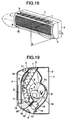
- Figs. 18 to 22 are diagrams illustrating examples of air conditioners in which cross flow fans 8 are mounted.
- Fig. 18 is a perspective view of a main body 1 of an air conditioner in which an upper air inlet grille 5 is not disposed on the rear surface side of a round starting point F 0 of a scroll casing 10
- Fig. 19 is a cross-sectional view, taken along a plane X in the direction of arrow L, of the main body 1 of the air conditioner in Fig. 18.
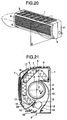
- Fig. 20 is a perspective view of the main body 1 of the air conditioner in which the upper air inlet grille 5 is disposed on the rear surface side of the round starting point F 0 of the scroll casing 10
- Fig. 21 is a cross-sectional view, taken along the plane X in the direction of arrow L, of the main body 1 of the air conditioner in Fig. 20.
- Fig. 22 is a diagram illustrating the flow of air in Fig. 21.
- the main body 1 of the air conditioner forms a casing which is comprised of a housing 2, which is located on the rear surface side of main body 1 of the air conditioner, as well as a panel 3 having a rotatably openable and detachable front air inlet grille 4 and the upper air inlet grille 5. Further, an air outlet 6 is formed by the housing 2 and the panel 3.
- reference numeral 7 denotes a heat exchanger which is bent in a chevron shape which is disposed on the front surface side of main body 1 of the air conditioner with respect to the round starting point F 0 , which is a starting point of the scroll casing 10.
- Numeral 19 denotes a drain pan for receiving drain water produced as air is condensed by the heat exchanger 7.
- Numeral 17 denotes a dust removing filter for removing dust in the air sucked into the main body 1 of the air conditioner.
- Numeral 18 denotes an air cleaning filter for cleaning air by means of activated carbon.
- a section of the housing 2 which extends from its portion close to the rear surface portion to its lower portion is formed by the scroll casing 10 and an air-outlet lower guide 12 continuing and extending from the scroll casing 10.
- a nose section is formed by the drain pan 19, a stabilizer 11, and an air-outlet upper guide 13.
- An outlet duct 14 is a portion surrounded by the air-outlet upper guide 13, the air-outlet lower guide 12, and the panel 3, and is a portion for guiding the air flow from the cross flow fan 8 into the air outlet 6.
- the cross flow fan 8 is formed by an impeller 9, the scroll casing 10, and the outlet duct 14.
- the air C blown out from the impeller 9 of the cross flow fan 8 is collected directly or by the scroll casing 10, and passes through the outlet duct 14.
- the blowing direction is regulated appropriately by a left/right blowing-direction changing plate 16 and up/down blowing-direction changing plates 15, the air is then supplied from the air outlet 6 to a room 22 to air-condition the room 22.
- Figs. 20 and 21 are diagrams illustrating an example of the air conditioner in which, in contrast to the above-described air conditioner, the area of the heat exchanger 7 is increased, and the upper air inlet grille 5 is disposed also on the rear surface side of the round starting point F 0 so as to attain high performance of the air conditioner.
- the operation is similar to that of the air conditioner shown in Fig. 19.
- the present invention has been devised to overcome the above-described problem, and its object is to obtain a cross flow fan which produces small noise during its operation.
- a cross flow fan comprising: an impeller having a center O of a rotating shaft and a diameter of ⁇ D; a scroll casing including a round starting portion extending from a round starting point F 0 to a volute-portion starting point F 1 , a volute portion extending from the volute-portion starting point F 1 to an outlet-portion starting point F 2 , and an outlet portion extending from the outlet-portion starting point F 2 to an outlet-portion terminating point F 3 ; a nose section having a stabilizer; and an air inlet disposed outwardly of the round starting point F 0 , wherein the round starting portion is formed into a circular arc which has the center O of the rotating shaft as its center and in which a round starting angle a 0 formed by a segment O - F 0 and a segment O - F 1 is equal to 15° to 25°, and a round starting radius R 0 , i.e., a length of a segment connecting the round
- a cross flow fan comprising: an impeller having a center O of a rotating shaft and a diameter of ⁇ D; a scroll casing including a round starting portion extending from a round starting point F 0 to a volute-portion starting point F 1 , a volute portion extending from the volute-portion starting point F 1 to an outlet-portion starting point F 2 , and an outlet portion; a nose section having a stabilizer; and an air inlet disposed outwardly of the round starting point F 0 , wherein the round starting portion is formed into a circular arc which has the center O of the rotating shaft as its center and in which a round starting angle a 0 formed by a segment O - F 0 and a segment O - F 1 is equal to 15° to 25°, and a round starting radius R 0 , i.e., a length of a segment connecting the round starting point F 0 and the center O of the rotating shaft, is equal to 0.535 to 0.555 x ⁇
- the outlet portion has an air-outlet lower guide, and is formed such that a passage of air flow expands toward the air-outlet lower guide.
- an outlet-portion starting radius i.e., the length of the segment O - F 2 connecting the center O of the rotating shaft and the outlet-portion starting point F 2
- an outlet-portion terminating radius i.e., the length of the segment O - F 3 connecting the center O of the rotating shaft and the outlet-portion terminating point F 3
- an angle F 2 - O - F 3 is an outlet portion angle a 3
- the circular arc contacts the air-outlet lower guide at the outlet-portion terminating point F 3 .
- Fig. 1 is a perspective view of the main body 1 of an air conditioner in accordance with the first embodiment of the present invention.
- Fig. 2 is a cross-sectional view, taken along a plane X in the direction of arrow L, of the main body 1 of the air conditioner in Fig. 1.
- Fig. 3 is a diagram illustrating the flow of air in Fig. 2, and
- Fig. 4 is a diagram of the cross flow fan removed in Fig. 3.
- the main body 1 of the air conditioner forms a casing which is comprised of a housing 2 and a panel 3, which are both provided with upper air inlet grilles 5 respectively disposed on the front surface side and the rear surface side of a round starting point F 0 of a scroll casing 10, a rotatably openable front air inlet grille 4 being fitted to the panel 3.
- reference numeral 7 denotes a heat exchanger which is bent in a plurality of stages.
- Numeral 19 denotes a drain pan for receiving drain water produced as air is condensed by the heat exchanger 7.
- Numeral 17 denotes a dust removing filter for removing dust in the air sucked into the main body 1 of the air conditioner.
- Numeral 18 denotes an air cleaning filter for cleaning air by means of activated carbon.
- a section of the housing 2 which extends from its portion close to the rear surface portion to its lower portion is formed by the scroll casing 10 and an air-outlet lower guide 12 continuing and extending from the scroll casing 10.
- a nose section is formed by the drain pan 19, a stabilizer 11, and an air-outlet upper guide 13.
- An outlet duct 14 is a portion surrounded by the air-outlet upper guide 13, the air-outlet lower guide 12, and the panel 3, and is a portion for guiding the air flow from the cross flow fan 8 into the air outlet 6.
- the cross flow fan 8 is formed by an impeller 9, the scroll casing 10, and the outlet duct 14.
- the impeller 9 of the cross flow fan 8 is shown as having an outside diameter of ⁇ D, and the stabilizer 11 of the nose section 20 is shown.
- the scroll casing 10 is formed by a round starting portion 10a, a volute portion 10b, and an outlet portion 10c.
- the length of a segment O - F 0 connecting the center O of the rotating shaft of the impeller and the round starting point F 0 is a round starting radius R 0
- the distance between the center O of the rotating shaft of the impeller and a volute-portion starting point F 1 i.e., a terminating point of the round starting portion 10a and a starting point of the volute portion 10b, is a volute-portion starting radius R 1
- an angle F 0 - O - F 1 formed by the segments O - F 0 and O - F 1 is a round starting angle a 0 .
- the round starting portion 10a is formed into a circular arc whose round starting radius R 0 is equal to R 1 with the center O of the rotating shaft of the impeller set as its center, as shown in Fig. 4.
- the round starting angle a 0 is too large or too small, even if the round starting portion 10a is circularly arcuate, the blown-out air flow becomes unstable and noise becomes aggravated. In addition, the blown-out air flow becomes blocked, deteriorating the air supplying characteristic. Accordingly, an optimum range is present for the round starting angle a 0 .
- the round starting radius R 0 is small, the impeller 9 and the round starting portion are too close, and the NZ noise which is the rotating noise is produced, which is unpleasant to the ear, and the noise becomes aggravated. If the impeller 9 and the round starting portion are too distant from each other, the air supplying characteristic of the impeller 9 becomes aggravated, and since air is supplied at the same flow rate, the noise becomes large. Accordingly, an optimum range is present for the round starting radius R 0 as well.
- an outlet-portion starting point i.e., a terminating point of the volute portion 10b and a starting point of the outlet portion 10c
- F 2 that the volute-portion starting radius, i.e., the length of the segment O - F 1 at the volute-portion starting point F 1 , is R 1
- R M that a maximum volute radius, i.e., the length of the segment O - F 2 at the outlet-portion starting point F 2
- a maximum volute angle i.e., an angle formed by the segments O - F 2 and O - F 1 , is a M
- R J (R 1 + R M )/2 and an angle a J formed by, on the one hand, a segment connecting that point and the center O of the rotating shaft and, on the other hand
- volute portion 10b is formed into such a circular arc that R 1 ⁇ R J ⁇ R M , and that it passes through the three points F 1 , F J , and F 2 . It should be noted that an example of a circular arc is shown in this embodiment.
- the volute portion 10b bulges more outwardly than in the case of the example one indicated by the broken lines in Fig. 2, the portion of the blown-out air flow C where the velocity of air flow is fast does not contact the scroll casing 10 at least in the vicinity of the impeller 9, as shown in Fig. 3. Therefore, the phenomenon disappears in which the pressure fluctuation P, which occurs due to the impingement of the blown-out air flow C upon the scroll casing 10 in the vicinity of the impeller 9, affects the impeller 9 and aggravates the noise. Hence, low noise can be attained.
- Fig. 9 shows the relationship of the change ⁇ SPL in the noise level with respect to the relationship among R 1 , R J , and R M at the same flow rate. It can be seen that if R 1 ⁇ R J ⁇ R M as shown in Fig. 9, the noise is low.
- an outlet-portion starting radius i.e., the length of the segment O - F 2 connecting the center O of the rotating shaft and the outlet-portion starting point F 2
- R 2 R M
- an outlet-portion terminating radius i.e., the length of the segment O - F 3 connecting the center O of the rotating shaft and an outlet-portion terminating point F 3
- the angle F 2 - O - F 3 is an outlet portion angle a 3 .
- a look at the relationship shown in Fig. 12 on the noise level at the time when the flow rate is varied reveals that the noise is lowered in the overall region as compared with the example. That is, it is possible to obtain a low-noise cross flow fan. It is possible to lower the noise by about 3 [dBA] particularly at the time of a high flow rate when rapid heating is effected.
- Fig. 13 is a diagram illustrating a state in which hot air of the room 22 flows backwardly from the air outlet 6 during cooling, and dew condenses on the surface of the scroll casing 10 because the maximum volute angle a M and the maximum volute radius R M , which indicate the degree of expansion of the volute portion 10b, are excessively large.
- volute portion 10b is too large, slight accumulation of dust on the front air inlet grille 4, the upper air inlet grille 5, the dust removing filter 17, and the air cleaning filter 18 causes the cold blown-out air flow C to become unstable, so that there is a possibility that hot air of the room 22 flows backwardly from the air outlet 6, and dew condenses on the surface of the scroll casing 10, as shown in Fig. 13.
- Optimum ranges are present for the maximum volute angle a M and the maximum volute radius R M , which indicate the degree of expansion of the volute portion 10b, so as to obtain a highly reliable air conditioner in which even if dust and the like are accumulated on the filters and other portions, the blown-out air flow C is stabilized and the backward flow does not occur.
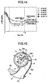
- Fig. 14 is a diagram illustrating the change in the noise level at the same flow rate when the maximum volute angle a M and the ratio R M /R 1 between the maximum volute radius R M and the volute-portion starting radius R 1 are varied.
- Fig. 15 is a diagram illustrating the cross flow fan.
- the outlet-portion starting point i.e., the terminating point of the volute portion 10b and the starting point of the outlet portion 10c
- the volute-portion starting radius i.e., the length of the segment O - F 1 between the center O of the rotating shaft of the impeller and the volute-portion starting point F 1
- R 1 that the maximum volute radius, i.e., the length of the segment O - F 2 at the outlet-portion starting point F 2
- the maximum volute angle i.e., the angle formed by the segments O - F 2 and O - F 1
- an arbitrary point on the volute portion 10b is F
- the length of a segment connecting the center O of the rotating shaft and the arbitrary point F is R
- an angle formed by the segments O - F and O - F 2 is a.
- volute portion 10b By forming the volute portion 10b in the above-described manner, the volute portion 10b bulges more outwardly than in the case of the example scroll casing indicated by the broken lines in Fig. 2, the portion of the blown-out air flow C where the velocity of air flow is fast does not contact the scroll casing 10 at least in the vicinity of the impeller 9. Therefore, the phenomenon disappears in which the pressure fluctuation P, which occurs due to the impingement of the blown-out air flow C upon the scroll casing 10 in the vicinity of the impeller 9, affects the impeller 9 and aggravates the noise, as shown in Fig. 23. Hence, low noise can be attained.
- Optimum ranges are present for the scroll expansion ratio I L and the maximum volute angle a M , which indicate the degree of expansion of the volute portion 10b, so as to obtain a low-noise air conditioner in which even if dust and the like are accumulated on the filters and other portions, the blown-out air flow C is stabilized and the noise does not become aggravated.
- Optimum ranges are present for the ratio between the outlet-portion starting radius R 2 and the outlet-portion terminating radius R 3 and the outlet portion angle a 3 , which indicate the degree of expansion of the outlet portion 10c, so as to obtain a low-noise air conditioner in which even if dust and the like are accumulated on the filters and other portions, the blown-out air flow C is stabilized and the noise does not become aggravated.
- Fig. 17 is a diagram illustrating the relationship between the change in the noise level and the state of the blown-out air flow when the ratio R 3 /R 2 of the outlet-portion terminating radius R 3 to the outlet-portion starting radius R 3 as well as the outlet portion angle a 3 are varied.
- the phenomenon disappears in which the pressure fluctuation, which occurs due to the impingement of the blown-out air flow C upon the scroll casing in the vicinity of the impeller, affects the impeller and aggravates the noise, so that low noise can be attained.
Landscapes
- Engineering & Computer Science (AREA)
- Mechanical Engineering (AREA)
- General Engineering & Computer Science (AREA)
- Chemical & Material Sciences (AREA)
- Combustion & Propulsion (AREA)
- Physics & Mathematics (AREA)
- Thermal Sciences (AREA)
- Structures Of Non-Positive Displacement Pumps (AREA)
Applications Claiming Priority (2)
| Application Number | Priority Date | Filing Date | Title |
|---|---|---|---|
| JP00752998A JP3497073B2 (ja) | 1998-01-19 | 1998-01-19 | 貫流送風機 |
| JP752998 | 1998-01-19 |
Publications (3)
| Publication Number | Publication Date |
|---|---|
| EP0930472A2 true EP0930472A2 (de) | 1999-07-21 |
| EP0930472A3 EP0930472A3 (de) | 2002-09-18 |
| EP0930472B1 EP0930472B1 (de) | 2005-02-23 |
Family
ID=11668317
Family Applications (1)
| Application Number | Title | Priority Date | Filing Date |
|---|---|---|---|
| EP98309350A Expired - Lifetime EP0930472B1 (de) | 1998-01-19 | 1998-11-16 | Querstromlüfter |
Country Status (8)
| Country | Link |
|---|---|
| US (1) | US6086324A (de) |
| EP (1) | EP0930472B1 (de) |
| JP (1) | JP3497073B2 (de) |
| CN (1) | CN1097175C (de) |
| AU (1) | AU738150B2 (de) |
| ES (1) | ES2238751T3 (de) |
| ID (1) | ID21740A (de) |
| TW (1) | TW396247B (de) |
Cited By (8)
| Publication number | Priority date | Publication date | Assignee | Title |
|---|---|---|---|---|
| EP1243864A3 (de) * | 2001-03-23 | 2003-01-02 | Mitsubishi Heavy Industries, Ltd. | Innenraumeinheit und Klimaanlage |
| KR20100076250A (ko) * | 2008-12-26 | 2010-07-06 | 엘지전자 주식회사 | 공기조화장치 |
| EP1813876A3 (de) * | 2006-01-26 | 2011-01-05 | LG Electronics Inc. | Innenraumeinheit einer Klimaanlage |
| EP1975522A4 (de) * | 2006-01-20 | 2011-11-02 | Sharp Kk | Klimaanlage |
| US20130035028A1 (en) * | 2010-04-02 | 2013-02-07 | Gree Electric Appliances, Inc. Of Zhuhai | Indoor Unit of Air Conditioner |
| EP2472190A4 (de) * | 2009-08-25 | 2016-03-16 | Mitsubishi Electric Corp | Gebläseeinheit und damit ausgestattete klimaanlage |
| CN109059232A (zh) * | 2018-10-24 | 2018-12-21 | 奥克斯空调股份有限公司 | 风道结构及空调器 |
| CN113566405A (zh) * | 2021-08-11 | 2021-10-29 | 珠海格力电器股份有限公司 | 风道安装结构及具有其的空调室内机 |
Families Citing this family (32)
| Publication number | Priority date | Publication date | Assignee | Title |
|---|---|---|---|---|
| AU767078B2 (en) | 2000-09-29 | 2003-10-30 | Mitsubishi Denki Kabushiki Kaisha | Air conditioner |
| JP3564414B2 (ja) * | 2001-03-23 | 2004-09-08 | 三菱重工業株式会社 | 室内機ユニット及び空気調和機 |
| JP2002317789A (ja) * | 2001-04-20 | 2002-10-31 | Royal Electric Co Ltd | 超小型横流ファン |
| AU2003277652B2 (en) * | 2002-11-14 | 2006-04-27 | Daikin Industries, Ltd. | Heat exchanger and air conditioner indoor unit |
| JP4196346B2 (ja) * | 2004-03-25 | 2008-12-17 | 三菱電機株式会社 | 空気調和機 |
| KR101073501B1 (ko) * | 2004-05-18 | 2011-10-17 | 삼성전자주식회사 | 다단운전 공기조화기 |
| EP1747917B1 (de) * | 2005-07-28 | 2009-10-21 | ebm-papst St. Georgen GmbH & Co. KG | Heizaggregat |
| KR100768851B1 (ko) * | 2006-05-19 | 2007-10-22 | 엘지전자 주식회사 | 냉장고 |
| KR100751116B1 (ko) * | 2006-05-20 | 2007-08-22 | 엘지전자 주식회사 | 공기 조화기의 실내기 |
| KR100850960B1 (ko) * | 2007-04-04 | 2008-08-08 | 엘지전자 주식회사 | 송풍장치 및 송풍장치가 구비된 냉장고 |
| JP5289554B2 (ja) * | 2009-03-06 | 2013-09-11 | 三菱電機株式会社 | 空気調和機 |
| WO2011016152A1 (ja) | 2009-08-05 | 2011-02-10 | 三菱電機株式会社 | 壁掛け型の空気調和機 |
| CN103953584B (zh) * | 2009-08-25 | 2016-08-24 | 三菱电机株式会社 | 鼓风机及具有该鼓风机的空调机 |
| US8864447B1 (en) * | 2010-07-01 | 2014-10-21 | Sharon K. Humphrey | Low-profile, ceiling-mounted fan |
| JP5269036B2 (ja) * | 2010-11-08 | 2013-08-21 | 三菱電機株式会社 | 貫流ファン、およびそれを備えた空気調和機 |
| CN102954536B (zh) * | 2011-08-30 | 2015-03-04 | 珠海格力电器股份有限公司 | 空调装置 |
| CN103486711B (zh) * | 2012-06-13 | 2017-02-08 | 珠海格力电器股份有限公司 | 室内机 |
| JP2013127254A (ja) * | 2013-01-28 | 2013-06-27 | Mitsubishi Electric Corp | 送風機及びその送風機を備えた空気調和機 |
| JP5862655B2 (ja) * | 2013-12-27 | 2016-02-16 | ダイキン工業株式会社 | 空調室内機 |
| WO2016063397A1 (ja) * | 2014-10-23 | 2016-04-28 | 三菱電機株式会社 | 空気調和機 |
| CN105546666B (zh) * | 2016-01-05 | 2019-05-31 | 青岛海尔空调器有限总公司 | 窗式空调器 |
| US10895388B2 (en) * | 2016-02-03 | 2021-01-19 | Mitsubishi Electric Corporation | Indoor unit air-conditioning apparatus |
| CN106907773A (zh) * | 2017-03-22 | 2017-06-30 | 广东美的制冷设备有限公司 | 蜗舌、风道结构和空调器 |
| CN107166496A (zh) * | 2017-06-30 | 2017-09-15 | 广东美的环境电器制造有限公司 | 风道组件和暖风机 |
| CN109708239B (zh) * | 2019-02-01 | 2024-01-05 | 广东美的暖通设备有限公司 | 新风机 |
| FR3093763B1 (fr) * | 2019-03-15 | 2021-04-02 | Valeo Systemes Thermiques | Module de refroidissement à zone sacrificielle pour véhicule automobile électrique |
| US11536290B2 (en) * | 2020-04-08 | 2022-12-27 | Carrier Corporation | Fan coil unit and air conditioning system |
| CN111780398B (zh) * | 2020-06-12 | 2024-11-01 | 佛山市润千宇知识产权服务有限公司 | 一种仿蜗壳型消声通风装置及其使用方法 |
| EP4012273A1 (de) * | 2020-10-13 | 2022-06-15 | Chongqing Midea Air-Conditioning Equipment Co., Ltd. | Klimaanlage |
| CN115435388A (zh) * | 2021-06-01 | 2022-12-06 | 广东美的暖通设备有限公司 | 壁挂式空调器 |
| CN113738703B (zh) | 2021-09-30 | 2025-07-25 | 珠海格力电器股份有限公司 | 一种贯流风道和出风装置 |
| CN114636197B (zh) * | 2022-03-31 | 2023-09-08 | 广东美的白色家电技术创新中心有限公司 | 贯流风机及空调器 |
Family Cites Families (13)
| Publication number | Priority date | Publication date | Assignee | Title |
|---|---|---|---|---|
| DE1951115B2 (de) * | 1969-10-10 | 1976-10-21 | Böhler-Zenkner GmbH & Co KG Strömungstechnik, 4005 Meerbusch | Querstromgeblaese |
| US4014625A (en) * | 1973-08-20 | 1977-03-29 | Teruo Yamamoto | Transverse flow fan |
| CA1207724A (en) * | 1980-12-25 | 1986-07-15 | Matsushita Electric Industrial Co., Ltd. | Electric fan assembly |
| JPS60233392A (ja) * | 1984-05-07 | 1985-11-20 | Mitsubishi Electric Corp | 貫流形送風機 |
| JPH0830477B2 (ja) * | 1985-11-29 | 1996-03-27 | 三洋電機株式会社 | 横流送風機 |
| KR930006876B1 (ko) * | 1989-06-23 | 1993-07-24 | 가부시끼 가이샤 히다찌세이사꾸쇼 | 관류팬을 사용한 송풍장치 및 공기조화기 |
| CN2118845U (zh) * | 1992-03-10 | 1992-10-14 | 任国金 | 一种横流式双向换气扇 |
| JP3514518B2 (ja) * | 1993-09-29 | 2004-03-31 | 三菱電機株式会社 | 分離型空気調和機 |
| JP3321314B2 (ja) * | 1994-09-30 | 2002-09-03 | 株式会社日本クライメイトシステムズ | 車両用後方空気調和装置 |
| JP2642900B2 (ja) * | 1995-04-14 | 1997-08-20 | 三洋電機株式会社 | 空気調和機 |
| JPH10205828A (ja) * | 1997-01-20 | 1998-08-04 | Daikin Ind Ltd | 空気調和機用室外機 |
| JP3649567B2 (ja) * | 1998-01-12 | 2005-05-18 | 三菱電機株式会社 | 貫流送風機 |
| US5943878A (en) * | 1998-05-22 | 1999-08-31 | American Standard Inc. | Tangential fan scroll and discharged diffuser design |
-
1998
- 1998-01-19 JP JP00752998A patent/JP3497073B2/ja not_active Expired - Fee Related
- 1998-08-11 TW TW087113217A patent/TW396247B/zh not_active IP Right Cessation
- 1998-09-29 US US09/161,760 patent/US6086324A/en not_active Expired - Fee Related
- 1998-09-30 CN CN98120813A patent/CN1097175C/zh not_active Expired - Fee Related
- 1998-11-16 ES ES98309350T patent/ES2238751T3/es not_active Expired - Lifetime
- 1998-11-16 EP EP98309350A patent/EP0930472B1/de not_active Expired - Lifetime
- 1998-11-30 ID IDP981553A patent/ID21740A/id unknown
-
1999
- 1999-01-18 AU AU12130/99A patent/AU738150B2/en not_active Ceased
Cited By (9)
| Publication number | Priority date | Publication date | Assignee | Title |
|---|---|---|---|---|
| EP1243864A3 (de) * | 2001-03-23 | 2003-01-02 | Mitsubishi Heavy Industries, Ltd. | Innenraumeinheit und Klimaanlage |
| EP1975522A4 (de) * | 2006-01-20 | 2011-11-02 | Sharp Kk | Klimaanlage |
| EP1813876A3 (de) * | 2006-01-26 | 2011-01-05 | LG Electronics Inc. | Innenraumeinheit einer Klimaanlage |
| KR20100076250A (ko) * | 2008-12-26 | 2010-07-06 | 엘지전자 주식회사 | 공기조화장치 |
| EP2472190A4 (de) * | 2009-08-25 | 2016-03-16 | Mitsubishi Electric Corp | Gebläseeinheit und damit ausgestattete klimaanlage |
| US20130035028A1 (en) * | 2010-04-02 | 2013-02-07 | Gree Electric Appliances, Inc. Of Zhuhai | Indoor Unit of Air Conditioner |
| CN109059232A (zh) * | 2018-10-24 | 2018-12-21 | 奥克斯空调股份有限公司 | 风道结构及空调器 |
| CN109059232B (zh) * | 2018-10-24 | 2024-05-10 | 奥克斯空调股份有限公司 | 风道结构及空调器 |
| CN113566405A (zh) * | 2021-08-11 | 2021-10-29 | 珠海格力电器股份有限公司 | 风道安装结构及具有其的空调室内机 |
Also Published As
| Publication number | Publication date |
|---|---|
| EP0930472A3 (de) | 2002-09-18 |
| ES2238751T3 (es) | 2005-09-01 |
| TW396247B (en) | 2000-07-01 |
| EP0930472B1 (de) | 2005-02-23 |
| CN1224121A (zh) | 1999-07-28 |
| CN1097175C (zh) | 2002-12-25 |
| US6086324A (en) | 2000-07-11 |
| AU738150B2 (en) | 2001-09-13 |
| JP3497073B2 (ja) | 2004-02-16 |
| AU1213099A (en) | 1999-08-05 |
| JPH11201081A (ja) | 1999-07-27 |
| ID21740A (id) | 1999-07-22 |
Similar Documents
| Publication | Publication Date | Title |
|---|---|---|
| EP0930472B1 (de) | Querstromlüfter | |
| CA2314532C (en) | Blower | |
| US20020172588A1 (en) | Air conditioner | |
| EP1139033B1 (de) | Klimaanlage | |
| US6254336B1 (en) | Sirocco fan having an inclined cutoff | |
| EP0916905B1 (de) | Gebläse für Verdampfer mit Kondensatschleuder | |
| EP2192354A2 (de) | Innenraumeinheit für eine Klimaanlage | |
| JP3764442B2 (ja) | 空気調和機及び貫流送風機及びクロスフローファンのスタビライザー | |
| JP2005240798A (ja) | 送風ファンの構造 | |
| JP6264192B2 (ja) | クロスフローファン及びこれを備える空気調和機 | |
| CN111083931A (zh) | 空调机的室内机 | |
| JP4505885B2 (ja) | 送風機及びこれを用いた空気調和機並びに空気清浄機 | |
| EP3715730B1 (de) | In eine raumdecke eingebettete klimaanlage | |
| JP2001263294A (ja) | 遠心式ターボ型空気機械のインペラ、遠心式ターボ型空気機械、及び空気調和装置 | |
| JP2001132687A (ja) | 遠心形送風機の羽根車および空気調和機 | |
| EP0962716A1 (de) | Klimaanlage | |
| US6298682B1 (en) | Condensate deflector for an air conditioner | |
| KR100751121B1 (ko) | 공기조화기 실내기 | |
| AU2022285467B2 (en) | Wall-mounted air conditioner | |
| JPH06341660A (ja) | 空気調和機用熱交換器 | |
| EP3748238A1 (de) | In eine raumdecke eingebettete klimaanlage | |
| JP2003269738A (ja) | 空気調和機 | |
| JP3068310B2 (ja) | 熱交換装置 | |
| JP3213786B2 (ja) | 送風装置 | |
| JP2951145B2 (ja) | 送風装置 |
Legal Events
| Date | Code | Title | Description |
|---|---|---|---|
| PUAI | Public reference made under article 153(3) epc to a published international application that has entered the european phase |
Free format text: ORIGINAL CODE: 0009012 |
|
| AK | Designated contracting states |
Kind code of ref document: A2 Designated state(s): AT BE CH CY DE DK ES FI FR GB GR IE IT LI LU MC NL PT SE |
|
| AX | Request for extension of the european patent |
Free format text: AL;LT;LV;MK;RO;SI |
|
| PUAL | Search report despatched |
Free format text: ORIGINAL CODE: 0009013 |
|
| AK | Designated contracting states |
Kind code of ref document: A3 Designated state(s): AT BE CH CY DE DK ES FI FR GB GR IE IT LI LU MC NL PT SE |
|
| AX | Request for extension of the european patent |
Free format text: AL;LT;LV;MK;RO;SI |
|
| 17P | Request for examination filed |
Effective date: 20030102 |
|
| AKX | Designation fees paid |
Designated state(s): ES FR GB IT |
|
| REG | Reference to a national code |
Ref country code: DE Ref legal event code: 8566 |
|
| 17Q | First examination report despatched |
Effective date: 20040429 |
|
| GRAP | Despatch of communication of intention to grant a patent |
Free format text: ORIGINAL CODE: EPIDOSNIGR1 |
|
| GRAS | Grant fee paid |
Free format text: ORIGINAL CODE: EPIDOSNIGR3 |
|
| GRAA | (expected) grant |
Free format text: ORIGINAL CODE: 0009210 |
|
| AK | Designated contracting states |
Kind code of ref document: B1 Designated state(s): ES FR GB IT |
|
| REG | Reference to a national code |
Ref country code: GB Ref legal event code: FG4D |
|
| REG | Reference to a national code |
Ref country code: IE Ref legal event code: FG4D |
|
| REG | Reference to a national code |
Ref country code: ES Ref legal event code: FG2A Ref document number: 2238751 Country of ref document: ES Kind code of ref document: T3 |
|
| PLBE | No opposition filed within time limit |
Free format text: ORIGINAL CODE: 0009261 |
|
| 26N | No opposition filed |
Effective date: 20051124 |
|
| ET | Fr: translation filed | ||
| REG | Reference to a national code |
Ref country code: GB Ref legal event code: 746 Effective date: 20090330 |
|
| PGFP | Annual fee paid to national office [announced via postgrant information from national office to epo] |
Ref country code: GB Payment date: 20101110 Year of fee payment: 13 |
|
| PGFP | Annual fee paid to national office [announced via postgrant information from national office to epo] |
Ref country code: FR Payment date: 20111118 Year of fee payment: 14 Ref country code: ES Payment date: 20111122 Year of fee payment: 14 |
|
| PGFP | Annual fee paid to national office [announced via postgrant information from national office to epo] |
Ref country code: IT Payment date: 20111111 Year of fee payment: 14 |
|
| GBPC | Gb: european patent ceased through non-payment of renewal fee |
Effective date: 20121116 |
|
| REG | Reference to a national code |
Ref country code: FR Ref legal event code: ST Effective date: 20130731 |
|
| PG25 | Lapsed in a contracting state [announced via postgrant information from national office to epo] |
Ref country code: IT Free format text: LAPSE BECAUSE OF NON-PAYMENT OF DUE FEES Effective date: 20121116 |
|
| PG25 | Lapsed in a contracting state [announced via postgrant information from national office to epo] |
Ref country code: GB Free format text: LAPSE BECAUSE OF NON-PAYMENT OF DUE FEES Effective date: 20121116 Ref country code: FR Free format text: LAPSE BECAUSE OF NON-PAYMENT OF DUE FEES Effective date: 20121130 |
|
| REG | Reference to a national code |
Ref country code: ES Ref legal event code: FD2A Effective date: 20140305 |
|
| PG25 | Lapsed in a contracting state [announced via postgrant information from national office to epo] |
Ref country code: ES Free format text: LAPSE BECAUSE OF NON-PAYMENT OF DUE FEES Effective date: 20121117 |