EP3715730B1 - In eine raumdecke eingebettete klimaanlage - Google Patents
In eine raumdecke eingebettete klimaanlage Download PDFInfo
- Publication number
- EP3715730B1 EP3715730B1 EP20157694.9A EP20157694A EP3715730B1 EP 3715730 B1 EP3715730 B1 EP 3715730B1 EP 20157694 A EP20157694 A EP 20157694A EP 3715730 B1 EP3715730 B1 EP 3715730B1
- Authority
- EP
- European Patent Office
- Prior art keywords
- air
- deflector plate
- surface portion
- projections
- direction deflector
- Prior art date
- Legal status (The legal status is an assumption and is not a legal conclusion. Google has not performed a legal analysis and makes no representation as to the accuracy of the status listed.)
- Active
Links
Images


Classifications
-
- F—MECHANICAL ENGINEERING; LIGHTING; HEATING; WEAPONS; BLASTING
- F24—HEATING; RANGES; VENTILATING
- F24F—AIR-CONDITIONING; AIR-HUMIDIFICATION; VENTILATION; USE OF AIR CURRENTS FOR SCREENING
- F24F13/00—Details common to, or for air-conditioning, air-humidification, ventilation or use of air currents for screening
- F24F13/02—Ducting arrangements
- F24F13/06—Outlets for directing or distributing air into rooms or spaces, e.g. ceiling air diffuser
- F24F13/072—Outlets for directing or distributing air into rooms or spaces, e.g. ceiling air diffuser of elongated shape, e.g. between ceiling panels
-
- F—MECHANICAL ENGINEERING; LIGHTING; HEATING; WEAPONS; BLASTING
- F24—HEATING; RANGES; VENTILATING
- F24F—AIR-CONDITIONING; AIR-HUMIDIFICATION; VENTILATION; USE OF AIR CURRENTS FOR SCREENING
- F24F1/00—Room units for air-conditioning, e.g. separate or self-contained units or units receiving primary air from a central station
- F24F1/0007—Indoor units, e.g. fan coil units
- F24F1/0011—Indoor units, e.g. fan coil units characterised by air outlets
-
- F—MECHANICAL ENGINEERING; LIGHTING; HEATING; WEAPONS; BLASTING
- F24—HEATING; RANGES; VENTILATING
- F24F—AIR-CONDITIONING; AIR-HUMIDIFICATION; VENTILATION; USE OF AIR CURRENTS FOR SCREENING
- F24F1/00—Room units for air-conditioning, e.g. separate or self-contained units or units receiving primary air from a central station
- F24F1/0007—Indoor units, e.g. fan coil units
- F24F1/0043—Indoor units, e.g. fan coil units characterised by mounting arrangements
- F24F1/0047—Indoor units, e.g. fan coil units characterised by mounting arrangements mounted in the ceiling or at the ceiling
-
- F—MECHANICAL ENGINEERING; LIGHTING; HEATING; WEAPONS; BLASTING
- F24—HEATING; RANGES; VENTILATING
- F24F—AIR-CONDITIONING; AIR-HUMIDIFICATION; VENTILATION; USE OF AIR CURRENTS FOR SCREENING
- F24F13/00—Details common to, or for air-conditioning, air-humidification, ventilation or use of air currents for screening
- F24F13/08—Air-flow control members, e.g. louvres, grilles, flaps or guide plates
- F24F13/081—Air-flow control members, e.g. louvres, grilles, flaps or guide plates for guiding air around a curve
-
- F—MECHANICAL ENGINEERING; LIGHTING; HEATING; WEAPONS; BLASTING
- F24—HEATING; RANGES; VENTILATING
- F24F—AIR-CONDITIONING; AIR-HUMIDIFICATION; VENTILATION; USE OF AIR CURRENTS FOR SCREENING
- F24F13/00—Details common to, or for air-conditioning, air-humidification, ventilation or use of air currents for screening
- F24F13/08—Air-flow control members, e.g. louvres, grilles, flaps or guide plates
- F24F13/10—Air-flow control members, e.g. louvres, grilles, flaps or guide plates movable, e.g. dampers
- F24F13/14—Air-flow control members, e.g. louvres, grilles, flaps or guide plates movable, e.g. dampers built up of tilting members, e.g. louvre
- F24F13/15—Air-flow control members, e.g. louvres, grilles, flaps or guide plates movable, e.g. dampers built up of tilting members, e.g. louvre with parallel simultaneously tiltable lamellae
-
- F—MECHANICAL ENGINEERING; LIGHTING; HEATING; WEAPONS; BLASTING
- F24—HEATING; RANGES; VENTILATING
- F24F—AIR-CONDITIONING; AIR-HUMIDIFICATION; VENTILATION; USE OF AIR CURRENTS FOR SCREENING
- F24F13/00—Details common to, or for air-conditioning, air-humidification, ventilation or use of air currents for screening
- F24F13/08—Air-flow control members, e.g. louvres, grilles, flaps or guide plates
- F24F13/10—Air-flow control members, e.g. louvres, grilles, flaps or guide plates movable, e.g. dampers
- F24F13/14—Air-flow control members, e.g. louvres, grilles, flaps or guide plates movable, e.g. dampers built up of tilting members, e.g. louvre
-
- F—MECHANICAL ENGINEERING; LIGHTING; HEATING; WEAPONS; BLASTING
- F24—HEATING; RANGES; VENTILATING
- F24F—AIR-CONDITIONING; AIR-HUMIDIFICATION; VENTILATION; USE OF AIR CURRENTS FOR SCREENING
- F24F13/00—Details common to, or for air-conditioning, air-humidification, ventilation or use of air currents for screening
- F24F13/20—Casings or covers
Definitions
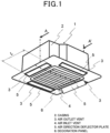
- a ceiling embedded air conditioner of this type there is conventionally known a ceiling embedded air conditioner 100 that is made up, as shown in Fig. 6 , of a casing 101 and a decoration panel 105 provided at a bottom surface of the casing 101 and including a plurality of air outlet vents 102, an air inlet vent 103, and air direction deflector plates 104 (refer to, for example, Patent Literature 1, that is, Japanese Patent Laid-Open No. 2000-205642 ).
- Patent Literature 2 JP H08-86504 discloses an air conditioning machine having a main body, accommodated in a ceiling, and a panel on which an air outlet port and an air suction port are disposed close to each other. A projection is provided on the inside surface of the air outlet port of a chamber so as to blockade 20% or more of a width of an outlet passage across the whole area of lengthwise direction of the outlet passage.
- Patent Literature 3 JP 2007-24345 discloses an air conditioner installed on a ceiling and having an indoor unit provided with a plurality of supply openings composed of an inner air trunk wall and an outer air trunk wall, and faced to a lower face, and a suction opening.
- the air conditioner further comprises vanes respectively mounted on the supply openings for deflecting the direction of the air supplied indoors and having a bent portion bent in the direction separating from the inner air trunk wall at upstream-side portion cassette embedded air conditioner for preventing dew condensation on an outlet at a time of cooling operation by improving a vane (wind deflector) shape and an outlet shape.
- a ceiling embedded air conditioner as defined in claim 1, including, inter alia, an air outlet vent, and in the ceiling embedded air conditioner, the air outlet vent includes an inner air path and an outer air path, the inner air path is made up of a flat surface portion on an upstream side and a curved surface portion on a downstream side, and a plurality of projections are provided at an end portion of the curved surface portion.
- an air flow flowing in a substantially vertical direction from an upstream of the air outlet vent is allowed to let out while being guided from the inner air path in the air outlet vent towards the air direction deflector plate.
- the air direction deflector plate opens at a small angle during a cooling operation, the air is allowed to flow along the air direction deflector plate, whereby the generation of condensation can be prevented which would otherwise be caused by air flowing separate from the front surface portion (the lower surface side) of the air direction deflector plate during such a cooling operation.
- the invention provides a ceiling embedded air conditioner as defined in appended claim 1.
- the air flow colliding against the projection at the air outlet vent generates a longitudinal vortex and flows along the surface of the air direction deflector plate.
- an air flow flowing in a substantially vertical direction from an upstream of the air outlet vent is allowed to let out while being guided from the inner air path in the air outlet vent towards the air direction deflector plate, and even though an opening area opened by the air direction deflector plate in the air outlet vent is small, that is, the air direction deflector plate opens at a small angle, the air is allowed to flow without separating from the front surface portion (the lower surface side) of the air direction deflector plate.
- the longitudinal vortex generated at the projection is ensured to arrive at the air direction deflector plate while reducing the resistance generated by the projection to thereby generate an air flow that flows towards the front surface portion (the lower surface side) of the air direction deflector plate.
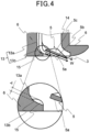
- Fig. 4 shows a partially sectional perspective view and a partially enlarged view near the air outlet vent in a decoration panel of the ceiling embedded air conditioner according to the first embodiment of the present invention in the cross section, taken along the line A-A' in Fig. 1 .
- the ceiling embedded air conditioner 1 is installed in a recessed portion on a ceiling 50 in such a manner as to be suspended from the ceiling 50 with suspension bolts 51.
- the air flow W let out from the centrifugal air blower 7 is heated by the heat exchanger 10 for a heating operation and is cooled by the heat exchanger 10 for a cooling operation, whereafter the air flow W passes through the internal air path 3a to be let out into the inside of the room from the air outlet vent 3 that is opened as a result of the rotation of the air direction deflector plate 5.
- the air direction deflector plate 5 changes not only an opening area in the air outlet vent 3 but also an air blowing direction as a result of the motor 16 being rotated in a rotational direction C.
- the air direction deflector plate 5 opens at a small angle during a cooling operation, the air flow is allowed to flow along the air direction deflector plate 5, whereby the generation of condensation can be prevented which would otherwise be caused by separation of the air flow from the front surface portion 5a of the air direction deflector plate 5 during a cooling operation.
- the projection 15 in this embodiment is given a substantially oval shape in which a major axis constitutes a flowing direction, and for the width L of the air outlet vent 3 shown in Fig. 1 , a size of the projection 15 becomes such that a major axis L1 is 0.005L to 0.02L, a minor axis L2 is 0.001L to 0.01L, a height h is 0.001L to 0.01L, and an interval P at which the projections 15 are provided in a width direction of the air outlet vent 3 is 0.025L to 0.075L for the width L of the air outlet vent 3, whereby the flowing direction of the air flow is changed so that the air flow is allowed to flow along the front surface portion 5a of the air direction deflector plate 5 by increasing the air flow flowing near the curved surface portion 13b by generating a longitudinal vortex by the projection 15 without increasing excessively the resistance of the air flow by the projection 15.
- the plurality of irregular portions 15a that are smaller than the plurality of projections are provided on the surface of the projection 15, resistance generated when the air flow collides against the projection 15 is reduced, and the air flow is kept flowing along the projection 15 by a fine vortex generated in the vicinity of a wall surface of the projection 15, whereby a longitudinal vortex generated on an upstream side is prevented from being combined with a longitudinal vortex generated adjacent thereto.
- the longitudinal vortex generated at the projection 15 is ensured to arrive at the air direction deflector plate 5 while reducing the resistance by the projection 15, whereby an air flow is generated which flows towards the front surface portion (the lower surface side) 5a of the air direction deflector plate 5.
- the projection 15 is given the substantially oval shape in which the major axis constitutes the flowing direction, whereby compared with a circular shape, a smaller scaled vortex is generated when the air flow collides against the projection 15, and the air flow is guided by the major axis.
- the longitudinal vortex generated at the projection 15 is ensured to be conveyed to the front surface portion (the lower surface side) 5a of the air direction deflector plate 5.
- the air direction deflector plate opens at a small angle during a cooling operation particularly with air flowing weakly at a low air velocity, the air is still allowed to flow along the air direction deflector plate, whereby the generation of condensation can be prevented which would otherwise be caused by the air flow flowing separate from the front surface portion (the lower surface side) of the air direction deflector plate during a cooling operation.
- the number of projections 15 is not particularly limited, provided that the intervals P are maintained, and longitudinal vortexes are generated at the projections 15 by an amount of air let out from the air outlet vent 3 to increase an air flow flowing in the vicinity of the curved surface portion 13b without increasing excessively a pressure loss of an air flow at each of the projections 15, and the number of air flows whose flowing directions are changed so as to flow along the front surface portion 5a of the air direction deflector plate 5 is changed.
- Fig. 5 shows a partially sectional perspective view and a partially enlarged view of an air outlet vent, which is in use, of a ceiling embedded air conditioner according to a second embodiment of the present invention.
- Like reference signs will be given to like or corresponding portions to those of the first embodiment, so that part of a description of the second embodiment is omitted.
- a plurality of projections 15 are provided at intervals P at an end portion of a curved surface portion 13b over a distance of 0.3L or smaller from opposite sides of an air outlet vent 3.
- the air flow is allowed to flow along the front surface portion (the lower surface side) 5a of the air direction deflector plate 5, whereby the generation of condensation can be prevented which would otherwise be caused by the air flow flowing separate from the front surface portion (the lower surface side) 5a of the air direction deflector plate 5 as in a cooling operation.
- the projection 15 in this embodiment is given a substantially oval shape in which a major axis constitutes a flowing direction, and for the width L of the air outlet vent 3 shown in Fig. 1 , a size of the projection 15 becomes such that a major axis L1 is 0.005L to 0.02L, a minor axis L2 is 0.001L to 0.01L, a height h is 0.001L to 0.01L, and an interval P at which the projections 15 are provided in a width direction of the air outlet vent 3 is 0.025L to 0.075L for the width L of the air outlet vent 3, whereby the flowing direction of the air flow is changed so that the air flow is allowed to flow along the front surface portion 5a of the air direction deflector plate 5 by increasing the air flow flowing in the vicinity of the curved surface portion 13b by generating a longitudinal vortex by the projection 15 without increasing excessively the resistance of the air flow by the projection 15.
- the longitudinal vortex generated at the projection 15 is ensured to arrive at the air direction deflector plate 5 while reducing the resistance by the projection 15, whereby an air flow is generated which flows towards the front surface portion (the lower surface side) 5a of the air direction deflector plate 5.
- the air flow is allowed to flow along the air direction deflector plate 5, whereby the generation of condensation can be prevented which would otherwise be caused by the air flow flowing separate from the front surface portion (the lower surface side) 5a of the air direction deflector plate 5 during a cooling operation.
- the projection 15 is given the substantially oval shape in which the major axis constitutes the flowing direction, compared with a circular shape, a smaller scaled vortex is generated when the air flow collides against the projection 15, and the air flow is guided by the major axis of the projection.
- the longitudinal vortex generated at the projection 15 is ensured to be conveyed to the front surface portion (the lower surface side) 5a of the air direction deflector plate 5.
- the air flow is allowed to flow along the air direction deflector plate, whereby the generation of condensation can be prevented which would otherwise be caused by the air flow flowing separate from the front surface portion (the lower surface side) of the air direction deflector plate as in a cooling operation.
- the intervals P at which the projections 15 are provided are made to be irregular intervals, whereby longitudinal vortexes generated by the projections 15 are made uneven, and a peak in a specific frequency band of noise generated at the air outlet vent 3 is suppressed, thereby making it possible to reduce the noise.
- the number of projections 15 is not particularly limited, provided that the intervals P are maintained, and longitudinal vortexes are generated at the projections 15 by an amount of air let out from the air outlet vent 3 to increase an air flow flowing in the vicinity of the curved surface portion 13b without increasing excessively a pressure loss of an air flow at each of the projections 15, and the number of air flows whose flowing directions are changed so as to flow along the front surface portion 5a of the air direction deflector plate 5 is changed.
- the ceiling embedded air conditioner prevents the generation of condensation on a lower surface of the air direction deflector plate which would otherwise be caused by the air flow from the upstream of the internal air path flowing separate from a front edge portion of the air direction deflector plate and can be applied to an air conditioner, an air cleaner, a dryer, an air conditioner for a motor vehicle, and the like.
Landscapes
- Engineering & Computer Science (AREA)
- Chemical & Material Sciences (AREA)
- Combustion & Propulsion (AREA)
- Mechanical Engineering (AREA)
- General Engineering & Computer Science (AREA)
- Air-Flow Control Members (AREA)
- Devices For Blowing Cold Air, Devices For Blowing Warm Air, And Means For Preventing Water Condensation In Air Conditioning Units (AREA)
- Air Filters, Heat-Exchange Apparatuses, And Housings Of Air-Conditioning Units (AREA)
- Duct Arrangements (AREA)
Claims (3)
- Deckeneinbau-Klimaanlage, umfassend ein in eine Decke eingebettetes Gehäuse (2), eine an einer Bodenfläche des Gehäuses vorgesehene Dekorplatte (6), eine in der Dekorplatte vorgesehene Lufteinlassöffnung (4), um Innenluft in einem Inneren eines Raums in einen Innenraum des Gehäuses strömen zu lassen, eine Luftauslassöffnung (3), die dazu konfiguriert ist, die Luft aus der Lufteinlassöffnung in das Innere des Gehäuses und aus der Luftauslassöffnung in das Innere des Raums strömen zu lassen, und eine an der Luftauslassöffnung vorgesehene Luftrichtungs-Ablenkplatte (5), die dazu konfiguriert ist, sich um eine drehbare Welle (5c) an einem Ende der Luftrichtungs-Ablenkplatte zu drehen, um eine Richtung der Luft zu steuern,wobei die Luftauslassöffnung einen inneren Luftpfad (13) und einen äußeren Luftpfad (14) umfasst,wobei der innere Luftpfad aus einem flachen Oberflächenabschnitt (13a) auf einer stromaufwärts gelegenen Seite und einem gekrümmten Oberflächenabschnitt (13b) auf einer stromabwärts gelegenen Seite gebildet ist, undwobei mehrere Vorsprünge (15) an einem Endabschnitt des gekrümmten Oberflächenabschnitts vorgesehen sind, so dass ein Luftstrom, der mit den mehreren Vorsprüngen kollidiert, einen Längswirbel erzeugt und entlang eines vorderen Oberflächenabschnitts (5a) strömt, der an der Luftstrom-Ablenkplatte an einer unteren Oberflächenseite der Luftstrom-Ablenkplatte vorgesehen ist,dadurch gekennzeichnet, dasseine Oberfläche jedes der mehreren Vorsprünge mehrere unregelmäßige Abschnitte (15a) umfasst, die kleiner sind als die mehreren Vorsprünge.
- Deckeneinbau-Klimaanlage nach Anspruch 1,
wobei jeder der mehreren Vorsprünge eine ovale Form aufweist, bei der eine Hauptachse eine Fließrichtung darstellt, wenn der Vorsprung aus einer normalen Richtung davon betrachtet wird. - Deckeneinbau-Klimaanlage nach Anspruch 1 oder 2,
wobei die mehreren Vorsprünge in Abständen (P) über eine Strecke von 0,3 L oder weniger von gegenüberliegenden Seiten der Luftauslassöffnung (3) für eine Breite L der Luftauslassöffnung (3) vorgesehen sind.
Applications Claiming Priority (1)
| Application Number | Priority Date | Filing Date | Title |
|---|---|---|---|
| JP2019060092A JP7232986B2 (ja) | 2019-03-27 | 2019-03-27 | 天井埋め込み形空気調和機 |
Publications (3)
| Publication Number | Publication Date |
|---|---|
| EP3715730A1 EP3715730A1 (de) | 2020-09-30 |
| EP3715730B1 true EP3715730B1 (de) | 2024-12-04 |
| EP3715730C0 EP3715730C0 (de) | 2024-12-04 |
Family
ID=69631467
Family Applications (1)
| Application Number | Title | Priority Date | Filing Date |
|---|---|---|---|
| EP20157694.9A Active EP3715730B1 (de) | 2019-03-27 | 2020-02-17 | In eine raumdecke eingebettete klimaanlage |
Country Status (3)
| Country | Link |
|---|---|
| EP (1) | EP3715730B1 (de) |
| JP (1) | JP7232986B2 (de) |
| CN (1) | CN111750436B (de) |
Families Citing this family (3)
| Publication number | Priority date | Publication date | Assignee | Title |
|---|---|---|---|---|
| CN113108370A (zh) * | 2021-05-18 | 2021-07-13 | 宁波康韩瑞电器有限公司 | 一种导风组件及空调器 |
| CN113324285A (zh) * | 2021-07-05 | 2021-08-31 | 珠海格力节能环保制冷技术研究中心有限公司 | 空调室内机、空调器、空调控制方法、装置及空调 |
| CN114791126B (zh) * | 2022-04-28 | 2023-09-08 | 广东美的白色家电技术创新中心有限公司 | 一种天花机 |
Family Cites Families (22)
| Publication number | Priority date | Publication date | Assignee | Title |
|---|---|---|---|---|
| JPH04117318U (ja) * | 1991-03-29 | 1992-10-21 | ダイキン工業株式会社 | 空気調和機の室内ユニツト |
| JPH0886504A (ja) * | 1994-09-16 | 1996-04-02 | Hitachi Air Conditioning & Refrig Co Ltd | 空気調和機 |
| JP3240854B2 (ja) * | 1994-09-26 | 2001-12-25 | 三菱電機株式会社 | 空気調和機の吹出口 |
| JP3198936B2 (ja) * | 1996-08-30 | 2001-08-13 | 三菱電機株式会社 | 吹き出し気流制御装置 |
| JP2000205642A (ja) | 1999-01-14 | 2000-07-28 | Mitsubishi Electric Corp | 天井埋め込み形空気調和機 |
| JP3408983B2 (ja) * | 1999-01-25 | 2003-05-19 | 三菱電機株式会社 | 天井埋込型空気調和機 |
| JP2006336961A (ja) * | 2005-06-03 | 2006-12-14 | Matsushita Electric Ind Co Ltd | 天井埋込型空気調和機 |
| JP2007024345A (ja) | 2005-07-12 | 2007-02-01 | Mitsubishi Electric Corp | 空気調和機 |
| JP2008190779A (ja) * | 2007-02-05 | 2008-08-21 | Mitsubishi Electric Corp | 空気調和機 |
| DE102007025749A1 (de) * | 2007-06-01 | 2008-12-11 | Wacker Chemie Ag | Leuchtkörper-Silicon-Formteil |
| JP2009014330A (ja) | 2007-07-03 | 2009-01-22 | Mika Yamaji | 空気調和機 |
| TR201909786T4 (tr) * | 2007-10-25 | 2019-07-22 | Toshiba Carrier Corp | Tavana gömülebilen klima. |
| KR101517346B1 (ko) * | 2008-09-19 | 2015-05-06 | 삼성전자 주식회사 | 천장형 공기조화기 |
| JP5247784B2 (ja) * | 2010-10-04 | 2013-07-24 | 三菱電機株式会社 | 空気調和機 |
| JP5923871B2 (ja) * | 2011-05-31 | 2016-05-25 | ダイキン工業株式会社 | 空気調和機用室内機 |
| CN202613701U (zh) | 2012-05-09 | 2012-12-19 | 广东美的电器股份有限公司 | 一种空调导风板 |
| CN103512176B (zh) * | 2012-06-15 | 2018-04-27 | 乐金电子(天津)电器有限公司 | 空调器面板 |
| KR102032192B1 (ko) * | 2015-10-23 | 2019-10-15 | 삼성전자주식회사 | 공기조화기 |
| JP6233398B2 (ja) | 2015-12-22 | 2017-11-22 | ダイキン工業株式会社 | 空気調和装置の室内ユニット |
| JP6477737B2 (ja) | 2017-01-31 | 2019-03-06 | ダイキン工業株式会社 | 室内機 |
| CN207936256U (zh) * | 2018-01-12 | 2018-10-02 | 青岛海尔空调器有限总公司 | 壁挂式空调室内机 |
| EP3842703A4 (de) | 2018-08-21 | 2022-03-30 | Hitachi-Johnson Controls Air Conditioning, Inc. | Innenraumeinheit für klimaanlage |
-
2019
- 2019-03-27 JP JP2019060092A patent/JP7232986B2/ja active Active
-
2020
- 2020-02-17 EP EP20157694.9A patent/EP3715730B1/de active Active
- 2020-02-18 CN CN202010098648.2A patent/CN111750436B/zh not_active Expired - Fee Related
Also Published As
| Publication number | Publication date |
|---|---|
| CN111750436B (zh) | 2023-10-03 |
| EP3715730A1 (de) | 2020-09-30 |
| CN111750436A (zh) | 2020-10-09 |
| JP2020159637A (ja) | 2020-10-01 |
| EP3715730C0 (de) | 2024-12-04 |
| JP7232986B2 (ja) | 2023-03-06 |
Similar Documents
| Publication | Publication Date | Title |
|---|---|---|
| EP2463599B1 (de) | Klimaanlage zum aufhängen an der wand | |
| CN103154629B (zh) | 空调机 | |
| JP3624813B2 (ja) | 空気調和装置の化粧パネル、吹出口ユニット、及び空気調和装置 | |
| EP3715730B1 (de) | In eine raumdecke eingebettete klimaanlage | |
| US6338676B1 (en) | Air conditioner | |
| EP2345852B1 (de) | Raumeinheit für bodenmontierte klimaanlage | |
| JP2007024345A (ja) | 空気調和機 | |
| EP2957773B1 (de) | Klimaanlage | |
| JP3116874B2 (ja) | 空気調和装置の空気吹出口構造 | |
| EP3193097B1 (de) | Inneneinheit für eine klimaanlage | |
| EP3048375B1 (de) | Klimaanlage | |
| JP3624814B2 (ja) | 空気調和装置の化粧パネル、吹出口ユニット、及び空気調和装置 | |
| JPH10197045A (ja) | 空気調和機の吹出案内羽根構造 | |
| JP3438323B2 (ja) | 天井埋込型空気調和装置及び該装置の水平羽根構造 | |
| JP3521813B2 (ja) | 空気調和機 | |
| JP4980440B2 (ja) | 空気調和機 | |
| JP2000120582A (ja) | 遠心送風機 | |
| JPH09217943A (ja) | 壁埋込みエアコン用パネル | |
| EP1703217A1 (de) | Klimaanlage | |
| CN117677800A (zh) | 空调机组的排风口 | |
| JP7025682B2 (ja) | ダクト型空気調和機 | |
| WO2021085086A1 (ja) | 送風機 | |
| JP2002022256A (ja) | 空気調和機の風向制御板 | |
| JP2000343932A (ja) | 車両用空調ユニット | |
| JPH08313040A (ja) | 空気調和装置の風向調整構造 |
Legal Events
| Date | Code | Title | Description |
|---|---|---|---|
| PUAI | Public reference made under article 153(3) epc to a published international application that has entered the european phase |
Free format text: ORIGINAL CODE: 0009012 |
|
| STAA | Information on the status of an ep patent application or granted ep patent |
Free format text: STATUS: THE APPLICATION HAS BEEN PUBLISHED |
|
| AK | Designated contracting states |
Kind code of ref document: A1 Designated state(s): AL AT BE BG CH CY CZ DE DK EE ES FI FR GB GR HR HU IE IS IT LI LT LU LV MC MK MT NL NO PL PT RO RS SE SI SK SM TR |
|
| AX | Request for extension of the european patent |
Extension state: BA ME |
|
| STAA | Information on the status of an ep patent application or granted ep patent |
Free format text: STATUS: REQUEST FOR EXAMINATION WAS MADE |
|
| 17P | Request for examination filed |
Effective date: 20210128 |
|
| RBV | Designated contracting states (corrected) |
Designated state(s): AL AT BE BG CH CY CZ DE DK EE ES FI FR GB GR HR HU IE IS IT LI LT LU LV MC MK MT NL NO PL PT RO RS SE SI SK SM TR |
|
| STAA | Information on the status of an ep patent application or granted ep patent |
Free format text: STATUS: EXAMINATION IS IN PROGRESS |
|
| 17Q | First examination report despatched |
Effective date: 20240304 |
|
| GRAP | Despatch of communication of intention to grant a patent |
Free format text: ORIGINAL CODE: EPIDOSNIGR1 |
|
| STAA | Information on the status of an ep patent application or granted ep patent |
Free format text: STATUS: GRANT OF PATENT IS INTENDED |
|
| INTG | Intention to grant announced |
Effective date: 20240717 |
|
| GRAS | Grant fee paid |
Free format text: ORIGINAL CODE: EPIDOSNIGR3 |
|
| GRAA | (expected) grant |
Free format text: ORIGINAL CODE: 0009210 |
|
| STAA | Information on the status of an ep patent application or granted ep patent |
Free format text: STATUS: THE PATENT HAS BEEN GRANTED |
|
| AK | Designated contracting states |
Kind code of ref document: B1 Designated state(s): AL AT BE BG CH CY CZ DE DK EE ES FI FR GB GR HR HU IE IS IT LI LT LU LV MC MK MT NL NO PL PT RO RS SE SI SK SM TR |
|
| REG | Reference to a national code |
Ref country code: CH Ref legal event code: EP |
|
| REG | Reference to a national code |
Ref country code: DE Ref legal event code: R096 Ref document number: 602020042350 Country of ref document: DE |
|
| REG | Reference to a national code |
Ref country code: IE Ref legal event code: FG4D |
|
| U01 | Request for unitary effect filed |
Effective date: 20241220 |
|
| U07 | Unitary effect registered |
Designated state(s): AT BE BG DE DK EE FI FR IT LT LU LV MT NL PT RO SE SI Effective date: 20250113 |
|
| U20 | Renewal fee for the european patent with unitary effect paid |
Year of fee payment: 6 Effective date: 20250221 |
|
| PG25 | Lapsed in a contracting state [announced via postgrant information from national office to epo] |
Ref country code: HR Free format text: LAPSE BECAUSE OF FAILURE TO SUBMIT A TRANSLATION OF THE DESCRIPTION OR TO PAY THE FEE WITHIN THE PRESCRIBED TIME-LIMIT Effective date: 20241204 |
|
| PG25 | Lapsed in a contracting state [announced via postgrant information from national office to epo] |
Ref country code: ES Free format text: LAPSE BECAUSE OF FAILURE TO SUBMIT A TRANSLATION OF THE DESCRIPTION OR TO PAY THE FEE WITHIN THE PRESCRIBED TIME-LIMIT Effective date: 20241204 |
|
| PG25 | Lapsed in a contracting state [announced via postgrant information from national office to epo] |
Ref country code: NO Free format text: LAPSE BECAUSE OF FAILURE TO SUBMIT A TRANSLATION OF THE DESCRIPTION OR TO PAY THE FEE WITHIN THE PRESCRIBED TIME-LIMIT Effective date: 20250304 |
|
| PG25 | Lapsed in a contracting state [announced via postgrant information from national office to epo] |
Ref country code: GR Free format text: LAPSE BECAUSE OF FAILURE TO SUBMIT A TRANSLATION OF THE DESCRIPTION OR TO PAY THE FEE WITHIN THE PRESCRIBED TIME-LIMIT Effective date: 20250305 |
|
| PG25 | Lapsed in a contracting state [announced via postgrant information from national office to epo] |
Ref country code: RS Free format text: LAPSE BECAUSE OF FAILURE TO SUBMIT A TRANSLATION OF THE DESCRIPTION OR TO PAY THE FEE WITHIN THE PRESCRIBED TIME-LIMIT Effective date: 20250304 |
|
| PG25 | Lapsed in a contracting state [announced via postgrant information from national office to epo] |
Ref country code: SM Free format text: LAPSE BECAUSE OF FAILURE TO SUBMIT A TRANSLATION OF THE DESCRIPTION OR TO PAY THE FEE WITHIN THE PRESCRIBED TIME-LIMIT Effective date: 20241204 |
|
| PG25 | Lapsed in a contracting state [announced via postgrant information from national office to epo] |
Ref country code: PL Free format text: LAPSE BECAUSE OF FAILURE TO SUBMIT A TRANSLATION OF THE DESCRIPTION OR TO PAY THE FEE WITHIN THE PRESCRIBED TIME-LIMIT Effective date: 20241204 |
|
| PG25 | Lapsed in a contracting state [announced via postgrant information from national office to epo] |
Ref country code: IS Free format text: LAPSE BECAUSE OF FAILURE TO SUBMIT A TRANSLATION OF THE DESCRIPTION OR TO PAY THE FEE WITHIN THE PRESCRIBED TIME-LIMIT Effective date: 20250404 |
|
| PG25 | Lapsed in a contracting state [announced via postgrant information from national office to epo] |
Ref country code: SK Free format text: LAPSE BECAUSE OF FAILURE TO SUBMIT A TRANSLATION OF THE DESCRIPTION OR TO PAY THE FEE WITHIN THE PRESCRIBED TIME-LIMIT Effective date: 20241204 |
|
| PG25 | Lapsed in a contracting state [announced via postgrant information from national office to epo] |
Ref country code: CZ Free format text: LAPSE BECAUSE OF FAILURE TO SUBMIT A TRANSLATION OF THE DESCRIPTION OR TO PAY THE FEE WITHIN THE PRESCRIBED TIME-LIMIT Effective date: 20241204 |
|
| PG25 | Lapsed in a contracting state [announced via postgrant information from national office to epo] |
Ref country code: MC Free format text: LAPSE BECAUSE OF FAILURE TO SUBMIT A TRANSLATION OF THE DESCRIPTION OR TO PAY THE FEE WITHIN THE PRESCRIBED TIME-LIMIT Effective date: 20241204 |
|
| REG | Reference to a national code |
Ref country code: CH Ref legal event code: PL |
|
| PLBE | No opposition filed within time limit |
Free format text: ORIGINAL CODE: 0009261 |
|
| STAA | Information on the status of an ep patent application or granted ep patent |
Free format text: STATUS: NO OPPOSITION FILED WITHIN TIME LIMIT |
|
| PG25 | Lapsed in a contracting state [announced via postgrant information from national office to epo] |
Ref country code: CH Free format text: LAPSE BECAUSE OF NON-PAYMENT OF DUE FEES Effective date: 20250228 |
|
| 26N | No opposition filed |
Effective date: 20250905 |
|
| GBPC | Gb: european patent ceased through non-payment of renewal fee |
Effective date: 20250304 |
|
| PG25 | Lapsed in a contracting state [announced via postgrant information from national office to epo] |
Ref country code: GB Free format text: LAPSE BECAUSE OF NON-PAYMENT OF DUE FEES Effective date: 20250304 |
|
| PG25 | Lapsed in a contracting state [announced via postgrant information from national office to epo] |
Ref country code: IE Free format text: LAPSE BECAUSE OF NON-PAYMENT OF DUE FEES Effective date: 20250217 |