EP0930397B1 - Vorrichtung und Verfahren zum Auftragen eines flüssigen oder pastösen Auftragsmediums auf eine laufende Materialbahn, insbesondere aus Papier oder Karton - Google Patents
Vorrichtung und Verfahren zum Auftragen eines flüssigen oder pastösen Auftragsmediums auf eine laufende Materialbahn, insbesondere aus Papier oder Karton Download PDFInfo
- Publication number
- EP0930397B1 EP0930397B1 EP98123200A EP98123200A EP0930397B1 EP 0930397 B1 EP0930397 B1 EP 0930397B1 EP 98123200 A EP98123200 A EP 98123200A EP 98123200 A EP98123200 A EP 98123200A EP 0930397 B1 EP0930397 B1 EP 0930397B1
- Authority
- EP
- European Patent Office
- Prior art keywords
- application
- web
- vapour
- point
- medium
- Prior art date
- Legal status (The legal status is an assumption and is not a legal conclusion. Google has not performed a legal analysis and makes no representation as to the accuracy of the status listed.)
- Expired - Lifetime
Links
- 239000007788 liquid Substances 0.000 title claims abstract description 15
- 238000000034 method Methods 0.000 title claims description 14
- 235000011837 pasties Nutrition 0.000 title claims description 9
- 239000002245 particle Substances 0.000 claims abstract description 31
- 238000001816 cooling Methods 0.000 claims abstract description 23
- 238000011010 flushing procedure Methods 0.000 claims abstract 2
- 239000000463 material Substances 0.000 claims description 76
- XLYOFNOQVPJJNP-UHFFFAOYSA-N water Substances O XLYOFNOQVPJJNP-UHFFFAOYSA-N 0.000 claims description 11
- 238000005507 spraying Methods 0.000 claims 2
- 238000006073 displacement reaction Methods 0.000 claims 1
- 239000007921 spray Substances 0.000 abstract description 35
- 239000012530 fluid Substances 0.000 abstract description 19
- 238000000576 coating method Methods 0.000 abstract description 10
- 239000011248 coating agent Substances 0.000 abstract description 9
- 239000011247 coating layer Substances 0.000 abstract 1
- 238000001556 precipitation Methods 0.000 abstract 1
- 230000000694 effects Effects 0.000 description 11
- 230000015572 biosynthetic process Effects 0.000 description 4
- 230000002411 adverse Effects 0.000 description 3
- 238000010276 construction Methods 0.000 description 3
- 238000001035 drying Methods 0.000 description 3
- 235000012907 honey Nutrition 0.000 description 3
- 239000002184 metal Substances 0.000 description 3
- 239000003595 mist Substances 0.000 description 3
- 239000002244 precipitate Substances 0.000 description 3
- 230000009286 beneficial effect Effects 0.000 description 2
- 239000011111 cardboard Substances 0.000 description 2
- 239000012809 cooling fluid Substances 0.000 description 2
- 230000003111 delayed effect Effects 0.000 description 2
- 238000013461 design Methods 0.000 description 2
- 230000002475 laxative effect Effects 0.000 description 2
- 238000004519 manufacturing process Methods 0.000 description 2
- 239000011087 paperboard Substances 0.000 description 2
- 230000002085 persistent effect Effects 0.000 description 2
- 239000002904 solvent Substances 0.000 description 2
- 239000002699 waste material Substances 0.000 description 2
- LFQSCWFLJHTTHZ-UHFFFAOYSA-N Ethanol Chemical compound CCO LFQSCWFLJHTTHZ-UHFFFAOYSA-N 0.000 description 1
- 239000000853 adhesive Substances 0.000 description 1
- 230000001070 adhesive effect Effects 0.000 description 1
- 238000013459 approach Methods 0.000 description 1
- 230000002146 bilateral effect Effects 0.000 description 1
- 230000003749 cleanliness Effects 0.000 description 1
- 238000011109 contamination Methods 0.000 description 1
- 238000011161 development Methods 0.000 description 1
- 238000001704 evaporation Methods 0.000 description 1
- 230000008020 evaporation Effects 0.000 description 1
- 239000007888 film coating Substances 0.000 description 1
- 238000009501 film coating Methods 0.000 description 1
- 230000005484 gravity Effects 0.000 description 1
- 230000001788 irregular Effects 0.000 description 1
- 239000000203 mixture Substances 0.000 description 1
- 230000001151 other effect Effects 0.000 description 1
- 230000000284 resting effect Effects 0.000 description 1
- 229920006395 saturated elastomer Polymers 0.000 description 1
- 238000000926 separation method Methods 0.000 description 1
- 238000012549 training Methods 0.000 description 1
- 238000011144 upstream manufacturing Methods 0.000 description 1
- 238000004804 winding Methods 0.000 description 1
Images


Classifications
-
- D—TEXTILES; PAPER
- D21—PAPER-MAKING; PRODUCTION OF CELLULOSE
- D21H—PULP COMPOSITIONS; PREPARATION THEREOF NOT COVERED BY SUBCLASSES D21C OR D21D; IMPREGNATING OR COATING OF PAPER; TREATMENT OF FINISHED PAPER NOT COVERED BY CLASS B31 OR SUBCLASS D21G; PAPER NOT OTHERWISE PROVIDED FOR
- D21H25/00—After-treatment of paper not provided for in groups D21H17/00 - D21H23/00
- D21H25/08—Rearranging applied substances, e.g. metering, smoothing; Removing excess material
-
- B—PERFORMING OPERATIONS; TRANSPORTING
- B05—SPRAYING OR ATOMISING IN GENERAL; APPLYING FLUENT MATERIALS TO SURFACES, IN GENERAL
- B05B—SPRAYING APPARATUS; ATOMISING APPARATUS; NOZZLES
- B05B14/00—Arrangements for collecting, re-using or eliminating excess spraying material
-
- B—PERFORMING OPERATIONS; TRANSPORTING
- B05—SPRAYING OR ATOMISING IN GENERAL; APPLYING FLUENT MATERIALS TO SURFACES, IN GENERAL
- B05C—APPARATUS FOR APPLYING FLUENT MATERIALS TO SURFACES, IN GENERAL
- B05C1/00—Apparatus in which liquid or other fluent material is applied to the surface of the work by contact with a member carrying the liquid or other fluent material, e.g. a porous member loaded with a liquid to be applied as a coating
- B05C1/04—Apparatus in which liquid or other fluent material is applied to the surface of the work by contact with a member carrying the liquid or other fluent material, e.g. a porous member loaded with a liquid to be applied as a coating for applying liquid or other fluent material to work of indefinite length
- B05C1/08—Apparatus in which liquid or other fluent material is applied to the surface of the work by contact with a member carrying the liquid or other fluent material, e.g. a porous member loaded with a liquid to be applied as a coating for applying liquid or other fluent material to work of indefinite length using a roller or other rotating member which contacts the work along a generating line
- B05C1/0826—Apparatus in which liquid or other fluent material is applied to the surface of the work by contact with a member carrying the liquid or other fluent material, e.g. a porous member loaded with a liquid to be applied as a coating for applying liquid or other fluent material to work of indefinite length using a roller or other rotating member which contacts the work along a generating line the work being a web or sheets
- B05C1/083—Apparatus in which liquid or other fluent material is applied to the surface of the work by contact with a member carrying the liquid or other fluent material, e.g. a porous member loaded with a liquid to be applied as a coating for applying liquid or other fluent material to work of indefinite length using a roller or other rotating member which contacts the work along a generating line the work being a web or sheets being passed between the coating roller and one or more backing rollers
-
- B—PERFORMING OPERATIONS; TRANSPORTING
- B05—SPRAYING OR ATOMISING IN GENERAL; APPLYING FLUENT MATERIALS TO SURFACES, IN GENERAL
- B05C—APPARATUS FOR APPLYING FLUENT MATERIALS TO SURFACES, IN GENERAL
- B05C9/00—Apparatus or plant for applying liquid or other fluent material to surfaces by means not covered by any preceding group, or in which the means of applying the liquid or other fluent material is not important
- B05C9/04—Apparatus or plant for applying liquid or other fluent material to surfaces by means not covered by any preceding group, or in which the means of applying the liquid or other fluent material is not important for applying liquid or other fluent material to opposite sides of the work
-
- Y—GENERAL TAGGING OF NEW TECHNOLOGICAL DEVELOPMENTS; GENERAL TAGGING OF CROSS-SECTIONAL TECHNOLOGIES SPANNING OVER SEVERAL SECTIONS OF THE IPC; TECHNICAL SUBJECTS COVERED BY FORMER USPC CROSS-REFERENCE ART COLLECTIONS [XRACs] AND DIGESTS
- Y02—TECHNOLOGIES OR APPLICATIONS FOR MITIGATION OR ADAPTATION AGAINST CLIMATE CHANGE
- Y02P—CLIMATE CHANGE MITIGATION TECHNOLOGIES IN THE PRODUCTION OR PROCESSING OF GOODS
- Y02P70/00—Climate change mitigation technologies in the production process for final industrial or consumer products
- Y02P70/10—Greenhouse gas [GHG] capture, material saving, heat recovery or other energy efficient measures, e.g. motor control, characterised by manufacturing processes, e.g. for rolling metal or metal working
Definitions
- the invention relates to a device for applying a liquid or pasty application medium on a running material web, in particular Paper or cardboard, whereby a commissioned work initially applies the order medium an application element, for example an application roller, which applies the application medium then at an order point on the material web as the order layer transmits, or into one between the material web and a delimiting element,
- an application element for example an application roller
- a boundary roller brings formed order sump, in which the application medium is as an application layer on the material web precipitates, if desired on one in the running direction of the material web a doctor blade device for Leveling or / and dispensing the application layer is arranged.
- the well-known Application device 10 comprises an application roller 12 and a counter roller 14.
- the two rollers 12 and 14 form an application gap between them (in the Technical term referred to as "nip"), through which a in the running direction L moving material web 16 passes through.
- the application roller 12 is by means of an application unit 18 coated with liquid or pasty application medium 20 and transfers this to the material web in the area of the order point S. 16.
- the application roller 12 and the counter roller 14 are around their respective Axes A and B are driven in opposite directions in the direction of arrows P and P '.
- Such application devices are used, for example, in the film coating process, Roll application process, as well as used in size presses.
- This film splitting forms between the one transferred to the material web 16 Application medium layer 20a and that remaining on the roller 12 Layer 20b application medium threads F (see FIG. 2b) - similar to a honey thread between a spoon and the honey remaining in a honey jar.
- these threads F are torn off, droplets or particles 20c can form come from application medium 20, so that there is a total of an application medium spray N forms.
- this Spray N formed by particles or droplets 20c of the application medium 20 which is exerted by, for example, the application roller 12 Adhesive forces torn out of the applied layer 20a have been.
- the quality of the coated material web can be reduced in several ways. For example small craters can form in the application medium surface.
- the remnants of the torn application medium threads F can make it noticeable as a so-called "orange peel effect”. Furthermore can the redeposition of the droplets or particles 20c on one of the spray area Sp distant point to an irregular structure of the coated material web surface to lead. Further disadvantages are the contamination of the application device seen through the spray.
- an application device of the beginning to provide the type mentioned, with which the application medium prevents spray or the adverse effects of the application medium spray the order result is at least reduced, if not completely avoided can be, so that a more uniform compared to the prior art Order can be achieved.
- a steam atmosphere is present, preferably a water vapor atmosphere.
- This steam atmosphere causes a reduction in the surface tension of the application medium, which the Thread and droplet formation influenced in the desired sense.
- the drying of the applied to the material web by the steam atmosphere Application medium layer and any droplets that may have formed slows down, so that in the application medium layer by thread breakage or reappearance structures caused by droplets can melt without markings. This results in a more uniform overall Assignment.
- the steam generating and feed device the steam towards the job site delivers.
- the steam generating and supply device may be one Include steam supply line, which in the area of the application device at least on their side facing the order point Has steam outlet opening.
- the movement of the outflowing steam can be adjusted accordingly the outer surface of the steam generating or / and supply device be influenced in such a way that there is a further equalization of the order results on the material web.
- the steam generation and - Feed device be designed as a push-back unit, i.e. such that the Vapor atmosphere which flows out of the area adjacent to the application point, this with a flow course and / or a flow velocity does that at least a part of those possibly formed in the area of the order Droplets are pushed back into the application medium layer. Because both the droplets as well as the application layer in this area not least through the influence of the steam atmosphere are still sufficiently humid droplets pushed back in the application layer without any markings melt.
- this catch surface a cooling device, for example in Form of cooling fins and / or a cooling coil and / or a heat exchanger, assigned. Additionally or alternatively, this catch area can also a device for supplying rinsing liquid can be assigned. The caught Application medium and / or the rinsing liquid can be drained off be discharged from the collecting device.
- the steam generating and supply device according to the invention both in a device for one-sided application of application medium can be used on a material web as well as in a device for double-sided application, whereby with double-sided application on the material web preferably one steam generation unit on each side of this material web and feed device is arranged.
- the invention further relates to a method for applying a liquid or pasty application medium on a running material web, in particular Paper or cardboard.
- an application device is generally 110 designated.
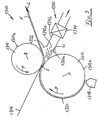
- the application device 110 is used for indirect, bilateral Applying liquid or pasty medium 120 or 120 'to one in Material web 116 moving in the direction of arrow L.
- the application device comprises 110 two application rollers 112 and 112 ', which with the material web 116 in the area of an order point S are in contact, as well as order works 118, 118 ', by means of which the application medium 120 or 120' onto the surfaces 112a, 112a 'of application rollers 112, 112' is applied.
- the application rollers rotate about their axes A, A 'in opposite directions to each other Arrows P and P ', respectively, so that this is applied to the roller surface Order medium 120 or 120 'is promoted to order point S.
- the layers of application media applied to the material web 116 are in Fig. 1 a with 120a or 120a '.
- the due to the film splitting effect remaining on the surfaces 112a and 112a 'of the application rollers 112, 112' Application medium layers are designated 120b and 120b 'in FIG. 1a.
- the steam generating and feeding device shown on the right in FIG. 1 a 122 comprises a steam supply line running in the transverse direction Q of the material web 116 124, one on its side facing the spray area Sp Has a plurality of openings 124a, from which the supplied in line 124 Steam D can escape undirected into the spray area Sp, which is shown in Fig. 1 a is indicated by three small arrows.
- over the steam supply line 124 only feeds as much steam into the spray area Sp, as a result of the movement of the material web 116 or the rotation of the Application roller 112 or due to other effects from this spray area Sp escapes.
- the steam generating and supplying device 222 ' can also include a slit nozzle body 224b 'that fits one having steam outlets 224a 'provided steam supply pipe 224' and with this glued, soldered, welded or in any other way leakproof connected is.
- the latter type of connection allows moving and rotating the nozzle, and adjusting the gap width of the nozzle.
- the fall arrester 126 comprises a catching surface 128, the one of which faces the material web 116 Towards the material web 116 in the opposite direction L, in such a way that its edge is about a distance from the material web 5 mm to 50 mm, preferably about 30 mm.
- a collecting container 130 At the bottom of the A collecting container 130 is provided, for example a collecting trough in which the application medium running off the catching surface 128 is located 120 'collects before it either goes through a drain line 132 is disposed of and disposed of in a waste container, or for reuse an application medium reservoir is supplied.
- a vacuum source 135 is connected to support the laxative effect be, which with appropriate dimensioning as a suction device can act, which sucks up the residual spray.
- a separators can the individual suctioned components be separated and reused.
- the application medium 120 typically has a temperature of the order of magnitude from 30 ° C to 60 ° C, so that there is also the risk of that the application medium 120 'impinging on the catching wall 128 dries up and "baked" on this catch wall 128. This would affect the trap 128 form a covering that would have to be removed from time to time.
- the catching surface 128, i.e. on the side of this catch surface facing away from the application point S are preferably on the outside of the catching surface 128, i.e. on the side of this catch surface facing away from the application point S, cooling fins 134 arranged, the heat exchange between the collecting device 126 and of the surrounding air.
- a Line 136 rinsing liquid preferably water, is fed to the catch surface 128 which the collecting medium 120 'striking the catching surface 128 washed and rinsed to the gutter 130.
- the collecting device 126 can be structurally simple and inexpensive be produced, for example, as a sheet metal structure.
- each type of Fluid which is the surface tension of the application medium reduces, quick drying of the application medium or the Formation of the application medium spray mist prevented or its disadvantageous Prevents effects on the order result.
- Alcohol be used as a fluid.
- the influence of the fluid on the Spray formation specifically changed by suitable choice of fluid temperature become.
- both high and low fluid temperatures can be used be beneficial.
- the core of the collecting device can be a simple construction Be a catch wall.
- One end of the trap wall facing the material web can be used for Material web run back and forth in the direction of travel. This allows the Balancing the impact of the application medium particles on the trap wall and thus reduces the risk of these particles being sprayed off the catch wall become.
- the catcher desirably, as close as possible to the web of material to arrange.
- a certain safety distance from the Material web are observed, especially with regard to the so-called Web flutter or a winding of the material web around it in the area of Ordering counter roll after a tear of the material web.
- the end of the trap wall facing the material web of this has a distance of between 5 mm and 10 mm.
- the Catch wall preferably on its surface facing away from the application point, is provided with cooling elements, for example cooling fins.
- cooling elements for example cooling fins.
- Passive cooling fins can also be provided for "active” cooling elements, for example cooling lines through which a cooling fluid flows.
- the collecting device is preferably at its lower end with a Collection basin designed for trapped application medium particles.
- the collecting device can also be attached at its lower end be provided with a sequence so that the collected or collected application medium can be disposed of easily.
- the drain can be connected to a vacuum source.
- a collecting device arranged below the material web can be moved over the beneficial effects on the uniformity of the layer application also contribute to the cleanliness of the entire application device, since with it too Due to gravity, the application medium splashing down is caught can be.
- a collecting device When applying on both sides of the material web, especially in the area of Ordering point of material web running essentially in the vertical direction, a collecting device can be arranged on each side of the material web.
- the design of the collecting device as a sheet metal construction is characterized by low production costs and easy to manufacture. Basically can the collecting device but also made of plastic or other suitable materials be made.
- the job can be adjacent, but in the running direction of the material web a suction device can be arranged behind the application, which not properly delivered to the material web in the manner of a vacuum cleaner or transferred particles of the application medium and / or not in the application layer sucks off persistent particles of the application medium.
- the suction device can, for example, a discharge line and one in the discharge line have arranged suction fan, wherein an inlet opening of the discharge line is arranged adjacent to the material web.
- an application device is generally designated 1110.
- the Application device 1110 is used for indirect application of a liquid or pasty medium 1120 on a material web moving in the direction of arrow L. 1116.
- the application device 1110 comprises an application roller 1112, which with the material web 1116 in the area of an order point S in Contact is made, as well as an order work 1118, by means of which the order medium 1120 is applied to the surface 1112a of the application roller 1112.
- the Application roller rotates in the direction of arrow P about its axis A, so that application medium 1120 applied to the application roller surface 1112a is promoted from order work 1118 to order point S.
- the material web 1116 is in the area of the application point S around a counter roller 1114, which runs in the opposite direction to the application roller 1112, i.e. in the direction arrow P 'is rotated about its axis B.
- the rollers 1112 and 1114 are rotated so that their surfaces 1112a and 1114a in the area of contact with the material web 1116 relative to this without slipping and slipping move.
- the layer of application medium applied to the material web 1116 is denoted by F in Figure 3.
- the material web 1116 comes in particular at high running speeds it after the order point S, in particular where the material web 1116 of of the surface 1112a of the application roller 1112 lifts up to form an application medium spray N.
- the application medium particles forming this spray mist N. 1120a can both still liquid or pasty droplets of application medium 1120 as well as already dried particles of Order medium 1120.
- a collecting device 1122 is arranged after the application point S.
- the Collecting device 1122 comprises a catching wall 1124 with one of the material webs adjacent end 1124a, one remote from web 1116 End 1124b and a rear wall 1124c, and side walls 1126, of which only a rough schematic is shown in FIG.
- the fall arrester 1122 is a sheet metal construction.
- the catching wall 1124 is bent in this way and connected to the side walls 1126 that the catcher 1122 the shape of a box open against the running direction L at 1122a having.
- the lower end wall of the collecting box 1122 shown in the Embodiment is formed by the lower end 1124b of the catching wall 1124, is designed as a collecting container 1128, in which the from the rear wall 1124c drain media 1120 collects before passing through a drain line 1130 is either directed to a waste container and disposed of or to the re-use is supplied to an application medium reservoir.
- a drain line 1130 can provide a vacuum source to assist the laxative effect 1131 connected.
- the application medium 1120 typically has a temperature of the order of magnitude has from 50 ° C to 60 ° C, there is a risk that the catch box 1122 during operation of the application device 1110 to these temperatures warmed up. In this case, that would be contained in the order medium 1120 Solvent, for example water, when it hits the collecting wall 1124 evaporate rapidly, and so the application medium 1120 on this catch wall 1124 dry completely. A covering would thus quickly form on the catching wall 1124, which should be removed from time to time. To one essentially maintenance-free operation of the collecting device 1122 are to be made possible preferably on the outside of the catch wall 1124, i.e.
- cooling fins 1132 attached to the Heat exchange between the applicator 1122 and that surrounding it Improve air.
- the cooling effect of these cooling fins Evaporation of the solvent of the application medium 1120 after its impact delayed on the catching wall 1124 so far that the application medium in essentially residue-free down the collecting wall 1124 into the collecting container 1128 is running.
- the upper end 1124a, the lower end 1124b and the rear wall 1124c of the catching wall 1124 also as separate box components can be trained. It is also possible that all parts of the Box are integrally formed with each other. It should also be noted that instead of the cooling fins 1132 also cooling lines through which cooling fluid flows the collecting box 1122 can be arranged.
- FIG. 4 shows an application device 1210 for applying a Application medium 1220 on a material web moving in the running direction L. 1216 shown.
- the application device 1210 comprises two application units 1218 and 1218 'together with assigned application rollers 1212 and 1212', respectively rotate in opposite directions about their axes A or A '(direction of arrows P or P') and so the order medium 1220 from the order works 1218, 1218 'to Promote material web 1216.
- This Spray N is collected by a collecting device 1222 or 1222 ' to prevent it from sticking to the layer applied to the material web F or F 'precipitates and adversely affects their quality.
- the Structure of the collecting devices 1222 and 1222 ' is based on the explanations of the collecting device 1122 according to FIG. 3.
- FIG. 5 shows a further embodiment of an application device.
- the application device 1310 comprises an application unit 1318, which application medium 1320 on the surface 1312a of an application roller 1312.
- the Application roller 1312 rotates about its axis A in the direction of arrow P, so that the order medium 1320 is conveyed from the order work 1318 to an order point S. where it is on a web of material moving in the direction of arrow L. 1316 is applied.
- the material web 1316 is in the area of the order point led around a counter roller 1314, which rotates about its axis B opposite to the application roller 1312, i.e. turns in the direction of arrow P '.
- the suction device 1340 includes a discharge line 1342, the opening 1342a of the job site S is adjacent and is arranged facing this.
- a suction fan 1344 is arranged, which in the area of the inlet opening 1342a generates such a suction that the application medium particles 1320a of the spray M from the suction device 1340 in the manner of a vacuum cleaner are sucked in and therefore no longer on the application layer F can reach.
- a can be located at the inlet opening 1342a Collection device 1322 may be arranged, the advantages of which on the basis of the exemplary embodiment 3 have been explained above. With appropriate However, suction power of the suction fan 1344 can be such Collection device 1322 can also be dispensed with.
Landscapes
- Coating Apparatus (AREA)
- Paper (AREA)
- Application Of Or Painting With Fluid Materials (AREA)
Description
- Fig. 1a
- eine erfindungsgemäße Auftragsvorrichtung zum beidseitigem Auftragen einer Auftragsmediumschicht auf eine Materialbahn, wobei den beiden Auftragsseiten der Materialbahn zwei verschiedene Ausführungsformen erfindungsgemäßer Dampferzeugungs- und -zuführvorrichtungen zugeordnet sind;
- Fig. 1b
- eine abgewandelte Ausführungsform der in Fig. 1a links dargestellten Dampferzeugungs- und -zuführvorrichtung; und
- Fig. 2a und 2b
- Ansichten einer Auftragsvorrichtung gemäß dem Stand der Technik.
- Figur 3
- eine grobschematische Seitenansicht einer Auftragsvorrichtung mit Auffangvorrichtung;
- Figur 4
- eine grobschematische Seitenansicht einer Vorrichtung zum beidseitigen Bestreichen einer Materialbahn mit entsprechend beidseitig vorgesehenen Auffangvorrichtungen; und
- Figur 5
- eine grobschematische Seitenansicht einer Auftragsvorrichtung mit Saugvorrichtung.
Claims (20)
- Vorrichtung (110) zum Auftragen eines flüssigen oder pastösen Auftragsmediums (120; 120') auf eine laufende Materialbahn (116), insbesondere aus Papier oder Karton,dadurch gekennzeichnet, daß der Auftragsstelle (S) bzw. der Rakelstelle benachbart, jedoch in Laufrichtung (L) der Materialbahn (116) hinter der Auftragsstelle (S) bzw. der Rakelstelle eine Vorrichtung (122; 122') zum Erzeugen und Zuführen von Dampf, vorzugsweise Wasserdampf, vorgesehen ist.wobei ein Auftragswerk (118; 118') das Auftragsmedium (120; 120') zunächst auf ein Auftragselement (112; 112'), bspw. eine Auftragswalze, aufbringt, welches das Auftragsmedium (120; 120') dann an einer Auftragsstelle (S) an die Materialbahn (116) als Auftragsschicht (120a; 120a') überträgt, oder in einen zwischen der Materialbahn und einem Begrenzungselement, bspw. einer Begrenzungswalze, gebildeten Auftragssumpf einbringt, in welchem das Auftragsmedium sich als Auftragsschicht auf der Materialbahn niederschlägt,wobei gewünschtenfalls ferner an einer in Laufrichtung der Materialbahn hinter der Auftragsstelle angeordneten Rakelstelle eine Rollrakeleinrichtung zum Egalisieren oder/und Dosieren der Auftragsschicht angeordnet ist,
- Vorrichtung nach Anspruch 1,
dadurch gekennzeichnet, daß die Dampferzeugungs- und -zuführvorrichtung (122; 122') das Dampf in Richtung auf die Auftragsstelle (S) bzw. die Rakelstelle hin abgibt. - Vorrichtung nach Anspruch 1 oder 2,
dadurch gekennzeichnet, daß die Dampferzeugungs- und -zuführvorrichtung (122; 122') eine Dampfzuführleitung 124; 124') umfaßt, welche im Bereich der Auftragsvorrichtung (110; 110') zumindest auf ihrer der Auftragsstelle (S) bzw. der Rakelstelle zugewandten Seite wenigstens eine Dampfaustrittsöffnung (124a; 124b') aufweist. - Vorrichtung nach Anspruch 3,
dadurch gekennzeichnet, daß die Dampfaustrittsöffnung (124b') bildende Wandungsabschnitte der Dampfzuführleitung (124') bzw. der Dampfaustrittsöffnung (224a') in Dampfströmrichtung nachgeordnete Wandungsabschnitte (224b') düsenartig, vorzugsweise sich in Dampfströmrichtung verjüngend, ausgebildet sind. - Vorrichtung nach einem der Ansprüche 1 bis 4,
dadurch gekennzeichnet, daß die Dampferzeugungs- und -zuführvorrichtung (122'; 222') als Rückdrängeinheit ausgebildet ist. - Vorrichtung nach einem der Ansprüche 1 bis 5,
dadurch gekennzeichnet, daß auf der der Auftragsstelle (S) bzw. der Rakelstelle abgewandten Seite der Dampferzeugungs- und -zuführvorrichtung (122') eine Auffangvorrichtung (126) für nicht ordnungsgemäß an die Materialbahn (116) abgegebene Auftragsmediumtröpfchen bzw. -partikel (N) oder/und nicht in der Auftragsschicht (120a') verharrende Auftragsmediumtröpfchen bzw. -partikel (N) angeordnet ist. - Vorrichtung nach Anspruch 6,
dadurch gekennzeichnet, daß einer Fangfläche (128) der Auffangvorrichtung (126) eine Kühlvorrichtung (134), beispielsweise in Form von Kühlrippen oder/und einer Kühlschlange oder/und eines Wärmetauschers, zugeordnet ist. - Vorrichtung nach Anspruch 6 oder 7,
dadurch gekennzeichnet, daß einer Fangfläche (128) der Auffangvorrichtung (126) eine Vorrichtung (136) zum Zuführen von Spülflüssigkeit zugeordnet ist. - Vorrichtung nach einem der Ansprüche 1 bis 8,
dadurch gekennzeichnet, daß auf der der Auftragsstelle (S) bzw. der Rakelstelle abgewandten Seite der Dampferzeugungs- und -zuführvorrichtung (122') eine Saugvorrichtung (135) zum Absaugen der Dampfatmosphäre oder/und zum Absaugen von nicht ordungsgemäß an die Materialbahn (116) abgegebenen Auftragsmediumtröpfchen bzw. -partikeln (N) oder/und nicht in der Auftragsschicht (120a') verharrenden Auftragsmediumtröpfchen bzw. -partikeln (N) angeordnet ist. - Vorrichtung nach einem der Ansprüche 1 bis 9,
dadurch gekennzeichnet, daß bei beidseitigem Auftrag auf die Materialbahn (116) beidseits der Materialbahn (116) jeweils eine Dampferzeugungs- und -zuführvorrichtung (122, 122') angeordnet ist. - Vorrichtung nach einem der Ansprüche 1 bis 10,
dadurch gekennzeichnet, daß eine Mehrzahl von in Querrichtung der Materialbahn (116) aufeinanderfolgend angeordneter Dampferzeugungs- und-zuführabschnitten vorgesehen ist, welche zumindest hinsichtlich der von ihnen pro Zeiteinheit abgegebenen Dampfmenge unabhängig voneinander steuerbar sind. - Verfahren zum Auftragen eines flüssigen oder pastösen Auftragsmediums (120; 120') auf eine laufende Materialbahn (116), insbesondere aus Papier oder Karton, unter Verwendung einer Vorrichtung nach einem der Ansprüche 1 bis 11,dadurch gekennzeichnet, daß man einem der Auftragsstelle (S) bzw. der Rakelstelle benachbarten, jedoch in Laufrichtung (L) der Materialbahn (116) hinter der Auftragsstelle (S) bzw. der Rakelstelle angeordneten Spritzbereich Dampf, vorzugsweise Wasserdampf, zuführt und in diesem Bereich den Dampf, vorzugsweise den Wasserdampf, erzeugt.bei welchem das Auftragsmedium (120; 120') zunächst mittels eines Auftragswerks (118; 118') auf ein Auftragselement (112; 112'), bspw. eine Auftragswalze, aufgebracht wird, von welchem das Auftragsmedium (120; 120') dann an einer Auftragsstelle (S) an die Materialbahn (116) als Auftragsschicht (120a; 120a') übertragen wird, oder in einen zwischen der Materialbahn und einem Begrenzungselement, bspw. einer Begrenzungswalze, gebildeten Auftragssumpf eingebracht wird, in welchem sich das Auftragsmedium als Auftragsschicht auf der Materialbahn niederschlägt,wobei die Auftragsschicht gewünschtenfalls an einer in Laufrichtung der Materialbahn hinter der Auftragsstelle angeordneten Rakelstelle egalisiert oder/und dosiert wird,
- Verfahren nach Anspruch 12,
dadurch gekennzeichnet, daß Dampf in Richtung auf die Auftragsstelle (S) bzw. die Rakelstelle hin abgegeben wird. - Verfahren nach Anspruch 12 oder 13,
dadurch gekennzeichnet, daß Dampf über eine Dampfzuführleitung (124; 124') zugeführt wird, welche im Bereich der Auftragsvorrichtung (110) zumindest auf ihrer der Auftragsstelle (S) bzw. der Rakelstelle zugewandten Seite wenigstens eine Dampfaustrittsöffnung (124a; 124a') aufweist. - Verfahren nach einem der Ansprüche 12 bis 14,
dadurch gekennzeichnet, daß man den Spritz- bzw. Dampfabführungsbereich (Sp) derart ausbildet, daß die Dampfatmosphäre aus diesem Bereich mit einem Strömungsverlauf oder/und einer Strömungsgeschwindigkeit abströmt, daß zumindest ein Teil der etwaig im Bereich der Auftragsstelle (S) bzw. der Rakelstelle gebildeten Auftragsmediumtröpfchen bzw. -partikel (N) in die Auftragsmediumschicht (120a') zurückgedrängt wird. - Verfahren nach einem der Ansprüche 12 bis 15,
dadurch gekennzeichnet, daß nicht ordungsgemäß an die Materialbahn (116) abgegebene Auftragsmediumtröpfchen bzw. -partikel (N) oder/und nicht in der Auftragsschicht (120a') verharrende Auftragsmediumtröpfchen bzw. -partikel (N) mittels einer Auffangvorrichtung (126) aufgefangen werden. - Verfahren nach Anspruch 16,
dadurch gekennzeichnet, daß eine Fangfläche (128) der Auffangvorrichtung (126) gekühlt wird. - Verfahren nach Anspruch 16 oder 17,
dadurch gekennzeichnet, daß eine Fangfläche (128) der Auffangvorrichtung (126) mittels einer Flüssigkeit gespült wird. - Verfahren nach einem der Ansprüche 12 bis 18,
dadurch gekennzeichnet, daß die Dampfatmosphäre oder/und nicht ordnungsgemäß an die Materialbahn abgegebene Auftragsmediumtröpfchen bzw. -partikel (N) oder/und nicht in der Auftragsschicht (120a') verharrende Auftragsmediumtröpfchen bzw. -partikel (N) mittels einer Saugvorrichtung (135) abgesaugt werden. - Verfahren nach einem der Ansprüche 12 bis 19,
dadurch gekennzeichnet, daß der Materialbahn (116) in einer Mehrzahl von in Querrichtung (Q) der Materialbahn (116) aufeinanderfolgend angeordneten Abschnitten Dampf zugeführt wird, wobei die von dieser Mehrzahl von Abschnitten pro Zeiteinheit abgegebene Dampfmengen unabhängig voneinander einstellbar sind.
Applications Claiming Priority (2)
| Application Number | Priority Date | Filing Date | Title |
|---|---|---|---|
| DE19800955A DE19800955A1 (de) | 1998-01-13 | 1998-01-13 | Vorrichtung zum Auftragen eines flüssigen oder pastösen Auftragsmediums auf eine laufende Materialbahn, insbesondere aus Papier oder Karton |
| DE19800955 | 1998-01-13 |
Publications (2)
| Publication Number | Publication Date |
|---|---|
| EP0930397A1 EP0930397A1 (de) | 1999-07-21 |
| EP0930397B1 true EP0930397B1 (de) | 2001-11-07 |
Family
ID=7854465
Family Applications (1)
| Application Number | Title | Priority Date | Filing Date |
|---|---|---|---|
| EP98123200A Expired - Lifetime EP0930397B1 (de) | 1998-01-13 | 1998-12-05 | Vorrichtung und Verfahren zum Auftragen eines flüssigen oder pastösen Auftragsmediums auf eine laufende Materialbahn, insbesondere aus Papier oder Karton |
Country Status (5)
| Country | Link |
|---|---|
| US (2) | US6171653B1 (de) |
| EP (1) | EP0930397B1 (de) |
| JP (1) | JPH11256500A (de) |
| AT (1) | ATE208449T1 (de) |
| DE (2) | DE19800955A1 (de) |
Families Citing this family (25)
| Publication number | Priority date | Publication date | Assignee | Title |
|---|---|---|---|---|
| DE19800954A1 (de) * | 1998-01-13 | 1999-07-15 | Voith Sulzer Papiertech Patent | Vorrichtung zum direkten oder indirekten Auftragen eines flüssigen oder pastösen Auftragsmediums auf eine laufende Materialbahn, insbesondere aus Papier oder Karton |
| US6977011B2 (en) | 1999-06-18 | 2005-12-20 | Voith Paper Patent Gmbh | Roller provided for use in coating machines |
| DE10238764A1 (de) * | 2002-08-23 | 2004-03-04 | Voith Paper Patent Gmbh | Auftragsvorrichtung mit mindestens einer nach dem Heatpipe-Prinzip kühlbaren, der Umgebungsluft ausgesetzten Oberfläche in Zuordnung zu wenigstens einem Auftragswerk |
| US6869639B2 (en) * | 2002-09-30 | 2005-03-22 | Stora Enso North America Corp. | Film coater and smoothing method and apparatus |
| DE10260847A1 (de) * | 2002-12-23 | 2004-07-01 | Voith Paper Patent Gmbh | Verfahren zur Herstellung und/oder Behandlung einer Materialbahn |
| DE10311993A1 (de) | 2003-03-19 | 2004-10-14 | Voith Paper Patent Gmbh | Verfahren zur Behandlung einer Faserstoffbahn |
| DE10333950A1 (de) * | 2003-07-25 | 2005-02-10 | Voith Paper Patent Gmbh | Verfahren zum ein- oder beidseitigen Auftragen von flüssigem bis pastösem Auftragsmedium |
| US7634860B2 (en) * | 2004-05-03 | 2009-12-22 | Transphase Technology, Ltd. | Steam box |
| DE102004022489A1 (de) * | 2004-05-07 | 2005-12-01 | Voith Paper Patent Gmbh | Pressenanordnung und Verfahren zum einseitigen oder beidseitigen Behandeln einer laufenden Materialbahn |
| DE102004047238A1 (de) * | 2004-09-29 | 2006-04-13 | Voith Paper Patent Gmbh | Auftragsvorrichtung |
| DE102005062527A1 (de) * | 2005-12-16 | 2007-06-21 | Gebr. Schmid Gmbh & Co. | Vorrichtung und Verfahren zur Oberflächenbehandlung von Substraten |
| CA2676814C (en) | 2007-03-23 | 2014-08-12 | Megtec Systems, Inc. | Web coating applicator with cooling and material recovery |
| DE102007027817A1 (de) * | 2007-06-13 | 2008-12-18 | Voith Patent Gmbh | Rakelvorrichtung |
| JP2010540237A (ja) * | 2007-10-05 | 2010-12-24 | ビーエーエスエフ ソシエタス・ヨーロピア | 亜鉛メッキ鋼板を酸性ポリマーの水性製剤で塗装する方法 |
| DE102009026863A1 (de) | 2009-06-09 | 2010-12-16 | Voith Patent Gmbh | Vorrichtung und Verfahren zum Auftragen eines flüssigen oder pastösen Mediums auf eine Materialbahn |
| FI123582B (fi) * | 2010-04-29 | 2013-07-31 | Metso Paper Inc | Menetelmä ja laitteisto kuiturainan käsittelemiseksi |
| EP2647761A1 (de) * | 2012-04-02 | 2013-10-09 | Metso Paper Inc. | Verfahren zur Beeinflussung der hydrophoben Eigenschaften eines Fasernetzes in Zusammenhang mit der Herstellung des Fasernetzes und Herstellungsverfahren für das Fasernetz und Vorrichtung zur Anwendung einer hydrophoben Klebchemikalie für das Fasernetz |
| US20140319241A1 (en) * | 2013-04-30 | 2014-10-30 | Armstrong World Industries, Inc. | System and method for humidifying a system for applying a coating to a workpiece |
| WO2021262506A1 (en) | 2020-06-26 | 2021-12-30 | Armstrong World Industries, Inc. | Coating humidification system |
| CN111921742A (zh) * | 2020-07-23 | 2020-11-13 | 安徽春江保温建材科技有限公司 | 一种保温板加工用涂胶装置 |
| DE102021113146B3 (de) | 2021-05-20 | 2022-10-06 | Voith Patent Gmbh | Entnebelungsvorrichtung und Verwendung |
| CN115518818B (zh) * | 2022-10-09 | 2023-10-13 | 南通中邦纺织科技有限公司 | 一种防水抗静电多功能混纺面料生产设备及其制备方法 |
| KR20250158808A (ko) * | 2023-03-16 | 2025-11-06 | 필립모리스 프로덕츠 에스.에이. | 시트 재료에 액체 도포하기 위한 장치 및 방법 |
| CN116590958B (zh) * | 2023-05-18 | 2024-08-16 | 新郑市吉龙包装材料有限公司 | 一种包装铝箔纸的涂布设备 |
| DE102024105969A1 (de) * | 2024-03-01 | 2025-09-04 | Voith Patent Gmbh | Auftragswerk |
Family Cites Families (10)
| Publication number | Priority date | Publication date | Assignee | Title |
|---|---|---|---|---|
| US3152918A (en) * | 1961-06-02 | 1964-10-13 | Kimberly Clark Co | Process of coating paper with a trailing blade |
| DE1817912C3 (de) * | 1968-11-22 | 1978-08-17 | Vepa Ag, Riehen B. Basel (Schweiz) | Vorrichtung zum kontinuierlichen Aufbringen einer Behandlungsflüssigkeit, insbesondere einer Färbeflüssigkeit, auf ein bahnförmiges Textilgut o.dgl |
| SE419946B (sv) * | 1974-10-16 | 1981-09-07 | Inventing Ab | Sett och anordning for bestrykning av en lopande bana |
| DE3701406A1 (de) * | 1987-01-20 | 1988-07-28 | Vib Apparatebau Gmbh | Vorrichtung zum aufbringen von dampf auf eine materialbahn, wie papier |
| US5106655A (en) * | 1989-01-27 | 1992-04-21 | Measurex Corporation | Cross-directional smoothness controller and method of using the same |
| DE3935059C1 (de) * | 1989-10-20 | 1991-02-21 | Juergen 8609 Bischberg De Ruemmer | |
| DE4224726A1 (de) * | 1992-07-27 | 1994-02-03 | Voith Gmbh J M | Streicheinrichtung mit zwischen einer Auftragswalze und einer Gegenwalze gebildetem Auftragsspalt |
| FI925704L (fi) * | 1992-12-15 | 1994-06-16 | Valmet Paper Machinery Inc | Menetelmä ja laitteisto telan pinnan päällystämiseksi |
| FI93242C (fi) * | 1993-03-25 | 1995-03-10 | Valmet Paper Machinery Inc | Menetelmä ja laitteisto päällystysleveyden rajoittamiseksi ja/tai telapäätyjen vaurioitumisen estämiseksi paperin tai vastaavan rainamateriaalin päällystyksessä tai pintaliimauksessa |
| DE29621877U1 (de) * | 1996-12-17 | 1997-02-13 | Voith Sulzer Papiermaschinen GmbH, 89522 Heidenheim | Auftrags- und Dosiersystem zum Auftragen eines Streichmediums auf Auftragswalzen |
-
1998
- 1998-01-13 DE DE19800955A patent/DE19800955A1/de not_active Withdrawn
- 1998-12-05 DE DE59802049T patent/DE59802049D1/de not_active Expired - Lifetime
- 1998-12-05 AT AT98123200T patent/ATE208449T1/de not_active IP Right Cessation
- 1998-12-05 EP EP98123200A patent/EP0930397B1/de not_active Expired - Lifetime
-
1999
- 1999-01-08 US US09/229,090 patent/US6171653B1/en not_active Expired - Fee Related
- 1999-01-13 JP JP11006959A patent/JPH11256500A/ja active Pending
-
2000
- 2000-06-28 US US09/605,310 patent/US6444030B1/en not_active Expired - Fee Related
Also Published As
| Publication number | Publication date |
|---|---|
| DE19800955A1 (de) | 1999-07-15 |
| JPH11256500A (ja) | 1999-09-21 |
| US6444030B1 (en) | 2002-09-03 |
| ATE208449T1 (de) | 2001-11-15 |
| US6171653B1 (en) | 2001-01-09 |
| DE59802049D1 (de) | 2001-12-13 |
| EP0930397A1 (de) | 1999-07-21 |
Similar Documents
| Publication | Publication Date | Title |
|---|---|---|
| EP0930397B1 (de) | Vorrichtung und Verfahren zum Auftragen eines flüssigen oder pastösen Auftragsmediums auf eine laufende Materialbahn, insbesondere aus Papier oder Karton | |
| DE102022105518B4 (de) | Auftragsdüse, Auftragswerk und Verfahren | |
| DE19800954A1 (de) | Vorrichtung zum direkten oder indirekten Auftragen eines flüssigen oder pastösen Auftragsmediums auf eine laufende Materialbahn, insbesondere aus Papier oder Karton | |
| EP0955408A2 (de) | Verfahren und Vorrichtung zum Aufbringen eines Auftragsmediums auf einen laufenden Untergrund | |
| EP0670004B1 (de) | Verfahren und einrichtung zum beschichten einer laufenden warenbahn | |
| DE10012344A1 (de) | Vorhang-Auftragsverfahren | |
| DE102022105510B4 (de) | Auftragsdüse, Auftragswerk und Verfahren | |
| DE202017100655U1 (de) | Vorrichtung zur Behandlung von Faserbahnen | |
| DE69323214T2 (de) | Vorrichtung und verfahren zur minimierung von beschichtungslücken auf einer papierbahn | |
| EP1544353B1 (de) | Vorhang-Auftragsvorrichtung | |
| DE10012345A1 (de) | Vorhang-Auftragsvorrichtung | |
| EP1198643B1 (de) | Auftragsvorrichtung | |
| DE10057734A1 (de) | Vorhang-Auftragsvorrichtung | |
| DE2263714C3 (de) | Vorrichtung zum Dosieren von Beschichtungen auf bahnförmigen Materialien | |
| DE19733333A1 (de) | Vorrichtung zum direkten oder indirekten Auftragen eines flüssigen oder pastösen Auftragsmediums auf eine laufende Materialbahn, insbesondere aus Papier oder Karton | |
| DE10057731A1 (de) | Vorhang-Auftragsvorrichtung | |
| EP1801289A1 (de) | Verfahren und Vorrichtung zum Auftragen eines Auftragsmediums auf eine Materialbahn | |
| EP1432525B1 (de) | Auftragsvorrichtung | |
| DE102005036667A1 (de) | Auftragsverfahren | |
| DE19707031C2 (de) | Vorrichtung zum Auftragen einer Schutzflüssigkeit auf Glas | |
| DE19960772A1 (de) | Auftragsverfahren | |
| EP1209274A2 (de) | Vorhang-Auftragsvorrichtung | |
| DE10125376A1 (de) | Auftragsvorrichtung | |
| EP1538263A1 (de) | Beschichtungsvorrichtung | |
| DE102006019788A1 (de) | Vorhang-Auftragswerk |
Legal Events
| Date | Code | Title | Description |
|---|---|---|---|
| PUAI | Public reference made under article 153(3) epc to a published international application that has entered the european phase |
Free format text: ORIGINAL CODE: 0009012 |
|
| AK | Designated contracting states |
Kind code of ref document: A1 Designated state(s): AT DE FI FR IT SE |
|
| AX | Request for extension of the european patent |
Free format text: AL;LT;LV;MK;RO;SI |
|
| 17P | Request for examination filed |
Effective date: 20000121 |
|
| AKX | Designation fees paid |
Free format text: AT DE FI FR IT SE |
|
| RAP1 | Party data changed (applicant data changed or rights of an application transferred) |
Owner name: VOITH PAPER PATENT GMBH |
|
| GRAG | Despatch of communication of intention to grant |
Free format text: ORIGINAL CODE: EPIDOS AGRA |
|
| GRAG | Despatch of communication of intention to grant |
Free format text: ORIGINAL CODE: EPIDOS AGRA |
|
| GRAH | Despatch of communication of intention to grant a patent |
Free format text: ORIGINAL CODE: EPIDOS IGRA |
|
| 17Q | First examination report despatched |
Effective date: 20010404 |
|
| GRAH | Despatch of communication of intention to grant a patent |
Free format text: ORIGINAL CODE: EPIDOS IGRA |
|
| GRAA | (expected) grant |
Free format text: ORIGINAL CODE: 0009210 |
|
| AK | Designated contracting states |
Kind code of ref document: B1 Designated state(s): AT DE FI FR IT SE |
|
| PG25 | Lapsed in a contracting state [announced via postgrant information from national office to epo] |
Ref country code: IT Free format text: LAPSE BECAUSE OF FAILURE TO SUBMIT A TRANSLATION OF THE DESCRIPTION OR TO PAY THE FEE WITHIN THE PRESCRIBED TIME-LIMIT;WARNING: LAPSES OF ITALIAN PATENTS WITH EFFECTIVE DATE BEFORE 2007 MAY HAVE OCCURRED AT ANY TIME BEFORE 2007. THE CORRECT EFFECTIVE DATE MAY BE DIFFERENT FROM THE ONE RECORDED. Effective date: 20011107 Ref country code: FR Free format text: LAPSE BECAUSE OF FAILURE TO SUBMIT A TRANSLATION OF THE DESCRIPTION OR TO PAY THE FEE WITHIN THE PRESCRIBED TIME-LIMIT Effective date: 20011107 |
|
| REF | Corresponds to: |
Ref document number: 208449 Country of ref document: AT Date of ref document: 20011115 Kind code of ref document: T |
|
| PG25 | Lapsed in a contracting state [announced via postgrant information from national office to epo] |
Ref country code: AT Free format text: LAPSE BECAUSE OF NON-PAYMENT OF DUE FEES Effective date: 20011205 |
|
| REF | Corresponds to: |
Ref document number: 59802049 Country of ref document: DE Date of ref document: 20011213 |
|
| EN | Fr: translation not filed | ||
| PLBE | No opposition filed within time limit |
Free format text: ORIGINAL CODE: 0009261 |
|
| STAA | Information on the status of an ep patent application or granted ep patent |
Free format text: STATUS: NO OPPOSITION FILED WITHIN TIME LIMIT |
|
| 26N | No opposition filed | ||
| PGFP | Annual fee paid to national office [announced via postgrant information from national office to epo] |
Ref country code: FI Payment date: 20111214 Year of fee payment: 14 |
|
| PGFP | Annual fee paid to national office [announced via postgrant information from national office to epo] |
Ref country code: DE Payment date: 20111222 Year of fee payment: 14 |
|
| PGFP | Annual fee paid to national office [announced via postgrant information from national office to epo] |
Ref country code: SE Payment date: 20120120 Year of fee payment: 14 |
|
| PG25 | Lapsed in a contracting state [announced via postgrant information from national office to epo] |
Ref country code: SE Free format text: LAPSE BECAUSE OF NON-PAYMENT OF DUE FEES Effective date: 20121206 |
|
| PG25 | Lapsed in a contracting state [announced via postgrant information from national office to epo] |
Ref country code: FI Free format text: LAPSE BECAUSE OF NON-PAYMENT OF DUE FEES Effective date: 20121205 |
|
| PG25 | Lapsed in a contracting state [announced via postgrant information from national office to epo] |
Ref country code: DE Free format text: LAPSE BECAUSE OF NON-PAYMENT OF DUE FEES Effective date: 20130702 |
|
| REG | Reference to a national code |
Ref country code: DE Ref legal event code: R119 Ref document number: 59802049 Country of ref document: DE Effective date: 20130702 |