EP0928958A2 - Umhüllte thermoelektrische Lanze zum Messen der Temperatur in einer Metallschmelze - Google Patents
Umhüllte thermoelektrische Lanze zum Messen der Temperatur in einer Metallschmelze Download PDFInfo
- Publication number
- EP0928958A2 EP0928958A2 EP99300099A EP99300099A EP0928958A2 EP 0928958 A2 EP0928958 A2 EP 0928958A2 EP 99300099 A EP99300099 A EP 99300099A EP 99300099 A EP99300099 A EP 99300099A EP 0928958 A2 EP0928958 A2 EP 0928958A2
- Authority
- EP
- European Patent Office
- Prior art keywords
- protective sheath
- layers
- molten metals
- thermocouple
- measuring
- Prior art date
- Legal status (The legal status is an assumption and is not a legal conclusion. Google has not performed a legal analysis and makes no representation as to the accuracy of the status listed.)
- Withdrawn
Links
Images


Classifications
-
- G—PHYSICS
- G01—MEASURING; TESTING
- G01K—MEASURING TEMPERATURE; MEASURING QUANTITY OF HEAT; THERMALLY-SENSITIVE ELEMENTS NOT OTHERWISE PROVIDED FOR
- G01K7/00—Measuring temperature based on the use of electric or magnetic elements directly sensitive to heat ; Power supply therefor, e.g. using thermoelectric elements
- G01K7/02—Measuring temperature based on the use of electric or magnetic elements directly sensitive to heat ; Power supply therefor, e.g. using thermoelectric elements using thermoelectric elements, e.g. thermocouples
-
- G—PHYSICS
- G01—MEASURING; TESTING
- G01K—MEASURING TEMPERATURE; MEASURING QUANTITY OF HEAT; THERMALLY-SENSITIVE ELEMENTS NOT OTHERWISE PROVIDED FOR
- G01K1/00—Details of thermometers not specially adapted for particular types of thermometer
- G01K1/08—Protective devices, e.g. casings
- G01K1/12—Protective devices, e.g. casings for preventing damage due to heat overloading
- G01K1/125—Protective devices, e.g. casings for preventing damage due to heat overloading for siderurgical use
-
- G—PHYSICS
- G01—MEASURING; TESTING
- G01K—MEASURING TEMPERATURE; MEASURING QUANTITY OF HEAT; THERMALLY-SENSITIVE ELEMENTS NOT OTHERWISE PROVIDED FOR
- G01K1/00—Details of thermometers not specially adapted for particular types of thermometer
- G01K1/08—Protective devices, e.g. casings
-
- G—PHYSICS
- G01—MEASURING; TESTING
- G01K—MEASURING TEMPERATURE; MEASURING QUANTITY OF HEAT; THERMALLY-SENSITIVE ELEMENTS NOT OTHERWISE PROVIDED FOR
- G01K1/00—Details of thermometers not specially adapted for particular types of thermometer
- G01K1/08—Protective devices, e.g. casings
- G01K1/10—Protective devices, e.g. casings for preventing chemical attack
- G01K1/105—Protective devices, e.g. casings for preventing chemical attack for siderurgical use
-
- H—ELECTRICITY
- H10—SEMICONDUCTOR DEVICES; ELECTRIC SOLID-STATE DEVICES NOT OTHERWISE PROVIDED FOR
- H10N—ELECTRIC SOLID-STATE DEVICES NOT OTHERWISE PROVIDED FOR
- H10N10/00—Thermoelectric devices comprising a junction of dissimilar materials, i.e. devices exhibiting Seebeck or Peltier effects
- H10N10/80—Constructional details
Definitions
- the present invention relates to a thermocouple lance with a protective sheath suitable for measuring relatively high temperatures in molten metal baths of steel or the like.
- thermocouples made from wires of Pt-Rh alloy relatively high in melting point and stable in the atmosphere, the wires being fitted in a tubular sheath of aluminosilicate fibers.
- the prior thermocouples are currently expensive as well as less in the life expectancy of repetitive use because they are apt to become impossible of accurate temperature measurement and thus have to be disposed after only one or twice measuring works in the molten steel bath.
- thermocouples has W-Re alloy wires that are enveloped in the metallic protective tubular sheath made of, for example, stainless steel so as to be adapted for use in high temperatures.
- Any type of the thermocouples with stainless steel protective sheaths has been designed to be used in the atmosphere of above 1000 °C.
- This protective sheath is usually produced from a special heat resisting alloy of, for example, Inconel which is a nickel-base alloy including chrome and iron.
- Another type of the prior thermocouples is well known in which the Pt-Rh wires are encapsulated in the protective tube of cermet.
- the sheathed thermocouple assembly includes therein an alumel-chromel thermocouple consisting of two wires of different metals, or alumel and chromel.
- the two wires are contained in the stainless steel sheath together with inorganic insulating material in an electrically insulated relation from each other and further hermetically sealed at the open end of the sheath by means of the plug.
- the plug is provided in a ceramic end plate thereof with two tubes, which are made of Kovar, or iron-nickel-cobalt alloy, and coated on the inner surfaces thereof with electrically insulating sleeves.
- the two wires extend outside the sheath through tubes with no direct contact with their associated tubes.
- the thermal shock resistance of the cermet-made protective sheath is 1.5 times of that of the Si 3 N 4 -made protective sheath.
- the Si 3 N 4 -made protective sheath when directly immersed into the molten steel bath above 1700 °C, may crack in a relatively short interval of immersion with resulting in break of the sheath.
- thermocouple may not be used in inert-gas atmosphere and its permissible temperature limit in environmental atmosphere is at 1500°C.
- the W-Re thermocouple may be used in any of inert-gas atmosphere and environmental atmosphere and its permissible temperature limit is at 400 °C in environmental atmosphere while at 2300°C in inert-gas atmosphere.
- the Pt-Rh thermocouple of platinum-rhodium alloy wires has usually the thermo-electromotive force that is 1/15 timesof that of the alumel-chromel thermocouple while 1/7 times of that of the W-Re thermocouple.
- the Pt-Rh thermocouple has a shortcoming which is inferior in accuracy as well as rapid response of the temperature measurement as compared with the other types of the thermocouple.
- thermocouples have further disadvantage in which they are apt to be stained with molten metals so as to be deteriorated in rapid response of temperature measurement. This causes a collateral problem in which troublesome process is inevitably required to remove iron or steel stains from the Pt-Rh alloy wires and protective sheath of the thermocouple assembly.
- Another problem faced in the concurrently used thermocouples is in need of frequent replacement of the thermocouples because they are apt to become impossible of accurate temperature measurement after only one or twice measuring works in the molten steel bath. It is to be understood that the W-Re alloy wires for the thermocouples tend to be subjected to oxidation in environmental atmosphere so that it is not permitted to use for measuring high temperatures in the molten iron for casting.
- the outer protective sheath is also disadvantageously apt to be stained with molten metals.
- thermocouple lance for measuring high temperatures in molten metal baths, which comprises a thermocouple consisting of tungsten-rhenium alloy wires, and a protective sheath of layered structure consisting of cermet layers having a matrix of a substance, or molybdenum, hard to be subjected to reaction with molten metals, and other layers high in thermal shock, chemical reaction and mechanical shock resistances to molten metals.
- a thermocouple lance for measuring high temperatures in molten metal baths, which comprises a thermocouple consisting of tungsten-rhenium alloy wires, and a protective sheath of layered structure consisting of cermet layers having a matrix of a substance, or molybdenum, hard to be subjected to reaction with molten metals, and other layers high in thermal shock, chemical reaction and mechanical shock resistances to molten metals.
- thermocouple lance for measuring high temperatures in molten metal baths, which has a protective sheath of layered structure, each layer of which includes therein filaments of heat resisting property, the filaments being arranged in the circumferential direction of the protective sheath, or in a direction along which may occur a thermal stress and a tensile stress, to thereby provide the sufficient thermal shock resistance for the protective sheath and also to provide the life expectancy of repetitive measuring services.
- a further aim of the present invention is to provide a thermocouple lance for measuring temperatures in molten metals, comprising a protective sheath with one closed end and one open end wherein a filler and a pair of temperature-measuring alloy wires are contained, the temperature-measuring alloy wires being composed of two wires of different alloys joined with each other at their confronting ends to form a junction where the temperature is to be measured, and the protective sheath being formed in a multi-layered structure of layers different in composition and laid concentrically one on top of another in alternate layer.
- thermocouple lance having the wires kept hermetically from the atmosphere is endurablein heat resistance to the temperature in the molten steel bath for the steel making.
- Another aim of the present invention is to provide a thermocouple lance for measuring temperatures in molten metals, wherein the layered structure of the protective sheath is made from the layers of a molybdenum matrix, and other layers of at least one selected from the class consisting of C, MgO, CaO, Al 2 O 3 and ZrO 2 , the filler is of porous heat-resisting ceramics, and the protective sheath is hermetically closed at its open end by means of a sealing plug composed of dense heat-resisting substance and glass.
- the protective sheath has the multi-layered structure made of carbon, magnesia, calcia or the like, which is great in resistance force against molten metals.
- the protective sheath may be kept from the propagation in a straight line of cracks or breaks occurring in the outermost shell layer of the protective sheath owing to the thermal shock.
- the propagation of the cracks in the protective sheath may be deflected under favor of the presence of the layers of C, MgO, CaO or the like whereby the energy may be dispersed which might otherwise cause the rupture of the thermocouple lance. This contributes to improvement in the strength as well as the endurance of the protective sheath while making it possible to prolong the life expectancy of repetitive measuring services.
- An additional aim of the present invention is to provided a thermocouple lance for measuring temperatures in molten metals, wherein at least the outermost shell layer of the protective sheath is made of a cermet layercomposed of any one of Mo-ZrN, Mo-ZrB 2 , Mo-ZrO 2 , Mo-ZrC and composite thereof, which is less in coefficient of thermal expansion and unsusceptible to the reaction with the molten metals.
- This composite outermost shell layer may keep the protective sheath from the stain with the molten metal while improve the temperature measurement performance.
- the cermet of molybdenum matrix has the melting point above 2000°C and the superior thermal shock resistance so that it is endurable to the thermal shock due to the high temperatures in the moltenmetals.
- Another aim of the present invention is to provide a thermocouple lance for measuring temperatures in molten metals, wherein the filler of porous heat resisting ceramics is composed of reaction-sintered silicon nitride with the addition of Ti. It is to be understood that the reaction-sintered silicon nitride added with Ti undergoes no burning shrinkage and therefore causes no clearance near the inner surface of the protective sheath as well as around the W-Re wires, resulting in improvement in endurance of the thermocouple lance.
- a further aim of the present invention is to provide a thermocouple lance for measuring temperatures in molten metals, wherein the filler of porous heat resisting ceramics is composed of a mixture of heat resisting ceramic powder and inorganic substance converted from organosilicon polymer containing therein Si 3 N 4 powder.
- Another aim of the present invention is to provide a thermocouple lance for measuring temperatures in molten metals, wherein the mixture contains therein at least one of carbon and boron nitride (BN).
- BN boron nitride
- a further aim of the present invention is to provide a thermocouple lance for measuring temperatures in molten metals, wherein the filler of porous heat resisting ceramics contains Zr, O, Al and P.
- the protective sheath is formed in the multi-layered structure, which may arrest the straight propagation of the cracks happened due to the thermal shock and deflect the crack propagation at the boundary layers therein.
- This structure requires the greater energy of rupture and therefore is hard to be damaged with the result of prolonging the endurance of the protective sheath.
- the protective sheath has the layered structure made from the cermet layers having a molybdenum matrix, and other layers of at least one selected from the class consisting of C, MgO, CaO, Al 2 O 3 and ZrO 2 , both of which layers are overlapped each other in alternate layer.
- thermocouple lance makes it possible to measure the temperatures in the molten metals with accuracy as well as quickness over 500 cycles of the repetitive temperature-measuring works, resulting in advancing in durability and life expectancy.
- thermocouple lance for measuring temperatures in molten metals may be confined in the temperature-measuring zone at the thermocouple hot junction because the filler in the protective sheath is of porous ceramics which is rich in porosity to make the thermal conductivity less. This makes it possible to arrest the heat conduction backward from the temperature-measuring zone immersed in the molten metal baths, so that the thermocouple lance may be improved in the rapid response of the temperature measurement.
- Another aim of the present invention is to provide a thermocouple lance for measuring temperatures in molten metals, wherein filaments are embedded in a solid material of each layer of the multi-layered structure for the protective sheath, the filaments being oriented predominantly in the circumferential direction of the sheath, and boundary layers are interposed between confronting surfaces of any adjoining filament-embedded layers, the boundary layer being made of a material that is weaker in bonding power than the solid material of the filament-embedded layer.
- a further aim of the present invention is to provide a thermocouple lance for measuring temperatures in molten metals, wherein the layers of the protective sheath are each composed of any one of ceramics and a composition of ceramics and carbon.
- An additional aim of the present invention is to provide a thermocouple lance for measuring temperatures in molten metals, wherein the layers of the protective sheath are each made of cermet that is composed of ceramics and a metal of any one of Mo and W.
- the layers in the multi-layered structure of the protective sheath are each made of a substance that is composed of a Mo-based material dispersed with ZrO 2 or the like, for example, Mo-ZrO 2 , which substance is less in coefficient of thermal expansion and hard to be subjected to the reaction with molten metals.
- the protective sheath is thus kept from the stain with the molten metals, to thereby help ensure the repetitive measuring services and the improved temperature measurement performance.
- a further aim of the present invention is to provide a thermocouple lance for measuring temperatures in molten metals, wherein the filaments oriented in the layers of the protective sheath are of any one of carbon filaments and ceramic filaments.
- a further aim of the present invention is to provided a thermocouple lance for measuring temperatures in molten metals, wherein the carbon filaments are coated with at least any one of Mg, CaO, ZrO 2 and Al 2 O 3 .
- Another aim of the present invention is to provide a thermocouple lance for measuring temperatures in molten metals, wherein the boundary layers are each composed of any one of carbon and boron nitride (BN).
- the filaments are embedded in the layers in the multi-layered structure of the protective sheath while oriented in the perimetral direction of the sheath.
- the cracks caused by the thermal shock do not advance directly to the interior of the protective sheath, but propagate in a deflected condition at carbon filaments as well as the boundary layers whereby this structure requires the greater energy of rupture and therefore is hard to be damaged with improvement in the endurance of the thermocouple lance.
- the heat resisting filaments are embedded in a solid material of each layer of the multi-layered structure, the filaments being oriented predominantly in the circumferential direction of the sheath, and boundary layers are interposed between confronting surfaces of any adjoiningfilament-embedded layers, the boundary layer being made of a material that is weaker in bonding power than the solid material of the filament-embedded layer.
- the propagation of the cracks is deflected at the filaments as well as the boundary layers and can not reach to the filler packed in the protective sheath. This makes it possible to makes to measure the temperatures in the molten metals with accuracy as well as quickness over 500 cycles of the repetitive temperature-measuring works, resulting in advancing in durability and life expectancy.
- thermocouple lance for measuring temperatures in molten metal baths according to the present invention.
- the thermocouple lance is provided with a protective sheath 1 that is formed in a layered structure at a distal section thereof.
- the distal section will be referred as a temperature-measuring zone, which is to be immersed into molten metals.
- the layered structure of the protective sheath 1 is comprised of an outermost shell layer made of cermet layers 2 having a molybdenum matrix, and other layers 3 inside the shell layer composed of at least one selected from the class consisting of C, MgO, CaO, Al 2 O 3 and ZrO 2 , the cermet layers 2 and other layers 3 being overlaid with each other in from twenty to fifty layers.
- the protective sheath 1 has the layered structure made from the cermet layers 2 of a molybdenum matrix, and other layers 3 of at least one selected fromthe class consisting of C, MgO, CaO, Al 2 O 3 and ZrO 2 , both of which layers are overlapped each other in alternate layer.
- the thermocouple lance of the present invention primarily comprises the protective sheath 1 having the cermet layers 2 and other layers 3 overlapped each other in alternate layer, a filler 8 compacted in the protective sheath 1, and a pair of temperature-detecting wires, or thermocouple wires, 6, 7 of alloys different in composition from each other.
- the compacted filler 8 is of porous heat-resisting ceramics while the protective sheath 1 is closed at its open end by means of a sealing plug 10, which is composed of dense heat-resisting substance and glass.
- the protective sheath 1 is closed at its distal end 14 for the temperature-measuring zone, which is to be immersed into molten metals.
- the protective sheath 1 is also open at its opposite end 15 on which is mounted a sealing tube 5 of stainless pipe.
- the outermost shell layer of the protective sheath 1 is directly exposed to molten metals when immersed in molten metals.
- the shell layer should be made of the cermet layer 2 composed of any one of Mo-ZrN, Mo-ZrB 2 , Mo-ZrO 2 , Mo-ZrC and composite thereof, which is less in coefficient of thermal expansion and hard to be subjected to the reaction with molten metals.
- thermocouple wires 6, 7 are of tungsten-rhenium alloys, one 6 of which wires has the composition of direction of the sheath, and boundary layers are interposed between confronting surfaces of any adjoiningfilament-embedded layers, the boundary layer being made of a material that is weaker in bonding power than the solid material of the filament-embedded layer.
- This feature of the present invention contributes to the enhancement of the thermal shock resistance on the temperature measurement in the molten metals.
- the propagation of the cracks is deflected at the filaments as well as the boundary layers and can not reach to the filler packed in the protective sheath. This makes it possible to makes to measure the temperatures in the 1.
- the wires in the ceramic cement 11 are connected with terminals 12, 13 through, for example, leads or cold-junction compensation in the tubes made of kovar.
- the sealing pipe 5 constitutes a kind of supporting ring.
- the filler 8 is porous heat resisting ceramics composed of a mixture of heat resisting ceramic powder with any one of reaction-sintered silicon nitride with the addition of Ti and inorganic substance converted from organosilicon polymer, especially, polycarbosilane, containing therein Si 3 N 4 powder.
- the mixture contains therein at least one of carbon and boron nitride (BN).
- the porous heat resisting ceramics for the filler 8 are recommended to contain Zr, O, Al and P.
- the filler compacted in the protective sheath 1 is formed in the porous or cellular structure of a substance such as reaction sintered Si 3 N 4 ceramics, which is made less in the thermal conductivity.
- the filler 8 for instance, may have such structure that is rich in porosity to make the thermal conductivity less, thereby rendering the temperature-measuring zone 4 of the protective sheath 1 less in thermal capacity. This makes it possible to arrest the heat conduction backward from the temperature-measuring zone 4 immersed in the molten metal baths, so that the thermocouple lance may be improved in the rapid response of the temperature measurement.
- the protective sheath 1 of the layered structure is superior in the thermal shock as well as corrosion resistances. That is, the multi-layered structure may retard the propagation of cracks which have occurred in the outermost shell layer due to the thermal shock, so that the lethal rupture may be avoided that might otherwise occur in the protective sheath having the conventional ceramic shell.
- the protective sheath 1 since the outermost shell layer of the protective sheath 1 is made of the cermet layer 2 having the molybdenum matrix, the protective sheath 1 is kept from the stain with the molten metal, to thereby help ensure the repetitive measuring services.
- the protective sheath 1 may be filled with inert gas such as N 2 and Ar together with the filler 8 and hermetically closed by the sealing plug 10 fitted in the open end of the protective sheath 1.
- thermocouple lance of the present invention serve to illustrate the preferred method of producing the thermocouple lance of the present invention.
- the sheets of 100 ⁇ in thickness were first formed of the cermet, or Mo-ZrO 2 , Mo-ZrN, Mo-ZrB 2 and Mo-ZrC, having the molybdenum matrix. These sheets were then applied on their one sides by spraying with powder of any one of carbon (C), magnesia (MgO) and calcia (CaO). The sheets were wound up around a stainless steel-made mandrel with one end being closed and then brought into an elastic mould in which the wound sheets were made more compact under the application of high pressure by means of cold isostatic pressing, resultingin the integrated product.
- C carbon
- MgO magnesia
- CaO calcia
- the product when released from the compressive force after completion of cold isostatic pressing, expanded slightly owing to its springy restoration so as to be drawn out of the mandrel.
- the product was subjected to debinding process, after which the product was burned in hydrogen atmosphere, forming the protective sheath of multi-layered structure with one closed and one open end. While a pair of two wires of dissimilar metals, or W-Re5 wire 6 and W-Re26 wire 7 of 0.2mm in diameter, 200mm long, was jointed by welding at their confronting ends to thereby provide the temperature-measuring junction, or hot junction 9.
- the protective sheath 1 was filled with a solution of organosilicon polymer, especially, polycarbosilane, containing therein Si 3 N 4 powder, and the W-Re wires 6, 7 joined together at their one ends were inserted in the protective sheath 1 to a place where the junction comes close to the closed end of the protective sheath 1.
- the protective sheath 1 was then closed at its open end by means of the sealing plug 10 of dense glass (B 2 O 3 -ZnO).
- the protective sheath 1 may be filled with an inert gas, for example, Ar or N2, prior to closure with the sealing plug 10.
- the stainless holder tube, or sealing tube 5 was secured on the plugged end of the protective sheath 1 by means of a collet chuck or the like to thereby finish the thermocouple lance shown in FIG. 1.
- thermocouple lance was produced by the manufacturing method substantially identical with the method described above in Example 1, except that the filler 8, prior to charged into the protective sheath 1, was added with each 5% of carbon and boron nitride (BN) to adjust its composition so as to keep the W-Re wires 6, 7 from the oxidation. That is, it is true that the added carbon and boron nitride (BN) in the filler 8 may predominantly react with oxygen in the filler 8 while protecting the W-Re wires 6, 7 from the oxidation with the result the W-Re wires 6, 7 may be improved in durability.
- BN carbon and boron nitride
- thermocouple lance was produced by the manufacturing method substantially identical with the method described above in Example 1, except that the filler 8 to be packed in the protective sheath 1 was of a paste composed of zirconia, aluminum phosphate and aluminum hydroxide. It is to be understood that the paste of the composition described above may solidify into a heat resisting substance with the dehydrating reaction taken place therein.
- thermocouple lances produced in the Examples 1, 2 and 3 described above.
- thermocouple lances required about 10 seconds of an interval for effecting stabilization or equilibrium in the measured temperatures.
- the thermocouple lances were found to be still sufficiently durable for measuring the temperatures in the molten metals, even after over 500 cycles of the repetitive temperature-measuring services in the molten metals of about 1750°C.
- life expectancy of the thermocouple lances was actually at 521 cycles of repetitive services.
- the thermocouple lances, after repetitive exposures to the molten metals had cracks in the protective sheath. Nevertheless the cracks were found to propagate in a deflected condition at carbon layers, but cease in the layered structure without reaching the interior of the protective sheath.
- thermocouple lance For comparison we prepared a protective sheath of monolithic structure other than the layered structure and produced a reference thermocouple lance having the monolithic protective sheath.
- the monolithic protective sheath was made of Mo-ZrO 2 cermet.
- the result showed thereference thermocouple lance had cracks in only tens of the repetitive measuring services.
- life expectancy of the reference thermocouple lance was actually at twelve cycles of repetitive services.
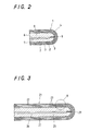
- thermocouple lance for measuring temperatures in molten metal baths according to the present invention will be explained with reference to FIGS. 3 to 6.
- thermocouple lance as apparent from FIGS. 3 to 6, comprises a protective sheath 21 of multi-layered structure with one closed and one open end wherein a filler 25 and a pair of temperature-measuring alloy wires 26, 27 are contained.
- the temperature-measuring wires 26, 27 consist of two wires of different metal alloys in composition, the wires being embedded with the filler 25 and joined together at their confronting ends to form a thermocouple junction placed where the temperature is to be measured.
- the protective sheath 21 is composed of plural cermet layers 22 each having a molybdenum matrix, the layers 22 being arranged in concentric relation with each other to form a layered structure.
- each layer 22 of the protective sheath 21 made less in the thermal conductivity.
- the filler 8 may have such structure that is rich in porosity to make the thermal conductivity less, thereby rendering the temperature-measuring zone 4 of the protective sheath 1 less in thermal capacity. This makes it possible to arrest the heat conduction backward from the temperature-measuring zone 4 immersed in the molten metal baths, so that the thermocouple lance may be improved in the rapid response of the temperature measurement.
- the protective sheath 1 of the layered structure is superior in the thermal shock as well as corrosion resistances. That is, the multi-layered structure may retard the propagation of cracks which have occurred in the outermost shell layerof heat resisting carbon filaments and ceramic filaments.
- the carbon filaments are coated with at least any one of Mg, CaO, ZrO 2 and Al 2 O 3 so as to be protected against oxidation.
- the boundary layers 23 are composed of any one of carbon and boron nitride (BN).
- the cermet layers 22 of the protective sheath 21 constitute at least the outermost shell layer exposed directly to the molten metals and therefore are comprised of any one of Mo-ZrN, Mo-ZrB 2 , Mo-ZrO 2 , Mo-ZrC and composite thereof, which is less in coefficient of thermal expansion and hard to be subjected to the reaction with molten metals.
- thermocouple wires 26, 27 are of tungsten-rhenium alloys, one 26 of which wires has the composition of W-5Re while the other 27 has the composition of W-26Re. Both the W-5Re wire 26 and W-26Re wire 27 are arranged in the protective sheath 21 in spaced relation from each other and buried in the filler 25 compacted in the protective sheath 21. The W-5Re wire 26 and W-26Re wire 27 are jointed with each other at their confronting ends to form the hot junction 29 where the temperature is to be measured.
- the opposite ends of the W-5Re wire 26 and W-26Re wire 27 extend outwardly of the sheath through the sealing plug, not shown, at the open end of the protective sheath 21 into ceramic cement filled in the sealing pipe that is mounted on the open end of the protective sheath 21.
- the wires in the ceramic cement are connected with terminals through, for example, leads or cold-junction compensation in the tubes made of kovar.
- the sealing pipe constitutes a kind of supporting ring.
- the filler 25 is porous heat resisting ceramics composed of a mixture of heat resisting ceramic powder with any one of reaction-sintered silicon nitride with the addition of Ti and inorganic substance converted from organosilicon polymer, especially polycarbosilane, containing therein Si 3 N 4 powder.
- the mixture contains therein at least one of carbon and boron nitride (BN).
- the porous heat resisting ceramics for the filler 25 are recommended to contain Zr, O, Al and P. It is to be noted that the filler 25 compacted in the protective sheath 21 is formed in the porous or cellular structure of a substance such as reaction sintered Si 3 N 4 ceramics, which is made less in the thermal conductivity.
- the protective sheath 21 of the layered structure is superior in the thermal shock as well as corrosion resistances. That is, the multi-layered structure may retard the propagation of cracks which have occurred in the outermost shell layer due to the thermal shock, so that the lethal rupture may be avoided that might otherwise occur in the protective sheath having the conventional ceramic shell.
- the protective sheath 1 is kept from the stain with the molten metal 28, to thereby help ensure the repetitive measuring services.
- the following examples serve to illustrate the preferred method of producing the thermocouple lance of the present invention.
- thermocouple lance for measuring the temperatures in the molten metals according to the second embodiment of the present invention.
- the sheets were first formed of the cermet, or Mo-ZrO 2 , Mo-ZrN, Mo-ZrB 2 and Mo-ZrC, having the molybdenum matrix.
- the carbon filaments were coated with at least any one of Mg, CaO, ZrO 2 and Al 2 O 3 so as to be kept from the oxidation. Then, the carbon filaments were arranged on the sheets while oriented in a predetermined direction.
- the sheets of Mo-ZrO 2 were laid one on top of another. We thereafter wound the piled sheets around a stainless steel-made mandrel while spraying graphite powder inside the piled sheets to thereby form a tubular member of multi-layered structure.
- the tubular member was closed at its lengthwise one end and charged in an elastic mould in which the tubular member underwent the secondary molding under the cold isostatic pressing so as to be formed in a densified, integrated tubular product.
- the product after being subjected to debinding process, was burned in hydrogen atmosphere at 1800°C, forming the protective sheath 21 of multi-layered structure with one closed end and one open end.
- FIGS. 3 to 4 show the protective sheath 21 fabricated as described above.
- the protective sheath 21 was filled with a solution of organosilicon polymer, especially, polycarbosilane, containing therein Si 3 N 4 powder, and the W-Re wires 26, 27 joined together at their one ends were inserted in the protective sheath 21 to a place where the junction comes close to the closed end of the protective sheath 21.
- the protective sheath 21 was then closed at its open end by means of the sealing plug of dense glass (B 2 O 3 -ZnO).
- the stainless holder tube, or sealing tube was secured on the plugged end of the protective sheath 21 by means of a collet chuck or the like to thereby finish the thermocouple lance.
- thermocouple lance was produced by the manufacturing method substantially identical with the method described above, except that the filler 25, prior to charged into the protective sheath 21, was added with each 5% of carbon and boron nitride (BN) to adjust its composition so as to be capable of keeping the W-Re wires 26, 27 from the oxidation. That is, it is true that the added carbon and boron nitride (BN) in the filler 25 may predominantly react with oxygen in the filler 25 while protecting the W-Re wires 26, 27 from the oxidation with the result the W-Re wires 26, 27 may be improved in durability.
- the filler 25 prior to charged into the protective sheath 21, was added with each 5% of carbon and boron nitride (BN) to adjust its composition so as to be capable of keeping the W-Re wires 26, 27 from the oxidation. That is, it is true that the added carbon and boron nitride (BN) in the filler 25 may predominantly react with oxygen in the filler 25 while protecting the W-Re wire
- thermocouple lances having the protective sheaths 21 and 31, respectively.
- thermocouple lance having the protective sheath 31 in FIG. 8 was damaged at about 300 cycles of the repetitive temperature-measuring works in the molten metals.
- thermocouple lances after repetitive exposures to the molten metals, had cracks in the protective sheath 31. Nevertheless the cracks were found to propagate in a deflected pattern 33, as shown in FIG. 8, at the boundary layers for the layered structure whereby the life expectancy of the thermocouple lances was improved in the number of cycles of the repetitive temperature-measuring works as compared with the protective sheath 41.
- thermocouple lance having the protective sheath 41 in FIG. 9 had cracks at just only about 20 cycles of the repetitive temperature-measuring services.
- the cracks propagated to the interior of the protective sheath in a straight line as shown with an arrow in FIG. 9.
- thermocouple lance with the protective sheath 21 in FIG. 4 was found to be still sufficiently durable for measuring the temperatures in the molten metals, even after about 800 cycles of the repetitive temperature-measuring services.
- thermocouple lances after repetitive exposures to the molten metals, had cracks in the protective sheath 21. Nevertheless the cracks were found to propagate in a deflected condition at carbon filaments 24 as well as the boundary layers 23 due to the multi-layered structure with the wound carbon filaments.
- the crack propagation was repressed whereby the life expectancy of the thermocouple lances was improved over both the protective sheaths 31, 41 in the number of cycles of the repetitive temperature-measuring works.
- thermocouple lance with any one of the protective sheaths 31, 42 is immersed aments were coated with at least any one of Mg, CaO, ZrO 2 and Al 2 O 3 so as to be kept from the oxidation. Then, the carbon filaments were arranged on the sheets while oriented in a predetermined direction. The sheets of Mo-ZrO 2 were laid one on top of another. We thereafter wound the piled sheets around a stainless steel-made mandrel while spraying graphite powder inside the piled sheets to thereby form a tubular member of multi-layered structure.
- the tubular member was closed at its lengthwise one end and charged in an elastic mould in which the tubular member underwent the secondary molding under the cold isostatic pressing so as to be formed in a densified, integrated tubular product.
- the product after being subjected to debinding process, was burned in hydrogen atmosphere at 1800 °C, forming the protective sheath 21 of multi-layered structure with one closed end and one open end.
- FIGS. 3 to 4 show the protective sheath 21 fabricated as described above.
- the protective sheath 21 was filled with a solut was really repressed whereby the endurance of the protective sheath 21 was improved remarkably.
Landscapes
- Physics & Mathematics (AREA)
- General Physics & Mathematics (AREA)
- Measuring Temperature Or Quantity Of Heat (AREA)
Applications Claiming Priority (4)
| Application Number | Priority Date | Filing Date | Title |
|---|---|---|---|
| JP1474598 | 1998-01-12 | ||
| JP10014745A JPH11201831A (ja) | 1998-01-12 | 1998-01-12 | 金属溶湯測温用熱電対 |
| JP2013498 | 1998-01-19 | ||
| JP02013498A JP3603582B2 (ja) | 1998-01-19 | 1998-01-19 | 金属溶湯測温用熱電対 |
Publications (2)
| Publication Number | Publication Date |
|---|---|
| EP0928958A2 true EP0928958A2 (de) | 1999-07-14 |
| EP0928958A3 EP0928958A3 (de) | 1999-09-01 |
Family
ID=26350757
Family Applications (1)
| Application Number | Title | Priority Date | Filing Date |
|---|---|---|---|
| EP99300099A Withdrawn EP0928958A3 (de) | 1998-01-12 | 1999-01-06 | Umhüllte thermoelektrische Lanze zum Messen der Temperatur in einer Metallschmelze |
Country Status (4)
| Country | Link |
|---|---|
| US (2) | US6190038B1 (de) |
| EP (1) | EP0928958A3 (de) |
| KR (1) | KR19990066851A (de) |
| CN (1) | CN1229189A (de) |
Cited By (5)
| Publication number | Priority date | Publication date | Assignee | Title |
|---|---|---|---|---|
| EP1365219A3 (de) * | 2002-05-22 | 2004-02-25 | Shin-Etsu Chemical Co., Ltd. | Schutzrohr für Thermoelement |
| WO2015021096A1 (en) * | 2013-08-07 | 2015-02-12 | Ametek, Inc. | High temperature probe |
| US9429481B2 (en) | 2012-08-31 | 2016-08-30 | Ametek, Inc. | Apparatus and method for measuring total air temperature within an airflow |
| EA037107B1 (ru) * | 2014-03-11 | 2021-02-08 | Эметек, Инк. | Высокотемпературный пробник |
| CN114956869A (zh) * | 2021-12-31 | 2022-08-30 | 昆明理工大学 | 一种镀膜层数可调的陶瓷基热电偶保护套的制备方法 |
Families Citing this family (51)
| Publication number | Priority date | Publication date | Assignee | Title |
|---|---|---|---|---|
| US6257758B1 (en) * | 1998-10-09 | 2001-07-10 | Claud S. Gordon Company | Surface temperature sensor |
| AU777791C (en) * | 1999-08-16 | 2005-05-26 | Temperature Management Systems (Proprietary) Limited | Metallurgical thermocouple |
| WO2001027579A1 (en) * | 1999-10-13 | 2001-04-19 | Texaco Development Corporation | Sapphire reinforced thermocouple protection tube |
| JP4437592B2 (ja) * | 2000-04-24 | 2010-03-24 | いすゞ自動車株式会社 | 高速応答性熱電対 |
| CN1116593C (zh) * | 2000-07-12 | 2003-07-30 | 东北大学 | 钢水温度连续测量方法和测温管 |
| US6997607B2 (en) * | 2002-11-22 | 2006-02-14 | Ngk Spark Plug Co., Ltd. | Temperature sensor |
| US20040114666A1 (en) * | 2002-12-17 | 2004-06-17 | Hardwicke Canan Uslu | Temperature sensing structure, method of making the structure, gas turbine engine and method of controlling temperature |
| CN100414277C (zh) * | 2003-11-14 | 2008-08-27 | 刘元庆 | 热电偶保护套管的制造方法 |
| US7131768B2 (en) * | 2003-12-16 | 2006-11-07 | Harco Laboratories, Inc. | Extended temperature range EMF device |
| US8004423B2 (en) * | 2004-06-21 | 2011-08-23 | Siemens Energy, Inc. | Instrumented component for use in an operating environment |
| DE102004032561B3 (de) | 2004-07-05 | 2006-02-09 | Heraeus Electro-Nite International N.V. | Behälter für Metallschmelze sowie Verwendung des Behälters |
| CN100343638C (zh) * | 2005-01-28 | 2007-10-17 | 哈尔滨工业大学 | 组装式陶瓷热电偶 |
| EP1717566A1 (de) * | 2005-04-25 | 2006-11-02 | Mettler-Toledo AG | Thermoanalytischer Sensor |
| GB2428517A (en) * | 2005-07-21 | 2007-01-31 | Weston Aerospace Ltd | Ceramic thermocouple |
| FR2892720B1 (fr) * | 2005-10-28 | 2008-05-16 | Saint Gobain Ct Recherches | Produit ceramique fritte a matrice azotee aux proprietes de surface ameliorees |
| US7368827B2 (en) * | 2006-09-06 | 2008-05-06 | Siemens Power Generation, Inc. | Electrical assembly for monitoring conditions in a combustion turbine operating environment |
| US7969323B2 (en) * | 2006-09-14 | 2011-06-28 | Siemens Energy, Inc. | Instrumented component for combustion turbine engine |
| KR100874698B1 (ko) | 2007-06-15 | 2008-12-18 | 한국표준과학연구원 | 온도 측정장치 |
| US9071888B2 (en) * | 2007-11-08 | 2015-06-30 | Siemens Aktiengesellschaft | Instrumented component for wireless telemetry |
| US8519866B2 (en) | 2007-11-08 | 2013-08-27 | Siemens Energy, Inc. | Wireless telemetry for instrumented component |
| US8797179B2 (en) * | 2007-11-08 | 2014-08-05 | Siemens Aktiengesellschaft | Instrumented component for wireless telemetry |
| DE102008005160A1 (de) * | 2008-01-18 | 2009-07-23 | Robert Bosch Gmbh | Temperatursensor |
| US7891870B2 (en) * | 2008-04-29 | 2011-02-22 | Ngk Spark Plug Co., Ltd. | Temperature sensor element and method of manufacturing the same |
| CN101783197B (zh) * | 2009-01-21 | 2013-09-04 | 中国航空工业第一集团公司沈阳发动机设计研究所 | 一种高温包覆绝缘热电偶的绝缘材料及工艺 |
| WO2010094464A2 (en) * | 2009-02-18 | 2010-08-26 | Heraeus Electro-Nite International N.V. | Temperature measuring device |
| KR101149144B1 (ko) * | 2009-07-24 | 2012-06-01 | 현대제철 주식회사 | 압연재의 온도 측정 장치 |
| US8540424B2 (en) * | 2009-12-18 | 2013-09-24 | Covidien Lp | Cover for shaft of electronic thermometer probe |
| US20120211484A1 (en) * | 2011-02-23 | 2012-08-23 | Applied Materials, Inc. | Methods and apparatus for a multi-zone pedestal heater |
| CN102156003B (zh) * | 2011-02-25 | 2013-09-25 | 武汉武钢维苏威高级陶瓷有限公司 | 热电偶总成和制造工艺 |
| KR101916238B1 (ko) | 2011-06-28 | 2019-01-30 | 엘지이노텍 주식회사 | 진공 열처리 장치 |
| IL217258A (en) * | 2011-12-28 | 2016-11-30 | Rivlin Eitan | Quick dipped thermocouple response to mixing tap |
| US9325388B2 (en) | 2012-06-21 | 2016-04-26 | Siemens Energy, Inc. | Wireless telemetry system including an induction power system |
| CN102721482A (zh) * | 2012-07-04 | 2012-10-10 | 重庆材料研究所 | 一种耐高温高压高湿度温度传感器 |
| US9103731B2 (en) | 2012-08-20 | 2015-08-11 | Unison Industries, Llc | High temperature resistive temperature detector for exhaust gas temperature measurement |
| CN103926013A (zh) * | 2013-01-15 | 2014-07-16 | 宝山钢铁股份有限公司 | 烧结用高温热电偶保护套管 |
| CN103938143B (zh) * | 2013-01-20 | 2016-01-06 | 江苏兆龙电气有限公司 | 一种用于高温铜液测温用保护套管的金属陶瓷等离子喷涂材料 |
| GB2515483A (en) | 2013-06-24 | 2014-12-31 | Weston Aerospace | Cooled Thermocouple |
| US9420356B2 (en) | 2013-08-27 | 2016-08-16 | Siemens Energy, Inc. | Wireless power-receiving assembly for a telemetry system in a high-temperature environment of a combustion turbine engine |
| CN103592049A (zh) * | 2013-10-16 | 2014-02-19 | 安徽蓝德仪表有限公司 | 一种空压机用防爆铂热电阻 |
| KR101517377B1 (ko) * | 2013-10-28 | 2015-05-06 | 한국원자력연구원 | 내구성을 가진 고온용융물 온도 측정 장치 |
| JP6421690B2 (ja) | 2014-07-17 | 2018-11-14 | 株式会社デンソー | 温度センサ |
| WO2017033035A1 (en) * | 2015-08-26 | 2017-03-02 | Brinning András Iván | Layered non oxide ceramic module as thermoelectric energy source |
| CN106404206A (zh) * | 2016-11-07 | 2017-02-15 | 宁波精丰测控技术有限公司 | 陶瓷铠装高温热电偶及其制造方法 |
| TWI648525B (zh) * | 2017-12-18 | 2019-01-21 | 國家中山科學研究院 | 一種用於量測坩堝內部熱場分布之裝置 |
| US10753807B2 (en) | 2018-01-19 | 2020-08-25 | Te Wire & Cable Llc | Thermocouple termination/closure and method |
| CN108484169A (zh) * | 2018-03-26 | 2018-09-04 | 甘肃新西北碳素科技有限公司 | 用于熔铝炉的碳/碳材料热电偶保护套制作方法 |
| CN110411599A (zh) * | 2019-08-07 | 2019-11-05 | 中国核动力研究设计院 | 可重复使用的接触式液体内部温度测量装置及测量方法 |
| PL4036539T3 (pl) * | 2021-02-01 | 2023-09-11 | Heraeus Electro-Nite International N.V. | Urządzenie zanurzeniowe do pomiaru temperatury i sposób wykrywania położenia |
| CN113851255A (zh) * | 2021-09-08 | 2021-12-28 | 常州精瓷仪器科技有限公司 | 高绝缘易流变的热电偶氮化硼基填充材料及填充方法 |
| CN115029654B (zh) * | 2021-12-31 | 2023-09-22 | 昆明理工大学 | 一种基于金属陶瓷镀层保护的合金基热电偶保护套的制备方法 |
| CN118999816A (zh) * | 2024-08-23 | 2024-11-22 | 重庆材料研究院有限公司 | 一种玻璃熔窑碹顶用高温热电偶 |
Family Cites Families (24)
| Publication number | Priority date | Publication date | Assignee | Title |
|---|---|---|---|---|
| US3647558A (en) * | 1967-06-26 | 1972-03-07 | Carborundum Co | Protected thermocouple and protection tube |
| US3607446A (en) * | 1967-11-06 | 1971-09-21 | Nuclear Materials & Equipment | Thermopile and method of making |
| US3614387A (en) * | 1969-09-22 | 1971-10-19 | Watlow Electric Mfg Co | Electrical heater with an internal thermocouple |
| GB1363006A (en) | 1971-09-21 | 1974-08-14 | Morgan Refractories Ltd | Cermet articles |
| US4060095A (en) * | 1975-08-23 | 1977-11-29 | Koransha Co., Ltd. | Thermocouple protecting tube |
| JPS5376975U (de) * | 1976-11-30 | 1978-06-27 | ||
| JPS5819524A (ja) * | 1981-07-27 | 1983-02-04 | Yamari Sangyo Kk | シ−ス型熱電対とその製造方法 |
| US4430518A (en) * | 1981-11-30 | 1984-02-07 | Denki Kagaku Kogyo Kabushiki Kaisha | Protecting tube for thermocouple |
| US4796671A (en) * | 1986-03-18 | 1989-01-10 | Hitachi Metals, Ltd. | Protective tube for thermocouple and method of producing same |
| US4749416A (en) * | 1986-08-01 | 1988-06-07 | System Planning Corporation | Immersion pyrometer with protective structure for sidewall use |
| US4721533A (en) * | 1986-08-01 | 1988-01-26 | System Planning Corporation | Protective structure for an immersion pyrometer |
| JPH0269627A (ja) * | 1988-09-06 | 1990-03-08 | Toyota Motor Corp | 熱電対用保護管 |
| US5360269A (en) * | 1989-05-10 | 1994-11-01 | Tokyo Kogyo Kabushiki Kaisha | Immersion-type temperature measuring apparatus using thermocouple |
| DE4207317C3 (de) * | 1992-03-06 | 2000-03-16 | Heraeus Electro Nite Int | Vorrichtung zur Messung der Temperatur von Metallschmelzen |
| US5296288A (en) * | 1992-04-09 | 1994-03-22 | The United States Of America As Represented By The Administrator Of The National Aeronautics And Space Administration | Protective coating for ceramic materials |
| US5209571A (en) * | 1992-07-09 | 1993-05-11 | Heraeus Electro-Nite International N.V. | Device for measuring the temperature of a molten metal |
| JPH07104214B2 (ja) | 1992-11-21 | 1995-11-13 | 助川電気工業株式会社 | 気密端子付シース型熱電対 |
| US5750958A (en) * | 1993-09-20 | 1998-05-12 | Kyocera Corporation | Ceramic glow plug |
| US5474618A (en) * | 1994-04-19 | 1995-12-12 | Rdc Controle Ltee | Protective ceramic device for immersion pyrometer |
| US5709474A (en) * | 1994-11-15 | 1998-01-20 | L&N Metallurgical Products Co. | Refractory sheath for sensors |
| US5663899A (en) * | 1995-06-05 | 1997-09-02 | Advanced Micro Devices | Redundant thermocouple |
| EP0764837A1 (de) * | 1995-09-25 | 1997-03-26 | Isuzu Ceramics Research Institute Co., Ltd. | Thermoelementstruktur |
| JPH09105677A (ja) * | 1995-10-12 | 1997-04-22 | Isuzu Ceramics Kenkyusho:Kk | セラミックシース型部品及びその製造方法 |
| JP3306427B2 (ja) * | 1997-11-21 | 2002-07-24 | いすゞ自動車株式会社 | シース構造体 |
-
1998
- 1998-12-18 KR KR1019980056015A patent/KR19990066851A/ko not_active Ceased
- 1998-12-29 US US09/222,708 patent/US6190038B1/en not_active Expired - Fee Related
-
1999
- 1999-01-06 EP EP99300099A patent/EP0928958A3/de not_active Withdrawn
- 1999-01-06 CN CN99100067A patent/CN1229189A/zh active Pending
-
2000
- 2000-12-28 US US09/750,626 patent/US6280083B2/en not_active Expired - Fee Related
Cited By (8)
| Publication number | Priority date | Publication date | Assignee | Title |
|---|---|---|---|---|
| EP1365219A3 (de) * | 2002-05-22 | 2004-02-25 | Shin-Etsu Chemical Co., Ltd. | Schutzrohr für Thermoelement |
| US9429481B2 (en) | 2012-08-31 | 2016-08-30 | Ametek, Inc. | Apparatus and method for measuring total air temperature within an airflow |
| WO2015021096A1 (en) * | 2013-08-07 | 2015-02-12 | Ametek, Inc. | High temperature probe |
| US10408683B2 (en) | 2013-08-07 | 2019-09-10 | Ametek, Inc. | High temperature probe |
| EA033593B1 (ru) * | 2013-08-07 | 2019-11-07 | Ametek Inc | Высокотемпературный пробник |
| EA037107B1 (ru) * | 2014-03-11 | 2021-02-08 | Эметек, Инк. | Высокотемпературный пробник |
| CN114956869A (zh) * | 2021-12-31 | 2022-08-30 | 昆明理工大学 | 一种镀膜层数可调的陶瓷基热电偶保护套的制备方法 |
| CN114956869B (zh) * | 2021-12-31 | 2023-09-15 | 昆明理工大学 | 一种镀膜层数可调的陶瓷基热电偶保护套的制备方法 |
Also Published As
| Publication number | Publication date |
|---|---|
| US20010002201A1 (en) | 2001-05-31 |
| KR19990066851A (ko) | 1999-08-16 |
| CN1229189A (zh) | 1999-09-22 |
| EP0928958A3 (de) | 1999-09-01 |
| US6190038B1 (en) | 2001-02-20 |
| US6280083B2 (en) | 2001-08-28 |
Similar Documents
| Publication | Publication Date | Title |
|---|---|---|
| US6190038B1 (en) | Thermocouple lance with alternating molybdenum layered sheath for measuring temperature in molten metal bath | |
| US6102565A (en) | Ceramic sheath type thermocouple | |
| US5696348A (en) | Thermocouple structure | |
| EP0887632A1 (de) | Thermoelement mit keramischer Hülle zum Messen der Temperatur von geschmolzenem Metall | |
| CA2147309C (en) | Protective ceramic device for immersion pyrometer | |
| JP4437592B2 (ja) | 高速応答性熱電対 | |
| US6040519A (en) | Unit sheath | |
| JP3603614B2 (ja) | 熱電対 | |
| JP2002013984A (ja) | 熱電対 | |
| JP3550915B2 (ja) | 高温測温用セラミック熱電対 | |
| JP3603557B2 (ja) | 金属溶湯測温用セラミック熱電対 | |
| JPH1030967A (ja) | セラミックシース型熱電対 | |
| JP2000088667A (ja) | 繊維補強型熱電対 | |
| JPH09113372A (ja) | 多点測温素子 | |
| JPH11201831A (ja) | 金属溶湯測温用熱電対 | |
| JP2613086B2 (ja) | 熱電対保護管およびその製造法 | |
| JP4484129B2 (ja) | 熱電対 | |
| JP3603582B2 (ja) | 金属溶湯測温用熱電対 | |
| JP3355166B2 (ja) | 金属溶湯測温用熱電対 | |
| JP3398105B2 (ja) | 熱電対 | |
| JP3306425B2 (ja) | 高温測温用セラミック熱電対 | |
| JP4416146B2 (ja) | 熱電対 | |
| JP3329189B2 (ja) | セラミックシース型熱電対 | |
| JP3641759B2 (ja) | 熱電対と保護管が一体となった測温センサーの製造方法 | |
| JP3533944B2 (ja) | 破壊検知機能付き熱電対用保護管の構造 |
Legal Events
| Date | Code | Title | Description |
|---|---|---|---|
| PUAI | Public reference made under article 153(3) epc to a published international application that has entered the european phase |
Free format text: ORIGINAL CODE: 0009012 |
|
| AK | Designated contracting states |
Kind code of ref document: A2 Designated state(s): DE FR GB |
|
| AX | Request for extension of the european patent |
Free format text: AL;LT;LV;MK;RO;SI |
|
| PUAL | Search report despatched |
Free format text: ORIGINAL CODE: 0009013 |
|
| RIN1 | Information on inventor provided before grant (corrected) |
Inventor name: SUZUKI, TAKAYUKI Inventor name: KITA, HIDEKI |
|
| AK | Designated contracting states |
Kind code of ref document: A3 Designated state(s): AT BE CH CY DE DK ES FI FR GB GR IE IT LI LU MC NL PT SE |
|
| AX | Request for extension of the european patent |
Free format text: AL;LT;LV;MK;RO;SI |
|
| 17P | Request for examination filed |
Effective date: 19991210 |
|
| AKX | Designation fees paid |
Free format text: DE FR GB |
|
| STAA | Information on the status of an ep patent application or granted ep patent |
Free format text: STATUS: THE APPLICATION IS DEEMED TO BE WITHDRAWN |
|
| 18D | Application deemed to be withdrawn |
Effective date: 20020801 |