EP0928897A2 - Dispositif d'articulation pour un plateau en biais - Google Patents
Dispositif d'articulation pour un plateau en biais Download PDFInfo
- Publication number
- EP0928897A2 EP0928897A2 EP99100506A EP99100506A EP0928897A2 EP 0928897 A2 EP0928897 A2 EP 0928897A2 EP 99100506 A EP99100506 A EP 99100506A EP 99100506 A EP99100506 A EP 99100506A EP 0928897 A2 EP0928897 A2 EP 0928897A2
- Authority
- EP
- European Patent Office
- Prior art keywords
- swash plate
- drive plate
- drive shaft
- hinge part
- compressor according
- Prior art date
- Legal status (The legal status is an assumption and is not a legal conclusion. Google has not performed a legal analysis and makes no representation as to the accuracy of the status listed.)
- Withdrawn
Links
- 230000007246 mechanism Effects 0.000 claims abstract description 39
- XEEYBQQBJWHFJM-UHFFFAOYSA-N Iron Chemical compound [Fe] XEEYBQQBJWHFJM-UHFFFAOYSA-N 0.000 claims abstract description 26
- 238000006073 displacement reaction Methods 0.000 claims abstract description 21
- 229910052782 aluminium Inorganic materials 0.000 claims abstract description 14
- XAGFODPZIPBFFR-UHFFFAOYSA-N aluminium Chemical compound [Al] XAGFODPZIPBFFR-UHFFFAOYSA-N 0.000 claims abstract description 14
- 229910052742 iron Inorganic materials 0.000 claims abstract description 13
- 229910000838 Al alloy Inorganic materials 0.000 claims abstract description 11
- 239000000956 alloy Substances 0.000 claims abstract description 9
- 239000007769 metal material Substances 0.000 claims abstract description 8
- 239000002245 particle Substances 0.000 claims description 9
- 229910052710 silicon Inorganic materials 0.000 claims description 4
- 239000010703 silicon Substances 0.000 claims description 4
- 230000008859 change Effects 0.000 claims description 3
- 238000003466 welding Methods 0.000 claims description 3
- 239000003507 refrigerant Substances 0.000 description 10
- 239000000463 material Substances 0.000 description 4
- 229910052751 metal Inorganic materials 0.000 description 4
- 239000002184 metal Substances 0.000 description 4
- XUIMIQQOPSSXEZ-UHFFFAOYSA-N Silicon Chemical compound [Si] XUIMIQQOPSSXEZ-UHFFFAOYSA-N 0.000 description 3
- 238000004519 manufacturing process Methods 0.000 description 3
- 238000010276 construction Methods 0.000 description 2
- 238000001816 cooling Methods 0.000 description 2
- 230000002093 peripheral effect Effects 0.000 description 2
- PMVSDNDAUGGCCE-TYYBGVCCSA-L Ferrous fumarate Chemical compound [Fe+2].[O-]C(=O)\C=C\C([O-])=O PMVSDNDAUGGCCE-TYYBGVCCSA-L 0.000 description 1
- 238000004378 air conditioning Methods 0.000 description 1
- 230000005496 eutectics Effects 0.000 description 1
- 230000005484 gravity Effects 0.000 description 1
- 230000002452 interceptive effect Effects 0.000 description 1
- 238000000034 method Methods 0.000 description 1
- 230000008569 process Effects 0.000 description 1
- 238000005493 welding type Methods 0.000 description 1
Images


Classifications
-
- F—MECHANICAL ENGINEERING; LIGHTING; HEATING; WEAPONS; BLASTING
- F04—POSITIVE - DISPLACEMENT MACHINES FOR LIQUIDS; PUMPS FOR LIQUIDS OR ELASTIC FLUIDS
- F04B—POSITIVE-DISPLACEMENT MACHINES FOR LIQUIDS; PUMPS
- F04B27/00—Multi-cylinder pumps specially adapted for elastic fluids and characterised by number or arrangement of cylinders
- F04B27/08—Multi-cylinder pumps specially adapted for elastic fluids and characterised by number or arrangement of cylinders having cylinders coaxial with, or parallel or inclined to, main shaft axis
- F04B27/10—Multi-cylinder pumps specially adapted for elastic fluids and characterised by number or arrangement of cylinders having cylinders coaxial with, or parallel or inclined to, main shaft axis having stationary cylinders
- F04B27/1036—Component parts, details, e.g. sealings, lubrication
- F04B27/1054—Actuating elements
- F04B27/1072—Pivot mechanisms
-
- F—MECHANICAL ENGINEERING; LIGHTING; HEATING; WEAPONS; BLASTING
- F04—POSITIVE - DISPLACEMENT MACHINES FOR LIQUIDS; PUMPS FOR LIQUIDS OR ELASTIC FLUIDS
- F04B—POSITIVE-DISPLACEMENT MACHINES FOR LIQUIDS; PUMPS
- F04B27/00—Multi-cylinder pumps specially adapted for elastic fluids and characterised by number or arrangement of cylinders
- F04B27/08—Multi-cylinder pumps specially adapted for elastic fluids and characterised by number or arrangement of cylinders having cylinders coaxial with, or parallel or inclined to, main shaft axis
- F04B27/10—Multi-cylinder pumps specially adapted for elastic fluids and characterised by number or arrangement of cylinders having cylinders coaxial with, or parallel or inclined to, main shaft axis having stationary cylinders
- F04B27/1036—Component parts, details, e.g. sealings, lubrication
- F04B27/1054—Actuating elements
-
- F—MECHANICAL ENGINEERING; LIGHTING; HEATING; WEAPONS; BLASTING
- F04—POSITIVE - DISPLACEMENT MACHINES FOR LIQUIDS; PUMPS FOR LIQUIDS OR ELASTIC FLUIDS
- F04B—POSITIVE-DISPLACEMENT MACHINES FOR LIQUIDS; PUMPS
- F04B27/00—Multi-cylinder pumps specially adapted for elastic fluids and characterised by number or arrangement of cylinders
- F04B27/08—Multi-cylinder pumps specially adapted for elastic fluids and characterised by number or arrangement of cylinders having cylinders coaxial with, or parallel or inclined to, main shaft axis
- F04B27/0873—Component parts, e.g. sealings; Manufacturing or assembly thereof
- F04B27/0878—Pistons
-
- F—MECHANICAL ENGINEERING; LIGHTING; HEATING; WEAPONS; BLASTING
- F04—POSITIVE - DISPLACEMENT MACHINES FOR LIQUIDS; PUMPS FOR LIQUIDS OR ELASTIC FLUIDS
- F04B—POSITIVE-DISPLACEMENT MACHINES FOR LIQUIDS; PUMPS
- F04B27/00—Multi-cylinder pumps specially adapted for elastic fluids and characterised by number or arrangement of cylinders
- F04B27/08—Multi-cylinder pumps specially adapted for elastic fluids and characterised by number or arrangement of cylinders having cylinders coaxial with, or parallel or inclined to, main shaft axis
- F04B27/10—Multi-cylinder pumps specially adapted for elastic fluids and characterised by number or arrangement of cylinders having cylinders coaxial with, or parallel or inclined to, main shaft axis having stationary cylinders
- F04B27/1036—Component parts, details, e.g. sealings, lubrication
- F04B27/1045—Cylinders
-
- F—MECHANICAL ENGINEERING; LIGHTING; HEATING; WEAPONS; BLASTING
- F05—INDEXING SCHEMES RELATING TO ENGINES OR PUMPS IN VARIOUS SUBCLASSES OF CLASSES F01-F04
- F05B—INDEXING SCHEME RELATING TO WIND, SPRING, WEIGHT, INERTIA OR LIKE MOTORS, TO MACHINES OR ENGINES FOR LIQUIDS COVERED BY SUBCLASSES F03B, F03D AND F03G
- F05B2210/00—Working fluid
- F05B2210/10—Kind or type
- F05B2210/14—Refrigerants with particular properties, e.g. HFC-134a
-
- F—MECHANICAL ENGINEERING; LIGHTING; HEATING; WEAPONS; BLASTING
- F05—INDEXING SCHEMES RELATING TO ENGINES OR PUMPS IN VARIOUS SUBCLASSES OF CLASSES F01-F04
- F05C—INDEXING SCHEME RELATING TO MATERIALS, MATERIAL PROPERTIES OR MATERIAL CHARACTERISTICS FOR MACHINES, ENGINES OR PUMPS OTHER THAN NON-POSITIVE-DISPLACEMENT MACHINES OR ENGINES
- F05C2201/00—Metals
- F05C2201/02—Light metals
- F05C2201/021—Aluminium
-
- F—MECHANICAL ENGINEERING; LIGHTING; HEATING; WEAPONS; BLASTING
- F05—INDEXING SCHEMES RELATING TO ENGINES OR PUMPS IN VARIOUS SUBCLASSES OF CLASSES F01-F04
- F05C—INDEXING SCHEME RELATING TO MATERIALS, MATERIAL PROPERTIES OR MATERIAL CHARACTERISTICS FOR MACHINES, ENGINES OR PUMPS OTHER THAN NON-POSITIVE-DISPLACEMENT MACHINES OR ENGINES
- F05C2203/00—Non-metallic inorganic materials
- F05C2203/06—Silicon
-
- F—MECHANICAL ENGINEERING; LIGHTING; HEATING; WEAPONS; BLASTING
- F05—INDEXING SCHEMES RELATING TO ENGINES OR PUMPS IN VARIOUS SUBCLASSES OF CLASSES F01-F04
- F05C—INDEXING SCHEME RELATING TO MATERIALS, MATERIAL PROPERTIES OR MATERIAL CHARACTERISTICS FOR MACHINES, ENGINES OR PUMPS OTHER THAN NON-POSITIVE-DISPLACEMENT MACHINES OR ENGINES
- F05C2251/00—Material properties
- F05C2251/10—Hardness
-
- Y—GENERAL TAGGING OF NEW TECHNOLOGICAL DEVELOPMENTS; GENERAL TAGGING OF CROSS-SECTIONAL TECHNOLOGIES SPANNING OVER SEVERAL SECTIONS OF THE IPC; TECHNICAL SUBJECTS COVERED BY FORMER USPC CROSS-REFERENCE ART COLLECTIONS [XRACs] AND DIGESTS
- Y10—TECHNICAL SUBJECTS COVERED BY FORMER USPC
- Y10S—TECHNICAL SUBJECTS COVERED BY FORMER USPC CROSS-REFERENCE ART COLLECTIONS [XRACs] AND DIGESTS
- Y10S417/00—Pumps
Definitions
- the present invention relates to variable displacement compressors that are used, for example, in vehicle air conditioners.
- variable displacement compressors examples are disclosed in Japanese unexamined patent publication No. 8-311634 and No. 9-60587.
- a housing of the respective variable displacement compressor defines cylinder bores, each of which receives a piston.
- the housing rotatably supports a drive shaft, and a rotor is fixed to the drive shaft.
- a pivotal swash plate which is connected to the piston, engages and is guided by the drive shaft.
- the swash plate is often made of aluminum or aluminum alloy material to reduce the weight of the compressor.
- a hinge mechanism connects the rotor to the swash plate. The swash plate is rotated integrally with the drive shaft through the rotor and the hinge mechanism. The hinge mechanism permits pivotal motion and sliding motion of the swash plate.
- the hinge mechanism includes a first hinge part, which extends from the swash plate, and a second hinge part, which extends from the rotor.
- the hinge mechanism further includes a pair of guide pins. A base end of each guide pin is press fitted into a corresponding mounting hole of the first hinge part. A distal end of each guide pin is slidably received in a corresponding guide hole of the second hinge part. When the swash plate is moved in an axial direction of the drive shaft, the distal end of each guide pin slides in the corresponding guide hole to guide the motion of the swash plate.
- Rotation of the drive shaft is converted to reciprocation of each piston through the rotor, the hinge mechanism and the swash plate.
- the refrigerant gas is drawn into the cylinder bore.
- the refrigerant gas is compressed in the cylinder bore and, then, is discharged from the cylinder bore.
- the displacement of the variable displacement compressor can be adjusted by changing the inclination of the swash plate to change the stroke of the piston.
- the first hinge part is integrally formed with the swash plate. That is, the first hinge part is also made of aluminum or aluminum alloy material. Therefore, in comparison to first hinge parts that are integrally formed with an iron-based swash plate, an aluminum-based first hinge part is less rigid. As a result, it is difficult to form an aluminum-based first hinge part that has satisfactory strength. Furthermore, it is difficult to press fit the base end of the guide pin into the mounting hole of an aluminum-based first hinge part in a manner that assures satisfactory strength.
- the present invention addresses the above disadvantages. It is an objective of the present invention to provide a variable displacement compressor that has a light weight drive plate and a strong hinge mechanism.
- variable displacement compressor of this invention has a housing, wherein a cylinder bore is formed in the housing, a piston located in the cylinder bore, a drive shaft rotatably supported by the housing, a rotor mounted on the drive shaft to rotate integrally with the drive shaft, a drive plate, and a hinge mechanism.
- the drive plate is connected to the piston to convert rotation of the drive shaft to reciprocation of the piston.
- the drive plate inclines and slides axially along the drive shaft, which varies the piston stroke to change the displacement of the compressor.
- the hinge mechanism is located between the rotor and the drive plate for rotating the drive plate integrally with the rotor and for guiding the motion of the drive plate.
- the hinge mechanism includes a first hinge part, which is connected to the drive plate, and a second hinge part, which extends from the rotor.
- the first and second hinge parts are coupled to one another to permit both pivoting and sliding motion between the first and second hinge parts.
- the drive plate is made of aluminum or aluminum alloy material.
- the first hinge part is separate from the drive plate and is made of iron-based metal material.
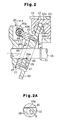
- a variable displacement compressor having single-headed pistons according to a first embodiment of the present invention for use in a vehicle air conditioning system will be described with reference to Figs. 1 to 4.
- a front housing 11 is coupled to the front end of a cylinder block 12, which serves as a center housing.
- a rear housing 13 is coupled to the rear end of the cylinder block 12, and a valve plate 14 is placed between the cylinder block 12 and the rear housing 13.
- a crank chamber 15 is defined between the front housing 11 and the cylinder block 12.
- a drive shaft 16 extends through the crank chamber 15. The ends of the drive shaft 16 are rotatably supported by the front housing 11 and the cylinder block 12, respectively.
- the drive shaft 16 is coupled to an external drive source (not shown), or a vehicle engine, by a clutch mechanism such as an electromagnetic clutch. Therefore, by engaging the electromagnetic clutch while the vehicle engine is running, the drive shaft 16 is driven to rotate.
- a rotor 17, which functions as a rotary support, is fixed to the drive shaft 16 in the crank chamber 15.
- a swash plate 18, which functions as a drive plate is pivotally supported by a hinge mechanism 20 and can slide along the drive shaft 16.
- the drive shaft 16 extends through a central through-hole 19 in the swash plate 18.
- the hinge mechanism 20 is provided between the rotor 17 and the swash plate 18 to rotate the swash plate 18 integrally with the drive shaft 16 and the rotor 17.
- the hinge mechanism 20 allows the swash plate 18 to incline and slide in the axial direction L of the drive shaft 16.
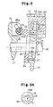
- FIG. 2 A circular hole is first drilled in the center of the swash plate 18. Then, a rotating end mill having substantially the same diameter as that of the circular hole is inserted through the circular hole. While the end mill occupies the circular hole, the end mill is pivoted for a predetermined angle about an axis S.
- the axis S is located opposite to the hinge mechanism 20 with respect to the axis L of the drive shaft 16 and extends in a direction perpendicular to the center axis of the swash plate 18.
- an engaging section 19a which forms an arcuate surface about the axis S, is formed at the inner surface of the through-hole 19 on the side that is opposite to the hinge mechanism 20 with respect to the axis L of the drive shaft 16.
- the engaging section 19a always engages the drive shaft 16 during rotation of the swash plate 18.
- a swing arm 43 which functions as a first hinge part, extends from the front face of the swash plate 18 toward the rotor 17.
- the swash plate 18 has a top dead center positioning section 18a for positioning a corresponding piston at its top dead center position.
- the longitudinal axis of the swing arm 43 lies in a plane D (Fig. 4), which extends from a center of the top dead center positioning section 18a of the swash plate 18 and includes the axis L of the drive shaft 16.
- a mounting hole 43a extends through the distal end of the swing arm 43 in a direction perpendicular to the plane D.
- a guide pin 44 which is made of iron-based metal, is press fitted into the mounting hole 43a. The ends 44a of the guide pin 44 respectively extend outwardly from the sides of the swing arm 43.
- a pair of support arms 45 extends from the rear face of the rotor 17 toward the swash plate 18.
- the support arms 45 are symmetrically arranged with respect to the plane D and function as a second hinge part.
- the swing arm 43 is held between the support arms 45.
- each support arm 45 has an oblong guide hole 45a that extends obliquely toward the drive shaft 16.
- the ends 44a (Fig. 4) of the guide pin 44 are received in the corresponding guide holes 45a of the support arms 45.
- a counter-weight 21 is attached to the front face of the swash plate 18 on a side that is opposite to the swing arm 43 with respect to the axis L of the drive shaft 16.
- cylinder bores 12a (only one of the cylinder bores 12a is shown in Fig. 1) are formed in the cylinder block 12 to extend parallel to the axis L of the drive shaft 16.
- the cylinder bores 12a are arranged at equal angular intervals about the axis L of the drive shaft 16.
- a single-headed piston 23 is received in each cylinder bore 12a.
- Each piston 23 engages a peripheral region of the swash plate 18 via a pair of semispherical shoes 24.
- a suction chamber 25 is centrally defined in the rear housing 13.
- a discharge chamber 26 is defined adjacent to the outer circumference of the rear housing 13.
- a suction port 27, a suction valve flap 28, a discharge port 29 and a discharge valve flap 30 are formed in the valve plate 14 for each cylinder bore 12a.
- the swash plate 18 rotates integrally with the drive shaft 16 through the rotor 17 and the hinge mechanism 20.
- the rotation of the swash plate 18 is converted to reciprocation of each piston 23 in its cylinder bore 12a through the shoes 24.
- Fig. 1 shows one of the pistons 23 at its top dead center position.
- the piston 23 shown in Fig. 1 will be positioned at its bottom dead center position.
- the refrigerant gas in the suction chamber 25 is drawn through the suction port 27 and the suction valve flap 28 into the cylinder bore 12a.
- the refrigerant gas in the cylinder bore 12a is compressed and is discharged through the discharge port 29 and the discharge valve flap 30 into the discharge chamber 26.
- a gas relieving passage 35 is defined in the center of the valve plate 14 for connecting the crank chamber 15 with the suction chamber 25.
- the rear end of the drive shaft 16 is supported by a bearing in a support hole 12b that is formed in the center of the cylinder block 12.
- the refrigerant gas in the crank chamber 15 flows through gaps in the bearing and through the gas relieving passage 35 into the suction chamber 25.
- a supply passage 36 extends through the rear housing 13, the valve plate 14 and the cylinder block 12 to connect the discharge chamber 26 with the crank chamber 15.
- a displacement control valve 37 is provided in the supply passage 36 within the rear housing 13.
- a pressure introduction passage 38 is formed in the rear housing 13 to introduce the pressure (suction pressure) of the suction chamber 25 to the displacement control valve 37.
- the displacement control valve 37 includes a valve body 37b, which regulates the size of the opening area of the supply passage 36, and a diaphragm 37a, which moves the valve body 37b in accordance with the suction pressure, which is applied to the diaphragm 37a through the pressure introduction passage 38.
- the suction pressure is increased. This will exert a higher pressure on the diaphragm 37a to reduce the opening area of the supply passage 36 with the valve body 37b. As a result, the amount of refrigerant gas that is supplied from the discharge chamber 26 to the crank chamber 15 through the supply passage 36 is accordingly reduced. Since more refrigerant gas is leaving the crank chamber 15 through the gas relieving passage 35 than is entering through the supply passage 36, the pressure of the refrigerant gas in the crank chamber 15 falls. As a result, the inclination of the swash plate 18 is increased. Therefore, the stroke of the pistons 23 is increased to increase the displacement of the compressor, and the suction pressure is reduced accordingly.
- the suction pressure in the suction chamber 25 is reduced. This will reduce the pressure on the upper side of the diaphragm 37a, which increases the opening area of the supply passage 36 with the valve body 37b. As a result, the amount of the refrigerant gas that is supplied from the discharge chamber 26 to the crank chamber 15 through the supply passage 36 is increased, causing the pressure of the crank chamber 15 to increase. As a result, the inclination of the swash plate 18 is reduced. Therefore, the stroke of the pistons 23 is reduced to reduce the displacement of the compressor, so the suction pressure is accordingly increased.
- the swash plate 18 is made of aluminum or aluminum alloy material.
- the aluminum alloy material of the present invention includes hard particles that are made of eutectic silicon or hyper-eutectic silicon.
- a hard particle content is preferably more than 12 wt% (weight percentage) of the aluminum alloy material. If the hard particle content is less than 12 wt%, satisfactory wear resistance cannot be achieved at the engaging surfaces of the swash plate 18, such as the peripheral surface that engages the shoes 24, and the engaging section 19a that engages the drive shaft 16.
- the average diameter of the hard particles is preferably in a range of 10 to 60 ⁇ m, more preferably in a range of 30 to 40 ⁇ m and most preferably in a range of 34 to 37 ⁇ m. If the average diameter of the hard particles is less than 10 ⁇ m or greater than 60 ⁇ m, the satisfactory wear resistance cannot be achieved at the engaging surfaces of the swash plate 18.
- the swing arm 43 is separate from the swash plate 18 and is made of the iron-based metal material.
- the swing arm 43 and the counter-weight 21 are integrally formed on a base ring 46.
- the base ring 46 is fixed to the front face of the swash plate 18 by bolts 47 around the drive shaft 16.
- the shape of the base ring 46 is suitable for integrating the swing arm 43 and the counter-weight 21 and for attaching the swing arm 43 and the counter-weight 21 to the swash plate 18 without interfering with the rotation of the drive shaft 16.
- the counter-weight 21 is provided to maintain the rotational balance of the swash plate.
- the mass and the position of the counter-weight 21 are selected to move the center of gravity of the swash plate toward the swing arm 43. Therefore, during rotation of the swash plate 18, the centrifugal force that is exerted on the swash plate 18 assures engagement between the engaging section 19a of the through-hole 19 and the drive shaft 16.
- the present embodiment provides the following advantages.
- the swash plate 18 is made of aluminum-based material that is lighter than iron-based metal material, so the weight of the compressor is reduced.
- the swing arm 43 is separate from the swash plate 18 and is made of iron-based metal material, which has more strength than aluminum-based material. Therefore, the strength and durability of the swing arm 43, which is subjected to large stresses, are improved.
- the iron-based metal swing arm 43 is stronger and more rigid than swing arms that are made of aluminum-based material. Therefore, the guide pin 44 can be press fitted into the mounting hole 43a of the swing arm 43 while assuring satisfactory strength in the connection between the guide pin 44 and the swing arm 43.
- the swash plate 18 is directly supported by the drive shaft 16. Therefore, the construction of the present invention is simpler than constructions using a sleeve that is slidably supported on the drive shaft and pivotally connected to the swash plate.
- the swash plate 18 is made of aluminum alloy that includes silicon hard particles, so the swash plate 18 resists wear. Therefore, even though the swash plate 18 is directly supported by the drive shaft 16, problems that are associated with wear of the swash plate 18 are prevented.
- the swing arm 43 is attached to the swash plate 18 by the bolt 47. Therefore, the attachment of the swing arm 43 to the swash plate 18 is relatively simple.
- the swing arm 43 is arranged between the support arms 45. Therefore, whether the drive shaft 16 is constructed to rotate clockwise or counterclockwise, the rotational torque of the rotor 17 is always transmitted to the swing arm 43 by the support arm 45 that is located on a trailing side of the swing arm 43. Therefore, the compressor according to the present embodiment can rotate clockwise and/or counterclockwise. As a result, one type of compressor can rotate clockwise or counterclockwise, which is more efficient than manufacturing two types of compressors, i.e., compressors that can only rotate clockwise and compressors that can only rotate counterclockwise, to meet customer's needs. This reduces the compressor manufacturing cost.
- the swing arm 43 and the counter-weight 21 are integrally formed with the base ring 46. Therefore, the number of the parts is reduced, and the manufacturing process is simplified.
- the counter-weight 21 defines the maximum inclination of the swash plate 18 by engaging the rotor 17.
- the iron-based metal counter-weight 21 has superior strength and wear resistance in comparison to an aluminum alloy counter-weight. As a result, deformation and wear of the counter-weight 21 due to engagement with the rotor 17 is impeded, so the swash plate 18 is correctly positioned at a predetermined maximum inclination.
- the present invention is not limited to the illustrated embodiment.
- the illustrated embodiment can be modified as follows.
- a second embodiment of the present invention includes a hinge mechanism 20 that is employed in compressors that rotate in only one direction (indicated with an arrow 50).
- the hinge mechanism 20 includes only one support arm 45.
- the support arm 45 is arranged on a trailing side of the swing arm 43.
- the guide pin can be fixed to the support arm 45, and the guide hole for receiving the guide pin can be formed in the swing arm 43.
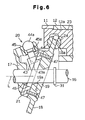
- a hinge mechanism 20 of a third embodiment is different from the hinge mechanism 20 of the first embodiment (Fig. 1).
- the same numerals are used to identify parts corresponding to those of Fig. 1.
- the support member 43 which functions as the first hinge part, is integrally formed with the counter-weight 21 on the support ring 46.
- the support member 43 and the counter-weight 21 are fixed to the swash plate 18 with the bolts 47.
- the support member 43 is made of the same material as that of the swing arm 43 of the hinge mechanism 20 of Fig. 1. That is, the support member 43 is made of iron-based metal material.
- One iron-based metal guide pin 44 is press fitted into a mounting hole 43a, which is formed in the support member 43.
- the distal end 44a of the guide pin 44 is spherical.
- the support arm 45 extends from the rear face of the rotor 17 toward the swash plate 18.
- the support arm 45 includes a guide hole 45a for receiving the spherical distal end 44a of the guide pin 44.
- the hinge mechanism 20 of Fig. 6 provides the same advantages as the hinge mechanism 20 of Fig. 1. There may be two guide pins 44 and two corresponding guide holes 45a in the support arm 45.
- the base ring 46 can be fixed to the swash plate 18 by friction welding. In so doing, the base ring 46 can be fixed to the swash plate 18 without requiring any fasteners, so the number of parts is reduced. In friction welding, the base ring 46 and the swash plate 18 are brought together under load. Then, the base ring 46 is rotated with respect to the swash plate 18. This rotation causes frictional heat to weld the base ring 46 and the swash plate 18 together.
- the base ring 46 can also be fixed to the swash plate 18 by other types of welding.
- a variable displacement compressor includes a rotor (17), which is fixed to a drive shaft (16), and a pivotal swash plate (18), which is supported on the drive shaft (16) and slides in an axial direction along the drive shaft (16).
- a hinge mechanism (20) is located between the rotor (17) and the swash plate (18). The hinge mechanism (20) rotates the swash plate (18) integrally with the rotor (17) and guides the pivoting and the sliding motion of the swash plate (18).
- the hinge mechanism (20) includes a swing arm (43), which extends from the swash plate (18).
- the swash plate (18) is made of aluminum or aluminum alloy material.
- the swing arm (43) is separate from the swash plate (18) and is made of iron-based metal material. Therefore, while the swash plate (18) is light, the hinge mechanism (20) is strong.
Landscapes
- Engineering & Computer Science (AREA)
- Mechanical Engineering (AREA)
- General Engineering & Computer Science (AREA)
- Manufacturing & Machinery (AREA)
- Compressors, Vaccum Pumps And Other Relevant Systems (AREA)
Applications Claiming Priority (2)
| Application Number | Priority Date | Filing Date | Title |
|---|---|---|---|
| JP10004768A JPH11201032A (ja) | 1998-01-13 | 1998-01-13 | 可変容量型圧縮機 |
| JP476898 | 1998-01-13 |
Publications (2)
| Publication Number | Publication Date |
|---|---|
| EP0928897A2 true EP0928897A2 (fr) | 1999-07-14 |
| EP0928897A3 EP0928897A3 (fr) | 2004-01-21 |
Family
ID=11593048
Family Applications (1)
| Application Number | Title | Priority Date | Filing Date |
|---|---|---|---|
| EP99100506A Withdrawn EP0928897A3 (fr) | 1998-01-13 | 1999-01-12 | Dispositif d'articulation pour un plateau en biais |
Country Status (5)
| Country | Link |
|---|---|
| US (1) | US6186048B1 (fr) |
| EP (1) | EP0928897A3 (fr) |
| JP (1) | JPH11201032A (fr) |
| KR (1) | KR100279223B1 (fr) |
| CN (1) | CN1225980A (fr) |
Cited By (2)
| Publication number | Priority date | Publication date | Assignee | Title |
|---|---|---|---|---|
| FR2823261A1 (fr) * | 2001-04-06 | 2002-10-11 | Sanden Corp | Compresseur a pistons axiaux a cylindree variable |
| EP1167760A3 (fr) * | 2000-06-19 | 2004-03-24 | Kabushiki Kaisha Toyota Jidoshokki | Compresseur à plateau en biais |
Families Citing this family (21)
| Publication number | Priority date | Publication date | Assignee | Title |
|---|---|---|---|---|
| KR20000060900A (ko) * | 1999-03-20 | 2000-10-16 | 신영주 | 가변용량형 사판식 압축기의 사판 최대경사각 지지구조 |
| JP4035922B2 (ja) * | 1999-04-02 | 2008-01-23 | 株式会社豊田自動織機 | 容量可変型圧縮機 |
| JP2001304102A (ja) * | 2000-04-18 | 2001-10-31 | Toyota Industries Corp | 可変容量圧縮機 |
| KR100352877B1 (ko) * | 2000-06-12 | 2002-09-16 | 한라공조주식회사 | 압축기 사판의 최대경사각 지지구조 |
| KR100661358B1 (ko) * | 2000-11-20 | 2006-12-27 | 한라공조주식회사 | 용량 가변형 사판식 압축기의 사판 힌지구조 |
| KR20020067964A (ko) * | 2001-02-19 | 2002-08-24 | 가부시키가이샤 도요다 지도숏키 | 압축기용 밸브 플레이트의 제조방법 |
| KR100441982B1 (ko) * | 2001-09-07 | 2004-07-30 | 한국과학기술연구원 | 고농도 오존 발생장치 |
| US6705841B2 (en) * | 2002-03-01 | 2004-03-16 | Visteon Global Technologies, Inc. | Variable displacement compressor with stepped shaft |
| JP2004068757A (ja) * | 2002-08-08 | 2004-03-04 | Toyota Industries Corp | 容量可変型圧縮機 |
| JP4103806B2 (ja) * | 2003-11-14 | 2008-06-18 | 株式会社豊田自動織機 | 可変容量圧縮機 |
| JP4062265B2 (ja) * | 2004-02-24 | 2008-03-19 | 株式会社豊田自動織機 | 可変容量圧縮機 |
| JP2006242120A (ja) * | 2005-03-04 | 2006-09-14 | Toyota Industries Corp | 容量可変型斜板式圧縮機 |
| US20060285981A1 (en) * | 2005-06-21 | 2006-12-21 | Visteon Global Technologies, Inc. | Swash ring compressor with spherical bearing |
| US7455009B2 (en) * | 2006-06-09 | 2008-11-25 | Visteon Global Technologies, Inc. | Hinge for a variable displacement compressor |
| JP5391648B2 (ja) * | 2008-10-28 | 2014-01-15 | 株式会社豊田自動織機 | 可変容量型圧縮機における容量制御機構 |
| JP6030822B2 (ja) * | 2010-09-28 | 2016-11-24 | Ntn株式会社 | 斜板式コンプレッサの斜板および斜板式コンプレッサ |
| DE102011076251A1 (de) * | 2011-05-23 | 2012-11-29 | Robert Bosch Gmbh | Kompressor mit Taumelscheibe |
| JP6171875B2 (ja) * | 2013-11-13 | 2017-08-02 | 株式会社豊田自動織機 | 可変容量型斜板式圧縮機 |
| US10247178B2 (en) * | 2016-03-28 | 2019-04-02 | Robert Bosch Gmbh | Variable displacement axial piston pump with fluid controlled swash plate |
| EP3885341A4 (fr) | 2018-12-29 | 2022-08-10 | Viwit Pharmaceutical Co., Ltd. | Procédé de préparation d'éfinaconazole |
| DE102019112237A1 (de) * | 2019-04-12 | 2020-10-15 | OET GmbH | Hubkolbenkompressor |
Citations (2)
| Publication number | Priority date | Publication date | Assignee | Title |
|---|---|---|---|---|
| JPH08311634A (ja) | 1995-05-17 | 1996-11-26 | Taiho Kogyo Co Ltd | 斜板式コンプレッサーの斜板及び斜板とシューとの組合わせ |
| JPH0960587A (ja) | 1995-08-21 | 1997-03-04 | Toyota Autom Loom Works Ltd | 片頭ピストン型圧縮機 |
Family Cites Families (5)
| Publication number | Priority date | Publication date | Assignee | Title |
|---|---|---|---|---|
| JPS60175783A (ja) * | 1984-02-21 | 1985-09-09 | Sanden Corp | 容量可変型斜板式圧縮機 |
| JPS61291941A (ja) * | 1985-06-19 | 1986-12-22 | Taiho Kogyo Co Ltd | Si含有量が高いAl鋳造合金 |
| JP2979687B2 (ja) * | 1991-03-26 | 1999-11-15 | 株式会社豊田自動織機製作所 | 容量可変型斜板式圧縮機 |
| JP3422186B2 (ja) * | 1995-11-24 | 2003-06-30 | 株式会社豊田自動織機 | 可変容量圧縮機 |
| JPH1193833A (ja) * | 1997-09-17 | 1999-04-06 | Toyota Autom Loom Works Ltd | 可変容量型斜板式圧縮機 |
-
1998
- 1998-01-13 JP JP10004768A patent/JPH11201032A/ja active Pending
- 1998-12-10 KR KR1019980054061A patent/KR100279223B1/ko not_active IP Right Cessation
-
1999
- 1999-01-04 US US09/226,037 patent/US6186048B1/en not_active Expired - Fee Related
- 1999-01-12 CN CN99101068A patent/CN1225980A/zh active Pending
- 1999-01-12 EP EP99100506A patent/EP0928897A3/fr not_active Withdrawn
Patent Citations (2)
| Publication number | Priority date | Publication date | Assignee | Title |
|---|---|---|---|---|
| JPH08311634A (ja) | 1995-05-17 | 1996-11-26 | Taiho Kogyo Co Ltd | 斜板式コンプレッサーの斜板及び斜板とシューとの組合わせ |
| JPH0960587A (ja) | 1995-08-21 | 1997-03-04 | Toyota Autom Loom Works Ltd | 片頭ピストン型圧縮機 |
Cited By (2)
| Publication number | Priority date | Publication date | Assignee | Title |
|---|---|---|---|---|
| EP1167760A3 (fr) * | 2000-06-19 | 2004-03-24 | Kabushiki Kaisha Toyota Jidoshokki | Compresseur à plateau en biais |
| FR2823261A1 (fr) * | 2001-04-06 | 2002-10-11 | Sanden Corp | Compresseur a pistons axiaux a cylindree variable |
Also Published As
| Publication number | Publication date |
|---|---|
| KR100279223B1 (ko) | 2001-01-15 |
| KR19990066838A (ko) | 1999-08-16 |
| JPH11201032A (ja) | 1999-07-27 |
| US6186048B1 (en) | 2001-02-13 |
| EP0928897A3 (fr) | 2004-01-21 |
| CN1225980A (zh) | 1999-08-18 |
Similar Documents
| Publication | Publication Date | Title |
|---|---|---|
| US6186048B1 (en) | Variable displacement compressor | |
| US6139282A (en) | Variable capacity refrigerant compressor with an aluminum cam plate means | |
| US5941161A (en) | Piston type compressor | |
| EP0844390B1 (fr) | Compresseur à plateau en biais comportant un plateau en matériel très résistant à l'usure | |
| US6024009A (en) | Reciprocating pistons of piston-type compressor | |
| US5984643A (en) | Variable capacity swash-plate-type refrigerant compressor | |
| EP1126165A1 (fr) | Compresseur du type a plateau oscillant a cylindree variable | |
| US20040055456A1 (en) | Variable displacement compressor | |
| EP1167760B1 (fr) | Compresseur à plateau en biais | |
| EP1148239A2 (fr) | Mécanisme à charnière pour un compresseur à capacité variable | |
| KR100282043B1 (ko) | 가변용량 사판식 압축기 | |
| US6212995B1 (en) | Variable-displacement inclined plate compressor | |
| JP3084377B2 (ja) | 圧縮機及びそれに使用するための片頭ピストン | |
| US5882179A (en) | Compressor with bearing between the drive shaft and the swash-plate boss | |
| EP0926339A2 (fr) | Revêtement d'un joint pivotable d'un plateau en biais | |
| US5771775A (en) | Device for guiding a piston | |
| EP1270942B1 (fr) | Palier de poussée pour le plateau en biais d'un compresseur | |
| US20020141883A1 (en) | Reciprocating compressors | |
| US6378417B1 (en) | Swash plate compressor in which an opening edge of each cylinder bore has a plurality of chamferred portions | |
| JP4314405B2 (ja) | 可変容量型斜板式圧縮機 | |
| EP1092873A2 (fr) | Alésages dans le cylindre d'un compresseur à plateau en biais | |
| JPH0121355B2 (fr) | ||
| EP1211416B1 (fr) | Compresseur du type a plateau oscillant | |
| US6386090B2 (en) | Piston type compressor | |
| EP1188923A2 (fr) | Revêtement d'un plateau-came d'un compresseur |
Legal Events
| Date | Code | Title | Description |
|---|---|---|---|
| PUAI | Public reference made under article 153(3) epc to a published international application that has entered the european phase |
Free format text: ORIGINAL CODE: 0009012 |
|
| 17P | Request for examination filed |
Effective date: 19990112 |
|
| AK | Designated contracting states |
Kind code of ref document: A2 Designated state(s): AT BE CH CY DE DK ES FI FR GB GR IE IT LI LU MC NL PT SE |
|
| AX | Request for extension of the european patent |
Free format text: AL;LT;LV;MK;RO;SI |
|
| RAP1 | Party data changed (applicant data changed or rights of an application transferred) |
Owner name: KABUSHIKI KAISHA TOYOTA JIDOSHOKKI |
|
| PUAL | Search report despatched |
Free format text: ORIGINAL CODE: 0009013 |
|
| AK | Designated contracting states |
Kind code of ref document: A3 Designated state(s): AT BE CH CY DE DK ES FI FR GB GR IE IT LI LU MC NL PT SE |
|
| AX | Request for extension of the european patent |
Extension state: AL LT LV MK RO SI |
|
| 17Q | First examination report despatched |
Effective date: 20040323 |
|
| AKX | Designation fees paid |
Designated state(s): DE FR IT |
|
| STAA | Information on the status of an ep patent application or granted ep patent |
Free format text: STATUS: THE APPLICATION IS DEEMED TO BE WITHDRAWN |
|
| 18D | Application deemed to be withdrawn |
Effective date: 20040802 |