EP0926489A2 - Gassensor - Google Patents
Gassensor Download PDFInfo
- Publication number
- EP0926489A2 EP0926489A2 EP98310731A EP98310731A EP0926489A2 EP 0926489 A2 EP0926489 A2 EP 0926489A2 EP 98310731 A EP98310731 A EP 98310731A EP 98310731 A EP98310731 A EP 98310731A EP 0926489 A2 EP0926489 A2 EP 0926489A2
- Authority
- EP
- European Patent Office
- Prior art keywords
- sealing
- material layer
- sensor
- metallic shell
- sensor element
- Prior art date
- Legal status (The legal status is an assumption and is not a legal conclusion. Google has not performed a legal analysis and makes no representation as to the accuracy of the status listed.)
- Granted
Links
- 239000003566 sealing material Substances 0.000 claims abstract description 48
- 239000011521 glass Substances 0.000 claims abstract description 31
- 239000002245 particle Substances 0.000 claims description 27
- 239000000945 filler Substances 0.000 claims description 12
- 239000011230 binding agent Substances 0.000 claims description 8
- 238000005259 measurement Methods 0.000 claims description 3
- 239000000203 mixture Substances 0.000 claims description 3
- 239000011148 porous material Substances 0.000 claims description 2
- 230000035939 shock Effects 0.000 abstract description 16
- 239000000126 substance Substances 0.000 abstract description 5
- 239000000454 talc Substances 0.000 abstract description 5
- 229910052623 talc Inorganic materials 0.000 abstract description 5
- 230000008602 contraction Effects 0.000 abstract 1
- 230000008646 thermal stress Effects 0.000 abstract 1
- 239000000919 ceramic Substances 0.000 description 32
- 239000000843 powder Substances 0.000 description 23
- QVGXLLKOCUKJST-UHFFFAOYSA-N atomic oxygen Chemical compound [O] QVGXLLKOCUKJST-UHFFFAOYSA-N 0.000 description 19
- 239000001301 oxygen Substances 0.000 description 19
- 229910052760 oxygen Inorganic materials 0.000 description 19
- 239000007789 gas Substances 0.000 description 16
- VYPSYNLAJGMNEJ-UHFFFAOYSA-N Silicium dioxide Chemical compound O=[Si]=O VYPSYNLAJGMNEJ-UHFFFAOYSA-N 0.000 description 10
- 239000004927 clay Substances 0.000 description 10
- PNEYBMLMFCGWSK-UHFFFAOYSA-N aluminium oxide Inorganic materials [O-2].[O-2].[O-2].[Al+3].[Al+3] PNEYBMLMFCGWSK-UHFFFAOYSA-N 0.000 description 8
- 229910052593 corundum Inorganic materials 0.000 description 8
- 238000007789 sealing Methods 0.000 description 8
- 229910001845 yogo sapphire Inorganic materials 0.000 description 8
- 239000000463 material Substances 0.000 description 6
- 238000003466 welding Methods 0.000 description 6
- 239000000377 silicon dioxide Substances 0.000 description 5
- MCMNRKCIXSYSNV-UHFFFAOYSA-N Zirconium dioxide Chemical compound O=[Zr]=O MCMNRKCIXSYSNV-UHFFFAOYSA-N 0.000 description 4
- 238000010438 heat treatment Methods 0.000 description 4
- 239000004575 stone Substances 0.000 description 4
- XLYOFNOQVPJJNP-UHFFFAOYSA-N water Substances O XLYOFNOQVPJJNP-UHFFFAOYSA-N 0.000 description 4
- HCHKCACWOHOZIP-UHFFFAOYSA-N Zinc Chemical compound [Zn] HCHKCACWOHOZIP-UHFFFAOYSA-N 0.000 description 3
- KGBXLFKZBHKPEV-UHFFFAOYSA-N boric acid Chemical compound OB(O)O KGBXLFKZBHKPEV-UHFFFAOYSA-N 0.000 description 3
- 229960002645 boric acid Drugs 0.000 description 3
- 235000010338 boric acid Nutrition 0.000 description 3
- 239000004327 boric acid Substances 0.000 description 3
- 230000004927 fusion Effects 0.000 description 3
- 229910052725 zinc Inorganic materials 0.000 description 3
- 239000011701 zinc Substances 0.000 description 3
- GWEVSGVZZGPLCZ-UHFFFAOYSA-N Titan oxide Chemical compound O=[Ti]=O GWEVSGVZZGPLCZ-UHFFFAOYSA-N 0.000 description 2
- 238000005452 bending Methods 0.000 description 2
- 239000002801 charged material Substances 0.000 description 2
- 229910052681 coesite Inorganic materials 0.000 description 2
- 239000012141 concentrate Substances 0.000 description 2
- 229910052906 cristobalite Inorganic materials 0.000 description 2
- 238000005520 cutting process Methods 0.000 description 2
- 229910000514 dolomite Inorganic materials 0.000 description 2
- 239000010459 dolomite Substances 0.000 description 2
- 230000000694 effects Effects 0.000 description 2
- 229910010272 inorganic material Inorganic materials 0.000 description 2
- 239000011147 inorganic material Substances 0.000 description 2
- NLYAJNPCOHFWQQ-UHFFFAOYSA-N kaolin Chemical compound O.O.O=[Al]O[Si](=O)O[Si](=O)O[Al]=O NLYAJNPCOHFWQQ-UHFFFAOYSA-N 0.000 description 2
- 229910052622 kaolinite Inorganic materials 0.000 description 2
- 239000007784 solid electrolyte Substances 0.000 description 2
- 239000006104 solid solution Substances 0.000 description 2
- 229910052682 stishovite Inorganic materials 0.000 description 2
- 239000000758 substrate Substances 0.000 description 2
- 239000000725 suspension Substances 0.000 description 2
- 229910052905 tridymite Inorganic materials 0.000 description 2
- KKCBUQHMOMHUOY-UHFFFAOYSA-N Na2O Inorganic materials [O-2].[Na+].[Na+] KKCBUQHMOMHUOY-UHFFFAOYSA-N 0.000 description 1
- 230000004913 activation Effects 0.000 description 1
- 229910052784 alkaline earth metal Inorganic materials 0.000 description 1
- 229910001583 allophane Inorganic materials 0.000 description 1
- 229910000323 aluminium silicate Inorganic materials 0.000 description 1
- HPTYUNKZVDYXLP-UHFFFAOYSA-N aluminum;trihydroxy(trihydroxysilyloxy)silane;hydrate Chemical compound O.[Al].[Al].O[Si](O)(O)O[Si](O)(O)O HPTYUNKZVDYXLP-UHFFFAOYSA-N 0.000 description 1
- 230000015572 biosynthetic process Effects 0.000 description 1
- ODINCKMPIJJUCX-UHFFFAOYSA-N calcium oxide Inorganic materials [Ca]=O ODINCKMPIJJUCX-UHFFFAOYSA-N 0.000 description 1
- 239000002734 clay mineral Substances 0.000 description 1
- 239000002131 composite material Substances 0.000 description 1
- 238000001816 cooling Methods 0.000 description 1
- GUJOJGAPFQRJSV-UHFFFAOYSA-N dialuminum;dioxosilane;oxygen(2-);hydrate Chemical compound O.[O-2].[O-2].[O-2].[Al+3].[Al+3].O=[Si]=O.O=[Si]=O.O=[Si]=O.O=[Si]=O GUJOJGAPFQRJSV-UHFFFAOYSA-N 0.000 description 1
- HNPSIPDUKPIQMN-UHFFFAOYSA-N dioxosilane;oxo(oxoalumanyloxy)alumane Chemical compound O=[Si]=O.O=[Al]O[Al]=O HNPSIPDUKPIQMN-UHFFFAOYSA-N 0.000 description 1
- 229910052621 halloysite Inorganic materials 0.000 description 1
- 229910052900 illite Inorganic materials 0.000 description 1
- 239000012212 insulator Substances 0.000 description 1
- JEIPFZHSYJVQDO-UHFFFAOYSA-N iron(III) oxide Inorganic materials O=[Fe]O[Fe]=O JEIPFZHSYJVQDO-UHFFFAOYSA-N 0.000 description 1
- CPLXHLVBOLITMK-UHFFFAOYSA-N magnesium oxide Inorganic materials [Mg]=O CPLXHLVBOLITMK-UHFFFAOYSA-N 0.000 description 1
- 238000004519 manufacturing process Methods 0.000 description 1
- 239000000155 melt Substances 0.000 description 1
- 229910052751 metal Inorganic materials 0.000 description 1
- 239000002184 metal Substances 0.000 description 1
- 238000000034 method Methods 0.000 description 1
- 230000000116 mitigating effect Effects 0.000 description 1
- 239000011812 mixed powder Substances 0.000 description 1
- 230000004048 modification Effects 0.000 description 1
- 238000012986 modification Methods 0.000 description 1
- 229910052901 montmorillonite Inorganic materials 0.000 description 1
- VGIBGUSAECPPNB-UHFFFAOYSA-L nonaaluminum;magnesium;tripotassium;1,3-dioxido-2,4,5-trioxa-1,3-disilabicyclo[1.1.1]pentane;iron(2+);oxygen(2-);fluoride;hydroxide Chemical compound [OH-].[O-2].[O-2].[O-2].[O-2].[O-2].[F-].[Mg+2].[Al+3].[Al+3].[Al+3].[Al+3].[Al+3].[Al+3].[Al+3].[Al+3].[Al+3].[K+].[K+].[K+].[Fe+2].O1[Si]2([O-])O[Si]1([O-])O2.O1[Si]2([O-])O[Si]1([O-])O2.O1[Si]2([O-])O[Si]1([O-])O2.O1[Si]2([O-])O[Si]1([O-])O2.O1[Si]2([O-])O[Si]1([O-])O2.O1[Si]2([O-])O[Si]1([O-])O2.O1[Si]2([O-])O[Si]1([O-])O2 VGIBGUSAECPPNB-UHFFFAOYSA-L 0.000 description 1
- NOTVAPJNGZMVSD-UHFFFAOYSA-N potassium monoxide Inorganic materials [K]O[K] NOTVAPJNGZMVSD-UHFFFAOYSA-N 0.000 description 1
- 229910052761 rare earth metal Inorganic materials 0.000 description 1
- 150000002910 rare earth metals Chemical class 0.000 description 1
- 229910052902 vermiculite Inorganic materials 0.000 description 1
- 239000010455 vermiculite Substances 0.000 description 1
- 235000019354 vermiculite Nutrition 0.000 description 1
Images


Classifications
-
- G—PHYSICS
- G01—MEASURING; TESTING
- G01N—INVESTIGATING OR ANALYSING MATERIALS BY DETERMINING THEIR CHEMICAL OR PHYSICAL PROPERTIES
- G01N27/00—Investigating or analysing materials by the use of electric, electrochemical, or magnetic means
- G01N27/26—Investigating or analysing materials by the use of electric, electrochemical, or magnetic means by investigating electrochemical variables; by using electrolysis or electrophoresis
- G01N27/403—Cells and electrode assemblies
- G01N27/406—Cells and probes with solid electrolytes
- G01N27/407—Cells and probes with solid electrolytes for investigating or analysing gases
Definitions
- the present invention relates to a gas sensor, such as an oxygen sensor, an HC sensor, or an NOx sensor, for detecting a component of an exhaust gas emitted from, especially, a motorcycle.
- a gas sensor such as an oxygen sensor, an HC sensor, or an NOx sensor
- a gas sensor composed of an outer cylinder, a metallic shell disposed inside the outer cylinder, and a sensor element disposed inside the metallic shell for detecting a component of a measurement gas.
- a gap between the outer surface of the sensor element and the inner surface of the metallic shell is generally filled with a sealing-material layer, as of glass.
- an oxygen sensor for automobile use is often mounted in an exhaust manifold or an exhaust pipe located near a suspension system and tires.
- a stone flipped from a tire may hit the sensor so that a mechanical shock acts on the sensor, or the sensor may be subjected to a strong thermal shock caused by splashing of water during exposure to high temperature.
- the sensor element of the sensor has a coefficient of thermal expansion smaller than that of the sealing-material layer. Therefore, in a glass sealing step, the sensor element receives a radial compressive force due to a thermal history (heating/cooling), so that stress concentration occurs in a boundary region between a portion of the sensor element covered with the sealing-material layer and an uncovered portion.
- a mechanical shock caused by a flipped stone or the like or a thermal shock caused by splashing of water acts on the sensor in such a state
- a resultant stress acts at a boundary region (hereinafter referred to as "sealing boundary portion") between the portion of the sensor element covered with the sealing-material layer and the uncovered portion, so that the sensor element is easily broken.
- an oxygen sensor used in a motorcycle is placed in an environment in which the oxygen sensor is likely to receive such shocks.
- An object of the present invention is to provide a gas sensor in which stress caused by application of a mechanical or thermal shock on the sensor does not concentrate at the sealing boundary portion and which therefore has excellent durability.
- a gas sensor of the present invention comprises an outer cylinder, a metallic shell, a sensor element, a sealing-material layer, and two cushion layers.
- the metallic shell is joined to the outer cylinder.
- the sensor element is disposed inside the metallic shell and is adapted to detect a component of a measurement gas.
- the sealing-material layer is mainly made of glass and is disposed between the inner surface of the metallic shell and the outer surface of the sensor element.
- the first cushion layer is disposed in contact with the end surface of the sealing-material layer located on a front-end side with respect to the axial direction of the sensor element.
- the first cushion layer is formed of a mixture containing filler particles which are superior in heat resistance to glass contained in the sealing-material layer, and binder particles which are superior in heat resistance to glass contained in the sealing-material layer and are lower in softening temperature than the filler particles.
- the second cushion layer is disposed in contact with the end surface of the sealing-material layer located on a rear-end side with respect to the axial direction of the sensor element.
- the second cushion layer is formed of a porous material containing glass whose softening temperature is slightly lower than that of the glass contained in the sealing-material layer.
- the above-described structure of the gas sensor of the present invention prevents local application of a strong bending stress onto the sealing boundary portion, which would otherwise occur when mechanical or thermal shock acts on the sensor element.
- the above-described effect of mitigating stress concentration can be achieved even when the cushion layer is disposed on only one side of the sealing-material layer.
- a gas sensor is used in an environment in which a strong mechanical or thermal shock may act on the sensor. Therefore, if the cushion layer is disposed on only one side of the sealing-material layer, the sensor does not meet the shock resistance required for application to motorcycles. When the cushion layer is disposed on both sides of the sealing-material layer, the sensor can sufficiently meet the shock resistance required for application to motorcycles.
- FIG. 1 shows an embodiment of a gas sensor of the present invention.
- An oxygen sensor 1 is adapted to detect the concentration of oxygen contained in an exhaust gas emitted from a motorcycle.
- the oxygen sensor 1 includes an elongated ceramic element 2 (sensor element). The tip of the ceramic element 2 is exposed to high-temperature exhaust gas flowing through an exhaust pipe.
- the ceramic element 2 is an elongated sheet having a rectangular section. As shown in FIG. 2, the ceramic element 2 is a laminate of an oxygen concentration cell element 2a and a heater 2b.
- the oxygen concentration cell element 2a has an elongated sheet form.
- the heater 2b also has an elongated sheet form and is adapted to heat the oxygen concentration cell element 2a to a predetermined activation temperature.
- the oxygen concentration cell element 2a is made of an oxygen-ion conductive solid electrolyte 21.
- a typical example of such a solid electrolyte 21 is ZrO 2 obtained through solid solution of Y 2 O 3 or CaO. Alternatively, a solid solution of ZrO 2 and an oxide of an alkali earth metal or rare earth metal may be used.
- the heater 2b is a known ceramic heater composed of a ceramic substrate 22 and a resistance-heating pattern 23.
- the resistance-heating pattern 23 is made of a high-melting-point metal and is embedded in the ceramic substrate 22.
- the ceramic element 2 having the above structure is inserted through a through-hole 30 of the metallic shell 3 and is fixed to the metallic shell 3.
- a cavity 31 is formed in the metallic shell 3 such that one end of the cavity 31 communicates with the rear end of the through-hole 30, and the other end of the cavity 31 opens at the rear end surface of the metallic shell 3.
- the cavity 31 has a diameter larger than that of the through-hole 30.
- a space which is defined by the outer surface of the ceramic element 2 and the inner surface of the metallic shell 3 which defines the cavity 31 is filled for sealing purpose with a sealing-material layer 32.
- the sealing-material layer 32 is mainly made of glass (for example, crystallized zinc silica boric-acid glass; softening temperature 684°C).
- cushion layers 33 and 34 are formed on opposite sides of the sealing-material layer 32.
- the cushion layers 33 and 34 are made of a porous inorganic substance.
- the porous inorganic substance for the front cushion layer 34 includes filler particles formed mainly of Al 2 O 3 , and the binder particles formed of clay.
- the clay particles may be mainly composed of hydrous alumino-silicate.
- the clay particles may be mainly composed two or more clay minerals (or their composite substances) selected from the group consisting of allophane, imogolite, hisingerite, smectites, kaolinite, halloysite, montmorillonite, illite, vermiculite, and dolomite.
- the clay particles may contain SiO 2 and Al 2 O 3 and, as needed, may further contain singly or in combination Fe 2 O 3 , TiO 2 , CaO, MgO, Na 2 O, and K 2 O.
- the clay particles contain 84% by weight Al 2 O 3 and 10% by weight SiO 2 as oxides and kaolinite and dolomite in appropriate amounts.
- the rear cushion layer 33 is formed of talc particles and crystallized glass having a softening temperature slightly lower than that of glass contained in the sealing-material layer 32 (e.g., crystallized zinc silica boric-acid glass; softening temperature 680°C).
- the above-mentioned sealed structure of the ceramic element 2 and the metallic shell 3 is manufactured in the following manner, for example.
- a material powder compact for forming the cushion layer 34 is manufactured.
- Al 2 O 3 powder serving as the filler particles and clay powder serving as the binder particles are mixed.
- the resulting mixture is pressed into a powder compact 50 shown in FIG. 4.
- the powder compact 50 has a through-hole 50b formed in a central portion thereof and in the axial direction thereof.
- the ceramic element 2 is inserted through the through-hole 50b formed in the powder compact 50. Then, the ceramic element 2 is inserted from its tip through the through-hole 30 formed in the metallic shell 3.
- the powder compact 50 is placed in the cavity 31 of the metallic shell 3 and is lightly pressed against the metallic shell 3 in the axial direction of the ceramic element 2.
- an inorganic material powder which is mainly composed of glass is formed into a cylindrical shape, yielding a powder compact.
- the powder compact is fitted onto the ceramic element 2 from the rear end of the ceramic element 2 in such a manner that the ceramic element 2 is inserted through a through-hole formed in the powder compact.
- the powder compact is placed in the cavity 31 adjacent to the powder compact 50, thereby obtaining an insulator-sensor-element assembly.
- the insulator-sensor-element assembly is heated to 850°C.
- the powder compact becomes the sealing-material layer 32 through fusion of the inorganic material powder which is mainly composed of glass, thereby sealing the ceramic element 2 against the metallic shell 3.
- the powder compact 50 becomes the cushion layer 34 through fusion of the clay powder while Al 2 O 3 particles are dispersed.
- a material powder (in the present embodiment, a mixed powder of talc and the above-described crystallized zinc silica boric-acid glass) for the cushion layer 33 is filled into a space between the ceramic element 2 and the metallic shell 3 at a rear portion of the cavity 31.
- the charged material powder is lightly pressed.
- the insulator-sensor-element assembly is again heated to 800°C.
- the charged material powder becomes the cushion layer 33 through fusion of the crystallized glass powder.
- the material powder may be pressed into a compact, which is then placed in the cavity 31.
- a protection cover 6 is fixedly attached to the tip portion of the metallic shell 3 through laser welding or resistance welding (for example, spot welding) in such a manner as to cover a projected portion of the ceramic element 2.
- a rear end portion of the metallic shell 3 is fitted into a tip end portion of an outer cylinder 18.
- the metallic shell 3 and the outer cylinder 18 are circumferentially welded together (for example, through laser welding).
- the metallic shell 3 and the outer cylinder 18 may be connected through circumferential caulking in place of laser welding.
- the oxygen sensor 1 is often attached to an exhaust manifold or an exhaust pipe located near a suspension system and tires of a vehicle. In this case, a flipped stone or the like may hit the sensor, or the sensor may be subjected to a strong thermal shock caused by splashing of water during exposure to high temperature.
- the cavity 31 is merely filled with the sealing-material layer 32 which is mainly composed of glass.
- the cushion layers 33 and 34 made of a porous inorganic substance are disposed on opposite sides of the sealing-material layer 32 with respect to the axial direction of the ceramic element 2. Accordingly, even when the force of a mechanical or thermal shock acts on the ceramic element 2, stress concentration is less likely to occur in the above-mentioned boundary region, so that breakage of the ceramic element 2 hardly occurs. In this case, since the cushion layers 33 and 34 support the portions of the ceramic element 2 which are not covered with the sealing-material layer 32, stress can be dispersed which would otherwise concentrate at the sealing boundary portion.
- annular groove 43 that surrounds the sealing-material layer 32 is formed in the metallic shell 3 by cutting out a portion of the metallic shell 3 and is located between the surface of the cavity 31 and the inner surface of the outer cylinder 18.
- a bottom 43a of the groove 43 is located beyond the sealing-material layer 32 toward the tip of the ceramic element 2 with respect to the axial direction of the ceramic element 2.
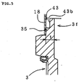
- the annular groove 43 may be formed in a manner as shown in FIG. 5. That is, the rear end portion of the metallic shell 3 is fitted into the outer cylinder 18. An annular cutout 43b is formed, and the groove 43 is defined by the outer cylinder 18 and the cutout 43b (in place of the cutout 43b, groove-shaped depressions may be formed at predetermined intervals in the circumferential direction).
- the metallic shell 3 and the outer cylinder 18 are connected through a welding portion 35 (or caulking portion) formed along the circumferential direction. This configuration is effective in the case where the thin-walled portion 3f of the metallic shell 3 in which the annular groove 43 is to be formed has a relatively small thickness t.
- the sensor element 2 has an elongated shape with a sensing portion D formed at a tip end thereof and is inserted through the metallic shell 3 such that the sensing portion D projects therefrom.
- the cushion layer 34 which is in contact with the front end of the sealing-material layer 32 (hereinafter referred to as the "front cushion layer") contains filler particles which are superior in heat resistance to glass contained in the sealing-material layer 32, as well as binder particles which partially fill gaps among filler particles, are superior in heat resistance to glass contained in the sealing-material layer 32, and are lower in softening temperature than the filler particles.
- the front cushion layer 34 is more susceptible to high temperature than is the sealing-material layer 32. Therefore, in the front cushion layer 34, the filler particles, which are superior in heat resistance to glass contained in the sealing-material layer 32, are bonded by the binder particles, which are lower in softening temperature than the filler particles but are superior in heat resistance to glass contained in the sealing-material layer. Accordingly, sufficient heat resistance is attained.
- the filler particles may be formed mainly of Al 2 O 3 or talc, and are preferably formed mainly of Al 2 O 3 in view of its excellent heat resistance.
- the binder particles are preferably of clay, for example, since clay particles can fuse together at a temperature of forming the sealing-material layer 32 (a sealing temperature).
- the rear cushion layer 33 does not have to be formed of a material having a high heat resistance, such as a material containing Al 2 O 3 as a main component, and may be formed of talc or the like.
- a material having a high heat resistance such as a material containing Al 2 O 3 as a main component
- glass having a softening temperature lower than that of glass used in the sealing-material layer 32 may be used as a binder. The use of such glass enables stable formation of the rear cushion layer 33, while avoiding a possibility that the sealing-material layer 32 re-melts due to heat treatment for fusing the rear cushion layer 33.
- annular groove 43 that surrounds the sealing-material layer 32 is formed in the metallic shell 3 by cutting out a portion of the metallic shell 3.
- the annular groove 43 is located between the inner surface of the outer cylinder and the surface of the cavity 31 of the metallic shell 3.
- the annular groove 43 serves as a heat-insulating layer. Also, when the sensor is subjected to a mechanical impulsive force caused by impinging foreign matter such as a pebble, a portion of the outer cylinder or a portion of the metallic shell which serves as an outer wall portion defining the annular groove 43 acts as a cushion for absorbing the mechanical impulsive force. Therefore, the annular groove 43 mitigates the thermal or mechanical shock acting on the sealing-material layer 32, so that the effect of the present invention can be enhanced.
- the gas sensor assumes the configuration of a sensor, which employs only an oxygen concentration cell element as a sensor element (ceramic element).
- the sensor element may be of a different type, such as a full-range oxygen sensor element or an NOx sensor element.
Landscapes
- Chemical & Material Sciences (AREA)
- Life Sciences & Earth Sciences (AREA)
- Health & Medical Sciences (AREA)
- Physics & Mathematics (AREA)
- Chemical Kinetics & Catalysis (AREA)
- Electrochemistry (AREA)
- Molecular Biology (AREA)
- Analytical Chemistry (AREA)
- Biochemistry (AREA)
- General Health & Medical Sciences (AREA)
- General Physics & Mathematics (AREA)
- Immunology (AREA)
- Pathology (AREA)
- Measuring Oxygen Concentration In Cells (AREA)
Applications Claiming Priority (4)
| Application Number | Priority Date | Filing Date | Title |
|---|---|---|---|
| JP36754697 | 1997-12-26 | ||
| JP36754697 | 1997-12-26 | ||
| JP35848198A JP3786330B2 (ja) | 1997-12-26 | 1998-12-17 | ガスセンサ |
| JP35848198 | 1998-12-17 |
Publications (3)
| Publication Number | Publication Date |
|---|---|
| EP0926489A2 true EP0926489A2 (de) | 1999-06-30 |
| EP0926489A3 EP0926489A3 (de) | 2000-12-27 |
| EP0926489B1 EP0926489B1 (de) | 2009-03-18 |
Family
ID=26580793
Family Applications (1)
| Application Number | Title | Priority Date | Filing Date |
|---|---|---|---|
| EP98310731A Expired - Lifetime EP0926489B1 (de) | 1997-12-26 | 1998-12-24 | Gassensor |
Country Status (4)
| Country | Link |
|---|---|
| US (1) | US6550309B1 (de) |
| EP (1) | EP0926489B1 (de) |
| JP (1) | JP3786330B2 (de) |
| DE (1) | DE69840665D1 (de) |
Cited By (4)
| Publication number | Priority date | Publication date | Assignee | Title |
|---|---|---|---|---|
| EP1167961A3 (de) * | 2000-06-30 | 2004-04-21 | Denso Corporation | Gassensor und zugehöriges Herstellungsverfahren |
| EP1120645A3 (de) * | 2000-01-27 | 2004-07-07 | Ngk Spark Plug Co., Ltd. | Gassensor |
| DE102007021916A1 (de) | 2007-05-10 | 2008-11-20 | Robert Bosch Gmbh | Gassensor |
| WO2020169299A1 (de) | 2019-02-18 | 2020-08-27 | Robert Bosch Gmbh | Lambdasonde |
Families Citing this family (9)
| Publication number | Priority date | Publication date | Assignee | Title |
|---|---|---|---|---|
| DE10225150A1 (de) * | 2002-06-06 | 2004-01-15 | Robert Bosch Gmbh | Gasmessfühler |
| US7341650B2 (en) * | 2003-06-27 | 2008-03-11 | Ngk Spark Plug Co., Ltd. | Method of manufacturing sensor and sensor |
| JP2006300920A (ja) * | 2005-03-23 | 2006-11-02 | Denso Corp | ガスセンサ |
| JP2010019833A (ja) * | 2008-06-11 | 2010-01-28 | Hitachi Ltd | ガスセンサ、酸素センサ及び空燃比制御システム |
| US9816960B2 (en) * | 2014-06-06 | 2017-11-14 | Delphi Technologies, Inc. | Gas sensor and method of making |
| US9557197B2 (en) * | 2014-06-06 | 2017-01-31 | Delphi Technologies, Inc. | Gas sensor with a seal and method of making |
| JP6414449B2 (ja) * | 2014-11-20 | 2018-10-31 | 株式会社デンソー | ガスセンサ |
| US10190895B2 (en) * | 2015-03-16 | 2019-01-29 | Ngk Insulators, Ltd. | Method for assembling gas sensor, and gas sensor assembly apparatus |
| JP6981913B2 (ja) * | 2018-04-09 | 2021-12-17 | 日本特殊陶業株式会社 | センサ |
Family Cites Families (26)
| Publication number | Priority date | Publication date | Assignee | Title |
|---|---|---|---|---|
| BE793162A (fr) * | 1971-12-23 | 1973-06-21 | Uss Eng & Consult | Detecteurs d'oxygene |
| US3920172A (en) | 1974-10-03 | 1975-11-18 | Bendix Corp | Conductive glass seal assembly |
| US4040930A (en) | 1976-02-05 | 1977-08-09 | Uop Inc. | Oxygen sensor |
| DE2937048C2 (de) * | 1979-09-13 | 1986-12-04 | Robert Bosch Gmbh, 7000 Stuttgart | Elektrochemischer Meßfühler für die Bestimmung des Sauerstoffgehaltes in Gasen, insbesondere in Abgasen von Brennkraftmaschinen |
| DE3206903A1 (de) * | 1982-02-26 | 1983-09-15 | Bosch Gmbh Robert | Gassensor, insbesondere fuer abgase von brennkraftmaschinen |
| JPS60211345A (ja) | 1984-04-06 | 1985-10-23 | Ngk Spark Plug Co Ltd | 高温で使用するセンサーのセラミック基板の端子構造 |
| JPS6193944A (ja) * | 1984-10-13 | 1986-05-12 | Ngk Spark Plug Co Ltd | ガス検出素子 |
| JPH021540A (ja) | 1988-02-12 | 1990-01-05 | Ngk Insulators Ltd | 酸素センサの端子構造 |
| JP2618678B2 (ja) * | 1988-04-09 | 1997-06-11 | 日本特殊陶業株式会社 | ガスセンサ |
| US5202154A (en) * | 1988-09-19 | 1993-04-13 | Ngk Spark Plug Co., Ltd. | Method of producing thick-film gas sensor element having improved stability |
| JP2514701B2 (ja) * | 1988-12-02 | 1996-07-10 | 日本特殊陶業株式会社 | 酸素センサ |
| JPH02146364U (de) * | 1989-05-15 | 1990-12-12 | ||
| JPH03257357A (ja) * | 1990-03-07 | 1991-11-15 | Ngk Spark Plug Co Ltd | センサの組付構造 |
| US5302274A (en) * | 1990-04-16 | 1994-04-12 | Minitech Co. | Electrochemical gas sensor cells using three dimensional sensing electrodes |
| JPH0754852Y2 (ja) * | 1990-10-03 | 1995-12-18 | 日本碍子株式会社 | 酸素センサ |
| JP2531891B2 (ja) * | 1991-03-20 | 1996-09-04 | 日本碍子株式会社 | セラミック体の欠陥検出方法 |
| US5282419A (en) | 1992-02-29 | 1994-02-01 | Koenig & Bauer Aktiengesellschaft | Ink roller |
| US5329806A (en) * | 1993-05-11 | 1994-07-19 | General Motors Corporation | Exhaust sensor with tubular shell |
| US5467636A (en) * | 1994-09-27 | 1995-11-21 | General Motors Corporation | Flat plate sensor with a robust package design |
| EP0704697A1 (de) | 1994-09-27 | 1996-04-03 | General Motors Corporation | Abgassensor mit keramischem Rohr in einer Metalltubepackung |
| DE19532090C2 (de) * | 1995-08-30 | 1997-09-18 | Bosch Gmbh Robert | Dichtung für ein Sensorelement eines Gassensors |
| DE19603379A1 (de) * | 1996-01-31 | 1997-08-07 | Bosch Gmbh Robert | Gassensor |
| US5739414A (en) * | 1996-02-12 | 1998-04-14 | General Motors Corporation | Sensor with glass seal |
| DE19608543A1 (de) * | 1996-03-06 | 1997-09-11 | Bosch Gmbh Robert | Meßfühler |
| JP3529538B2 (ja) * | 1996-03-25 | 2004-05-24 | 日本特殊陶業株式会社 | センサーおよびその製造方法 |
| JPH10253578A (ja) | 1997-03-06 | 1998-09-25 | Nippon Soken Inc | ガスセンサ |
-
1998
- 1998-12-17 JP JP35848198A patent/JP3786330B2/ja not_active Expired - Fee Related
- 1998-12-23 US US09/219,823 patent/US6550309B1/en not_active Expired - Lifetime
- 1998-12-24 EP EP98310731A patent/EP0926489B1/de not_active Expired - Lifetime
- 1998-12-24 DE DE69840665T patent/DE69840665D1/de not_active Expired - Lifetime
Cited By (4)
| Publication number | Priority date | Publication date | Assignee | Title |
|---|---|---|---|---|
| EP1120645A3 (de) * | 2000-01-27 | 2004-07-07 | Ngk Spark Plug Co., Ltd. | Gassensor |
| EP1167961A3 (de) * | 2000-06-30 | 2004-04-21 | Denso Corporation | Gassensor und zugehöriges Herstellungsverfahren |
| DE102007021916A1 (de) | 2007-05-10 | 2008-11-20 | Robert Bosch Gmbh | Gassensor |
| WO2020169299A1 (de) | 2019-02-18 | 2020-08-27 | Robert Bosch Gmbh | Lambdasonde |
Also Published As
| Publication number | Publication date |
|---|---|
| DE69840665D1 (de) | 2009-04-30 |
| JP3786330B2 (ja) | 2006-06-14 |
| JPH11242015A (ja) | 1999-09-07 |
| US6550309B1 (en) | 2003-04-22 |
| EP0926489B1 (de) | 2009-03-18 |
| EP0926489A3 (de) | 2000-12-27 |
Similar Documents
| Publication | Publication Date | Title |
|---|---|---|
| US6418777B1 (en) | Gas sensor | |
| EP0926489B1 (de) | Gassensor | |
| EP0939314B1 (de) | Gassensor | |
| US4418661A (en) | Glow plug, particularly for diesel engine | |
| EP0415356B1 (de) | Abgasreinigungsvorrichtung für Brennkraftmaschinen | |
| US6724133B2 (en) | Spark plug with nickel alloy electrode base material | |
| US7454949B2 (en) | Gas sensor and method for production thereof | |
| GB1566244A (en) | Oxygen sensing device and method of forming same | |
| JP6510405B2 (ja) | 温度センサ | |
| JP4739042B2 (ja) | ガスセンサ及びその製造方法 | |
| JP3800798B2 (ja) | 温度センサ素子 | |
| KR100416730B1 (ko) | 글로플러그 | |
| JP2002195560A (ja) | グロープラグ | |
| KR100899718B1 (ko) | 내연기관용 점화플러그 및 그 제조방법 | |
| US4251342A (en) | Solid electrolyte oxygen sensor with integral heater | |
| JP3529538B2 (ja) | センサーおよびその製造方法 | |
| JP4426084B2 (ja) | ガスセンサ | |
| JP4624548B2 (ja) | ガスセンサ | |
| JP6988850B2 (ja) | ガスセンサの製造方法 | |
| JP2007163272A (ja) | ガスセンサ | |
| CN120659184A (zh) | 陶瓷加热器 | |
| KR100493144B1 (ko) | 산소센서및그제조방법 | |
| JP2006266912A (ja) | ガスセンサ | |
| JPH0222895B2 (de) | ||
| JP2002228623A (ja) | ガスセンサ |
Legal Events
| Date | Code | Title | Description |
|---|---|---|---|
| PUAI | Public reference made under article 153(3) epc to a published international application that has entered the european phase |
Free format text: ORIGINAL CODE: 0009012 |
|
| AK | Designated contracting states |
Kind code of ref document: A2 Designated state(s): DE FR GB IT |
|
| AX | Request for extension of the european patent |
Free format text: AL;LT;LV;MK;RO;SI |
|
| PUAL | Search report despatched |
Free format text: ORIGINAL CODE: 0009013 |
|
| AK | Designated contracting states |
Kind code of ref document: A3 Designated state(s): AT BE CH CY DE DK ES FI FR GB GR IE IT LI LU MC NL PT SE |
|
| AX | Request for extension of the european patent |
Free format text: AL;LT;LV;MK;RO;SI |
|
| 17P | Request for examination filed |
Effective date: 20010405 |
|
| AKX | Designation fees paid |
Free format text: DE FR GB IT |
|
| 17Q | First examination report despatched |
Effective date: 20060907 |
|
| GRAP | Despatch of communication of intention to grant a patent |
Free format text: ORIGINAL CODE: EPIDOSNIGR1 |
|
| GRAS | Grant fee paid |
Free format text: ORIGINAL CODE: EPIDOSNIGR3 |
|
| GRAA | (expected) grant |
Free format text: ORIGINAL CODE: 0009210 |
|
| AK | Designated contracting states |
Kind code of ref document: B1 Designated state(s): DE FR GB IT |
|
| REG | Reference to a national code |
Ref country code: GB Ref legal event code: FG4D |
|
| REF | Corresponds to: |
Ref document number: 69840665 Country of ref document: DE Date of ref document: 20090430 Kind code of ref document: P |
|
| PLBE | No opposition filed within time limit |
Free format text: ORIGINAL CODE: 0009261 |
|
| STAA | Information on the status of an ep patent application or granted ep patent |
Free format text: STATUS: NO OPPOSITION FILED WITHIN TIME LIMIT |
|
| 26N | No opposition filed |
Effective date: 20091221 |
|
| PGFP | Annual fee paid to national office [announced via postgrant information from national office to epo] |
Ref country code: FR Payment date: 20101224 Year of fee payment: 13 |
|
| PGFP | Annual fee paid to national office [announced via postgrant information from national office to epo] |
Ref country code: IT Payment date: 20101224 Year of fee payment: 13 Ref country code: GB Payment date: 20101222 Year of fee payment: 13 |
|
| PGFP | Annual fee paid to national office [announced via postgrant information from national office to epo] |
Ref country code: DE Payment date: 20101222 Year of fee payment: 13 |
|
| GBPC | Gb: european patent ceased through non-payment of renewal fee |
Effective date: 20111224 |
|
| REG | Reference to a national code |
Ref country code: FR Ref legal event code: ST Effective date: 20120831 |
|
| REG | Reference to a national code |
Ref country code: DE Ref legal event code: R119 Ref document number: 69840665 Country of ref document: DE Effective date: 20120703 |
|
| PG25 | Lapsed in a contracting state [announced via postgrant information from national office to epo] |
Ref country code: DE Free format text: LAPSE BECAUSE OF NON-PAYMENT OF DUE FEES Effective date: 20120703 Ref country code: GB Free format text: LAPSE BECAUSE OF NON-PAYMENT OF DUE FEES Effective date: 20111224 |
|
| PG25 | Lapsed in a contracting state [announced via postgrant information from national office to epo] |
Ref country code: IT Free format text: LAPSE BECAUSE OF NON-PAYMENT OF DUE FEES Effective date: 20111224 |
|
| PG25 | Lapsed in a contracting state [announced via postgrant information from national office to epo] |
Ref country code: FR Free format text: LAPSE BECAUSE OF NON-PAYMENT OF DUE FEES Effective date: 20120102 |