EP0926489A2 - Gas sensor - Google Patents
Gas sensor Download PDFInfo
- Publication number
- EP0926489A2 EP0926489A2 EP98310731A EP98310731A EP0926489A2 EP 0926489 A2 EP0926489 A2 EP 0926489A2 EP 98310731 A EP98310731 A EP 98310731A EP 98310731 A EP98310731 A EP 98310731A EP 0926489 A2 EP0926489 A2 EP 0926489A2
- Authority
- EP
- European Patent Office
- Prior art keywords
- sealing
- material layer
- sensor
- metallic shell
- sensor element
- Prior art date
- Legal status (The legal status is an assumption and is not a legal conclusion. Google has not performed a legal analysis and makes no representation as to the accuracy of the status listed.)
- Granted
Links
Images


Classifications
-
- G—PHYSICS
- G01—MEASURING; TESTING
- G01N—INVESTIGATING OR ANALYSING MATERIALS BY DETERMINING THEIR CHEMICAL OR PHYSICAL PROPERTIES
- G01N27/00—Investigating or analysing materials by the use of electric, electrochemical, or magnetic means
- G01N27/26—Investigating or analysing materials by the use of electric, electrochemical, or magnetic means by investigating electrochemical variables; by using electrolysis or electrophoresis
- G01N27/403—Cells and electrode assemblies
- G01N27/406—Cells and probes with solid electrolytes
- G01N27/407—Cells and probes with solid electrolytes for investigating or analysing gases
Definitions
- the present invention relates to a gas sensor, such as an oxygen sensor, an HC sensor, or an NOx sensor, for detecting a component of an exhaust gas emitted from, especially, a motorcycle.
- a gas sensor such as an oxygen sensor, an HC sensor, or an NOx sensor
- a gas sensor composed of an outer cylinder, a metallic shell disposed inside the outer cylinder, and a sensor element disposed inside the metallic shell for detecting a component of a measurement gas.
- a gap between the outer surface of the sensor element and the inner surface of the metallic shell is generally filled with a sealing-material layer, as of glass.
- an oxygen sensor for automobile use is often mounted in an exhaust manifold or an exhaust pipe located near a suspension system and tires.
- a stone flipped from a tire may hit the sensor so that a mechanical shock acts on the sensor, or the sensor may be subjected to a strong thermal shock caused by splashing of water during exposure to high temperature.
- the sensor element of the sensor has a coefficient of thermal expansion smaller than that of the sealing-material layer. Therefore, in a glass sealing step, the sensor element receives a radial compressive force due to a thermal history (heating/cooling), so that stress concentration occurs in a boundary region between a portion of the sensor element covered with the sealing-material layer and an uncovered portion.
- a mechanical shock caused by a flipped stone or the like or a thermal shock caused by splashing of water acts on the sensor in such a state
- a resultant stress acts at a boundary region (hereinafter referred to as "sealing boundary portion") between the portion of the sensor element covered with the sealing-material layer and the uncovered portion, so that the sensor element is easily broken.
- an oxygen sensor used in a motorcycle is placed in an environment in which the oxygen sensor is likely to receive such shocks.
- An object of the present invention is to provide a gas sensor in which stress caused by application of a mechanical or thermal shock on the sensor does not concentrate at the sealing boundary portion and which therefore has excellent durability.
- a gas sensor of the present invention comprises an outer cylinder, a metallic shell, a sensor element, a sealing-material layer, and two cushion layers.
- the metallic shell is joined to the outer cylinder.
- the sensor element is disposed inside the metallic shell and is adapted to detect a component of a measurement gas.
- the sealing-material layer is mainly made of glass and is disposed between the inner surface of the metallic shell and the outer surface of the sensor element.
- the first cushion layer is disposed in contact with the end surface of the sealing-material layer located on a front-end side with respect to the axial direction of the sensor element.
- the first cushion layer is formed of a mixture containing filler particles which are superior in heat resistance to glass contained in the sealing-material layer, and binder particles which are superior in heat resistance to glass contained in the sealing-material layer and are lower in softening temperature than the filler particles.
- the second cushion layer is disposed in contact with the end surface of the sealing-material layer located on a rear-end side with respect to the axial direction of the sensor element.
- the second cushion layer is formed of a porous material containing glass whose softening temperature is slightly lower than that of the glass contained in the sealing-material layer.
- the above-described structure of the gas sensor of the present invention prevents local application of a strong bending stress onto the sealing boundary portion, which would otherwise occur when mechanical or thermal shock acts on the sensor element.
- the above-described effect of mitigating stress concentration can be achieved even when the cushion layer is disposed on only one side of the sealing-material layer.
- a gas sensor is used in an environment in which a strong mechanical or thermal shock may act on the sensor. Therefore, if the cushion layer is disposed on only one side of the sealing-material layer, the sensor does not meet the shock resistance required for application to motorcycles. When the cushion layer is disposed on both sides of the sealing-material layer, the sensor can sufficiently meet the shock resistance required for application to motorcycles.
- FIG. 1 shows an embodiment of a gas sensor of the present invention.
- An oxygen sensor 1 is adapted to detect the concentration of oxygen contained in an exhaust gas emitted from a motorcycle.
- the oxygen sensor 1 includes an elongated ceramic element 2 (sensor element). The tip of the ceramic element 2 is exposed to high-temperature exhaust gas flowing through an exhaust pipe.
- the ceramic element 2 is an elongated sheet having a rectangular section. As shown in FIG. 2, the ceramic element 2 is a laminate of an oxygen concentration cell element 2a and a heater 2b.
- the oxygen concentration cell element 2a has an elongated sheet form.
- the heater 2b also has an elongated sheet form and is adapted to heat the oxygen concentration cell element 2a to a predetermined activation temperature.
- the oxygen concentration cell element 2a is made of an oxygen-ion conductive solid electrolyte 21.
- a typical example of such a solid electrolyte 21 is ZrO 2 obtained through solid solution of Y 2 O 3 or CaO. Alternatively, a solid solution of ZrO 2 and an oxide of an alkali earth metal or rare earth metal may be used.
- the heater 2b is a known ceramic heater composed of a ceramic substrate 22 and a resistance-heating pattern 23.
- the resistance-heating pattern 23 is made of a high-melting-point metal and is embedded in the ceramic substrate 22.
- the ceramic element 2 having the above structure is inserted through a through-hole 30 of the metallic shell 3 and is fixed to the metallic shell 3.
- a cavity 31 is formed in the metallic shell 3 such that one end of the cavity 31 communicates with the rear end of the through-hole 30, and the other end of the cavity 31 opens at the rear end surface of the metallic shell 3.
- the cavity 31 has a diameter larger than that of the through-hole 30.
- a space which is defined by the outer surface of the ceramic element 2 and the inner surface of the metallic shell 3 which defines the cavity 31 is filled for sealing purpose with a sealing-material layer 32.
- the sealing-material layer 32 is mainly made of glass (for example, crystallized zinc silica boric-acid glass; softening temperature 684°C).
- cushion layers 33 and 34 are formed on opposite sides of the sealing-material layer 32.
- the cushion layers 33 and 34 are made of a porous inorganic substance.
- the porous inorganic substance for the front cushion layer 34 includes filler particles formed mainly of Al 2 O 3 , and the binder particles formed of clay.
- the clay particles may be mainly composed of hydrous alumino-silicate.
- the clay particles may be mainly composed two or more clay minerals (or their composite substances) selected from the group consisting of allophane, imogolite, hisingerite, smectites, kaolinite, halloysite, montmorillonite, illite, vermiculite, and dolomite.
- the clay particles may contain SiO 2 and Al 2 O 3 and, as needed, may further contain singly or in combination Fe 2 O 3 , TiO 2 , CaO, MgO, Na 2 O, and K 2 O.
- the clay particles contain 84% by weight Al 2 O 3 and 10% by weight SiO 2 as oxides and kaolinite and dolomite in appropriate amounts.
- the rear cushion layer 33 is formed of talc particles and crystallized glass having a softening temperature slightly lower than that of glass contained in the sealing-material layer 32 (e.g., crystallized zinc silica boric-acid glass; softening temperature 680°C).
- the above-mentioned sealed structure of the ceramic element 2 and the metallic shell 3 is manufactured in the following manner, for example.
- a material powder compact for forming the cushion layer 34 is manufactured.
- Al 2 O 3 powder serving as the filler particles and clay powder serving as the binder particles are mixed.
- the resulting mixture is pressed into a powder compact 50 shown in FIG. 4.
- the powder compact 50 has a through-hole 50b formed in a central portion thereof and in the axial direction thereof.
- the ceramic element 2 is inserted through the through-hole 50b formed in the powder compact 50. Then, the ceramic element 2 is inserted from its tip through the through-hole 30 formed in the metallic shell 3.
- the powder compact 50 is placed in the cavity 31 of the metallic shell 3 and is lightly pressed against the metallic shell 3 in the axial direction of the ceramic element 2.
- an inorganic material powder which is mainly composed of glass is formed into a cylindrical shape, yielding a powder compact.
- the powder compact is fitted onto the ceramic element 2 from the rear end of the ceramic element 2 in such a manner that the ceramic element 2 is inserted through a through-hole formed in the powder compact.
- the powder compact is placed in the cavity 31 adjacent to the powder compact 50, thereby obtaining an insulator-sensor-element assembly.
- the insulator-sensor-element assembly is heated to 850°C.
- the powder compact becomes the sealing-material layer 32 through fusion of the inorganic material powder which is mainly composed of glass, thereby sealing the ceramic element 2 against the metallic shell 3.
- the powder compact 50 becomes the cushion layer 34 through fusion of the clay powder while Al 2 O 3 particles are dispersed.
- a material powder (in the present embodiment, a mixed powder of talc and the above-described crystallized zinc silica boric-acid glass) for the cushion layer 33 is filled into a space between the ceramic element 2 and the metallic shell 3 at a rear portion of the cavity 31.
- the charged material powder is lightly pressed.
- the insulator-sensor-element assembly is again heated to 800°C.
- the charged material powder becomes the cushion layer 33 through fusion of the crystallized glass powder.
- the material powder may be pressed into a compact, which is then placed in the cavity 31.
- a protection cover 6 is fixedly attached to the tip portion of the metallic shell 3 through laser welding or resistance welding (for example, spot welding) in such a manner as to cover a projected portion of the ceramic element 2.
- a rear end portion of the metallic shell 3 is fitted into a tip end portion of an outer cylinder 18.
- the metallic shell 3 and the outer cylinder 18 are circumferentially welded together (for example, through laser welding).
- the metallic shell 3 and the outer cylinder 18 may be connected through circumferential caulking in place of laser welding.
- the oxygen sensor 1 is often attached to an exhaust manifold or an exhaust pipe located near a suspension system and tires of a vehicle. In this case, a flipped stone or the like may hit the sensor, or the sensor may be subjected to a strong thermal shock caused by splashing of water during exposure to high temperature.
- the cavity 31 is merely filled with the sealing-material layer 32 which is mainly composed of glass.
- the cushion layers 33 and 34 made of a porous inorganic substance are disposed on opposite sides of the sealing-material layer 32 with respect to the axial direction of the ceramic element 2. Accordingly, even when the force of a mechanical or thermal shock acts on the ceramic element 2, stress concentration is less likely to occur in the above-mentioned boundary region, so that breakage of the ceramic element 2 hardly occurs. In this case, since the cushion layers 33 and 34 support the portions of the ceramic element 2 which are not covered with the sealing-material layer 32, stress can be dispersed which would otherwise concentrate at the sealing boundary portion.
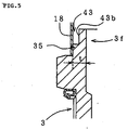
- annular groove 43 that surrounds the sealing-material layer 32 is formed in the metallic shell 3 by cutting out a portion of the metallic shell 3 and is located between the surface of the cavity 31 and the inner surface of the outer cylinder 18.
- a bottom 43a of the groove 43 is located beyond the sealing-material layer 32 toward the tip of the ceramic element 2 with respect to the axial direction of the ceramic element 2.
- the annular groove 43 may be formed in a manner as shown in FIG. 5. That is, the rear end portion of the metallic shell 3 is fitted into the outer cylinder 18. An annular cutout 43b is formed, and the groove 43 is defined by the outer cylinder 18 and the cutout 43b (in place of the cutout 43b, groove-shaped depressions may be formed at predetermined intervals in the circumferential direction).
- the metallic shell 3 and the outer cylinder 18 are connected through a welding portion 35 (or caulking portion) formed along the circumferential direction. This configuration is effective in the case where the thin-walled portion 3f of the metallic shell 3 in which the annular groove 43 is to be formed has a relatively small thickness t.
- the sensor element 2 has an elongated shape with a sensing portion D formed at a tip end thereof and is inserted through the metallic shell 3 such that the sensing portion D projects therefrom.
- the cushion layer 34 which is in contact with the front end of the sealing-material layer 32 (hereinafter referred to as the "front cushion layer") contains filler particles which are superior in heat resistance to glass contained in the sealing-material layer 32, as well as binder particles which partially fill gaps among filler particles, are superior in heat resistance to glass contained in the sealing-material layer 32, and are lower in softening temperature than the filler particles.
- the front cushion layer 34 is more susceptible to high temperature than is the sealing-material layer 32. Therefore, in the front cushion layer 34, the filler particles, which are superior in heat resistance to glass contained in the sealing-material layer 32, are bonded by the binder particles, which are lower in softening temperature than the filler particles but are superior in heat resistance to glass contained in the sealing-material layer. Accordingly, sufficient heat resistance is attained.
- the filler particles may be formed mainly of Al 2 O 3 or talc, and are preferably formed mainly of Al 2 O 3 in view of its excellent heat resistance.
- the binder particles are preferably of clay, for example, since clay particles can fuse together at a temperature of forming the sealing-material layer 32 (a sealing temperature).
- the rear cushion layer 33 does not have to be formed of a material having a high heat resistance, such as a material containing Al 2 O 3 as a main component, and may be formed of talc or the like.
- a material having a high heat resistance such as a material containing Al 2 O 3 as a main component
- glass having a softening temperature lower than that of glass used in the sealing-material layer 32 may be used as a binder. The use of such glass enables stable formation of the rear cushion layer 33, while avoiding a possibility that the sealing-material layer 32 re-melts due to heat treatment for fusing the rear cushion layer 33.
- annular groove 43 that surrounds the sealing-material layer 32 is formed in the metallic shell 3 by cutting out a portion of the metallic shell 3.
- the annular groove 43 is located between the inner surface of the outer cylinder and the surface of the cavity 31 of the metallic shell 3.
- the annular groove 43 serves as a heat-insulating layer. Also, when the sensor is subjected to a mechanical impulsive force caused by impinging foreign matter such as a pebble, a portion of the outer cylinder or a portion of the metallic shell which serves as an outer wall portion defining the annular groove 43 acts as a cushion for absorbing the mechanical impulsive force. Therefore, the annular groove 43 mitigates the thermal or mechanical shock acting on the sealing-material layer 32, so that the effect of the present invention can be enhanced.
- the gas sensor assumes the configuration of a sensor, which employs only an oxygen concentration cell element as a sensor element (ceramic element).
- the sensor element may be of a different type, such as a full-range oxygen sensor element or an NOx sensor element.
Abstract
Description
- The present invention relates to a gas sensor, such as an oxygen sensor, an HC sensor, or an NOx sensor, for detecting a component of an exhaust gas emitted from, especially, a motorcycle.
- Conventionally, there has been known a gas sensor composed of an outer cylinder, a metallic shell disposed inside the outer cylinder, and a sensor element disposed inside the metallic shell for detecting a component of a measurement gas. In a gas sensor having such a structure, a gap between the outer surface of the sensor element and the inner surface of the metallic shell is generally filled with a sealing-material layer, as of glass.
- For example, an oxygen sensor for automobile use is often mounted in an exhaust manifold or an exhaust pipe located near a suspension system and tires. In this case, a stone flipped from a tire may hit the sensor so that a mechanical shock acts on the sensor, or the sensor may be subjected to a strong thermal shock caused by splashing of water during exposure to high temperature. Further, the sensor element of the sensor has a coefficient of thermal expansion smaller than that of the sealing-material layer. Therefore, in a glass sealing step, the sensor element receives a radial compressive force due to a thermal history (heating/cooling), so that stress concentration occurs in a boundary region between a portion of the sensor element covered with the sealing-material layer and an uncovered portion. If a mechanical shock caused by a flipped stone or the like or a thermal shock caused by splashing of water acts on the sensor in such a state, a resultant stress acts at a boundary region (hereinafter referred to as "sealing boundary portion") between the portion of the sensor element covered with the sealing-material layer and the uncovered portion, so that the sensor element is easily broken. Especially, an oxygen sensor used in a motorcycle is placed in an environment in which the oxygen sensor is likely to receive such shocks.
- An object of the present invention is to provide a gas sensor in which stress caused by application of a mechanical or thermal shock on the sensor does not concentrate at the sealing boundary portion and which therefore has excellent durability.
- To achieve the above object, a gas sensor of the present invention comprises an outer cylinder, a metallic shell, a sensor element, a sealing-material layer, and two cushion layers. The metallic shell is joined to the outer cylinder. The sensor element is disposed inside the metallic shell and is adapted to detect a component of a measurement gas. The sealing-material layer is mainly made of glass and is disposed between the inner surface of the metallic shell and the outer surface of the sensor element. The first cushion layer is disposed in contact with the end surface of the sealing-material layer located on a front-end side with respect to the axial direction of the sensor element. The first cushion layer is formed of a mixture containing filler particles which are superior in heat resistance to glass contained in the sealing-material layer, and binder particles which are superior in heat resistance to glass contained in the sealing-material layer and are lower in softening temperature than the filler particles. The second cushion layer is disposed in contact with the end surface of the sealing-material layer located on a rear-end side with respect to the axial direction of the sensor element. The second cushion layer is formed of a porous material containing glass whose softening temperature is slightly lower than that of the glass contained in the sealing-material layer.
- The above-described structure of the gas sensor of the present invention prevents local application of a strong bending stress onto the sealing boundary portion, which would otherwise occur when mechanical or thermal shock acts on the sensor element.
- In general, the above-described effect of mitigating stress concentration can be achieved even when the cushion layer is disposed on only one side of the sealing-material layer. However, in the case of application to a motorcycle, a gas sensor is used in an environment in which a strong mechanical or thermal shock may act on the sensor. Therefore, if the cushion layer is disposed on only one side of the sealing-material layer, the sensor does not meet the shock resistance required for application to motorcycles. When the cushion layer is disposed on both sides of the sealing-material layer, the sensor can sufficiently meet the shock resistance required for application to motorcycles.
- The invention will be further described by way of example with reference to the accompanying drawings, in which:-
- Figure 1 is a longitudinal sectional view showing an embodiment of an oxygen sensor of the present invention;
- Figure 2 is an explanatory view showing the structure of a ceramic element serving as a sensor element of the sensor of FIG. 1;
- Figure 3 is an explanatory view showing the action of a cushion layer;
- Figure 4 is an explanatory view illustrating a process for manufacturing the oxygen sensor of FIG. 1; and
- Figure 5 is a longitudinal sectional view showing a modification of the annular groove formed in the metallic shell.
-
- Embodiments of the present invention will next be described with reference to drawings.
- FIG. 1 shows an embodiment of a gas sensor of the present invention. An
oxygen sensor 1 is adapted to detect the concentration of oxygen contained in an exhaust gas emitted from a motorcycle. Theoxygen sensor 1 includes an elongated ceramic element 2 (sensor element). The tip of theceramic element 2 is exposed to high-temperature exhaust gas flowing through an exhaust pipe. - The
ceramic element 2 is an elongated sheet having a rectangular section. As shown in FIG. 2, theceramic element 2 is a laminate of an oxygenconcentration cell element 2a and a heater 2b. The oxygenconcentration cell element 2a has an elongated sheet form. The heater 2b also has an elongated sheet form and is adapted to heat the oxygenconcentration cell element 2a to a predetermined activation temperature. The oxygenconcentration cell element 2a is made of an oxygen-ion conductivesolid electrolyte 21. A typical example of such asolid electrolyte 21 is ZrO2 obtained through solid solution of Y2O3 or CaO. Alternatively, a solid solution of ZrO2 and an oxide of an alkali earth metal or rare earth metal may be used. The heater 2b is a known ceramic heater composed of aceramic substrate 22 and a resistance-heating pattern 23. The resistance-heating pattern 23 is made of a high-melting-point metal and is embedded in theceramic substrate 22. - As shown in FIG. 1, the
ceramic element 2 having the above structure is inserted through a through-hole 30 of themetallic shell 3 and is fixed to themetallic shell 3. Acavity 31 is formed in themetallic shell 3 such that one end of thecavity 31 communicates with the rear end of the through-hole 30, and the other end of thecavity 31 opens at the rear end surface of themetallic shell 3. Thecavity 31 has a diameter larger than that of the through-hole 30. A space which is defined by the outer surface of theceramic element 2 and the inner surface of themetallic shell 3 which defines thecavity 31 is filled for sealing purpose with a sealing-material layer 32. The sealing-material layer 32 is mainly made of glass (for example, crystallized zinc silica boric-acid glass; softening temperature 684°C). - Within the
chamber 31,cushion layers material layer 32. Thecushion layers front cushion layer 34 includes filler particles formed mainly of Al2O3, and the binder particles formed of clay. - The clay particles may be mainly composed of hydrous alumino-silicate. For example, the clay particles may be mainly composed two or more clay minerals (or their composite substances) selected from the group consisting of allophane, imogolite, hisingerite, smectites, kaolinite, halloysite, montmorillonite, illite, vermiculite, and dolomite. From the point of view of oxide components, the clay particles may contain SiO2 and Al2O3 and, as needed, may further contain singly or in combination Fe2O3, TiO2, CaO, MgO, Na2O, and K2O. For example, in the present embodiment, the clay particles contain 84% by weight Al2O3 and 10% by weight SiO2 as oxides and kaolinite and dolomite in appropriate amounts.
- The
rear cushion layer 33 is formed of talc particles and crystallized glass having a softening temperature slightly lower than that of glass contained in the sealing-material layer 32 (e.g., crystallized zinc silica boric-acid glass; softening temperature 680°C). - The above-mentioned sealed structure of the
ceramic element 2 and themetallic shell 3 is manufactured in the following manner, for example. First, a material powder compact for forming thecushion layer 34 is manufactured. In the present embodiment, Al2O3 powder serving as the filler particles and clay powder serving as the binder particles are mixed. The resulting mixture is pressed into a powder compact 50 shown in FIG. 4. The powder compact 50 has a through-hole 50b formed in a central portion thereof and in the axial direction thereof. - Next, the
ceramic element 2 is inserted through the through-hole 50b formed in the powder compact 50. Then, theceramic element 2 is inserted from its tip through the through-hole 30 formed in themetallic shell 3. The powder compact 50 is placed in thecavity 31 of themetallic shell 3 and is lightly pressed against themetallic shell 3 in the axial direction of theceramic element 2. Next, an inorganic material powder which is mainly composed of glass is formed into a cylindrical shape, yielding a powder compact. The powder compact is fitted onto theceramic element 2 from the rear end of theceramic element 2 in such a manner that theceramic element 2 is inserted through a through-hole formed in the powder compact. Thus, the powder compact is placed in thecavity 31 adjacent to thepowder compact 50, thereby obtaining an insulator-sensor-element assembly. - The insulator-sensor-element assembly is heated to 850°C. As a result, the powder compact becomes the sealing-
material layer 32 through fusion of the inorganic material powder which is mainly composed of glass, thereby sealing theceramic element 2 against themetallic shell 3. Thepowder compact 50 becomes thecushion layer 34 through fusion of the clay powder while Al2O3 particles are dispersed. - Next, a material powder (in the present embodiment, a mixed powder of talc and the above-described crystallized zinc silica boric-acid glass) for the
cushion layer 33 is filled into a space between theceramic element 2 and themetallic shell 3 at a rear portion of thecavity 31. The charged material powder is lightly pressed. Subsequently, the insulator-sensor-element assembly is again heated to 800°C. As a result, the charged material powder becomes thecushion layer 33 through fusion of the crystallized glass powder. In place of directly filling the material powder into thecavity 31, the material powder may be pressed into a compact, which is then placed in thecavity 31. - Next, a
protection cover 6 is fixedly attached to the tip portion of themetallic shell 3 through laser welding or resistance welding (for example, spot welding) in such a manner as to cover a projected portion of theceramic element 2. A rear end portion of themetallic shell 3 is fitted into a tip end portion of anouter cylinder 18. At the fitted overlap of themetallic shell 3 and theouter cylinder 18, themetallic shell 3 and theouter cylinder 18 are circumferentially welded together (for example, through laser welding). At the fitted overlap, themetallic shell 3 and theouter cylinder 18 may be connected through circumferential caulking in place of laser welding. - The
oxygen sensor 1 is often attached to an exhaust manifold or an exhaust pipe located near a suspension system and tires of a vehicle. In this case, a flipped stone or the like may hit the sensor, or the sensor may be subjected to a strong thermal shock caused by splashing of water during exposure to high temperature. According to the configuration of a conventional oxygen sensor, as shown in FIG. 3(a), thecavity 31 is merely filled with the sealing-material layer 32 which is mainly composed of glass. For example, when a bending stress is applied to theceramic element 2 due to a shock caused by a flipped stone or thermal shock, stress concentration tends to occur in a boundary region between a portion of theceramic element 2 covered with the sealing-material layer 32 and an uncovered portion in the axial direction of theceramic element 2, causing a potential breakage of theceramic element 2. - By contrast, according to the above-described configuration of the
oxygen sensor 1 of the present invention, as shown in FIG. 3(b), the cushion layers 33 and 34 made of a porous inorganic substance are disposed on opposite sides of the sealing-material layer 32 with respect to the axial direction of theceramic element 2. Accordingly, even when the force of a mechanical or thermal shock acts on theceramic element 2, stress concentration is less likely to occur in the above-mentioned boundary region, so that breakage of theceramic element 2 hardly occurs. In this case, since the cushion layers 33 and 34 support the portions of theceramic element 2 which are not covered with the sealing-material layer 32, stress can be dispersed which would otherwise concentrate at the sealing boundary portion. - As shown in FIG. 1, an
annular groove 43 that surrounds the sealing-material layer 32 is formed in themetallic shell 3 by cutting out a portion of themetallic shell 3 and is located between the surface of thecavity 31 and the inner surface of theouter cylinder 18. A bottom 43a of thegroove 43 is located beyond the sealing-material layer 32 toward the tip of theceramic element 2 with respect to the axial direction of theceramic element 2. - The
annular groove 43 may be formed in a manner as shown in FIG. 5. That is, the rear end portion of themetallic shell 3 is fitted into theouter cylinder 18. Anannular cutout 43b is formed, and thegroove 43 is defined by theouter cylinder 18 and thecutout 43b (in place of thecutout 43b, groove-shaped depressions may be formed at predetermined intervals in the circumferential direction). Themetallic shell 3 and theouter cylinder 18 are connected through a welding portion 35 (or caulking portion) formed along the circumferential direction. This configuration is effective in the case where the thin-walled portion 3f of themetallic shell 3 in which theannular groove 43 is to be formed has a relatively small thickness t. - As shown in FIG. 1, the
sensor element 2 has an elongated shape with a sensing portion D formed at a tip end thereof and is inserted through themetallic shell 3 such that the sensing portion D projects therefrom. In this case, thecushion layer 34 which is in contact with the front end of the sealing-material layer 32 (hereinafter referred to as the "front cushion layer") contains filler particles which are superior in heat resistance to glass contained in the sealing-material layer 32, as well as binder particles which partially fill gaps among filler particles, are superior in heat resistance to glass contained in the sealing-material layer 32, and are lower in softening temperature than the filler particles. - Specifically, the
front cushion layer 34 is more susceptible to high temperature than is the sealing-material layer 32. Therefore, in thefront cushion layer 34, the filler particles, which are superior in heat resistance to glass contained in the sealing-material layer 32, are bonded by the binder particles, which are lower in softening temperature than the filler particles but are superior in heat resistance to glass contained in the sealing-material layer. Accordingly, sufficient heat resistance is attained. In this case, the filler particles may be formed mainly of Al2O3 or talc, and are preferably formed mainly of Al2O3 in view of its excellent heat resistance. The binder particles are preferably of clay, for example, since clay particles can fuse together at a temperature of forming the sealing-material layer 32 (a sealing temperature). - For the
cushion layer 33 which is in contact with the rear end of the sealing-material layer 32 (hereinafter referred to as the "rear cushion layer"), the requirement in relation to heat resistance is less stringent than that for thefront cushion layer 34. Therefore, therear cushion layer 33 does not have to be formed of a material having a high heat resistance, such as a material containing Al2O3 as a main component, and may be formed of talc or the like. Further, in place of clay particles, glass having a softening temperature lower than that of glass used in the sealing-material layer 32 may be used as a binder. The use of such glass enables stable formation of therear cushion layer 33, while avoiding a possibility that the sealing-material layer 32 re-melts due to heat treatment for fusing therear cushion layer 33. - In the
gas sensor 1 of the present invention, anannular groove 43 that surrounds the sealing-material layer 32 is formed in themetallic shell 3 by cutting out a portion of themetallic shell 3. Theannular groove 43 is located between the inner surface of the outer cylinder and the surface of thecavity 31 of themetallic shell 3. - In the above configuration, when the
sensor 1 is in a heated state and water is splashed thereon, thus causing an abrupt temperature variation, theannular groove 43 serves as a heat-insulating layer. Also, when the sensor is subjected to a mechanical impulsive force caused by impinging foreign matter such as a pebble, a portion of the outer cylinder or a portion of the metallic shell which serves as an outer wall portion defining theannular groove 43 acts as a cushion for absorbing the mechanical impulsive force. Therefore, theannular groove 43 mitigates the thermal or mechanical shock acting on the sealing-material layer 32, so that the effect of the present invention can be enhanced. - In the above embodiments, the gas sensor assumes the configuration of a sensor, which employs only an oxygen concentration cell element as a sensor element (ceramic element). However, the sensor element may be of a different type, such as a full-range oxygen sensor element or an NOx sensor element.
- 1:
- oxygen sensor (gas sensor)
- 2:
- ceramic sensor (sensor element)
- 3:
- metallic shell
- 4:
- insulator
- 18:
- outer cylinder
- 30:
- through-hole
- 31:
- cavity
- 32:
- sealing-material layer
- 33:
- rear cushion layer
- 34:
- front cushion layer
Claims (2)
- A gas sensor, comprising:an outer cylinder;a metallic shell joined to said outer cylinder;a sensor element disposed inside said metallic shell and adapted to detect a component of a measurement gas;a sealing-material layer mainly made of glass and disposed between an inner surface of said metallic shell and an outer surface of said sensor element;a first cushion layer disposed in contact with the end surface of said sealing-material layer located on a front-end side with respect to the axial direction of said sensor element, said first cushion layer being formed of a mixture containing filler particles which are superior in heat resistance to glass contained in said sealing-material layer, and binder particles which are superior in heat resistance to glass contained in said sealing-material layer and are lower in softening temperature than the filler particles; anda second cushion layer disposed in contact with the end surface of said sealing-material layer located on a rear-end side with respect to the axial direction of said sensor element, said second cushion layer being formed of a porous material containing glass whose softening temperature is slightly lower than that of the glass contained in said sealing-material layer.
- A gas sensor according to Claim 1, wherein the gas sensor is used in a motorcycle.
Applications Claiming Priority (4)
| Application Number | Priority Date | Filing Date | Title |
|---|---|---|---|
| JP36754697 | 1997-12-26 | ||
| JP36754697 | 1997-12-26 | ||
| JP35848198A JP3786330B2 (en) | 1997-12-26 | 1998-12-17 | Gas sensor |
| JP35848198 | 1998-12-17 |
Publications (3)
| Publication Number | Publication Date |
|---|---|
| EP0926489A2 true EP0926489A2 (en) | 1999-06-30 |
| EP0926489A3 EP0926489A3 (en) | 2000-12-27 |
| EP0926489B1 EP0926489B1 (en) | 2009-03-18 |
Family
ID=26580793
Family Applications (1)
| Application Number | Title | Priority Date | Filing Date |
|---|---|---|---|
| EP98310731A Expired - Lifetime EP0926489B1 (en) | 1997-12-26 | 1998-12-24 | Gas sensor |
Country Status (4)
| Country | Link |
|---|---|
| US (1) | US6550309B1 (en) |
| EP (1) | EP0926489B1 (en) |
| JP (1) | JP3786330B2 (en) |
| DE (1) | DE69840665D1 (en) |
Cited By (4)
| Publication number | Priority date | Publication date | Assignee | Title |
|---|---|---|---|---|
| EP1167961A3 (en) * | 2000-06-30 | 2004-04-21 | Denso Corporation | Gas sensor and manufacturing method for the same |
| EP1120645A3 (en) * | 2000-01-27 | 2004-07-07 | Ngk Spark Plug Co., Ltd. | Gas sensor |
| DE102007021916A1 (en) | 2007-05-10 | 2008-11-20 | Robert Bosch Gmbh | Gas sensor for e.g. determining temperature of exhaust gas of internal combustion engine, has support designed as metallic clamping element, which has two clamping sections, where sensor element is clamped between clamping sections |
| WO2020169299A1 (en) | 2019-02-18 | 2020-08-27 | Robert Bosch Gmbh | Lambda sensor |
Families Citing this family (9)
| Publication number | Priority date | Publication date | Assignee | Title |
|---|---|---|---|---|
| DE10225150A1 (en) * | 2002-06-06 | 2004-01-15 | Robert Bosch Gmbh | Gas sensor |
| US7341650B2 (en) * | 2003-06-27 | 2008-03-11 | Ngk Spark Plug Co., Ltd. | Method of manufacturing sensor and sensor |
| JP2006300920A (en) * | 2005-03-23 | 2006-11-02 | Denso Corp | Gas sensor |
| JP2010019833A (en) * | 2008-06-11 | 2010-01-28 | Hitachi Ltd | Gas sensor, oxygen sensor, and air/fuel ratio control system |
| US9816960B2 (en) * | 2014-06-06 | 2017-11-14 | Delphi Technologies, Inc. | Gas sensor and method of making |
| US9557197B2 (en) * | 2014-06-06 | 2017-01-31 | Delphi Technologies, Inc. | Gas sensor with a seal and method of making |
| JP6414449B2 (en) * | 2014-11-20 | 2018-10-31 | 株式会社デンソー | Gas sensor |
| US10190895B2 (en) * | 2015-03-16 | 2019-01-29 | Ngk Insulators, Ltd. | Method for assembling gas sensor, and gas sensor assembly apparatus |
| JP6981913B2 (en) * | 2018-04-09 | 2021-12-17 | 日本特殊陶業株式会社 | Sensor |
Citations (4)
| Publication number | Priority date | Publication date | Assignee | Title |
|---|---|---|---|---|
| US3920172A (en) * | 1974-10-03 | 1975-11-18 | Bendix Corp | Conductive glass seal assembly |
| US4040930A (en) * | 1976-02-05 | 1977-08-09 | Uop Inc. | Oxygen sensor |
| EP0624791A1 (en) * | 1993-05-11 | 1994-11-17 | General Motors Corporation | Exhaust sensor with tubular shell |
| EP0704697A1 (en) * | 1994-09-27 | 1996-04-03 | General Motors Corporation | Exhaust sensor including a ceramic tube in metal tube package |
Family Cites Families (22)
| Publication number | Priority date | Publication date | Assignee | Title |
|---|---|---|---|---|
| BE793162A (en) * | 1971-12-23 | 1973-06-21 | Uss Eng & Consult | OXYGEN DETECTORS |
| DE2937048C2 (en) * | 1979-09-13 | 1986-12-04 | Robert Bosch Gmbh, 7000 Stuttgart | Electrochemical measuring sensor for determining the oxygen content in gases, especially in exhaust gases from internal combustion engines |
| DE3206903A1 (en) * | 1982-02-26 | 1983-09-15 | Bosch Gmbh Robert | GAS SENSOR, ESPECIALLY FOR EXHAUST GAS FROM COMBUSTION ENGINES |
| JPS60211345A (en) | 1984-04-06 | 1985-10-23 | Ngk Spark Plug Co Ltd | Terminal structure of ceramic substrate |
| JPS6193944A (en) * | 1984-10-13 | 1986-05-12 | Ngk Spark Plug Co Ltd | Gas detecting element |
| JPH021540A (en) | 1988-02-12 | 1990-01-05 | Ngk Insulators Ltd | Terminal structure of oxygen sensor |
| JP2618678B2 (en) * | 1988-04-09 | 1997-06-11 | 日本特殊陶業株式会社 | Gas sensor |
| US5202154A (en) * | 1988-09-19 | 1993-04-13 | Ngk Spark Plug Co., Ltd. | Method of producing thick-film gas sensor element having improved stability |
| JP2514701B2 (en) * | 1988-12-02 | 1996-07-10 | 日本特殊陶業株式会社 | Oxygen sensor |
| JPH02146364U (en) * | 1989-05-15 | 1990-12-12 | ||
| JPH03257357A (en) * | 1990-03-07 | 1991-11-15 | Ngk Spark Plug Co Ltd | Sensor assembling structure |
| US5302274A (en) * | 1990-04-16 | 1994-04-12 | Minitech Co. | Electrochemical gas sensor cells using three dimensional sensing electrodes |
| JPH0754852Y2 (en) * | 1990-10-03 | 1995-12-18 | 日本碍子株式会社 | Oxygen sensor |
| JP2531891B2 (en) * | 1991-03-20 | 1996-09-04 | 日本碍子株式会社 | Defect detection method for ceramic body |
| US5282419A (en) | 1992-02-29 | 1994-02-01 | Koenig & Bauer Aktiengesellschaft | Ink roller |
| US5467636A (en) * | 1994-09-27 | 1995-11-21 | General Motors Corporation | Flat plate sensor with a robust package design |
| DE19532090C2 (en) * | 1995-08-30 | 1997-09-18 | Bosch Gmbh Robert | Seal for a sensor element of a gas sensor |
| DE19603379A1 (en) * | 1996-01-31 | 1997-08-07 | Bosch Gmbh Robert | Gas sensor |
| US5739414A (en) * | 1996-02-12 | 1998-04-14 | General Motors Corporation | Sensor with glass seal |
| DE19608543A1 (en) * | 1996-03-06 | 1997-09-11 | Bosch Gmbh Robert | Sensor |
| JP3529538B2 (en) * | 1996-03-25 | 2004-05-24 | 日本特殊陶業株式会社 | Sensor and manufacturing method thereof |
| JPH10253578A (en) | 1997-03-06 | 1998-09-25 | Nippon Soken Inc | Gas sensor |
-
1998
- 1998-12-17 JP JP35848198A patent/JP3786330B2/en not_active Expired - Fee Related
- 1998-12-23 US US09/219,823 patent/US6550309B1/en not_active Expired - Lifetime
- 1998-12-24 EP EP98310731A patent/EP0926489B1/en not_active Expired - Lifetime
- 1998-12-24 DE DE69840665T patent/DE69840665D1/en not_active Expired - Lifetime
Patent Citations (4)
| Publication number | Priority date | Publication date | Assignee | Title |
|---|---|---|---|---|
| US3920172A (en) * | 1974-10-03 | 1975-11-18 | Bendix Corp | Conductive glass seal assembly |
| US4040930A (en) * | 1976-02-05 | 1977-08-09 | Uop Inc. | Oxygen sensor |
| EP0624791A1 (en) * | 1993-05-11 | 1994-11-17 | General Motors Corporation | Exhaust sensor with tubular shell |
| EP0704697A1 (en) * | 1994-09-27 | 1996-04-03 | General Motors Corporation | Exhaust sensor including a ceramic tube in metal tube package |
Cited By (4)
| Publication number | Priority date | Publication date | Assignee | Title |
|---|---|---|---|---|
| EP1120645A3 (en) * | 2000-01-27 | 2004-07-07 | Ngk Spark Plug Co., Ltd. | Gas sensor |
| EP1167961A3 (en) * | 2000-06-30 | 2004-04-21 | Denso Corporation | Gas sensor and manufacturing method for the same |
| DE102007021916A1 (en) | 2007-05-10 | 2008-11-20 | Robert Bosch Gmbh | Gas sensor for e.g. determining temperature of exhaust gas of internal combustion engine, has support designed as metallic clamping element, which has two clamping sections, where sensor element is clamped between clamping sections |
| WO2020169299A1 (en) | 2019-02-18 | 2020-08-27 | Robert Bosch Gmbh | Lambda sensor |
Also Published As
| Publication number | Publication date |
|---|---|
| EP0926489B1 (en) | 2009-03-18 |
| JP3786330B2 (en) | 2006-06-14 |
| US6550309B1 (en) | 2003-04-22 |
| DE69840665D1 (en) | 2009-04-30 |
| EP0926489A3 (en) | 2000-12-27 |
| JPH11242015A (en) | 1999-09-07 |
Similar Documents
| Publication | Publication Date | Title |
|---|---|---|
| US6418777B1 (en) | Gas sensor | |
| EP0926489B1 (en) | Gas sensor | |
| EP0939314B1 (en) | Gas sensor | |
| US4418661A (en) | Glow plug, particularly for diesel engine | |
| EP0415356B1 (en) | Exhaust gas cleaning device for internal combustion engine | |
| US7168295B2 (en) | Gas sensor | |
| EP1189318B1 (en) | Spark plug | |
| JP4739042B2 (en) | Gas sensor and manufacturing method thereof | |
| JP4760584B2 (en) | Temperature sensor and manufacturing method thereof | |
| US20060162422A1 (en) | Gas sensor and method for production thereof | |
| GB1566244A (en) | Oxygen sensing device and method of forming same | |
| JP3800798B2 (en) | Temperature sensor element | |
| KR100416730B1 (en) | Glow plug | |
| JP6510405B2 (en) | Temperature sensor | |
| JP2002195560A (en) | Glow plug | |
| KR100899718B1 (en) | A spark plug for an internal combustion engine | |
| JP3529538B2 (en) | Sensor and manufacturing method thereof | |
| JP2007163272A (en) | Gas sensor | |
| JP4624548B2 (en) | Gas sensor | |
| JP2006090842A (en) | Gas sensor | |
| JP2006266912A (en) | Gas sensor | |
| JP4176942B2 (en) | Gas sensor | |
| JPH0222895B2 (en) | ||
| JPS602455Y2 (en) | Ceramic glow plug | |
| KR100493144B1 (en) | A sensor for measuring a exhaust gas and a manufacturing method thereof |
Legal Events
| Date | Code | Title | Description |
|---|---|---|---|
| PUAI | Public reference made under article 153(3) epc to a published international application that has entered the european phase |
Free format text: ORIGINAL CODE: 0009012 |
|
| AK | Designated contracting states |
Kind code of ref document: A2 Designated state(s): DE FR GB IT |
|
| AX | Request for extension of the european patent |
Free format text: AL;LT;LV;MK;RO;SI |
|
| PUAL | Search report despatched |
Free format text: ORIGINAL CODE: 0009013 |
|
| AK | Designated contracting states |
Kind code of ref document: A3 Designated state(s): AT BE CH CY DE DK ES FI FR GB GR IE IT LI LU MC NL PT SE |
|
| AX | Request for extension of the european patent |
Free format text: AL;LT;LV;MK;RO;SI |
|
| 17P | Request for examination filed |
Effective date: 20010405 |
|
| AKX | Designation fees paid |
Free format text: DE FR GB IT |
|
| 17Q | First examination report despatched |
Effective date: 20060907 |
|
| GRAP | Despatch of communication of intention to grant a patent |
Free format text: ORIGINAL CODE: EPIDOSNIGR1 |
|
| GRAS | Grant fee paid |
Free format text: ORIGINAL CODE: EPIDOSNIGR3 |
|
| GRAA | (expected) grant |
Free format text: ORIGINAL CODE: 0009210 |
|
| AK | Designated contracting states |
Kind code of ref document: B1 Designated state(s): DE FR GB IT |
|
| REG | Reference to a national code |
Ref country code: GB Ref legal event code: FG4D |
|
| REF | Corresponds to: |
Ref document number: 69840665 Country of ref document: DE Date of ref document: 20090430 Kind code of ref document: P |
|
| PLBE | No opposition filed within time limit |
Free format text: ORIGINAL CODE: 0009261 |
|
| STAA | Information on the status of an ep patent application or granted ep patent |
Free format text: STATUS: NO OPPOSITION FILED WITHIN TIME LIMIT |
|
| 26N | No opposition filed |
Effective date: 20091221 |
|
| PGFP | Annual fee paid to national office [announced via postgrant information from national office to epo] |
Ref country code: FR Payment date: 20101224 Year of fee payment: 13 |
|
| PGFP | Annual fee paid to national office [announced via postgrant information from national office to epo] |
Ref country code: IT Payment date: 20101224 Year of fee payment: 13 Ref country code: GB Payment date: 20101222 Year of fee payment: 13 |
|
| PGFP | Annual fee paid to national office [announced via postgrant information from national office to epo] |
Ref country code: DE Payment date: 20101222 Year of fee payment: 13 |
|
| GBPC | Gb: european patent ceased through non-payment of renewal fee |
Effective date: 20111224 |
|
| REG | Reference to a national code |
Ref country code: FR Ref legal event code: ST Effective date: 20120831 |
|
| REG | Reference to a national code |
Ref country code: DE Ref legal event code: R119 Ref document number: 69840665 Country of ref document: DE Effective date: 20120703 |
|
| PG25 | Lapsed in a contracting state [announced via postgrant information from national office to epo] |
Ref country code: DE Free format text: LAPSE BECAUSE OF NON-PAYMENT OF DUE FEES Effective date: 20120703 Ref country code: GB Free format text: LAPSE BECAUSE OF NON-PAYMENT OF DUE FEES Effective date: 20111224 |
|
| PG25 | Lapsed in a contracting state [announced via postgrant information from national office to epo] |
Ref country code: IT Free format text: LAPSE BECAUSE OF NON-PAYMENT OF DUE FEES Effective date: 20111224 |
|
| PG25 | Lapsed in a contracting state [announced via postgrant information from national office to epo] |
Ref country code: FR Free format text: LAPSE BECAUSE OF NON-PAYMENT OF DUE FEES Effective date: 20120102 |