EP0926048B1 - Hilfsrahmen für Fahrzeuge - Google Patents
Hilfsrahmen für Fahrzeuge Download PDFInfo
- Publication number
- EP0926048B1 EP0926048B1 EP98310222A EP98310222A EP0926048B1 EP 0926048 B1 EP0926048 B1 EP 0926048B1 EP 98310222 A EP98310222 A EP 98310222A EP 98310222 A EP98310222 A EP 98310222A EP 0926048 B1 EP0926048 B1 EP 0926048B1
- Authority
- EP
- European Patent Office
- Prior art keywords
- subframe
- longitudinal
- vehicle
- sections
- vehicle according
- Prior art date
- Legal status (The legal status is an assumption and is not a legal conclusion. Google has not performed a legal analysis and makes no representation as to the accuracy of the status listed.)
- Expired - Lifetime
Links
Images


Classifications
-
- B—PERFORMING OPERATIONS; TRANSPORTING
- B62—LAND VEHICLES FOR TRAVELLING OTHERWISE THAN ON RAILS
- B62D—MOTOR VEHICLES; TRAILERS
- B62D21/00—Understructures, i.e. chassis frame on which a vehicle body may be mounted
- B62D21/12—Understructures, i.e. chassis frame on which a vehicle body may be mounted assembled from readily detachable parts
-
- B—PERFORMING OPERATIONS; TRANSPORTING
- B62—LAND VEHICLES FOR TRAVELLING OTHERWISE THAN ON RAILS
- B62D—MOTOR VEHICLES; TRAILERS
- B62D21/00—Understructures, i.e. chassis frame on which a vehicle body may be mounted
- B62D21/11—Understructures, i.e. chassis frame on which a vehicle body may be mounted with resilient means for suspension, e.g. of wheels or engine; sub-frames for mounting engine or suspensions
-
- B—PERFORMING OPERATIONS; TRANSPORTING
- B62—LAND VEHICLES FOR TRAVELLING OTHERWISE THAN ON RAILS
- B62D—MOTOR VEHICLES; TRAILERS
- B62D21/00—Understructures, i.e. chassis frame on which a vehicle body may be mounted
- B62D21/15—Understructures, i.e. chassis frame on which a vehicle body may be mounted having impact absorbing means, e.g. a frame designed to permanently or temporarily change shape or dimension upon impact with another body
- B62D21/152—Front or rear frames
- B62D21/155—Sub-frames or underguards
-
- B—PERFORMING OPERATIONS; TRANSPORTING
- B60—VEHICLES IN GENERAL
- B60R—VEHICLES, VEHICLE FITTINGS, OR VEHICLE PARTS, NOT OTHERWISE PROVIDED FOR
- B60R19/00—Wheel guards; Radiator guards, e.g. grilles; Obstruction removers; Fittings damping bouncing force in collisions
- B60R19/02—Bumpers, i.e. impact receiving or absorbing members for protecting vehicles or fending off blows from other vehicles or objects
- B60R19/04—Bumpers, i.e. impact receiving or absorbing members for protecting vehicles or fending off blows from other vehicles or objects formed from more than one section in a side-by-side arrangement
- B60R19/12—Bumpers, i.e. impact receiving or absorbing members for protecting vehicles or fending off blows from other vehicles or objects formed from more than one section in a side-by-side arrangement vertically spaced
-
- B—PERFORMING OPERATIONS; TRANSPORTING
- B60—VEHICLES IN GENERAL
- B60R—VEHICLES, VEHICLE FITTINGS, OR VEHICLE PARTS, NOT OTHERWISE PROVIDED FOR
- B60R21/00—Arrangements or fittings on vehicles for protecting or preventing injuries to occupants or pedestrians in case of accidents or other traffic risks
- B60R21/34—Protecting non-occupants of a vehicle, e.g. pedestrians
Definitions
- the present invention relates to subframes for the front of a vehicle. It is known, for example from GB2235660, US4781398, GB2090795 and DE3522447 to provide a vehicle subframe which carries various components of the vehicle, such as steering and suspension components, and is arranged to deform on impact to absorb energy thereby helping to protect occupants of the vehicle in the event of a crash.
- the above named US document provides a vehicle according to the preamble of claim 1.
- the present invention provides a vehicle having a body and a subframe mounted on the body and arranged to carry various components of the vehicle, wherein the body includes two longitudinal beams extending substantially parallel to the longitudinal axis of the vehicle, and having their front ends connected to a transverse impact absorbing member, and the subframe includes two longitudinal sections extending substantially parallel to the longitudinal beams and substantially as far forwards, and having their front ends connected to a transverse impact absorbing member.
- the longitudinal subframe sections comprise front portions and rear portions, the front portions are arranged to deform before the rear portions in the event of a frontal impact of the vehicle, and the front portions are detachable from the rear portions to enable replacement of the front portions.
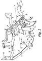
- a vehicle subframe comprises a rear part 10 and a front part 12.
- the rear part 10 comprises a pair of side sections 14, 16 extending approximately parallel to the longitudinal axis X-X of the vehicle, and a transverse cross beam 18 joined at its ends to the side sections 14, 16 approximately mid-way between their ends.
- Each side section 14, 16 is attached to the vehicle body at two points: a rear mounting 20 at its rear end 22 and a front mounting 24 at its front end 26.
- Each front mounting 24 comprises a mounting bracket 28 which has lower end 30 attached to the side section 14, 16 and its upper end 32 attached to the vehicle body.
- the rear part 10 of the subframe therefore forms a rigid H-shaped support, attached to the vehicle body at each corner, to which various components of the vehicle can be attached.
- a suspension arm 34 is mounted on each side section 14, 16 by means of a pair of bushes 36, 38.
- One of these 36 is approximately level with the rear edge 39 of the cross beam 18, and has a horizontal axis parallel to that of the cross beam 18, and the other 38 is approximately level with the front edge 40 of the cross beam 18 and has a vertical axis.
- the bushes 36, 38 define a pivot axis, extending substantially parallel to the side section 14, 16, about which the suspension arm 34 can pivot, allowing vertical movement of the wheel mounted on it.
- a steering rack 42 is also mounted on the cross beam 18, as is an anti-roll bar 44.
- the front part 12 of the subframe is formed from a piece of tubing 45 which is bent so as to form a front portion 46 arranged to extend across the vehicle and two side portions 48 extending rearwardly from the ends of the front portion.
- Each of the side portions 48 includes a first portion 50 extending outwards and rearwards from the end of the front portion 46 and a second portion 52 extending inwards and rearwards from the rear end of the first portion, which together form a crumple zone in the subframe, and a third portion 54 extending rearwardly, parallel to the longitudinal axis X - X of the vehicle, from the rear end of the second portion 52.
- the tube 45 ends in a straight joint portion 56, which is arranged to be a sliding fit into a joint portion 58 at the front end of the corresponding side section 14, 16 of the rear part 10 of the subframe, just forward of the mounting brackets 28.
- Aligned holes 60 through the joint portions 56, 58 allow the front and rear parts 10, 12 of the subframe to be releasably bolted together.
- a sheet metal front mounting bracket 62 is welded at its lower end onto the front part 12 of the subframe at each end of the front portion 46 where it joins the front end of the side portions 48. These brackets extend vertically upwards from the subframe and are attached at their upper ends to the front end of respective longitudinal structures 64 in the vehicle body.
- the longitudinal structures 64 each have a crumple zone 66 at the front end, the brackets 62 being attached to the front end of the crumple zones.
- the subframe front part 12 is situated below the longitudinal structures 64.
- a bumper armature 68 is also attached to the brackets 62 above the subframe front portion 46 and level with the longitudinal structures 64.
- the armature extends across the front of the vehicle substantially parallel to the subframe front portion 46 and above it, the front edges of the armature 68 and the subframe front portion being substantially level along the longitudinal axis of the vehicle.
- An outer bumper member 70 comprising an integral part of a body panel of the vehicle, is situated on front of the armature 68 and subframe front portion 46, covering them both but spaced slightly away from them.
- the front mounting points 24 of the rear part 10 of the subframe are attached to the longitudinal structures to the rear of the crumple zones 66.
- the load of the bumper assembly on the pedestrian and hence also the load of the pedestrian on the bumper assembly, provided that load is sufficient to deform the outer bumper panel 70, is spread between the armature 68 and the subframe front portion 46. This spreading of load can help to reduce injury to the pedestrian.
- the energy of the impact received both by the armature and the subframe front portion 46 is transmitted by the brackets 62 into the crumple zones 66 in the body and those 50, 52 in the subframe side portions 48 which can therefore crumple together to absorb the impact energy whilst being held in a parallel relationship to each other by the brackets 62. Because the subframe extends forwards to the front of the vehicle, level with the bumper armature and the front ends of the body longitudinal structures 64, it is effective in absorbing impact energy from almost the moment of impact.
- a second embodiment of the invention is similar to the first, with corresponding parts given the same reference numeral preceded by a 1.
- the difference with the second embodiment is that the front portion 46 of the subframe is omitted, and the front ends of the two side portions 148 are bolted onto the bottom ends of the front mounting brackets 162 on which the bumper armature 168 is mounted.
- the bumper armature therefore takes all of the load in a frontal impact, but this load is still reacted back through the subframe side portions 148 and the longitudinal body structures 164 in parallel.
- subframe side portions 148 and the longitudinal body structures 164 are substantially parallel to each other and the brackets 162 connect them both rigidly to the bumper armature 168, in the event of a frontal impact they deform by crumpling simultaneously whilst remaining substantially parallel with each other.
- the subframe therefore contributes significantly to the energy absorbing capability of the overall structure which is stiffer than if either the body structure 164 or the subframe 110 acted alone to absorb the energy.
Landscapes
- Engineering & Computer Science (AREA)
- Chemical & Material Sciences (AREA)
- Combustion & Propulsion (AREA)
- Transportation (AREA)
- Mechanical Engineering (AREA)
- Body Structure For Vehicles (AREA)
Claims (9)
- Fahrzeug mit einem Aufbau und einem daran angebrachten Hilfsrahmen (10, 12), der zum Tragen verschiedener Fahrzeugbauteile (34, 42, 44) angeordnet ist, wobei der Aufbau zwei sich im wesentlichen parallel zur Längsachse (X - X) des Fahrzeugs erstreckende Längsträger (64) enthält, deren Vorderenden mit einem aufprallabsorbierenden Querglied (68) verbunden sind,
dadurch gekennzeichnet, daß der Hilfsrahmen (10, 12) zwei Längsabschnitte (14, 16, 48) enthält, die sich im wesentlichen parallel zu den Längsträgern (64) und im wesentlichen genauso weit nach vorne erstrecken und deren Vorderenden mit einem aufprallabsorbierenden Querglied (68) verbunden sind, wobei Vorderteile (48) der Längshilfsrahmenabschnitte so angeordnet sind, daß sie sich bei einem Frontalzusammenstoß des Fahrzeugs vor Hinterteilen (14, 16) der Längshilfsrahmenabschnitte verformen, und wobei die Vorderteile (48) der Längshilfsrahmenabschnitte von den Hinterteilen (14, 16) der Längshilfsrahmenabschnitte lösbar sind, um einen Austausch der Vorderteile (48) zu ermöglichen. - Fahrzeug nach Anspruch 1,
bei dem die Längshilfsrahmenabschnitte (48) und die Längsträger (64) beide an ihren Vorderenden mit dem gleichen aufprallabsorbierenden Querglied (68) verbunden sind. - Fahrzeug nach Anspruch 2,
bei dem das aufprallabsorbierende Querglied (68) einen Stoßfängerträger umfaßt. - Fahrzeug nach Anspruch 2 oder 3,
bei dem das Vorderende jedes der Längsträger (64) mittels eines starren Halters (62) mit dem Vorderteil eines jeweiligen der Längshilfsrahmenabschnitte (48) verbunden ist und das aufprallabsorbierende Querglied (68) an den Haltern (62) befestigt ist. - Fahrzeug nach einem der vorhergehenden Ansprüche,
bei dem der Hilfsrahmen (10, 12) weiterhin einen Querträger (46) umfaßt, der das aufprallabsorbierende Querglied bildet, an dem die Vorderenden der Längshilfsrahmenabschnitte (48) befestigt sind. - Fahrzeug nach Anspruch 5, sofern von Anspruch 3 abhängig, bei dem sich der Querträger (46) im wesentlichen parallel zum Stoßfängerträger (68) erstreckt und in Längsrichtung des Fahrzeugs im wesentlichen auf gleicher Höhe damit positioniert ist.
- Fahrzeug nach einem der vorhergehenden Ansprüche,
bei dem der Hilfsrahmen (10, 12) am Aufbau (64) elastisch angebracht und so angeordnet ist, daß er den Aufbau von Vibrationen der Bauteile trennt. - Fahrzeug nach einem der vorhergehenden Ansprüche,
bei dem die Bauteile mindestens eine Lenkeinrichtung (42) und/oder einen Stabilisator (44) und/oder einen Aufhängungslenker (34) umfassen. - Fahrzeug nach einem der vorhergehenden Ansprüche,
bei dem der Hilfsrahmen (10, 12) unter den Längsträgern (64) angeordnet ist.
Applications Claiming Priority (4)
| Application Number | Priority Date | Filing Date | Title |
|---|---|---|---|
| GB9726825 | 1997-12-20 | ||
| GBGB9726823.9A GB9726823D0 (en) | 1997-12-20 | 1997-12-20 | Vehicle subframes |
| GBGB9726825.4A GB9726825D0 (en) | 1997-12-20 | 1997-12-20 | Vehicle bumper assemblies |
| GB9726823 | 1997-12-20 |
Publications (3)
| Publication Number | Publication Date |
|---|---|
| EP0926048A2 EP0926048A2 (de) | 1999-06-30 |
| EP0926048A3 EP0926048A3 (de) | 2001-03-28 |
| EP0926048B1 true EP0926048B1 (de) | 2002-07-10 |
Family
ID=26312807
Family Applications (1)
| Application Number | Title | Priority Date | Filing Date |
|---|---|---|---|
| EP98310222A Expired - Lifetime EP0926048B1 (de) | 1997-12-20 | 1998-12-14 | Hilfsrahmen für Fahrzeuge |
Country Status (5)
| Country | Link |
|---|---|
| US (1) | US6193274B1 (de) |
| EP (1) | EP0926048B1 (de) |
| DE (1) | DE69806460T2 (de) |
| ES (1) | ES2176916T3 (de) |
| GB (1) | GB2334008A (de) |
Cited By (1)
| Publication number | Priority date | Publication date | Assignee | Title |
|---|---|---|---|---|
| DE102018209115A1 (de) | 2018-06-08 | 2019-12-12 | Audi Ag | Hilfsrahmen für ein Kraftfahrzeug |
Families Citing this family (44)
| Publication number | Priority date | Publication date | Assignee | Title |
|---|---|---|---|---|
| DE19923693A1 (de) * | 1999-05-22 | 2000-11-23 | Volkswagen Ag | Vollhilfsrahmen |
| JP3446679B2 (ja) * | 1999-09-08 | 2003-09-16 | 日産自動車株式会社 | サイドメンバの中間ジョイント |
| SE516470C2 (sv) * | 1999-09-29 | 2002-01-15 | Scania Cv Ab | Framaxelanordning för ett tungt fordon |
| US6416119B1 (en) * | 1999-10-26 | 2002-07-09 | Daimlerchrysler | Vehicle front end construction through the use of hydroformed tubes |
| FR2800695B1 (fr) * | 1999-11-08 | 2001-12-07 | Renault | Vehicule, notamment de tourisme, a structure d'encaissement de choc anti-chevauchement |
| DE19959607A1 (de) * | 1999-12-10 | 2001-06-13 | Volkswagen Ag | Fahrzeugkarosserie mit einer bodenseitigen Verstrebungsanordnung |
| DE60123723T2 (de) * | 2000-09-19 | 2007-01-18 | Mazda Motor Corp. | Hilfsrahmen für Kraftfahrzeuge |
| DE10058113B4 (de) * | 2000-11-22 | 2016-07-21 | Volkswagen Ag | Hilfsrahmenmodul |
| JP3832233B2 (ja) * | 2000-12-05 | 2006-10-11 | スズキ株式会社 | 車両の前部車体構造 |
| US6945348B2 (en) * | 2001-07-25 | 2005-09-20 | Decoma International Inc. | Pedestrian safety system having lower leg impact |
| DE60207015T2 (de) * | 2001-07-31 | 2006-08-03 | Nissan Motor Co., Ltd., Yokohama | Vorbaustruktur für ein Kraftfahrzeug |
| KR100435681B1 (ko) * | 2001-09-11 | 2004-06-12 | 현대자동차주식회사 | 스티어링 기어 프레임을 이용한 최적의 서스펜션 레이아웃 |
| JP4576780B2 (ja) * | 2001-09-21 | 2010-11-10 | マツダ株式会社 | 車体のフレーム構造及び車体フレームの製造方法 |
| FR2832686B1 (fr) | 2001-11-26 | 2004-01-30 | Renault | Structure avant de vehicule automobile en berceau destinee a relier les longerons de la structure de caisse |
| DE10163220B4 (de) * | 2001-12-21 | 2012-08-02 | Volkswagen Ag | Kraftfahrzeugvorderwagen |
| FR2835799B1 (fr) * | 2002-02-08 | 2004-05-07 | Renault | Structure pour vehicule automobile et vehicule equipe d'une telle structure |
| JP4026815B2 (ja) * | 2002-09-06 | 2007-12-26 | 本田技研工業株式会社 | サブフレームの取り付け構造 |
| DE10321573B4 (de) * | 2003-05-14 | 2008-09-25 | Daimler Ag | Crashstruktur für eine Kraftwagen-Rohbaustruktur |
| GB0319493D0 (en) * | 2003-08-20 | 2003-09-17 | Ford Global Tech Llc | Motor vehicles |
| US6938948B1 (en) * | 2004-02-27 | 2005-09-06 | Daimlerchrysler Corporation | Energy absorbing front frame structure for a vehicle |
| US7213873B2 (en) | 2004-03-25 | 2007-05-08 | Mazda Motor Corporation | Vehicle front-part structure |
| FR2869583B1 (fr) * | 2004-04-29 | 2006-06-23 | Renault Sas | Structure avant de vehicule automobile et traverse de chocs pour cette structure |
| US20050248114A1 (en) * | 2004-05-10 | 2005-11-10 | Winkler Frank F | Vehicle sub-frame connection assembly |
| DE102004058380A1 (de) * | 2004-12-03 | 2006-06-14 | Audi Ag | Hilfsrahmen für ein Kraftfahrzeug |
| US7896428B2 (en) | 2005-01-28 | 2011-03-01 | Toyota Jidosha Kabushiki Kaisha | Vehicle body structure |
| FR2883830B1 (fr) * | 2005-03-30 | 2007-08-24 | Vallourec Vitry | Traverse de pare-chocs pour vehicules automobiles, preservant les pietons |
| US7287788B2 (en) * | 2005-06-08 | 2007-10-30 | Ford Global Technologies, Llc | Single component automotive bumper and lower frame rail |
| DE102006036852B4 (de) * | 2006-08-07 | 2018-11-08 | GM Global Technology Operations LLC (n. d. Ges. d. Staates Delaware) | Frontpartie für ein Kraftfahrzeug |
| DE602006011484D1 (de) * | 2006-12-01 | 2010-02-11 | Ford Global Tech Llc | Fahrzeugstossfänger und untere Längsträger |
| WO2009014526A1 (en) * | 2007-07-24 | 2009-01-29 | Mack Trucks, Inc. | Front bumper arrangement for a truck for single or dual tow points |
| JP5573413B2 (ja) * | 2010-06-28 | 2014-08-20 | マツダ株式会社 | 車両の下部車体構造 |
| DE102010034759B4 (de) * | 2010-08-19 | 2014-12-18 | Audi Ag | Anordnung zum Schutz eines Betriebsmittelbehälters in einem Kraftfahrzeug |
| DE102011075339A1 (de) * | 2011-05-05 | 2012-11-08 | Bayerische Motoren Werke Aktiengesellschaft | Fahrschemel |
| DE102011102116A1 (de) * | 2011-05-20 | 2012-11-22 | GM Global Technology Operations LLC (n. d. Gesetzen des Staates Delaware) | Crashstruktur zur Anbindung an einen Vorderhilfsrahmen für ein Kraftfahrzeug |
| DE102011122556B3 (de) * | 2011-09-22 | 2012-11-22 | Benteler Automobiltechnik Gmbh | Achsanordnung mit Ausklinkvorrichtung |
| BR112014031099A2 (pt) * | 2012-06-15 | 2017-06-27 | Honda Motor Co Ltd | estrutura de parte posterior de corpo de veículo |
| US8550545B1 (en) | 2012-08-20 | 2013-10-08 | Ford Global Technologies, Llc | Truck front-end support frame |
| US8876132B2 (en) * | 2012-09-28 | 2014-11-04 | Ford Global Technologies, Llc | Front end assembly for vehicle chassis |
| JP2014094588A (ja) * | 2012-11-07 | 2014-05-22 | Toyota Motor Corp | 車体前部構造 |
| TWM470790U (zh) * | 2013-09-05 | 2014-01-21 | Kuianda Company Ltd | 組合式電動代步車車架結構 |
| DE102013021344A1 (de) * | 2013-12-14 | 2015-06-18 | Audi Ag | Anbindung eines Frontends eines Kraftfahrzeugs an einen Hilfsrahmen des Kraftfahrzeugs |
| CN106005034B (zh) * | 2016-06-22 | 2017-05-03 | 黄河交通学院 | 一种轻量化汽车前车架及制备前车架的铝合金的制备工艺 |
| US10106197B2 (en) * | 2017-03-07 | 2018-10-23 | Ford Global Technologies, Llc | Device and assembly for protecting a front end module of a motor vehicle |
| US10633028B2 (en) * | 2017-11-22 | 2020-04-28 | Honda Motor Co., Ltd. | Autonomous all-terrain vehicle frame structure |
Family Cites Families (23)
| Publication number | Priority date | Publication date | Assignee | Title |
|---|---|---|---|---|
| US3520552A (en) * | 1968-02-21 | 1970-07-14 | Ford Motor Co | Frame structure for a motor vehicle |
| US3718364A (en) * | 1971-10-26 | 1973-02-27 | Gen Motors Corp | Vehicle body and frame construction |
| GB1419698A (de) * | 1972-04-19 | 1976-01-07 | ||
| DE2239485A1 (de) * | 1972-08-11 | 1975-02-27 | Opel Adam Ag | Energieabsorber, insbesondere zur verwendung in fahrzeugen, insbesondere kraftfahrzeugen |
| JPS49128415A (de) * | 1973-04-16 | 1974-12-09 | ||
| US3819224A (en) * | 1973-05-10 | 1974-06-25 | Gen Motors Corp | Vehicle body construction |
| DE2636655A1 (de) * | 1976-08-14 | 1978-02-16 | Daimler Benz Ag | Hohltraeger fuer fahrzeuge und verfahren zu seiner herstellung |
| DE2918136C2 (de) | 1979-05-05 | 1981-06-04 | Volkswagenwerk Ag, 3180 Wolfsburg | Vorderwagen für ein Frontlenkerfahrzeug |
| GB2055704A (en) | 1979-08-03 | 1981-03-11 | Dow D | Electric motor vehicle |
| SE432395B (sv) * | 1980-11-24 | 1984-04-02 | Saab Scania Ab | Frontparti i motorfordon |
| DE3223156A1 (de) | 1982-06-22 | 1983-12-22 | Dr.Ing.H.C. F. Porsche Ag, 7000 Stuttgart | Aufbau fuer kraftfahrzeuge, insbesondere personenkraftwagen |
| DE3522447C2 (de) | 1985-01-24 | 1995-01-05 | Volkswagen Ag | Vorderwagen für ein Kraftfahrzeug |
| DE3603706A1 (de) | 1986-02-06 | 1987-08-13 | Audi Ag | Rahmenanordnung eines vorzugsweise mit einem selbsttragenden wagenkasten versehenen personenkraftwagens |
| DE3925990A1 (de) | 1989-08-05 | 1991-02-07 | Daimler Benz Ag | Baugruppe fuer den front- und heckbereich eines kraftfahrzeugs |
| US5372216A (en) * | 1990-10-08 | 1994-12-13 | Mazda Motor Corporation | Power plant supporting structure of automotive vehicle |
| US5358300A (en) * | 1993-10-25 | 1994-10-25 | Davidson Textron Inc. | Modular assembly for vehicle body |
| IT1273160B (it) * | 1994-04-27 | 1997-07-07 | Fiat Auto Spa | Struttura di autoveicolo e procedimento di assemblaggio di un autoveicolo avente una siffatta struttura |
| JPH08164869A (ja) | 1994-12-15 | 1996-06-25 | Fuji Heavy Ind Ltd | 車両の前部フレーム構造 |
| US5862877A (en) * | 1994-12-20 | 1999-01-26 | Cosma International Inc. | Cradle assembly |
| JP3351233B2 (ja) * | 1995-12-27 | 2002-11-25 | トヨタ自動車株式会社 | パワートレインの支持装置 |
| DE19611934C1 (de) | 1996-03-27 | 1997-04-17 | Ymos Ag Ind Produkte | Frontmodul für Kraftfahrzeuge |
| ZA973413B (en) | 1996-04-30 | 1998-10-21 | Autokinetics Inc | Modular vehicle frame |
| US5853195A (en) * | 1997-01-16 | 1998-12-29 | Ford Global Technologies, Inc. | Front rail assembly for a vehicle |
-
1998
- 1998-12-11 GB GB9827351A patent/GB2334008A/en not_active Withdrawn
- 1998-12-14 ES ES98310222T patent/ES2176916T3/es not_active Expired - Lifetime
- 1998-12-14 EP EP98310222A patent/EP0926048B1/de not_active Expired - Lifetime
- 1998-12-14 DE DE69806460T patent/DE69806460T2/de not_active Expired - Lifetime
- 1998-12-15 US US09/211,564 patent/US6193274B1/en not_active Expired - Lifetime
Cited By (2)
| Publication number | Priority date | Publication date | Assignee | Title |
|---|---|---|---|---|
| DE102018209115A1 (de) | 2018-06-08 | 2019-12-12 | Audi Ag | Hilfsrahmen für ein Kraftfahrzeug |
| DE102018209115B4 (de) | 2018-06-08 | 2023-02-23 | Audi Ag | Hilfsrahmen für ein Kraftfahrzeug |
Also Published As
| Publication number | Publication date |
|---|---|
| GB2334008A (en) | 1999-08-11 |
| ES2176916T3 (es) | 2002-12-01 |
| EP0926048A2 (de) | 1999-06-30 |
| US6193274B1 (en) | 2001-02-27 |
| GB9827351D0 (en) | 1999-02-03 |
| DE69806460D1 (de) | 2002-08-14 |
| EP0926048A3 (de) | 2001-03-28 |
| DE69806460T2 (de) | 2003-01-16 |
Similar Documents
| Publication | Publication Date | Title |
|---|---|---|
| EP0926048B1 (de) | Hilfsrahmen für Fahrzeuge | |
| EP0477654B1 (de) | Vorderwagenaufbau für ein Kraftfahrzeug | |
| US6109629A (en) | Subframe for motor vehicles | |
| US5611569A (en) | Vehicle subframe assembly | |
| US20060001228A1 (en) | Vehicle end structure | |
| JP3531767B2 (ja) | 車両用バンパ取付構造 | |
| CN110949516B (zh) | 车体前部结构 | |
| JPH08268322A (ja) | 車 体 | |
| JP3606252B2 (ja) | 車体前部構造 | |
| US6520565B1 (en) | Arrangement which makes it possible to displace a cab of a vehicle | |
| CN111806561A (zh) | 车辆的前支撑 | |
| US6095592A (en) | Construction of root portion of front side member | |
| JPH10226363A (ja) | 自動車のサイドストラクチャ構造 | |
| CN210258578U (zh) | 前车体加强结构 | |
| JPH058755A (ja) | 自動車の前部構造 | |
| JP3622715B2 (ja) | 車体前部構造 | |
| JP2004276735A (ja) | フロントサブフレーム構造 | |
| JPH04300792A (ja) | 自動車の下部車体構造 | |
| GB2332883A (en) | Energy absorbing vehicle subframe | |
| JPH0747844A (ja) | 自動車のパワートレイン支持構造 | |
| JP2004114814A (ja) | 車体前部構造 | |
| KR20190040793A (ko) | 전방 차체 보강구조 | |
| KR100333881B1 (ko) | 자동차 프레임 보강 구조 | |
| JP2516208B2 (ja) | 自動車の前部車体構造 | |
| EP0918681B1 (de) | Konsole für eine strebe an einem fahrzeug |
Legal Events
| Date | Code | Title | Description |
|---|---|---|---|
| PUAI | Public reference made under article 153(3) epc to a published international application that has entered the european phase |
Free format text: ORIGINAL CODE: 0009012 |
|
| AK | Designated contracting states |
Kind code of ref document: A2 Designated state(s): DE ES FR GB IT SE |
|
| AX | Request for extension of the european patent |
Free format text: AL;LT;LV;MK;RO;SI |
|
| RAP1 | Party data changed (applicant data changed or rights of an application transferred) |
Owner name: BAYERISCHE MOTOREN WERKE AKTIENGESELLSCHAFT |
|
| PUAL | Search report despatched |
Free format text: ORIGINAL CODE: 0009013 |
|
| AK | Designated contracting states |
Kind code of ref document: A3 Designated state(s): AT BE CH CY DE DK ES FI FR GB GR IE IT LI LU MC NL PT SE |
|
| AX | Request for extension of the european patent |
Free format text: AL;LT;LV;MK;RO;SI |
|
| 17P | Request for examination filed |
Effective date: 20010602 |
|
| GRAG | Despatch of communication of intention to grant |
Free format text: ORIGINAL CODE: EPIDOS AGRA |
|
| 17Q | First examination report despatched |
Effective date: 20011004 |
|
| AKX | Designation fees paid |
Free format text: DE ES FR GB IT SE |
|
| GRAG | Despatch of communication of intention to grant |
Free format text: ORIGINAL CODE: EPIDOS AGRA |
|
| GRAH | Despatch of communication of intention to grant a patent |
Free format text: ORIGINAL CODE: EPIDOS IGRA |
|
| GRAH | Despatch of communication of intention to grant a patent |
Free format text: ORIGINAL CODE: EPIDOS IGRA |
|
| GRAA | (expected) grant |
Free format text: ORIGINAL CODE: 0009210 |
|
| AK | Designated contracting states |
Kind code of ref document: B1 Designated state(s): DE ES FR GB IT SE |
|
| REG | Reference to a national code |
Ref country code: GB Ref legal event code: FG4D |
|
| REF | Corresponds to: |
Ref document number: 69806460 Country of ref document: DE Date of ref document: 20020814 |
|
| ET | Fr: translation filed | ||
| REG | Reference to a national code |
Ref country code: ES Ref legal event code: FG2A Ref document number: 2176916 Country of ref document: ES Kind code of ref document: T3 |
|
| PLBE | No opposition filed within time limit |
Free format text: ORIGINAL CODE: 0009261 |
|
| STAA | Information on the status of an ep patent application or granted ep patent |
Free format text: STATUS: NO OPPOSITION FILED WITHIN TIME LIMIT |
|
| 26N | No opposition filed |
Effective date: 20030411 |
|
| REG | Reference to a national code |
Ref country code: FR Ref legal event code: PLFP Year of fee payment: 18 |
|
| PGFP | Annual fee paid to national office [announced via postgrant information from national office to epo] |
Ref country code: GB Payment date: 20151217 Year of fee payment: 18 |
|
| PGFP | Annual fee paid to national office [announced via postgrant information from national office to epo] |
Ref country code: ES Payment date: 20151120 Year of fee payment: 18 Ref country code: SE Payment date: 20151211 Year of fee payment: 18 |
|
| PGFP | Annual fee paid to national office [announced via postgrant information from national office to epo] |
Ref country code: IT Payment date: 20151229 Year of fee payment: 18 |
|
| REG | Reference to a national code |
Ref country code: FR Ref legal event code: PLFP Year of fee payment: 19 |
|
| REG | Reference to a national code |
Ref country code: SE Ref legal event code: EUG |
|
| GBPC | Gb: european patent ceased through non-payment of renewal fee |
Effective date: 20161214 |
|
| PG25 | Lapsed in a contracting state [announced via postgrant information from national office to epo] |
Ref country code: SE Free format text: LAPSE BECAUSE OF NON-PAYMENT OF DUE FEES Effective date: 20161215 |
|
| PG25 | Lapsed in a contracting state [announced via postgrant information from national office to epo] |
Ref country code: IT Free format text: LAPSE BECAUSE OF NON-PAYMENT OF DUE FEES Effective date: 20161214 |
|
| PG25 | Lapsed in a contracting state [announced via postgrant information from national office to epo] |
Ref country code: GB Free format text: LAPSE BECAUSE OF NON-PAYMENT OF DUE FEES Effective date: 20161214 |
|
| REG | Reference to a national code |
Ref country code: FR Ref legal event code: PLFP Year of fee payment: 20 |
|
| PGFP | Annual fee paid to national office [announced via postgrant information from national office to epo] |
Ref country code: FR Payment date: 20171219 Year of fee payment: 20 Ref country code: DE Payment date: 20171212 Year of fee payment: 20 |
|
| PG25 | Lapsed in a contracting state [announced via postgrant information from national office to epo] |
Ref country code: ES Free format text: LAPSE BECAUSE OF FAILURE TO SUBMIT A TRANSLATION OF THE DESCRIPTION OR TO PAY THE FEE WITHIN THE PRESCRIBED TIME-LIMIT Effective date: 20020710 |
|
| REG | Reference to a national code |
Ref country code: ES Ref legal event code: FD2A Effective date: 20181113 |
|
| REG | Reference to a national code |
Ref country code: DE Ref legal event code: R071 Ref document number: 69806460 Country of ref document: DE |
|
| PG25 | Lapsed in a contracting state [announced via postgrant information from national office to epo] |
Ref country code: ES Free format text: LAPSE BECAUSE OF FAILURE TO SUBMIT A TRANSLATION OF THE DESCRIPTION OR TO PAY THE FEE WITHIN THE PRESCRIBED TIME-LIMIT Effective date: 20161215 |