EP0924849B1 - Motor control apparatus - Google Patents
Motor control apparatus Download PDFInfo
- Publication number
- EP0924849B1 EP0924849B1 EP98310365A EP98310365A EP0924849B1 EP 0924849 B1 EP0924849 B1 EP 0924849B1 EP 98310365 A EP98310365 A EP 98310365A EP 98310365 A EP98310365 A EP 98310365A EP 0924849 B1 EP0924849 B1 EP 0924849B1
- Authority
- EP
- European Patent Office
- Prior art keywords
- speed
- motors
- speeds
- motor
- target
- Prior art date
- Legal status (The legal status is an assumption and is not a legal conclusion. Google has not performed a legal analysis and makes no representation as to the accuracy of the status listed.)
- Expired - Lifetime
Links
- 238000000034 method Methods 0.000 claims description 16
- 230000008859 change Effects 0.000 claims description 6
- 238000001514 detection method Methods 0.000 claims description 5
- 230000002093 peripheral effect Effects 0.000 claims description 4
- 230000004044 response Effects 0.000 claims description 4
- 230000015572 biosynthetic process Effects 0.000 claims description 2
- 230000000737 periodic effect Effects 0.000 claims description 2
- 238000004590 computer program Methods 0.000 claims 1
- 230000015654 memory Effects 0.000 description 3
- 230000008569 process Effects 0.000 description 3
- 238000006243 chemical reaction Methods 0.000 description 2
- 238000010586 diagram Methods 0.000 description 2
- 229910052736 halogen Inorganic materials 0.000 description 2
- 150000002367 halogens Chemical class 0.000 description 2
- 239000007787 solid Substances 0.000 description 2
- 230000001360 synchronised effect Effects 0.000 description 2
- 230000007704 transition Effects 0.000 description 2
- 239000000969 carrier Substances 0.000 description 1
- 230000003247 decreasing effect Effects 0.000 description 1
- 239000011521 glass Substances 0.000 description 1
- 230000007246 mechanism Effects 0.000 description 1
- 230000002194 synthesizing effect Effects 0.000 description 1
Images

Classifications
-
- H—ELECTRICITY
- H02—GENERATION; CONVERSION OR DISTRIBUTION OF ELECTRIC POWER
- H02P—CONTROL OR REGULATION OF ELECTRIC MOTORS, ELECTRIC GENERATORS OR DYNAMO-ELECTRIC CONVERTERS; CONTROLLING TRANSFORMERS, REACTORS OR CHOKE COILS
- H02P5/00—Arrangements specially adapted for regulating or controlling the speed or torque of two or more electric motors
- H02P5/46—Arrangements specially adapted for regulating or controlling the speed or torque of two or more electric motors for speed regulation of two or more dynamo-electric motors in relation to one another
- H02P5/50—Arrangements specially adapted for regulating or controlling the speed or torque of two or more electric motors for speed regulation of two or more dynamo-electric motors in relation to one another by comparing electrical values representing the speeds
-
- H—ELECTRICITY
- H02—GENERATION; CONVERSION OR DISTRIBUTION OF ELECTRIC POWER
- H02N—ELECTRIC MACHINES NOT OTHERWISE PROVIDED FOR
- H02N2/00—Electric machines in general using piezoelectric effect, electrostriction or magnetostriction
- H02N2/10—Electric machines in general using piezoelectric effect, electrostriction or magnetostriction producing rotary motion, e.g. rotary motors
- H02N2/14—Drive circuits; Control arrangements or methods
- H02N2/142—Small signal circuits; Means for controlling position or derived quantities, e.g. speed, torque, starting, stopping, reversing
-
- H—ELECTRICITY
- H02—GENERATION; CONVERSION OR DISTRIBUTION OF ELECTRIC POWER
- H02P—CONTROL OR REGULATION OF ELECTRIC MOTORS, ELECTRIC GENERATORS OR DYNAMO-ELECTRIC CONVERTERS; CONTROLLING TRANSFORMERS, REACTORS OR CHOKE COILS
- H02P1/00—Arrangements for starting electric motors or dynamo-electric converters
- H02P1/16—Arrangements for starting electric motors or dynamo-electric converters for starting dynamo-electric motors or dynamo-electric converters
- H02P1/54—Arrangements for starting electric motors or dynamo-electric converters for starting dynamo-electric motors or dynamo-electric converters for starting two or more dynamo-electric motors
- H02P1/56—Arrangements for starting electric motors or dynamo-electric converters for starting dynamo-electric motors or dynamo-electric converters for starting two or more dynamo-electric motors simultaneously
Definitions
- the present invention relates to a motor-control method and motor control apparatus for controlling a plurality of motors.
- a preferred embodiment relates to a motor control apparatus in combination with an image forming apparatus.
- a conventional motor control apparatus which is required to synchronously rotate and stop a plurality of motors, normally uses motors which are controlled by an identical control method and have relatively small variations in rotation characteristics due to their individual differences, for example, pulse motors, DC motors, and the like.
- a motor for driving a photosensitive element as an image carrier and a motor for driving a convey means for conveying a transfer element such as a recording sheet or the like to the transfer position of the photosensitive element must be synchronously rotated not only during transfer for transferring a toner image on the photosensitive element onto the transfer element but also at the beginning or end (stop) of rotation of the photosensitive element.
- motors which are controlled by an identical control method and have relatively small variations in rotation characteristics due to their individual differences, are used, synchronous control of these motors is relatively easy.
- a motor with high rotation precision is required to drive the photosensitive element or transfer element so as to form a high-resolution image.
- the following technique has been proposed.
- a vibration wave motor that is a vibration type motor is used as one of the motors for driving the photosensitive element or transfer element together with other motors controlled by a different control method.
- a vibration type motor excites a plurality of vibrations at frequencies beyond the audible range in a vibration member, and obtains a driving force by synthesizing these vibrations.
- the vibration type motor realizes stable rotation at a constant speed, as described in detail in Japanese Patent Application Laid-Open Nos. 63-1379, 60-176470, 59-204477, and the like.
- the vibration type motor suffers variations in rotation characteristics due to individual differences of motors, and the driving frequency and voltage and the pulse width of the driving voltage must be periodically adjusted in correspondence with a signal output from a speed detection means such as an encoder signal so as to maintain stable rotation.
- the time for start up operation commonly varies due to variations of the motors, as shown in Fig. 10.
- the times required for the motor to reach a target speed have a time difference T2 - T1 between two motors, and the difference in total moving amount corresponds to the area bounded by the solid curve and one-dashed chain curve.
- the speed difference between the motors increases upon start up unless the start up operations of the motors are controlled, and may promote wears of the elements to be driven.
- US-A-4562388 discloses controlling a plurality of motors to change speed by causing each motor to increase speed by a predetermined amount in response to a timing signal applied to the individual speed controls of each motor.
- One concern of the application is to provide a motor control apparatus which can control the speeds of a plurality of motors with nearly no relative speed variations until they reach a final target speed.
- Another concern of the application is to provide an image forming apparatus, which can control the speeds of photosensitive drums as a plurality of image carriers, and the speed of transfer element convey means for conveying a transfer element to a transfer position of each photosensitive drum with nearly no relative speed variations until they reach a final target speed.
- One aspect of the application provides a control apparatus as defined in claim 1.
- a further aspect of the invention provides a method for controlling speed change in motors, as defined in claim 11.
- Figs. 1 and 2 show the first embodiment of the present invention.
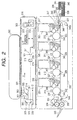
- Fig. 2 shows the schematic arrangement of the overall color image forming apparatus, and the arrangement of a color reader unit will be explained first.
- the color reader unit comprises a CCD 101, a circuit board 311 on which the CCD 101 is mounted, a printer processor 312, an original table glass (platen) 301, a document feeder 302 (a mirror surface pressing plate (not shown) may be attached in place of the document feeder 302), light sources 303 and 304 such as halogen lamps, fluorescent lamps, or the like for illuminating an original, reflectors 305 and 306 for focusing light beams emitted by the light sources 303 and 304 onto an original, mirrors 307 to 309, a lens 310 for focusing light reflected or projected by an original onto the CCD 101, a carriage 314 which carries the halogen lamps 303 and 304, reflectors 305 and 306, and mirror 307, a carriage 315 which carries the mirrors 308 and 309, and an interface (I/F) 313 with another IPU, and the like. Note that the carriages 314 and 315 mechanically move in a direction perpendicular to the electric scanning (main
- the printer unit is comprised of a magenta (M) image forming module 317, a cyan (C) image forming module 318, a yellow (Y) image forming module 319, and a black (K) image forming module 320. Since these image forming modules have the same arrangement, the M image forming module 317 will be described in detail below, and a detailed description of other image forming modules will be omitted.
- M magenta
- C cyan
- Y yellow
- K black
- the M image forming module 317 comprises a photosensitive drum 342 on the surface of which a latent image is formed by light coming from an LED array 210.
- a primary charging device 321 charges the surface of the photosensitive drum 342 to a predetermined potential to prepare for latent image formation.
- a developing device 322 develops a latent image formed on the surface of the photosensitive drum 342 to form a toner image. Note that the developing device 322 includes a sleeve 345 for applying a developing bias upon development.
- a transfer charging device 323 discharges from the back surface of a transfer element conveyor belt 333 to transfer a toner image on the surface of the photosensitive drum 342 onto a recording sheet or the like on the transfer element conveyor belt 333.
- This embodiment has no cleaner due to high transfer efficiency. However, a cleaner may be mounted.
- Transfer elements such as recording sheets or the like stored in a cassette 340 or 341 are picked up one by one by a pickup roller 339 or 338, and the picked-up transfer element is fed onto the transfer element conveyor belt 333 via paper feed rollers 336 and 337.
- the fed recording sheet is charged by an attraction charging device 346.
- a transfer element conveyor belt roller 348 drives the transfer element conveyor belt 333 and charges a recording sheet or the like together with the attraction charging device 346 to make the transfer element conveyor belt 333 attract the recording sheet or the like.
- the transfer element conveyor belt roller 348 may serve as a driving roller for driving the transfer element conveyor belt 333, or a driving roller for driving the transfer element conveyor belt 333 may be placed on the opposite side. Also, a driving roller 348a may be located in the vicinity of the roller 348.
- a sheet leading end sensor 347 detects the leading end of a recording sheet or the like on the transfer element conveyor belt 333. Note that the detection signal output from the sheet leading end sensor 347 is sent from the printer unit to the color reader unit, and is used as a sub-scanning synchronization signal upon sending a video signal from the color reader unit to the printer unit.
- the recording sheet or the like is then conveyed by the transfer element conveyor belt 333, and toner images are formed on its surface in the order of M, C, Y, and K in the image forming modules 317 to 320.
- the transfer element such as a recording sheet or the like that has left the K image forming module 320 is subjected to charge removal in a charge removing device 349 so as to easily peel off from the transfer element conveyor belt 333, and is then peeled from the transfer element conveyor belt 333.
- a peeling charging device 350 prevents image disturbance by peeling charge removal upon peeling the recording sheet or the like from the transfer element conveyor belt 333.
- the peeled recording sheet or the like is charged by pre-fixing charging devices 351 and 352 to compensate the toner attraction force and to prevent image disturbance, and is then supplied to a fixing device 334 to thermally fix the toner images formed thereon.
- the recording sheet or the like is then exhausted onto an exhaust tray 335.
- this embodiment uses vibration type motors as driving motors for rotating the photosensitive drums 342 to 345, and also uses a vibration type motor as a driving motor for rotating the driving roller for driving the transfer element conveyor belt 333.
- the vibration type motor exploits a plurality of vibrations excited in a vibration member at frequencies normally in the ultrasonic range (i.e., vibration member is vibrated by applying a periodic signal to an electro-mechanical energy conversion element on the vibration member in which the electro-mechanical energy conversion element such as a piezoelectric member or the like is located on an elastic member so as to obtain a driving force).
- the driving frequency and driving voltage, and the pulse width of the driving voltage are controlled in accordance with a speed detection signal which is detected by a speed sensor for detecting the driving speed of each motor and is used for stably rotating the motor at a constant speed.
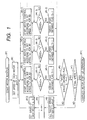
- Fig. 1 shows the control flow of the vibration type motors.
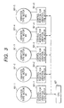
- Fig. 3 shows the control blocks-of the vibration type motors in this embodiment, and
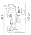
- Fig. 4 shows a control portion for one vibration type motor.
- vibration type motors 601-1 to 601-4 (M1 to M4) are used to drive the photosensitive drums, and a vibration type motor (M5) 601-5 is used to drive the transfer element conveyor belt.
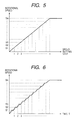
- the start up process from the beginning of the start up operation until a steady speed (final target speed) is reached is divided into n steps (n is an integer within the range n ⁇ 2), and Sn represents the divided target speed (prescribed speed value), as shown in Fig. 5.
- Fig. 4 shows a control portion 600 for each vibration type motor.
- a target rotational speed is set in memory a of a target speed setting portion 605 by an externally set target speed 608.
- a speed control circuit 604 issues commands to a pulse width setting circuit 602 and frequency setting circuit 603 on the basis of speed information from the target speed setting portion 605 and a signal output from an encoder 606 attached onto the shaft of the vibration type motor 601.
- the pulse width setting circuit 602 generates pulses for controlling the vibration type motor 601 on the basis of the command from the speed control circuit 602 and information from the frequency setting circuit 603 so as to control the rotational speed of the vibration type motor.
- the speed control circuit 604 When the rotation locks at the target speed, the speed control circuit 604 outputs a speed lock signal to a CPU 607 for controlling all the vibration type motors, and the CPU 607 checks if the rotation has locked at the target speed. Note that the control portion 600 mentioned above is provided for each of the motors, as shown in Fig. 3 (501-1 to 501-5).
- Fig. 1 is a flow chart showing the start up operation of all the vibration type motors (M1 to M5) by the CPU 607.
- the rotational speeds of the motors are controlled to set equal peripheral speeds of the four photosensitive drums since these photosensitive drums have equal outer diameters.
- the speed control of the motor for driving the transfer element conveyor belt is to make the peripheral speed of the transfer element conveyor belt 333 equal to that of each photosensitive drum.
- a motor rotation start request is issued (#1)
- the CPU 607 sets speeds in the control portions 501-1 to 501-5 for vibration type motors shown in Fig. 3 (#2).
- the speeds set in step #2 are stored in the corresponding memories a, and each control portion for vibration type motor makes speed control in accordance with the value stored in its memory a.
- the first target speed S1 is supplied to each motor.
- the control portions for vibration type motors then start the start up processing of the corresponding vibration type motors.
- the rotational speed is controlled in accordance with a signal output from the encoder 606 attached to the vibration type motor while gradually decreasing frequency from a predetermined frequency, and the driving frequency and driving pulses are controlled to attain a prescribed speed Sn.
- the speed control circuit 604 outputs a speed lock signal, and the CPU 607 can detect based on this signal that the speed of that motor has reached the predetermined one.
- Speed control is executed so that each motor reaches its setting speed a as the divided target speed (#3-1, #3-2, #3-3, ...), and it is checked if the speed of each motor has reached the setting speed (#4-1, #4-2, #4-3, ). If the speed of each motor has reached the setting speed, speed obtained flags f1, f2, f3, ..., fn of the individual motors are set at 1 to indicate that the setting speed has been reached (#5-1, #5-2, #5-3, ...), and the flow then advances to step #6.
- step #6 It is checked in step #6 if all the speed obtained flags f1 to f5 are 1. If NO in step #6, the flow returns to steps #4-1, ... to repeat the aforementioned operations until all the speed obtained flags become 1.
- step #7 If all the speed obtained flags are 1, since all the motors are rotation-controlled at the same divided target speed, it is checked in step #7 if the current target speed is the final speed.
- step #7 If it is determined in step #7 that the current target speed is not the final speed, all the speed obtained flags are set at 0 to execute speed control at the next divided target speed (#8).
- the flow then advances to steps #3-1, #3-2, #3-3, ... to repeat the same operations.
- step #7 if it is determined in step #7 that the current target speed is the final speed, the flow advances to step #11 to complete the motor start up operation.
- the transfer element conveyor belt 333 is separated from each photosensitive drum.
- the motor speeds change, as shown in Fig. 6.
- the one-dashed chain curve in Fig. 6 indicates the speed characteristics of a vibration type motor with the lowest response speed, and the solid curve indicates those with higher response speed.
- the speed difference can be minimized compared to the conventional speed control shown in Fig. 10.
- all the motors to be controlled are vibration type motors.
- vibration type motors and DC motors are used together, the motor speeds change, as shown in Fig. 6, as in the first embodiment.
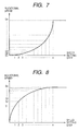
- the motor start up curve changes linearly, but may change nonlinearly, as shown in Figs. 7, 8, and 9. That is, vibration type motors have different start up characteristics depending on their sizes and control methods. For this reason, when the start up characteristics are changed in correspondence with characteristics to minimize speed differences in the start up characteristics of a plurality of motors, speed control can be easily attained.
- divided target speeds at lower speeds are set finely for a motor with poor start up characteristics at lower speeds.
- divided target speeds at higher speeds are set finely for a motor with poor start up characteristics at higher speeds.
- divided target speeds at lower and higher speeds are set finely for a motor with poor start up characteristics at both the lower and higher speeds.
- the driving speed of each motor and that of the element to be driven are in the ratio of 1 : 1.
- the setting speed changes in correspondence with the variable speed ratio of each element to be driven to minimize any speed differences of the element to be driven.
- a common setting speed value is set in each motor. If the drums have different outer diameters, their peripheral speeds are different even when the motors rotate at an equal speed. For this reason, the target speed is set in units of motors.
- the above embodiment has exemplified speed control upon starting up five motors.
- the present invention can also be applied to a case wherein a steady speed (final target speed) is changed like in a case wherein the image forming process speed in the image forming apparatus is changed.
- DC motors and vibration type motors may be controlled together.
- the speed setting range Sn up to the final speed is divided into n steps (n ⁇ 2) upon executing speed control of vibration type motors, DC motors, or AC motors
- the range between the lowest speed S1 and final speed Sn is divided into n steps with reference to the lowest speed that assures stable rotation of all the motors, and the next speed setting value is supplied to the motors after all the motors have reached the speed setting value.
- the motor start up operations that can assure start up characteristics at the lowest speed with low cost and can minimize speed differences can be realized. Since speed differences among motors upon motor start up are minimized, wears of elements to be driven produced by speed differences can be reduced.
Landscapes
- Engineering & Computer Science (AREA)
- Power Engineering (AREA)
- General Electrical Machinery Utilizing Piezoelectricity, Electrostriction Or Magnetostriction (AREA)
- Control Or Security For Electrophotography (AREA)
- Control Of Multiple Motors (AREA)
- Color Electrophotography (AREA)
Applications Claiming Priority (2)
| Application Number | Priority Date | Filing Date | Title |
|---|---|---|---|
| JP35354297 | 1997-12-22 | ||
| JP9353542A JPH11187688A (ja) | 1997-12-22 | 1997-12-22 | モータ制御方法、モータ制御装置および画像形成装置 |
Publications (3)
| Publication Number | Publication Date |
|---|---|
| EP0924849A2 EP0924849A2 (en) | 1999-06-23 |
| EP0924849A3 EP0924849A3 (en) | 2000-04-05 |
| EP0924849B1 true EP0924849B1 (en) | 2005-06-15 |
Family
ID=18431548
Family Applications (1)
| Application Number | Title | Priority Date | Filing Date |
|---|---|---|---|
| EP98310365A Expired - Lifetime EP0924849B1 (en) | 1997-12-22 | 1998-12-17 | Motor control apparatus |
Country Status (6)
| Country | Link |
|---|---|
| US (1) | US6114818A (enExample) |
| EP (1) | EP0924849B1 (enExample) |
| JP (1) | JPH11187688A (enExample) |
| KR (1) | KR100294159B1 (enExample) |
| CN (1) | CN1080023C (enExample) |
| DE (1) | DE69830559T2 (enExample) |
Families Citing this family (17)
| Publication number | Priority date | Publication date | Assignee | Title |
|---|---|---|---|---|
| JP2000050659A (ja) * | 1998-07-30 | 2000-02-18 | Canon Inc | 振動波モータの駆動制御装置、振動波モータを備えた装置、及び画像形成装置 |
| JP4544489B2 (ja) * | 1998-12-28 | 2010-09-15 | キヤノン株式会社 | 画像形成装置 |
| JP2001194958A (ja) * | 2000-01-11 | 2001-07-19 | Canon Inc | 画像形成装置 |
| GB0416888D0 (en) | 2004-07-29 | 2004-09-01 | Rolls Royce Plc | Controlling a plurality of devices |
| US7187142B2 (en) * | 2005-05-25 | 2007-03-06 | Rockwell Automation Technologies, Inc. | Motor drive with velocity noise filter |
| US7109670B1 (en) * | 2005-05-25 | 2006-09-19 | Rockwell Automation Technologies, Inc. | Motor drive with velocity-second compensation |
| JP2007011611A (ja) * | 2005-06-29 | 2007-01-18 | Ricoh Co Ltd | 位置決め制御装置、位置決め制御方法、その方法をコンピュータに実行させるプログラム、画像形成装置、および記録媒体 |
| JP4532363B2 (ja) * | 2005-07-07 | 2010-08-25 | 株式会社リコー | デジタル速度制御装置、デジタルモータ制御装置、紙搬送装置、デジタル速度制御方法、その方法をコンピュータに実行させるプログラム、コンピュータ読み取り可能な記録媒体、および画像形成装置 |
| US7522863B2 (en) * | 2006-03-30 | 2009-04-21 | Lexmark International, Inc. | Gear train backlash removal during component acceleration in an image forming device |
| US9943380B2 (en) * | 2007-03-14 | 2018-04-17 | Orthoaccel Technologies, Inc. | Vibrating orthodontic remodelling device |
| JP5538759B2 (ja) * | 2009-06-30 | 2014-07-02 | キヤノン株式会社 | モータ制御装置及び画像形成装置 |
| JP2012078648A (ja) * | 2010-10-04 | 2012-04-19 | Canon Inc | 画像形成装置及び像担持体ユニット |
| KR20140019675A (ko) * | 2012-08-07 | 2014-02-17 | 삼성전기주식회사 | 모터 속도 제어 장치 및 그 방법 |
| CN103780165B (zh) * | 2012-10-26 | 2018-07-24 | 博世力士乐(西安)电子传动与控制有限公司 | 机械装置中控制电机启动与停止的方法与系统 |
| JP6313186B2 (ja) * | 2014-10-30 | 2018-04-18 | ミネベアミツミ株式会社 | モータ駆動制御装置及びモータ駆動制御装置の制御方法 |
| CN108566123B (zh) * | 2018-05-23 | 2021-06-22 | 江苏中信博新能源科技股份有限公司 | 一种电机组的多模式运行方法及系统 |
| CN113285632A (zh) * | 2020-02-19 | 2021-08-20 | 广西汽车集团有限公司 | 一种双电机同步控制方法及装置 |
Family Cites Families (17)
| Publication number | Priority date | Publication date | Assignee | Title |
|---|---|---|---|---|
| US4308489A (en) * | 1978-02-09 | 1981-12-29 | Dresser Industries, Inc. | Method and apparatus for coordinating the speeds of motions |
| US4227126A (en) * | 1978-02-21 | 1980-10-07 | Denecke Henry M | Shaft rotation interlock system for film editing tables and the like |
| JPS5814682A (ja) * | 1981-07-20 | 1983-01-27 | Sony Corp | 固体撮像装置 |
| DE3309789A1 (de) * | 1983-03-18 | 1984-09-20 | Zinser Textilmaschinen Gmbh, 7333 Ebersbach | Spinnereimaschine zum aufwinden von faeden |
| JPS59204477A (ja) * | 1983-05-04 | 1984-11-19 | Nippon Kogaku Kk <Nikon> | 超音波モーターの駆動制御回路 |
| JPS60176470A (ja) * | 1984-02-21 | 1985-09-10 | Canon Inc | 振動波モータ用駆動装置 |
| US4663549A (en) * | 1984-06-29 | 1987-05-05 | Canon Kabushiki Kaisha | Fan motor with a fan frame formed in part by a portion of a motor base |
| JPS631379A (ja) * | 1986-06-03 | 1988-01-06 | Toshio Sashita | 超音波モ−タ用駆動回路 |
| JP2602924B2 (ja) * | 1988-11-10 | 1997-04-23 | キヤノン株式会社 | 振動波モータ |
| US5285134A (en) * | 1990-03-09 | 1994-02-08 | Canon Kabushiki Kaisha | Control device for vibration type motor |
| DE4012396A1 (de) * | 1990-04-19 | 1991-10-31 | Roland Man Druckmasch | Druckmaschinenanlage |
| CN2080726U (zh) * | 1990-10-17 | 1991-07-10 | 邓景福 | 多台电动机共用起动控制装置 |
| US5239247A (en) * | 1992-06-17 | 1993-08-24 | Cincinnati Milacron | Reconfigurable master-slave control |
| JP3171968B2 (ja) * | 1992-12-24 | 2001-06-04 | キヤノン株式会社 | 振動波モータの制御装置 |
| CN2206517Y (zh) * | 1994-11-11 | 1995-08-30 | 徐鹏青 | 双台异步电动机自耦减压起动柜 |
| JP3720443B2 (ja) * | 1996-01-08 | 2005-11-30 | キヤノン株式会社 | 画像形成装置 |
| JPH09224386A (ja) * | 1996-02-15 | 1997-08-26 | Canon Inc | 振動波駆動装置の制御装置およびこれを用いた画像形成装置 |
-
1997
- 1997-12-22 JP JP9353542A patent/JPH11187688A/ja active Pending
-
1998
- 1998-12-16 US US09/210,905 patent/US6114818A/en not_active Expired - Lifetime
- 1998-12-17 EP EP98310365A patent/EP0924849B1/en not_active Expired - Lifetime
- 1998-12-17 DE DE69830559T patent/DE69830559T2/de not_active Expired - Lifetime
- 1998-12-22 CN CN98123227A patent/CN1080023C/zh not_active Expired - Fee Related
- 1998-12-22 KR KR1019980057017A patent/KR100294159B1/ko not_active Expired - Fee Related
Also Published As
| Publication number | Publication date |
|---|---|
| KR19990063299A (ko) | 1999-07-26 |
| JPH11187688A (ja) | 1999-07-09 |
| CN1221248A (zh) | 1999-06-30 |
| KR100294159B1 (ko) | 2001-08-07 |
| DE69830559T2 (de) | 2006-06-01 |
| EP0924849A2 (en) | 1999-06-23 |
| US6114818A (en) | 2000-09-05 |
| EP0924849A3 (en) | 2000-04-05 |
| CN1080023C (zh) | 2002-02-27 |
| DE69830559D1 (de) | 2005-07-21 |
Similar Documents
| Publication | Publication Date | Title |
|---|---|---|
| EP0924849B1 (en) | Motor control apparatus | |
| US6084334A (en) | Driving apparatus for driving plurality of vibration type motors | |
| US6100622A (en) | Driving apparatus of vibration type actuator | |
| US6411008B1 (en) | Drive device for vibration type motor and image forming apparatus | |
| JP2004104888A (ja) | ステッピングモータ駆動の制御装置,原稿スキャナおよび画像形成装置 | |
| US6285145B1 (en) | Drive control method for vibration wave motor, device therefor, and apparatus and image forming apparatus equipped with vibration wave motor | |
| US6333609B1 (en) | Drive control device of vibration type motor | |
| JP4401460B2 (ja) | 振動型アクチュエータ駆動装置および画像形成装置 | |
| US6384511B1 (en) | Device having vibration wave motor as driving source | |
| JP3791558B2 (ja) | カラー画像形成装置 | |
| JPH11285292A (ja) | モータ制御装置および画像形成装置 | |
| JP2000175470A (ja) | 振動波駆動装置および画像形成装置 | |
| JP2001296753A (ja) | 画像形成装置 | |
| JPH11191989A (ja) | モータ制御方法、モータ制御装置および画像形成装置 | |
| JPH11136975A (ja) | 振動型駆動装置、画像形成装置及び振動型アクチュエータを備えた装置 | |
| JP2001119971A (ja) | 振動波モータ駆動制御装置及び駆動制御方法 | |
| JP2000092874A (ja) | 振動波モータの駆動制御方法、振動波モータ装置、振動波モータの駆動制御装置、振動波モータを備えた装置及び画像形成装置 | |
| JPH11341836A (ja) | 振動波装置の制御装置、振動波駆動装置および画像形成装置 | |
| JP2001296754A (ja) | 画像形成装置 | |
| JPH11178370A (ja) | 振動型駆動装置及び画像形成装置 | |
| JP2003169487A (ja) | 振動波駆動装置を有する装置および振動波駆動装置の制御方法 | |
| JP2003153564A (ja) | 画像形成装置 | |
| JPH09327940A (ja) | 画像形成装置 | |
| JP2000175468A (ja) | 振動波駆動装置および画像形成装置 | |
| JPH10112988A (ja) | モータ使用装置および画像形成装置 |
Legal Events
| Date | Code | Title | Description |
|---|---|---|---|
| PUAI | Public reference made under article 153(3) epc to a published international application that has entered the european phase |
Free format text: ORIGINAL CODE: 0009012 |
|
| AK | Designated contracting states |
Kind code of ref document: A2 Designated state(s): DE FR GB IT |
|
| AX | Request for extension of the european patent |
Free format text: AL;LT;LV;MK;RO;SI |
|
| PUAL | Search report despatched |
Free format text: ORIGINAL CODE: 0009013 |
|
| AK | Designated contracting states |
Kind code of ref document: A3 Designated state(s): AT BE CH CY DE DK ES FI FR GB GR IE IT LI LU MC NL PT SE |
|
| AX | Request for extension of the european patent |
Free format text: AL;LT;LV;MK;RO;SI |
|
| RIC1 | Information provided on ipc code assigned before grant |
Free format text: 7H 02P 7/67 A, 7H 02P 5/50 B, 7H 01L 41/04 B, 7H 02P 1/56 B |
|
| 17P | Request for examination filed |
Effective date: 20000817 |
|
| AKX | Designation fees paid |
Free format text: DE FR GB IT |
|
| 17Q | First examination report despatched |
Effective date: 20030811 |
|
| GRAP | Despatch of communication of intention to grant a patent |
Free format text: ORIGINAL CODE: EPIDOSNIGR1 |
|
| GRAS | Grant fee paid |
Free format text: ORIGINAL CODE: EPIDOSNIGR3 |
|
| GRAA | (expected) grant |
Free format text: ORIGINAL CODE: 0009210 |
|
| AK | Designated contracting states |
Kind code of ref document: B1 Designated state(s): DE FR GB IT |
|
| PG25 | Lapsed in a contracting state [announced via postgrant information from national office to epo] |
Ref country code: IT Free format text: LAPSE BECAUSE OF FAILURE TO SUBMIT A TRANSLATION OF THE DESCRIPTION OR TO PAY THE FEE WITHIN THE PRESCRIBED TIME-LIMIT;WARNING: LAPSES OF ITALIAN PATENTS WITH EFFECTIVE DATE BEFORE 2007 MAY HAVE OCCURRED AT ANY TIME BEFORE 2007. THE CORRECT EFFECTIVE DATE MAY BE DIFFERENT FROM THE ONE RECORDED. Effective date: 20050615 |
|
| REG | Reference to a national code |
Ref country code: GB Ref legal event code: FG4D |
|
| REF | Corresponds to: |
Ref document number: 69830559 Country of ref document: DE Date of ref document: 20050721 Kind code of ref document: P |
|
| PG25 | Lapsed in a contracting state [announced via postgrant information from national office to epo] |
Ref country code: GB Free format text: LAPSE BECAUSE OF NON-PAYMENT OF DUE FEES Effective date: 20051217 |
|
| PLBE | No opposition filed within time limit |
Free format text: ORIGINAL CODE: 0009261 |
|
| STAA | Information on the status of an ep patent application or granted ep patent |
Free format text: STATUS: NO OPPOSITION FILED WITHIN TIME LIMIT |
|
| 26N | No opposition filed |
Effective date: 20060316 |
|
| EN | Fr: translation not filed | ||
| PG25 | Lapsed in a contracting state [announced via postgrant information from national office to epo] |
Ref country code: FR Free format text: LAPSE BECAUSE OF FAILURE TO SUBMIT A TRANSLATION OF THE DESCRIPTION OR TO PAY THE FEE WITHIN THE PRESCRIBED TIME-LIMIT Effective date: 20060811 |
|
| GBPC | Gb: european patent ceased through non-payment of renewal fee |
Effective date: 20051217 |
|
| PG25 | Lapsed in a contracting state [announced via postgrant information from national office to epo] |
Ref country code: FR Free format text: LAPSE BECAUSE OF FAILURE TO SUBMIT A TRANSLATION OF THE DESCRIPTION OR TO PAY THE FEE WITHIN THE PRESCRIBED TIME-LIMIT Effective date: 20050615 |
|
| PGFP | Annual fee paid to national office [announced via postgrant information from national office to epo] |
Ref country code: DE Payment date: 20151231 Year of fee payment: 18 |
|
| REG | Reference to a national code |
Ref country code: DE Ref legal event code: R119 Ref document number: 69830559 Country of ref document: DE |
|
| PG25 | Lapsed in a contracting state [announced via postgrant information from national office to epo] |
Ref country code: DE Free format text: LAPSE BECAUSE OF NON-PAYMENT OF DUE FEES Effective date: 20170701 |