EP0922905A2 - Verfahren und Vorrichtung zur Erzeugung von Wasserdampf - Google Patents
Verfahren und Vorrichtung zur Erzeugung von Wasserdampf Download PDFInfo
- Publication number
- EP0922905A2 EP0922905A2 EP98310060A EP98310060A EP0922905A2 EP 0922905 A2 EP0922905 A2 EP 0922905A2 EP 98310060 A EP98310060 A EP 98310060A EP 98310060 A EP98310060 A EP 98310060A EP 0922905 A2 EP0922905 A2 EP 0922905A2
- Authority
- EP
- European Patent Office
- Prior art keywords
- reactor
- hydrogen
- oxygen
- water vapour
- gas
- Prior art date
- Legal status (The legal status is an assumption and is not a legal conclusion. Google has not performed a legal analysis and makes no representation as to the accuracy of the status listed.)
- Granted
Links
Images


Classifications
-
- H—ELECTRICITY
- H01—ELECTRIC ELEMENTS
- H01L—SEMICONDUCTOR DEVICES NOT COVERED BY CLASS H10
- H01L21/00—Processes or apparatus adapted for the manufacture or treatment of semiconductor or solid state devices or of parts thereof
-
- F—MECHANICAL ENGINEERING; LIGHTING; HEATING; WEAPONS; BLASTING
- F22—STEAM GENERATION
- F22B—METHODS OF STEAM GENERATION; STEAM BOILERS
- F22B1/00—Methods of steam generation characterised by form of heating method
- F22B1/003—Methods of steam generation characterised by form of heating method using combustion of hydrogen with oxygen
-
- C—CHEMISTRY; METALLURGY
- C01—INORGANIC CHEMISTRY
- C01B—NON-METALLIC ELEMENTS; COMPOUNDS THEREOF; METALLOIDS OR COMPOUNDS THEREOF NOT COVERED BY SUBCLASS C01C
- C01B5/00—Water
Definitions
- the present invention relates to improvements in or relating to methods for the generation of water vapour (moisture), and has particular reference to the generation of water vapour at low mass flow rates, as required by the semiconductor manufacturing industry in the manufacture of semiconductors using the 'low water vapour oxidation' method.
- the present invention also provides improvements in or relating to apparatus for such generation of water vapour at low rates.
- the conventional 'dry O 2 oxidation' technique for coating silicon oxide film by thermal oxidation has now been largely replaced by the 'moisture oxidation' technique (also known as the 'wet O 2 oxidation' method).
- Silicon oxide films formed by the moisture oxidation technique are generally superior to those obtained by the dry O 2 oxidation technique in properties such as insulation strength and masking effect.
- Oxide film coating by the aforesaid moisture oxidation technique uses a gas mixture comprising oxygen and water vapour, with a moisture content typically in the range 20 to 30 percent.
- Water vapour is mixed with the oxygen at a rate typically in range 200 to 2000 cm 3 /min.
- a relatively large quantity of water vapour is fed from a reactor for the generation of moisture to the semiconductor manufacturing facility.
- Fig. 6 shows an example of an apparatus for the generation of moisture that forms part of the state of the art for use in the moisture oxidation technique.
- MFC 1 to MFC 5 are mass controllers; V 1 to V 5 are valves; T 1 to T 6 are thermocouples for measuring temperature; CV 1 to CV 5 are check valves; F 1 to F 3 are filters; H 0 and H 1 are gas preheater coils; MX 1 is an O 2 -H 2 mixer; MX 2 is an O 2 -moisture mixer; 1 is a reactor for generation of moisture; and SM is processing equipment such as a semiconductor manufacturing facility.
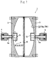
- Said reactor 1 is shown in more detail in figure 7, from which it can be seen that the reactor comprises reactor structural components 2 and 3 provided respectively with a gas supply joint 4 and a moisture gas take-out joint 5.
- Said gas supply joint defines a gas feed passage 4a, and the reactor 1 accommodates a reflector 9 that opposes said gas feed passage 4a.
- a further reflector 12 is provided within the reactor, which further reflector 12 opposes a gas outlet passage 5a that is defined by said take-out joint 5.
- a filter 10 is provided generally in the middle of the reactor 1, and the inside wall of the reactor structural component 3 is provided With a platinum coated catalyst layer 13.
- Said platinum coated catalyst layer 13 has a double layer construction, comprising a barrier coat 13a with a platinum coat 13b formed thereupon.
- Said barrier coat 13a is formed of a nitride such as TiN, on which the platinum coat 13b is fixed by vapour deposition or ion coating.
- Hydrogen and oxygen are fed into the reactor 1 through said gas feed passage 4a and are diffused by gas diffusion means 8 comprising the reflector 9, the filter 10 and the further reflector 12. Said gas mixture contacts said platinum coated catalyst layer 13, which causes or allows the generation of hydrogen and oxygen free radicals. Said hydrogen and oxygen free radicals react very quickly with each other at temperatures lower than ignition point to produce water molecules without undergoing combustion.
- the flow rates of the hydrogen and oxygen into the reactor 1 are set respectively to, for example, about 1000 and 600 cm 3 /min, such that the mixture is typically about 20% wt oxygen rich.
- the gas supply pressure of oxygen and hydrogen is set in the range 1.0 to 3.0kg/cm 2 to produce about 1000cm 3 /min of moisture.
- the reactor 1 typically has an outer diameter of about 114mm, a wall thickness of about 31mm, and an internal volume of about 86cm 3 .
- Said platinum coated catalyst layer may have a surface area of about 99cm 2 . Though very small in size as shown, said reactor can produce in excess of 1000cm 3 /min of water vapour.
- an O 2 -moisture mixer Mx2 Downstream of the outlet of the reactor 1 is provided an O 2 -moisture mixer Mx2, where the moisture can be mixed with oxygen in any desired ratio and thus diluted.
- Fig. 6 illustrates an operation in which a 20 percent oxygen-rich gas mixture is fed into the reactor 1.
- Said reactor 1 could alternatively be operated with a hydrogen-rich gas mixture.
- an H 2 -moisture mixer Mx1 would be provided instead of the O 2 -moisture mixer Mx2.
- Said preheater coils H 0 and H 1 are arranged respectively for heating the gas mixture and oxygen to a temperature not higher than about 200°C.
- Said reactor 1 may also be provided with a heater and, optionally, a cooler such that if the heat generated by the reaction increases the temperature in the reactor to over say 500°C, the cooler is actuated to reduce the temperature below 500°C.
- the gas mixture in the mixer Mx2 is maintained at a temperature of about 120°C to prevent water from condensing on the pipe wall.
- a heater is provided as necessary.
- the mass flow controllers MFC1 to MFC5 and temperature controllers are set to provide predetermined gas mass flow rates, the valves V2 and V5 are opened, and the valves V1, V3 and V4 are closed to purge the system with nitrogen.
- valves V2 and V5 are then closed. Contemporaneously, or after a short time, the valves V3 and V4 are opened to feed oxygen into the system. At the same time, or after a further short time, the valve V1 is opened to feed hydrogen into the system.
- the oxygen and hydrogen molecules are radicalized, and the resulting free radicals react with each other to produce about 1000 cm 3 /min of moisture gas, which is supplied to the semiconductor manufacturing facility, SM.
- Said mass flow controllers MFC1 to MFC5 are constituted such that the gas flow rates reach their pre-set flow rates as soon as possible. That is, the oxygen and hydrogen flow rates reach their set levels within about one second.
- the moisture generator illustrated in Fig. 6 is capable of generating in excess of about 1000cm 3 /min high-purity water.
- the amount of moisture to be generated and supplied can be controlled relatively easily and with high precision by regulating the supply of oxygen and hydrogen.
- the reactor does not allow the flow rate of moisture to be controlled when said moisture is generated in very small quantities.
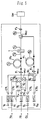
- Fig. 8 shows testing apparatus which we have devised to test the response characteristics of the apparatus of Fig. 6 for the generation of moisture. Experiments were conducted using this testing apparatus, and the response characteristics of the apparatus were determined with the production of moisture kept at very low levels.
- MFC1 to MFC3 indicate mass flow controllers; V1 to V6 are valves; SV is a suction-regulating valve; E is a quadruple mass spectrometer (Q-mass spectrometer); P is a vacuum pump (rotary pump); D is a turbo-molecular pump; and R is a moisture-collecting reservoir in which moisture is condensed at room temperature and collected.
- Said mass flow controllers MFC1 to MFC3 are so-called 'quick-start' type mass flow controllers, and are designed such that the hydrogen and oxygen flow rates O 2 will reach their pre-set flow rates very quickly.
- the flow rates of hydrogen, oxygen and nitrogen were first set to the levels in the four test cases shown below in Table 1 by means of the mass flow controllers MFC1 to MFC3.
- concentration of the gases in the generated moisture and the generated amount of water were determined using the Q-mass spectrometer E.
- the valves V1 to V3 were actuated as follows: At start-up of the moisture generator, the valve V3 was closed and valve V2 was opened. Two seconds later, V1 was opened to produce moisture for one minute. When the moisture generation was to be ended, the valve V1 was closed, and two seconds after that, the valve V2 was closed, and the valve V3 was then opened to feed nitrogen to the reactor 1.
- the Q-mass spectrometer used was the model MSQ-150A Quadruple Mass Analyzer manufactured by ULVAC CORPORATION, Japan.
- the supply pressure was set to 2kgf/cm 2 for hydrogen, 2kgf/cm 2 for oxygen and 7kgf/cm 2 for nitrogen (all gauge pressures).
- Fig.9 shows the results of the four tests.
- the peak rate of moisture generation (P) was the same in each case.
- the amount of moisture generated when the moisture generation was small was almost the same in the initial stage irrespective of the flow rates of oxygen and hydrogen.
- a reason why all four cases peak at almost the same water vapour level in the moisture generation response curve may be that hydrogen remains trapped in the pipe line, the mass flow controller MFC1, the valve V1 and in other parts of the hydrogen gas supply system when a cycle is over. When the valve V1 is opened in the next cycle, this residual hydrogen flows into the reactor 1 where it is converted into water, thus creating a peak in the moisture generation response curve.
- the concentration curve of hydrogen peaks at H2'. This may be because part of the water vapour led into the Q-mass spectrometer E decomposes into H 2 +ions in the gas ionizer within the spectrometer E, and those ions manifest an apparently higher concentration of hydrogen.
- An object of the present invention is to alleviate some or all of the problems encountered with the prior moisture generator.
- the flow of the other gas is controlled so that its mass flow rate increases to the respective preset level at a substantially constant rate of increase.
- the time taken before the pre-set flow rate is reached may be greater than 1 second, typically 1 - 10 seconds (e.g 2, 3, 4, 5, 6, 7, 8 or 9 seconds).
- the "start-up" period for the flow of said other gas is 5 - 6 seconds.
- said other gas is diverted for a period of more than 1 second after flow of said other gas is commenced; typically 1 - 10 seconds. In some embodiments, said other gas may be diverted for 5 - 6 seconds. Thereafter said other gas is supplied to the reactor.
- said water vapour is discarded for a period of more than 1 second after the generation of water vapour commences; typically 1 - 10 seconds. In some embodiments, said water vapour may be discarded for 5 - 6 seconds. Therafter said water vapour may be supplied continuously to means utilising said water vapours such, for example, as semiconductor manufacturing plant.
- Yet another aspect of the invention comprehends apparatus for generating water vapour as claimed in claim 13.
- Yet another aspect of the invention comprises apparatus for generating water vapour as claimed in claim 17.
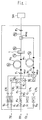
- MFC1 to MFC5 are flow controllers such as mass flow controller; V1 to V10 are valves; T1 to T6 are thermocouples for measurement of temperature; CV1 to CV5 are check valves; F1 to F3 are filters; H1 and H2 are gas heater coils; Mx1 is an O 2 -H 2 O mixer; Mx2 is an O 2 -H 2 O mixer.
- 1 is a reactor for generation of moisture; and SM is a semiconductor manufacturing facility, such, for example, as an oxidation chamber to which generated moisture is supplied.
- Said moisture generator is similar to the one shown in Fig. 6, except that it is provided with valves V6 to V10 and uses a gradually-opening or slow-start mass flow controller MFC1 as mass flow controller.
- the mass flow controller MFC1 on the hydrogen gas supply line is so constituted that after hydrogen gas has started to be supplied to the primary or upstream side at a pressure of 1.0 to 3.0kgf/cm 2 , the flow rate of hydrogen on the secondary or downstream side is gradually increased and reaches a specific pre-set level in some one to ten seconds.
- the mass flow controller MFC1 is a variable flow controller, such that the length of the "start-up" period at which the flow rate of gas is increased from 200 to pre-set level can be adjusted.
- a valve V8 is provided on the inlet side of the mass flow controller MFC1 on the hydrogen supply line. By connecting this valve V8 directly with the mass flow controller MFC1, the dead space between the two is minimized.
- the mass flow controllers MFC1 to MFC5 and temperature controllers are first set to predetermined values.
- the valves V2, V5, V6 and V7 are then opened, and the valves V1, V3, V4, V8, V9 and V10 are closed to purge the system with nitrogen.
- valves V2 and V5 are closed, and at the same time, or after a short time, the valves V3, V4, V9 and V10 are opened to feed oxygen into the system.
- valves V1 and V8 are opened to feed the hydrogen into the system.
- the mass flow controller MFC1 is of the 'slow-start' type, and the hydrogen flow rate through the valve V1 to mix with oxygen is not increased as suddenly as in the prior art system, but gradually increases according to the flow rate increase characteristics the mass flow controller MFC1.
- the rate of increase of the hydrogen flow rate through the mass flow controller MFC1 is such that the set flow rate - about 1-50cm 3 /min is reached in about 1-10 seconds, preferably 5-6 seconds. Any remaining hydrogen trapped in inside spaces of the mass flow controller MFC1, pipe line P n and/or the valve V1 will therefore not be pushed into the reactor all at once.
- Fig. 3 shows the moisture generation response characteristics curves obtained with the reactor 1 for generation of moisture in the experimental arrangement shown in Fig. 2, in which a 'slow-start' type mass controller was used as mass flow controller MFC1.
- the valves were actuated as follows: At start-up, the valves V2 and V7 were closed while the valves V3 and V9 were opened. Two seconds later, the valves V1 and V8 were opened. Finally, the valves V1 and V8 were closed, and two seconds later the valves V3 and V9 were closed, and the valves V2 and V7 were opened.
- the other conditions including the amount of hydrogen supplied were the same as those used in the testing the response characteristics shown in Fig. 9, and in addition the rate of increase of the flow rate provided by the mass flow controller MFC1 was set such that the flow rate of hydrogen would increase and reach the set levels of 5, 10, 20 and 50cm 3 /min (starting from 0cm 3 /min) in about 5 seconds.
- the initial generation of water vapour is regulated at the respective set levels - 5,10,20 or 50 cm 3 /min - as is clear from Fig. 3.
- the moisture generation that is, the mass flow rate of the moisture supply to a semiconductor manufacturing line for example, can be controlled precisely.
- Example 1 precludes any sudden rush into the reactor of hydrogen trapped in inside spaces of the flow controller and/or hydrogen pipe line which occurs when fresh hydrogen is supplied to the inlet side of the flow controller. Thus there is no concern that the generation of moisture will rise out of control if the generated amount is very small. Thus, the production of moisture at very low mass flow rates can be controlled with very high precision.
- Example 1 above relates to 'oxygen-rich' generation of moisture in which a relatively large amount of oxygen and a relatively small amount of hydrogen are fed into the reactor 1, and a mixture of oxygen and water vapour flows out of the moisture outlet 5.
- Example 2 'hydrogen-rich' generation of moisture (in which a relatively large amount of hydrogen and a relatively small amount of oxygen are fed into the reactor 1, and a mixture of hydrogen and moisture is taken out of the moisture outlet) is provided with high precision, as in the oxygen-rich operation, even when the moisture generation is small at 5-50cm 3 /min. This is accomplished by regulating the supply of oxygen using a slow-start, or gradually opening, flow controller such that the oxygen flow rate reaches a specific flow level starting from zero in a certain time - typically 1-10 seconds.
- the slow start-up mass flow controller may be any such, optionally adjustable, controller known and available to those skilled in the art.
- the flow controller may be of any type, including for example a pressure-type flow controller.
- hydrogen and oxygen may be fed into the reactor 1 at ratio a stoichiometric of 2:1 such that the gas exhausted through the outlet consists exclusively and nearly exclusively of water vapour (steam).
- Fig. 4 shows the configuration of apparatus for the generation of moisture according to Example 3.
- a branch pipe S is provided on the moisture outlet side of the apparatus for generation of moisture, and an escape valve 13 is provided in the branch pipe S.
- Switch-over valves V11 and V12, and a purging pipe P N are provided immediately at the upstream side of the semiconductor manufacturing line SM.
- the arrangements in Fig. 4 are otherwise the same as those shown in Fig. 1.
- nitrogen is initially fed to the semiconductor manufacturing line SM through the purging pipe Pn for purging the apparatus.
- specific amounts of oxygen and hydrogen are fed into the reactor for generation of moisture.
- the escape valve V13 is set to an open position, such that the moisture generated initially is discharged from the apparatus to the surroundings. When the rate of moisture generation has stabilized, said escape valve V13 is closed, the switch-over valve V11 is closed, and the switch-over valve V12 is opened to feed subsequently generated moisture to the semiconductor manufacturing line SM at the pre-determined rate.
- the amount of moisture discharged through the escape valve is approximately equal to the volume of moisture produced at the peak point of moisture generation as shown in Fig. 9.
- Example 3 the consumption of oxygen and hydrogen rise, because excessive moisture produced is discharged to the atmosphere before the supply of moisture to the semiconductor manufacturing line SM is started.
- the flow of moisture to the semiconductor manufacturing line SM can be controlled with very high precision.
- Example 3 the moisture generated initially in the reactor 1, which is generated at a rate exceeding the desired rate, is discharged to the outside through the escape valve.
- the supply of moisture to the line SM begins when the moisture generation has stabilized.
- Fig. 5 shows the arrangement of apparatus for the generation of moisture according to Example 4 of the present invention, in which a branch pipe S is connected to the line on the outlet side of the mass flow controller MFC1 for feeding hydrogen, and an escape valve V14 is provided on said branch pipe S.
- Example 4 the escape valve 14 is left open beforehand. Thus any excessive partial pressure of hydrogen trapped in the mass flow controller MFC1 and the pipe line is discharged almost completely. When hydrogen is subsequently is fed into the reactor 1 for the generation of moisture, there will be no sudden rush of hydrogen into the reactor 1, as in the prior art apparatus for generation of moisture as in Fig. 6.
- the flow of moisture from the reactor 1 can thus be controlled with very high precision, even where the flow is very low.
- the apparatus of Example 4 is configured such that a branch pipe to permit hydrogen to escape is provided on the outlet side of the flow controller which controls the flow of hydrogen.
- An escape valve is left open before hydrogen is fed into the inlet side of the reactor for generation of moisture, so that excessive hydrogen trapped inside is released through the escape valve.
- any residual hydrogen is prevented from flowing suddenly into the reactor 1. According to this arrangement, there will be no unwanted peak of moisture concentration in the initial stage, and even if the moisture of a small amount is generated under oxygen-rich conditions, the supply to the semiconductor manufacturing line can be controlled with great precision.
- Example 4 'oxygen-rich' moisture generation is described.
- the process of Example 4 can be modified to provide 'hydrogen-rich' moisture generation (Example 5) or the production of water vapour which is neither hydrogen rich nor oxygen rich by supplying hydrogen and oxygen to the reactor 1 in ratio of about 2 : 1 (Example 6).
- a branch pipe S is provided on the downstream side of the oxygen flow controller MFC3. Excessive pressure of oxygen trapped between the flow controller MFC3 and the valve V3 is discharged in advance through the branch pipe S and the escape valve. Sudden flow of oxygen into the reactor 1 is thus prevented when the feeding of oxygen to the reactor is started. When the flow of oxygen has stabilized to a specific predetermined level, oxygen is introduced into the reactor 1.
Landscapes
- Engineering & Computer Science (AREA)
- Chemical & Material Sciences (AREA)
- Organic Chemistry (AREA)
- Physics & Mathematics (AREA)
- Inorganic Chemistry (AREA)
- Sustainable Energy (AREA)
- Sustainable Development (AREA)
- Thermal Sciences (AREA)
- Mechanical Engineering (AREA)
- General Engineering & Computer Science (AREA)
- Life Sciences & Earth Sciences (AREA)
- Combustion & Propulsion (AREA)
- General Physics & Mathematics (AREA)
- Condensed Matter Physics & Semiconductors (AREA)
- Manufacturing & Machinery (AREA)
- Computer Hardware Design (AREA)
- Microelectronics & Electronic Packaging (AREA)
- Power Engineering (AREA)
- Formation Of Insulating Films (AREA)
- Control Of Non-Electrical Variables (AREA)
- Fuel Cell (AREA)
- Oxygen, Ozone, And Oxides In General (AREA)
Applications Claiming Priority (2)
| Application Number | Priority Date | Filing Date | Title |
|---|---|---|---|
| JP34028397A JP3644810B2 (ja) | 1997-12-10 | 1997-12-10 | 少流量の水分供給方法 |
| JP34028397 | 1997-12-10 |
Publications (3)
| Publication Number | Publication Date |
|---|---|
| EP0922905A2 true EP0922905A2 (de) | 1999-06-16 |
| EP0922905A3 EP0922905A3 (de) | 2001-11-14 |
| EP0922905B1 EP0922905B1 (de) | 2005-03-30 |
Family
ID=18335466
Family Applications (1)
| Application Number | Title | Priority Date | Filing Date |
|---|---|---|---|
| EP98310060A Expired - Lifetime EP0922905B1 (de) | 1997-12-10 | 1998-12-08 | Verfahren zur Erzeugung von Wasserdampf |
Country Status (9)
| Country | Link |
|---|---|
| US (1) | US6334962B1 (de) |
| EP (1) | EP0922905B1 (de) |
| JP (1) | JP3644810B2 (de) |
| KR (1) | KR100361958B1 (de) |
| CA (1) | CA2255370C (de) |
| DE (1) | DE69829543T2 (de) |
| IL (1) | IL127395A (de) |
| SG (1) | SG74106A1 (de) |
| TW (1) | TW386187B (de) |
Cited By (3)
| Publication number | Priority date | Publication date | Assignee | Title |
|---|---|---|---|---|
| WO2002086958A1 (de) * | 2001-04-23 | 2002-10-31 | Mattson Thermal Products Gmbh | Verfahren und vorrichtung zum erzeugen von prozessgasen |
| WO2003016213A1 (en) * | 2001-08-13 | 2003-02-27 | Ultra Clean Technology Systems And Services Inc. | Catalytic reactor apparatus and method for generating high purity water vapor |
| SG94873A1 (en) * | 1999-08-06 | 2003-03-18 | Fujikin Kk | Reactor for generating high purity moisture |
Families Citing this family (6)
| Publication number | Priority date | Publication date | Assignee | Title |
|---|---|---|---|---|
| TW462093B (en) * | 1997-03-05 | 2001-11-01 | Hitachi Ltd | Method for manufacturing semiconductor integrated circuit device having a thin insulative film |
| CN1202987C (zh) * | 2000-06-05 | 2005-05-25 | 株式会社富士金 | 水分发生用反应炉 |
| JP2002274812A (ja) * | 2001-03-23 | 2002-09-25 | Fujikin Inc | 水分発生用反応炉 |
| CN102287851A (zh) * | 2011-07-13 | 2011-12-21 | 上海先进半导体制造股份有限公司 | 炉管点火方法 |
| US9454158B2 (en) | 2013-03-15 | 2016-09-27 | Bhushan Somani | Real time diagnostics for flow controller systems and methods |
| US10983537B2 (en) | 2017-02-27 | 2021-04-20 | Flow Devices And Systems Inc. | Systems and methods for flow sensor back pressure adjustment for mass flow controller |
Citations (2)
| Publication number | Priority date | Publication date | Assignee | Title |
|---|---|---|---|---|
| EP0209065A2 (de) * | 1985-07-15 | 1987-01-21 | Dainippon Screen Mfg. Co., Ltd. | Verfahren zum Zuführen von wasserdampfhaltigem Sauerstoffgas zur Oberflächenbehandlung von Halbleiterwaffel |
| CA2244688A1 (en) * | 1996-01-29 | 1997-08-07 | Fujikin Incorporated | Method for generating moisture, reactor for generating moisture, method for controlling temperature of reactor for generating moisture, and method for forming platinum-coated catalyst layer |
Family Cites Families (8)
| Publication number | Priority date | Publication date | Assignee | Title |
|---|---|---|---|---|
| US2582885A (en) * | 1948-08-23 | 1952-01-15 | Baker & Co Inc | Method of removing free oxygen or free hydrogen from a gaseous medium |
| GB858079A (en) * | 1959-01-13 | 1961-01-04 | Engelhard Hanovia Inc | Improvements in or relating to the combination of hydrogen and oxygen |
| US3240554A (en) * | 1961-02-27 | 1966-03-15 | Air Reduction | Method of removing oxygen from relatively inert crude gases |
| US3535074A (en) * | 1965-10-29 | 1970-10-20 | Hitachi Ltd | Method and apparatus for purifying crude inert gases |
| US3630956A (en) * | 1969-04-01 | 1971-12-28 | Air Prod & Chem | Method of producing gases with controlled concentrations of water vapor |
| JP3331636B2 (ja) * | 1992-10-05 | 2002-10-07 | 忠弘 大見 | 水分発生方法 |
| KR960039200A (ko) * | 1995-04-13 | 1996-11-21 | 김광호 | 산화장치 및 산화방법 |
| JP3421483B2 (ja) * | 1995-08-25 | 2003-06-30 | 株式会社東芝 | 半導体装置の製造方法 |
-
1997
- 1997-12-10 JP JP34028397A patent/JP3644810B2/ja not_active Expired - Lifetime
-
1998
- 1998-12-03 IL IL12739598A patent/IL127395A/en not_active IP Right Cessation
- 1998-12-08 DE DE69829543T patent/DE69829543T2/de not_active Expired - Lifetime
- 1998-12-08 EP EP98310060A patent/EP0922905B1/de not_active Expired - Lifetime
- 1998-12-09 SG SG1998005388A patent/SG74106A1/en unknown
- 1998-12-09 CA CA002255370A patent/CA2255370C/en not_active Expired - Fee Related
- 1998-12-09 US US09/207,763 patent/US6334962B1/en not_active Expired - Fee Related
- 1998-12-10 KR KR10-1998-0054071A patent/KR100361958B1/ko not_active IP Right Cessation
-
1999
- 1999-01-19 TW TW087120549A patent/TW386187B/zh not_active IP Right Cessation
Patent Citations (2)
| Publication number | Priority date | Publication date | Assignee | Title |
|---|---|---|---|---|
| EP0209065A2 (de) * | 1985-07-15 | 1987-01-21 | Dainippon Screen Mfg. Co., Ltd. | Verfahren zum Zuführen von wasserdampfhaltigem Sauerstoffgas zur Oberflächenbehandlung von Halbleiterwaffel |
| CA2244688A1 (en) * | 1996-01-29 | 1997-08-07 | Fujikin Incorporated | Method for generating moisture, reactor for generating moisture, method for controlling temperature of reactor for generating moisture, and method for forming platinum-coated catalyst layer |
Cited By (3)
| Publication number | Priority date | Publication date | Assignee | Title |
|---|---|---|---|---|
| SG94873A1 (en) * | 1999-08-06 | 2003-03-18 | Fujikin Kk | Reactor for generating high purity moisture |
| WO2002086958A1 (de) * | 2001-04-23 | 2002-10-31 | Mattson Thermal Products Gmbh | Verfahren und vorrichtung zum erzeugen von prozessgasen |
| WO2003016213A1 (en) * | 2001-08-13 | 2003-02-27 | Ultra Clean Technology Systems And Services Inc. | Catalytic reactor apparatus and method for generating high purity water vapor |
Also Published As
| Publication number | Publication date |
|---|---|
| DE69829543D1 (de) | 2005-05-04 |
| SG74106A1 (en) | 2000-07-18 |
| US6334962B1 (en) | 2002-01-01 |
| CA2255370A1 (en) | 1999-06-10 |
| JPH11171503A (ja) | 1999-06-29 |
| TW386187B (en) | 2000-04-01 |
| EP0922905A3 (de) | 2001-11-14 |
| KR100361958B1 (ko) | 2003-04-26 |
| CA2255370C (en) | 2002-07-23 |
| KR19990062953A (ko) | 1999-07-26 |
| EP0922905B1 (de) | 2005-03-30 |
| JP3644810B2 (ja) | 2005-05-11 |
| DE69829543T2 (de) | 2006-03-30 |
| IL127395A0 (en) | 1999-10-28 |
| IL127395A (en) | 2001-06-14 |
Similar Documents
| Publication | Publication Date | Title |
|---|---|---|
| EP0922905B1 (de) | Verfahren zur Erzeugung von Wasserdampf | |
| EP0922667B1 (de) | Verfahren zur erzeugung von wasser für die halbleiterherstellung | |
| US5840368A (en) | Apparatus for forming low-temperature oxide films and method of forming low-temperature oxide films | |
| KR19990082090A (ko) | 수분발생방법과 수분발생용 반응로와, 수분발생용 반응로의온도제어방법 및 백금코팅촉매층의 형성방법 | |
| US5431736A (en) | Method for transforming a liquid flow into a gas flow and a device for implementing the method | |
| US5990014A (en) | In situ wafer cleaning process | |
| JP3563950B2 (ja) | 水素含有排ガス処理装置 | |
| WO2001010774A1 (fr) | Dispositif de generation/distribution d'humidite et reacteur generateur d'humidite | |
| EP1104012B1 (de) | Verfahren zur Herstellung einer Oxidschicht auf einem Halbleiterwafer | |
| EP0720510B1 (de) | Verfahren und vorrichtung zur kontrollierten herstellung und zuführung einer gasatmosphäre mit mindestens zwei komponenten und verwendung in anlagen für thermische oder karburierende behandlung | |
| TW200931489A (en) | Method of treating a gas stream | |
| IL141988A (en) | Process for supplying moisture at low flow rate | |
| JPH04214870A (ja) | 化学気相成長装置 | |
| KR0170717B1 (ko) | 이중 배관의 배기 가스 유입관을 갖는 가스 스크러버 | |
| JPH08279466A (ja) | 半導体製造装置 | |
| US4989840A (en) | Controlling high humidity atmospheres in furnace main body | |
| EP0303832A1 (de) | Verfahren und Einrichtung zur Verringerung der Konzentration von Stickoxiden | |
| JPH05291144A (ja) | 化学気相成長装置及びその気化器 | |
| KR100711992B1 (ko) | 반도체 물질로 제작된 웨이퍼상에 산화물층을 형성하는방법 및 장치 | |
| IL141729A (en) | Method for generating water for semiconductor production | |
| US4239191A (en) | Apparatus for controlling combustion in a metal melting furnace | |
| JP3611495B2 (ja) | 減圧型水分発生供給装置 | |
| JP2001274147A (ja) | 半導体製造装置 | |
| JPS6210358B2 (de) |
Legal Events
| Date | Code | Title | Description |
|---|---|---|---|
| PUAI | Public reference made under article 153(3) epc to a published international application that has entered the european phase |
Free format text: ORIGINAL CODE: 0009012 |
|
| 17P | Request for examination filed |
Effective date: 19990107 |
|
| AK | Designated contracting states |
Kind code of ref document: A2 Designated state(s): AT BE CH CY DE DK ES FI FR GB GR IE IT LI LU MC NL PT SE Kind code of ref document: A2 Designated state(s): CH DE FR GB IT LI NL |
|
| AX | Request for extension of the european patent |
Free format text: AL;LT;LV;MK;RO;SI |
|
| PUAL | Search report despatched |
Free format text: ORIGINAL CODE: 0009013 |
|
| AK | Designated contracting states |
Kind code of ref document: A3 Designated state(s): AT BE CH CY DE DK ES FI FR GB GR IE IT LI LU MC NL PT SE |
|
| AX | Request for extension of the european patent |
Free format text: AL;LT;LV;MK;RO;SI |
|
| RIC1 | Information provided on ipc code assigned before grant |
Free format text: 7F 22B 1/00 A, 7C 01B 5/00 B, 7H 01L 21/316 B |
|
| AKX | Designation fees paid |
Free format text: CH DE FR GB IT LI NL |
|
| 17Q | First examination report despatched |
Effective date: 20031119 |
|
| GRAP | Despatch of communication of intention to grant a patent |
Free format text: ORIGINAL CODE: EPIDOSNIGR1 |
|
| RTI1 | Title (correction) |
Free format text: IMPROVEMENTS IN OR RELATING TO A METHOD FOR THE GENERATION OF WATER VAPOUR |
|
| GRAS | Grant fee paid |
Free format text: ORIGINAL CODE: EPIDOSNIGR3 |
|
| GRAA | (expected) grant |
Free format text: ORIGINAL CODE: 0009210 |
|
| AK | Designated contracting states |
Kind code of ref document: B1 Designated state(s): CH DE FR GB IT LI NL |
|
| REG | Reference to a national code |
Ref country code: GB Ref legal event code: FG4D |
|
| REG | Reference to a national code |
Ref country code: CH Ref legal event code: EP |
|
| REF | Corresponds to: |
Ref document number: 69829543 Country of ref document: DE Date of ref document: 20050504 Kind code of ref document: P |
|
| REG | Reference to a national code |
Ref country code: CH Ref legal event code: NV Representative=s name: E. BLUM & CO. PATENTANWAELTE |
|
| PLBE | No opposition filed within time limit |
Free format text: ORIGINAL CODE: 0009261 |
|
| STAA | Information on the status of an ep patent application or granted ep patent |
Free format text: STATUS: NO OPPOSITION FILED WITHIN TIME LIMIT |
|
| ET | Fr: translation filed | ||
| 26N | No opposition filed |
Effective date: 20060102 |
|
| REG | Reference to a national code |
Ref country code: CH Ref legal event code: PFA Owner name: HITACHI, LTD. Free format text: HITACHI, LTD.#6, KANDA SURUGADAI 4-CHOME#CHIYODA-KU, TOKYO 101 (JP) $ FUJIKIN INC.#2-3-2 ITACHIBORI 2-CHOME#NISHI-KU, OSAKA (JP) -TRANSFER TO- HITACHI, LTD.#6, KANDA SURUGADAI 4-CHOME#CHIYODA-KU, TOKYO 101 (JP) $ FUJIKIN INC.#2-3-2 ITACHIBORI 2-CHOME#NISHI-KU, OSAKA (JP) |
|
| PGFP | Annual fee paid to national office [announced via postgrant information from national office to epo] |
Ref country code: NL Payment date: 20071130 Year of fee payment: 10 |
|
| PGFP | Annual fee paid to national office [announced via postgrant information from national office to epo] |
Ref country code: CH Payment date: 20071130 Year of fee payment: 10 |
|
| PGFP | Annual fee paid to national office [announced via postgrant information from national office to epo] |
Ref country code: IT Payment date: 20081210 Year of fee payment: 11 |
|
| PGFP | Annual fee paid to national office [announced via postgrant information from national office to epo] |
Ref country code: FR Payment date: 20081127 Year of fee payment: 11 |
|
| PGFP | Annual fee paid to national office [announced via postgrant information from national office to epo] |
Ref country code: GB Payment date: 20081224 Year of fee payment: 11 |
|
| REG | Reference to a national code |
Ref country code: CH Ref legal event code: PL |
|
| NLV4 | Nl: lapsed or anulled due to non-payment of the annual fee |
Effective date: 20090701 |
|
| PG25 | Lapsed in a contracting state [announced via postgrant information from national office to epo] |
Ref country code: LI Free format text: LAPSE BECAUSE OF NON-PAYMENT OF DUE FEES Effective date: 20081231 Ref country code: CH Free format text: LAPSE BECAUSE OF NON-PAYMENT OF DUE FEES Effective date: 20081231 |
|
| PG25 | Lapsed in a contracting state [announced via postgrant information from national office to epo] |
Ref country code: NL Free format text: LAPSE BECAUSE OF NON-PAYMENT OF DUE FEES Effective date: 20090701 |
|
| GBPC | Gb: european patent ceased through non-payment of renewal fee |
Effective date: 20091208 |
|
| REG | Reference to a national code |
Ref country code: FR Ref legal event code: ST Effective date: 20100831 |
|
| PG25 | Lapsed in a contracting state [announced via postgrant information from national office to epo] |
Ref country code: FR Free format text: LAPSE BECAUSE OF NON-PAYMENT OF DUE FEES Effective date: 20091231 |
|
| PG25 | Lapsed in a contracting state [announced via postgrant information from national office to epo] |
Ref country code: GB Free format text: LAPSE BECAUSE OF NON-PAYMENT OF DUE FEES Effective date: 20091208 |
|
| PG25 | Lapsed in a contracting state [announced via postgrant information from national office to epo] |
Ref country code: IT Free format text: LAPSE BECAUSE OF NON-PAYMENT OF DUE FEES Effective date: 20091208 |
|
| PGFP | Annual fee paid to national office [announced via postgrant information from national office to epo] |
Ref country code: DE Payment date: 20120131 Year of fee payment: 14 |
|
| PG25 | Lapsed in a contracting state [announced via postgrant information from national office to epo] |
Ref country code: DE Free format text: LAPSE BECAUSE OF NON-PAYMENT OF DUE FEES Effective date: 20130702 |
|
| REG | Reference to a national code |
Ref country code: DE Ref legal event code: R119 Ref document number: 69829543 Country of ref document: DE Effective date: 20130702 |