EP0209065A2 - Verfahren zum Zuführen von wasserdampfhaltigem Sauerstoffgas zur Oberflächenbehandlung von Halbleiterwaffel - Google Patents
Verfahren zum Zuführen von wasserdampfhaltigem Sauerstoffgas zur Oberflächenbehandlung von Halbleiterwaffel Download PDFInfo
- Publication number
- EP0209065A2 EP0209065A2 EP86109328A EP86109328A EP0209065A2 EP 0209065 A2 EP0209065 A2 EP 0209065A2 EP 86109328 A EP86109328 A EP 86109328A EP 86109328 A EP86109328 A EP 86109328A EP 0209065 A2 EP0209065 A2 EP 0209065A2
- Authority
- EP
- European Patent Office
- Prior art keywords
- hydrogen
- chamber
- oxygen gas
- combustion chamber
- gas
- Prior art date
- Legal status (The legal status is an assumption and is not a legal conclusion. Google has not performed a legal analysis and makes no representation as to the accuracy of the status listed.)
- Granted
Links
Images

Classifications
-
- C—CHEMISTRY; METALLURGY
- C23—COATING METALLIC MATERIAL; COATING MATERIAL WITH METALLIC MATERIAL; CHEMICAL SURFACE TREATMENT; DIFFUSION TREATMENT OF METALLIC MATERIAL; COATING BY VACUUM EVAPORATION, BY SPUTTERING, BY ION IMPLANTATION OR BY CHEMICAL VAPOUR DEPOSITION, IN GENERAL; INHIBITING CORROSION OF METALLIC MATERIAL OR INCRUSTATION IN GENERAL
- C23C—COATING METALLIC MATERIAL; COATING MATERIAL WITH METALLIC MATERIAL; SURFACE TREATMENT OF METALLIC MATERIAL BY DIFFUSION INTO THE SURFACE, BY CHEMICAL CONVERSION OR SUBSTITUTION; COATING BY VACUUM EVAPORATION, BY SPUTTERING, BY ION IMPLANTATION OR BY CHEMICAL VAPOUR DEPOSITION, IN GENERAL
- C23C8/00—Solid state diffusion of only non-metal elements into metallic material surfaces; Chemical surface treatment of metallic material by reaction of the surface with a reactive gas, leaving reaction products of surface material in the coating, e.g. conversion coatings, passivation of metals
- C23C8/06—Solid state diffusion of only non-metal elements into metallic material surfaces; Chemical surface treatment of metallic material by reaction of the surface with a reactive gas, leaving reaction products of surface material in the coating, e.g. conversion coatings, passivation of metals using gases
- C23C8/08—Solid state diffusion of only non-metal elements into metallic material surfaces; Chemical surface treatment of metallic material by reaction of the surface with a reactive gas, leaving reaction products of surface material in the coating, e.g. conversion coatings, passivation of metals using gases only one element being applied
- C23C8/10—Oxidising
- C23C8/16—Oxidising using oxygen-containing compounds, e.g. water, carbon dioxide
-
- C—CHEMISTRY; METALLURGY
- C01—INORGANIC CHEMISTRY
- C01B—NON-METALLIC ELEMENTS; COMPOUNDS THEREOF; METALLOIDS OR COMPOUNDS THEREOF NOT COVERED BY SUBCLASS C01C
- C01B5/00—Water
-
- F—MECHANICAL ENGINEERING; LIGHTING; HEATING; WEAPONS; BLASTING
- F22—STEAM GENERATION
- F22B—METHODS OF STEAM GENERATION; STEAM BOILERS
- F22B1/00—Methods of steam generation characterised by form of heating method
-
- F—MECHANICAL ENGINEERING; LIGHTING; HEATING; WEAPONS; BLASTING
- F22—STEAM GENERATION
- F22B—METHODS OF STEAM GENERATION; STEAM BOILERS
- F22B1/00—Methods of steam generation characterised by form of heating method
- F22B1/003—Methods of steam generation characterised by form of heating method using combustion of hydrogen with oxygen
Definitions
- THE PRESENT INVENTION relates to apparatus for supplying oxygen gas containing uniformly distributed steam of high purity for use in a heat treatment process in which a heated wafer of semiconductor is fed with oxygen gas containing steam and the steam is deposited on the surface of the semiconductor wafer to form an oxide film thereon serving as a protective coat.
- FIG. 7 of the accompanying drawings shows a known oxygen gas feeding apparatus employing a bubbling method.
- oxygen gas is blown into pure water 2 stored in a sealed vessel I in the direction of the arrows in Figure 7, and the oxygen gas dampened by passing through the pure water 2 delivered to a treatment chamber (not shown).
- a vessel or reservoir is used for the storage of the pure water, it is impossible with this known feeder to maintain the purity required in manufacturing semiconductor devices.
- the pure water in the vessel has to be changed or replenished often.
- the quarz tube is elongated so as to put a larger distance between the hydrogen flame and the semiconductor wafer.
- a nozzle of special design is proposed for the introduction of hydrogen gas.
- a separate combustion chamber system is employed wherein the combustion chamber is divided from the semiconductor heat treatment chamber, and the two chambers communicate with each other through a connector.
- the invention aims enable solving of the aforesaid problems and, to this end, provides apparatus for supplying oxygen gas containing steam, comprising a hydrogen gas chamber and a combustion gas chamber separated by a hydrogen permeable membrane of oxidation catalyst, means for introducing oxygen gas into the combustion chamber and means for introducing hydrogen gas into the hydrogen chamber, so that the hydrogen gas diffuses through the catalytic membrane and reacts with the oxygen gas in the combustion chamber to generate steam.
- part of the hydrogen gas induced into the hydrogen chamber is physically adsorpted onto the surface of the hydrogen permeable film of oxidation catalyzer, diffuses through the film uniformly over the surface of the film, and reacts with the excess of oxygen gas present on the opposite side of the film, i.e., in the combustion chamber, to generate steam. Since such oxidative combustion of hydrogen gas takes place as catalytic oxidation, the reaction proceeds gently but steadily at a relatively low temperature, and when the quantity of gas is small, there is no flame. Further, since the oxidation reaction occurs not locally but uniformly over the film, mixing of the steam generated by the reaction is also even.
- the film When the hydrogen permeable film is formed from a catalyst having a property of selectively passing the hydrogen gas alone, the film also provides purification of the hydrogen gas, resulting in hydrogen of high purity. A remaining part of the hydrogen gas which does not pass through the hydrogen permeable film and any impurities are exhausted from the hydrogen chamber through an exhaust tube as bleed gas.
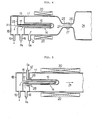
- an oxygen gas feeding apparatus comprises a combustion chamber I made of quarz, in the right head part of which are placed semiconductor wafers (not illustrated) aligned on a supporting board.
- An oxygen gas inlet tube 12 communicates with the combustion chamber I I and is connected to an oxygen gas supply (not illustrated).
- Numeral 13 denotes a hydrogen chamber 13, a part 14 of which projects into the combustion chamber II.
- a diaphragm 15 of the projecting part 14 is formed by a hydrogen permeable membrane or film of oxidation catalyst, which physically adsorps hydrogen gas on its surface and diffuses and transmits the hydrogen while uniformly distributing it all over the film surface.
- This film undertake catalysis at a temperature of 300 - 700 0 C, and generates steam by oxidising the hydrogen.
- a know palladium alloy may be used as the material of the hydrogen permeable film.
- Such a film of palladium alloy is made of palladium (Pd), Silver (Ag) and Gold (Au).
- the catalysts for hydrogen can be performed by Pd alone, but a film of Pd alone lacks strength, and therefore Ag and Au are added to enhance the strength.
- the thickness of the hydrogen permeable film is desirably as thin as possible, but it is usually formed not more than 0.5 mm in thickness considering strength on the other hand.
- the hydrogen chamber is connected to a hydrogen gas inlet pipe 16, which communicates with a hydrogen gas supply (not illustrated).
- the hydrogen chamber 13 also communicates with an exhaust chamber 18 by way of an inner pipe 17 inserted therein, and the exhaust chamber 18 is connected to an outlet pipe 19.
- An external heater 20 is disposed along the outer wall of the combustion chamber I to heat the hydrogen permeable film and the gas generated by reaction. It is also possible to dispose a plurality of projecting portions 14 of the hydrogen chamber 13 in the combustion chamber II ⁇
- the diaphragm 15 composed of the hydrogen permeable film is heated to a temperature of 300 - 700 0 C. Then oxygen gas is introduced from the oxygen gas supply to the combustion chamber I by way of oxygen gas inlet pipe 12. At this time, pressure in the combustion chamber I is no more than I kg/cm 2 . Under these conditions, hydrogen gas is introduced from the hydrogen gas supply source to the hydrogen gas chamber 13 through the hydrogen gas inlet pipe 16. The pressure of the introduced hydrogen gas is higher than the pressure within the combustion chamber I and is, for example, 10 kg/cm 2 .
- a part of the hydrogen gas introduced to the hydrogen gas chamber 13 passes through the diaphragm 15 and reaches the surface of the diagram on the combustion chamber side, where the hydrogen gas reacts with the excess of oxygen gas present in the combustion chamber to generate steam.
- the diaphragm 15 is heated itself by the oxidative reaction. Accordingly, if the quantity of hydrogen gas transmitted through the diaphragm 15 (in other words, the pressure of hydrogen gas supplied to the hydrogen gas chamber 13) is kept at a certain level, heating by the external heater 20 is not necessary since sufficient self-heating by oxidative reaction heat takes place.
- the palladium alloy has the property of refining (purifying) hydrogen as is well known and, even if the hydrogen gas supplied to the chamber 13 contains impurities, those impurities do not pass through the film but hydrogen alone is selectively transmitted.
- steam generated in the combustion chamber I is uniformly mixed with the excess of oxygen gas present in the chamber I I in the form of atmospheric gas and the mixture is sent in the direction 2) to the semiconductor wafer (not illustrated).
- the hydrogen gas not transmitted through the diaphragm 15 and the impurities are discharged from the outlet pipe 19 by way of the inner pipe 17 and exhaust chamber 18.
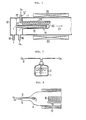
- FIGS 2 and 3 illustrate further respective embodiments of the invention which differ from the apparatus shown in Figure I in having heating means which are not external heaters but internal heaters 22, 23 inserted in the inner pipe 17 disposed in the hydrogen gas chamber 13.
- heating means which are not external heaters but internal heaters 22, 23 inserted in the inner pipe 17 disposed in the hydrogen gas chamber 13.
- the inner pipe 17 itself constitutes part of the heater.
- FIG. 4 shows a further embodiment of the invention, wherein a combustion chamber and a heat treatment chamber for semiconductor wafers are separated.
- the basic structure of the combustion chamber II' is not different from the embodiments described above, but the diameter of its free end is reduced to form a narrow neck portion 25.
- the diameter of an adjacent end of the semiconductor wafer heat treatment chamber 24 is also narrowed to form a neck portion 26 and the two chambers I I' and 24 are joined together by a connector 27 which couples their neck portions 25, 26 together.
- mixed gas composed of steam generated in the combustion chamber I I' and oxygen gas which is the atmospheric gas in the chamber II' flows to the heat treatment chamber 24 in the direction of the arrow 21', and during its passage through the narrowed neck portions 25, 26, the composition of the mixed gas becomes even and uniform.
- an external heater or an internal heater as shown in Figures I to 3 or, as shown in Figure 4, both an external heater 20 and an internal heater 23 may be used.
- FIGS 5 and 6 illustrate yet further respective embodiments of the invention respectively.
- a gas outlet opening 28 of the oxygen gas inlet pipe 12' is disposed around a base portion of the diaphragm 15, so that the oxygen gas introduced into the combustion chamber I from the oxygen gas induction pipe 12' flows along the surface of the diaphragm 15 and cools the diaphragm 15 to prevent it from being overheated by combustion of hydrogen gas.
- an oxygen gas inlet pipe 12' is extended into the combustion chamber II, and an extending pipe portion 29 thereof is disposed alongside the diaphragm.
- a plurality of gas outlets 30 are disposed so as to face the surface of the diaphragm 15.
Landscapes
- Engineering & Computer Science (AREA)
- Chemical & Material Sciences (AREA)
- Organic Chemistry (AREA)
- Mechanical Engineering (AREA)
- Sustainable Development (AREA)
- Sustainable Energy (AREA)
- Physics & Mathematics (AREA)
- Thermal Sciences (AREA)
- Life Sciences & Earth Sciences (AREA)
- General Engineering & Computer Science (AREA)
- Inorganic Chemistry (AREA)
- Combustion & Propulsion (AREA)
- Chemical Kinetics & Catalysis (AREA)
- Materials Engineering (AREA)
- Metallurgy (AREA)
- Separation Using Semi-Permeable Membranes (AREA)
Applications Claiming Priority (2)
| Application Number | Priority Date | Filing Date | Title |
|---|---|---|---|
| JP60156708A JPS62104038A (ja) | 1985-07-15 | 1985-07-15 | 水蒸気含有酸素ガス供給装置 |
| JP156708/85 | 1985-07-15 |
Publications (3)
| Publication Number | Publication Date |
|---|---|
| EP0209065A2 true EP0209065A2 (de) | 1987-01-21 |
| EP0209065A3 EP0209065A3 (en) | 1988-01-13 |
| EP0209065B1 EP0209065B1 (de) | 1990-11-07 |
Family
ID=15633597
Family Applications (1)
| Application Number | Title | Priority Date | Filing Date |
|---|---|---|---|
| EP86109328A Expired - Lifetime EP0209065B1 (de) | 1985-07-15 | 1986-07-08 | Verfahren zum Zuführen von wasserdampfhaltigem Sauerstoffgas zur Oberflächenbehandlung von Halbleiterwaffel |
Country Status (4)
| Country | Link |
|---|---|
| US (1) | US4693208A (de) |
| EP (1) | EP0209065B1 (de) |
| JP (1) | JPS62104038A (de) |
| DE (1) | DE3675444D1 (de) |
Cited By (4)
| Publication number | Priority date | Publication date | Assignee | Title |
|---|---|---|---|---|
| FR2643364A1 (fr) * | 1989-02-22 | 1990-08-24 | Air Liquide | Procede d'elaboration de composants multicouches ceramique-metal et appareil pour sa mise en oeuvre |
| FR2643365A1 (fr) * | 1989-02-22 | 1990-08-24 | Air Liquide | Procede de metallisation de ceramiques et appareil pour sa mise en oeuvr |
| EP0922905A3 (de) * | 1997-12-10 | 2001-11-14 | Fujikin Inc. | Verfahren und Vorrichtung zur Erzeugung von Wasserdampf |
| KR100452159B1 (ko) * | 2002-08-26 | 2004-10-12 | (주) 윈테크 | 반도체 장치의 촉매를 이용한 세정방법 및 이를 수행하기위한시스템 |
Families Citing this family (17)
| Publication number | Priority date | Publication date | Assignee | Title |
|---|---|---|---|---|
| JP2646990B2 (ja) * | 1993-12-28 | 1997-08-27 | 日本電気株式会社 | 水素還元装置およびその方法および水素還元材料 |
| JP3110465B2 (ja) * | 1996-01-29 | 2000-11-20 | 株式会社 フジキン | 水分発生用反応炉と水分発生用反応炉の温度制御方法及び白金コーティング触媒層の形成方法 |
| US6620723B1 (en) | 2000-06-27 | 2003-09-16 | Applied Materials, Inc. | Formation of boride barrier layers using chemisorption techniques |
| US6846516B2 (en) | 2002-04-08 | 2005-01-25 | Applied Materials, Inc. | Multiple precursor cyclical deposition system |
| US6858547B2 (en) * | 2002-06-14 | 2005-02-22 | Applied Materials, Inc. | System and method for forming a gate dielectric |
| US20030232501A1 (en) * | 2002-06-14 | 2003-12-18 | Kher Shreyas S. | Surface pre-treatment for enhancement of nucleation of high dielectric constant materials |
| US20040198069A1 (en) | 2003-04-04 | 2004-10-07 | Applied Materials, Inc. | Method for hafnium nitride deposition |
| US20050252449A1 (en) | 2004-05-12 | 2005-11-17 | Nguyen Son T | Control of gas flow and delivery to suppress the formation of particles in an MOCVD/ALD system |
| US8323754B2 (en) | 2004-05-21 | 2012-12-04 | Applied Materials, Inc. | Stabilization of high-k dielectric materials |
| US8119210B2 (en) | 2004-05-21 | 2012-02-21 | Applied Materials, Inc. | Formation of a silicon oxynitride layer on a high-k dielectric material |
| US7402534B2 (en) | 2005-08-26 | 2008-07-22 | Applied Materials, Inc. | Pretreatment processes within a batch ALD reactor |
| US7798096B2 (en) | 2006-05-05 | 2010-09-21 | Applied Materials, Inc. | Plasma, UV and ion/neutral assisted ALD or CVD in a batch tool |
| US7659158B2 (en) | 2008-03-31 | 2010-02-09 | Applied Materials, Inc. | Atomic layer deposition processes for non-volatile memory devices |
| US8491967B2 (en) | 2008-09-08 | 2013-07-23 | Applied Materials, Inc. | In-situ chamber treatment and deposition process |
| US20100062149A1 (en) | 2008-09-08 | 2010-03-11 | Applied Materials, Inc. | Method for tuning a deposition rate during an atomic layer deposition process |
| DE102012219755A1 (de) * | 2012-10-29 | 2014-04-30 | Thyssenkrupp Marine Systems Gmbh | Verfahren zum Erzeugen von Wasserdampf |
| CN109441665B (zh) * | 2018-12-26 | 2024-05-28 | 同济大学 | 高压气态氢氧喷气式发动机装置 |
Family Cites Families (9)
| Publication number | Priority date | Publication date | Assignee | Title |
|---|---|---|---|---|
| GB1182062A (en) * | 1968-03-19 | 1970-02-25 | Carves Simon Ltd | Improvements in or relating to the Production of Controlled Quantities of Steam |
| USRE30145E (en) * | 1975-01-27 | 1979-11-13 | Unique Energy Systems, Inc. | Energy generating system |
| US4268538A (en) * | 1977-03-09 | 1981-05-19 | Atomel Corporation | High-pressure, high-temperature gaseous chemical method for silicon oxidation |
| DE2831287C2 (de) * | 1978-07-17 | 1982-06-16 | Josef 6072 Dreieich Hammer | Verfahren zur Erzeugung einer definierten Wasserdampfmenge geringer Konzentration und Vorrichtung zur Durchführung des Verfahrens |
| US4377067A (en) * | 1980-11-24 | 1983-03-22 | Deutsche Forschungs- Und Versuchsanstalt Fur Luft- Und Raumfahrt | Steam generator |
| US4388892A (en) * | 1981-01-26 | 1983-06-21 | Rody Marc P N | Process and apparatus for generation of steam via catalytic combustion |
| DE3121125C2 (de) * | 1981-05-27 | 1986-04-10 | Kernforschungsanlage Jülich GmbH, 5170 Jülich | Verfahren zum Abtrennen von Wasserstoff und/oder Deuterium und Tritium aus einem Inertgasstrom sowie Vorrichtung zur Durchführung des Verfahrens im Kühlgaskreislauf eines gasgekühlten Kernreaktors |
| JPS5953697A (ja) * | 1982-09-21 | 1984-03-28 | Isuzu Motors Ltd | カチオン型粉体電着塗装方法 |
| DE3332348A1 (de) * | 1983-09-08 | 1985-04-04 | Kernforschungsanlage Jülich GmbH, 5170 Jülich | Wasserstoff-permeationswand |
-
1985
- 1985-07-15 JP JP60156708A patent/JPS62104038A/ja active Pending
-
1986
- 1986-07-08 EP EP86109328A patent/EP0209065B1/de not_active Expired - Lifetime
- 1986-07-08 DE DE8686109328T patent/DE3675444D1/de not_active Expired - Lifetime
- 1986-07-15 US US06/885,697 patent/US4693208A/en not_active Expired - Fee Related
Cited By (8)
| Publication number | Priority date | Publication date | Assignee | Title |
|---|---|---|---|---|
| FR2643364A1 (fr) * | 1989-02-22 | 1990-08-24 | Air Liquide | Procede d'elaboration de composants multicouches ceramique-metal et appareil pour sa mise en oeuvre |
| FR2643365A1 (fr) * | 1989-02-22 | 1990-08-24 | Air Liquide | Procede de metallisation de ceramiques et appareil pour sa mise en oeuvr |
| EP0384835A1 (de) * | 1989-02-22 | 1990-08-29 | L'air Liquide, Societe Anonyme Pour L'etude Et L'exploitation Des Procedes Georges Claude | Verfahren zur Herstellung von keramisch-metallischen Mehrlagerkomponenten und dafür geeigneter Apparat |
| EP0384834A1 (de) * | 1989-02-22 | 1990-08-29 | L'air Liquide, Societe Anonyme Pour L'etude Et L'exploitation Des Procedes Georges Claude | Verfahren zur Metallisierung von Keramik und dafür geeigneter Apparat |
| US5082606A (en) * | 1989-02-22 | 1992-01-21 | L'air Liquide, Societe Anonyme Pour L'etude Et L'exploitation Des Procedes Georges Claude | Process for producing ceramic-metal multilayer components and apparatus for carrying out the process |
| US5160765A (en) * | 1989-02-22 | 1992-11-03 | L'air Liquide, Societe Anonyme Pour L'etude Et L'exploitation Des Procedes Georges Claude | Process for the metallization of ceramics and apparatus for carrying out the process |
| EP0922905A3 (de) * | 1997-12-10 | 2001-11-14 | Fujikin Inc. | Verfahren und Vorrichtung zur Erzeugung von Wasserdampf |
| KR100452159B1 (ko) * | 2002-08-26 | 2004-10-12 | (주) 윈테크 | 반도체 장치의 촉매를 이용한 세정방법 및 이를 수행하기위한시스템 |
Also Published As
| Publication number | Publication date |
|---|---|
| EP0209065B1 (de) | 1990-11-07 |
| US4693208A (en) | 1987-09-15 |
| JPS62104038A (ja) | 1987-05-14 |
| DE3675444D1 (de) | 1990-12-13 |
| EP0209065A3 (en) | 1988-01-13 |
Similar Documents
| Publication | Publication Date | Title |
|---|---|---|
| EP0209065B1 (de) | Verfahren zum Zuführen von wasserdampfhaltigem Sauerstoffgas zur Oberflächenbehandlung von Halbleiterwaffel | |
| US6733732B2 (en) | Reactor for generating moisture | |
| TW423042B (en) | Apparatus for manufacturing semiconductor | |
| KR100281028B1 (ko) | 아크릴로니트릴을 제조하는 동안 질소화반응을 제거하기 위한 방법 | |
| UA50853C2 (uk) | Робочий нагрівач безполуменевої камери згоряння та спосіб забезпечення теплоти для ендотермічного процесу за допомогою такого нагрівача | |
| US7195742B2 (en) | Preferential oxidation reactor and process | |
| US5037293A (en) | Catalytic heater | |
| MX9707573A (es) | INYECTOR PARA REACTOR DE OXIDACIaN DE AGUA SUPERCR??TICA. | |
| KR20000011647A (ko) | 고온연료전지를가지는장치 | |
| KR100428857B1 (ko) | 열처리 분위기를 생성하기 위한 장치 | |
| JPS6022968B2 (ja) | 還元性ガスの触媒反応方法およびこの方法を実施するための高圧反応器 | |
| TR199701193T1 (xx) | Etilenin katalitik buhar faz�nda oksidasyonu i�in bir i�lem. | |
| US4546726A (en) | Apparatus for reacting a semiconductor wafer with steam | |
| KR100474613B1 (ko) | 화학 반응의 유도 점화 방법 | |
| ES2216451T3 (es) | Procedimiento para la produccion de acetato de vinilo. | |
| JP4873282B2 (ja) | 改質方法および改質器 | |
| JPH0335574B2 (de) | ||
| JP2009154091A (ja) | 排ガス処理装置および排ガス処理方法、ならびに薄膜形成装置 | |
| KR0153584B1 (ko) | 반도체 장치의 제조에 사용된 보호 연소 노즐을 구비한 노 시스템 | |
| JPH0699059A (ja) | 加工物を化学的に処理するための流動床装置 | |
| JP2023083706A (ja) | アンモニアガス改質装置 | |
| US4461144A (en) | Electrothermal gas thrust units | |
| ATE222798T1 (de) | Katalytischer reaktor | |
| JPH0373134B2 (de) | ||
| GB2192624A (en) | Denitrating device for high temperature waste gas |
Legal Events
| Date | Code | Title | Description |
|---|---|---|---|
| PUAI | Public reference made under article 153(3) epc to a published international application that has entered the european phase |
Free format text: ORIGINAL CODE: 0009012 |
|
| AK | Designated contracting states |
Kind code of ref document: A2 Designated state(s): DE FR GB |
|
| PUAL | Search report despatched |
Free format text: ORIGINAL CODE: 0009013 |
|
| RHK1 | Main classification (correction) |
Ipc: C01B 5/00 |
|
| AK | Designated contracting states |
Kind code of ref document: A3 Designated state(s): DE FR GB |
|
| 17P | Request for examination filed |
Effective date: 19880319 |
|
| 17Q | First examination report despatched |
Effective date: 19890222 |
|
| GRAA | (expected) grant |
Free format text: ORIGINAL CODE: 0009210 |
|
| AK | Designated contracting states |
Kind code of ref document: B1 Designated state(s): DE FR GB |
|
| REF | Corresponds to: |
Ref document number: 3675444 Country of ref document: DE Date of ref document: 19901213 |
|
| ET | Fr: translation filed | ||
| PLBE | No opposition filed within time limit |
Free format text: ORIGINAL CODE: 0009261 |
|
| STAA | Information on the status of an ep patent application or granted ep patent |
Free format text: STATUS: NO OPPOSITION FILED WITHIN TIME LIMIT |
|
| 26N | No opposition filed | ||
| PGFP | Annual fee paid to national office [announced via postgrant information from national office to epo] |
Ref country code: GB Payment date: 19970630 Year of fee payment: 12 |
|
| PGFP | Annual fee paid to national office [announced via postgrant information from national office to epo] |
Ref country code: FR Payment date: 19970709 Year of fee payment: 12 |
|
| PGFP | Annual fee paid to national office [announced via postgrant information from national office to epo] |
Ref country code: DE Payment date: 19970714 Year of fee payment: 12 |
|
| PG25 | Lapsed in a contracting state [announced via postgrant information from national office to epo] |
Ref country code: GB Free format text: LAPSE BECAUSE OF NON-PAYMENT OF DUE FEES Effective date: 19980708 |
|
| GBPC | Gb: european patent ceased through non-payment of renewal fee |
Effective date: 19980708 |
|
| PG25 | Lapsed in a contracting state [announced via postgrant information from national office to epo] |
Ref country code: FR Free format text: LAPSE BECAUSE OF NON-PAYMENT OF DUE FEES Effective date: 19990331 |
|
| PG25 | Lapsed in a contracting state [announced via postgrant information from national office to epo] |
Ref country code: DE Free format text: LAPSE BECAUSE OF NON-PAYMENT OF DUE FEES Effective date: 19990501 |
|
| REG | Reference to a national code |
Ref country code: FR Ref legal event code: ST |