EP0247384B1 - Reformieranlage - Google Patents
Reformieranlage Download PDFInfo
- Publication number
- EP0247384B1 EP0247384B1 EP19870106324 EP87106324A EP0247384B1 EP 0247384 B1 EP0247384 B1 EP 0247384B1 EP 19870106324 EP19870106324 EP 19870106324 EP 87106324 A EP87106324 A EP 87106324A EP 0247384 B1 EP0247384 B1 EP 0247384B1
- Authority
- EP
- European Patent Office
- Prior art keywords
- reformer
- vaporization
- reaction
- raw material
- tube
- Prior art date
- Legal status (The legal status is an assumption and is not a legal conclusion. Google has not performed a legal analysis and makes no representation as to the accuracy of the status listed.)
- Expired
Links
Images

Classifications
-
- C—CHEMISTRY; METALLURGY
- C01—INORGANIC CHEMISTRY
- C01B—NON-METALLIC ELEMENTS; COMPOUNDS THEREOF; METALLOIDS OR COMPOUNDS THEREOF NOT COVERED BY SUBCLASS C01C
- C01B3/00—Hydrogen; Gaseous mixtures containing hydrogen; Separation of hydrogen from mixtures containing it; Purification of hydrogen
- C01B3/02—Production of hydrogen or of gaseous mixtures containing a substantial proportion of hydrogen
- C01B3/32—Production of hydrogen or of gaseous mixtures containing a substantial proportion of hydrogen by reaction of gaseous or liquid organic compounds with gasifying agents, e.g. water, carbon dioxide, air
- C01B3/323—Catalytic reaction of gaseous or liquid organic compounds other than hydrocarbons with gasifying agents
-
- B—PERFORMING OPERATIONS; TRANSPORTING
- B01—PHYSICAL OR CHEMICAL PROCESSES OR APPARATUS IN GENERAL
- B01J—CHEMICAL OR PHYSICAL PROCESSES, e.g. CATALYSIS OR COLLOID CHEMISTRY; THEIR RELEVANT APPARATUS
- B01J8/00—Chemical or physical processes in general, conducted in the presence of fluids and solid particles; Apparatus for such processes
- B01J8/02—Chemical or physical processes in general, conducted in the presence of fluids and solid particles; Apparatus for such processes with stationary particles, e.g. in fixed beds
- B01J8/06—Chemical or physical processes in general, conducted in the presence of fluids and solid particles; Apparatus for such processes with stationary particles, e.g. in fixed beds in tube reactors; the solid particles being arranged in tubes
- B01J8/062—Chemical or physical processes in general, conducted in the presence of fluids and solid particles; Apparatus for such processes with stationary particles, e.g. in fixed beds in tube reactors; the solid particles being arranged in tubes being installed in a furnace
-
- C—CHEMISTRY; METALLURGY
- C01—INORGANIC CHEMISTRY
- C01B—NON-METALLIC ELEMENTS; COMPOUNDS THEREOF; METALLOIDS OR COMPOUNDS THEREOF NOT COVERED BY SUBCLASS C01C
- C01B3/00—Hydrogen; Gaseous mixtures containing hydrogen; Separation of hydrogen from mixtures containing it; Purification of hydrogen
- C01B3/02—Production of hydrogen or of gaseous mixtures containing a substantial proportion of hydrogen
- C01B3/32—Production of hydrogen or of gaseous mixtures containing a substantial proportion of hydrogen by reaction of gaseous or liquid organic compounds with gasifying agents, e.g. water, carbon dioxide, air
- C01B3/34—Production of hydrogen or of gaseous mixtures containing a substantial proportion of hydrogen by reaction of gaseous or liquid organic compounds with gasifying agents, e.g. water, carbon dioxide, air by reaction of hydrocarbons with gasifying agents
- C01B3/38—Production of hydrogen or of gaseous mixtures containing a substantial proportion of hydrogen by reaction of gaseous or liquid organic compounds with gasifying agents, e.g. water, carbon dioxide, air by reaction of hydrocarbons with gasifying agents using catalysts
Definitions
- the present invention relates to a reformer which produces hydrogen through the steam reforming of alcohols etc. More particularly, it is well suited for application to a reformer for an on-site type pure hydrogen production unit or for a fuel cell.
- a prior-art reformer is so constructed that a reformer tube formed of a double tube is filled up with a reforming catalyst and that heat necessary for a reaction is supplied from the closed end of the reformer tube with a burner.
- reformer wherein a reformer tube of single tube is filled up with a reforming catalyst and is directly heated from the surroundings of the reformer tube with a burner or the like.
- reaction temperature is as low as about 250 - 300 °C, and the heat-resisting point of a reforming catalyst is low, so that a heating medium oil is often used for heating.
- the heating medium oil or the like is employed for solving the above problem.
- the heating furnace for heating the heating medium oil or the like needs to be disposed separately from the reformer, and the size of the whole apparatus becomes larger to that extent. Accordingly, this measure is unsuitable for an apparatus required to be small in size, such as an on-site type apparatus.
- the enlarged size increases the heat loss and lowers the thermal efficiency.
- the alcohol In the case of the reformer for any of alcohols, the alcohol needs to be introduced into the catalyst after being vaporized in advance. Therefore, the vaporizer needs to be separately disposed, and the apparatus becomes large in size.
- An object of the present invention is to provide a reformer which can prevent the abnormal temperature rises of reformer tubes and a combustion catalyst layer and which can make the whole apparatus compact.
- the present invention for accomplishing the objects consists in a reformer comprising reformer tubes each of which has a reaction portion filled up with a reforming catalyst for reforming a raw material, a vaporization portion which serves to vaporize the raw material and which is formed under said reaction portion within said each reformer tube, a heating source which heats the vaporization portions and the reaction portions outside them, means for feeding said vaporization portions with the raw material in a liquid state, and delivery means for externally supplying a gas reformed by passing through said reaction portions.
- said reaction portion filled up with the reforming catalyst is provided at an upper part within said reformer tube, and said vaporization portion for the raw material is formed under said reaction portion within said reformer tube.
- each reformer tube has a double pipe structure, in which said vaporization portion is formed at a lower end part of said reformer tube, and the raw material is fed to said vaporization portion by passing inside an inner pipe of the double tube.
- said reaction portion filled up with the catalyst is provided between an outer pipe and the inner pipe of said reformer tube, said vaporization portion is provided under said reaction portion, and a layer of a packing material is provided at an upper part within said vaporization portion.
- the raw material may be any of alcohols.
- the reforming catalyst may consist of a mixture of copper-zinc system which is carried on an alumina carrier.
- the material packed in the upper part of said vaporization portion may consist of alumina balls or ceramic balls.
- the reformer tubes are arranged in a shell, a space between said shell and said reformer tubes is filled up with a heat transfer packing material, and the heater portion is disposed under said reformer tubes within said shell, fuel being burnt in said heater portion to produce a combustion gas, whereby said vaporization portions at the lower parts of said reformer tubes and said reaction portions at the upper parts of said reformer tubes are heated from outside said reformer tubes by the combustion gas.
- said heater portion includes a combustion catalyst layer which burns fuel and air owing to catalyst combustion.
- the raw material can be accumulated under the liquid state in the vaporization portion. Therefore, even when the raw material is excessively heated from outside the reformer tube, the temperature of this raw material does not exceed the vaporization point thereof. Accordingly, the temperature of the reformer tube accumulating the raw material does not rise considerably, either, and it can be prevented from exceeding the heat-resisting point thereof. Moreover, a heating fluid such as the combustion gas outside the reformer tube is deprived of heat by the vaporization portion, and the temperature of the combustion gas lowers, so that the excess heating of the reforming catalyst layer can be prevented. Furthermore, the vaporization portion is defined under the reaction portion and is directly heated by the heating source, so that the vaporizer, the heating medium furnace, etc. as in the prior arts need not be separately disposed, and the whole apparatus is made compact.
- a liquid raw material for example, any of alcohols, or a mixture consisting of the alcohol and water
- a vaporization portion provided under a reaction portion
- the vaporization portion and the reaction portion can be continuously arranged.
- the vaporization portion is provided under the reaction portion so as to be directly heated by a heating source.
- a heating source e.g., a vaporizer, a heating medium furnace, etc.
- a plurality of reformer tubes 1 are fixed to a tube plate 16.
- the lower ends of the reformer tubes 1 are closed, and the lower end parts thereof form vaporization portions 2 for vaporizing a raw material, which confront a heater portion (heating source) 33.
- Numeral 4 designates a shell disposed so as to surround the reformer tubes 1, and a raw material header 5 is provided in the upper part of the shell.
- raw material injection pipes 3 are extended through the central parts of the respective reformer tubes 1 so as to communicate with the vaporization portions 2.
- the raw material (a mixture consisting of methanol and water) is fed under pressure to the vaporization portions 2 by the injection pipes 3.
- the raw material is heated from below and then vaporized by the heater portion (heating source) 33.
- the part of the reformer tube 1 over the vaporization portion 2 is filled up with a packing material 12 such as alumina balls or ceramic balls in order to promote the vaporization.
- the gas of the vaporized raw material is introduced into a reaction portion 31 which is filled up with a reforming catalyst 11.
- a catalyst of copper-zinc system carried on alumina, for example, is used as the reforming catalyst 11.
- the raw material gas gives rise to a steam reforming reaction indicated below: CH3OH + H2O ⁇ CO2 + 3H2
- the raw material gas is turned into a hydrogen-rich gas (reformed gas).
- the reformed gas having come out of the reaction portions 31 is collected into a reformed gas header 10, and is sent out herefrom by a delivery pipe 22.
- the heater portion 33 is constructed as stated below. Fuel is supplied from a supply pipe 23 into a fuel header 6, and is jetted herefrom into a mixing chamber 41 by fuel nozzles 8. On the other hand, air is supplied from a supply pipe 24 into a header 7 and is jetted herefrom into the mixing chamber 41 by nozzles 9. After the fuel and the air have been mixed in the mixing chamber 41, the mixture gas is led to a combustion catalyst layer 14 and is burnt by catalyst combustion. The resulting combustion gas flows upwards along the reformer tubes 1 and affords heat to the vaporization portions 2 as well as the reaction portions 31, whereupon it is emitted out of the reformer by a discharge pipe 25. That space around the reformer tubes 1 through with the combustion gas flows is filled up with a heat transfer packing material 13 such as alumina balls or ceramic balls, thereby to enhance the effect of heat transfer.
- a heat transfer packing material 13 such as alumina balls or ceramic balls
- the reformer tubes 1 and the raw material injection pipes 3 may be fabricated of a material such as stainless steel or Inconel.
- numeral 21 indicates a feed pipe which feeds the raw material header 5 with the liquid methanol being the raw material
- numeral 16 the tube plate which fixes the upper parts of the reformer tubes 1 and which forms the reformed gas header 10
- numeral 15 a heat insulator.
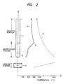
- Fig. 2 illustrates the circumstances of the temperature variations of the reaction gas (reformed gas) and the combustion gas within the reformer in the foregoing embodiment.
- the axis of abscissas represents the temperature
- the axis of ordinates represents the position of the reformer in the vertical direction thereof. That is, numeral 14 on the axis of ordinates indicates the position of the combustion catalyst layer constituting the heating source, and numeral 1 indicates the position of the reformer tube.
- a curve a in the graph indicates the variation of the temperature of the reaction gas rising in the reformer tube 1
- a curve b indicates the variation of the temperature of the combustion gas rising in the reformer.
- the present invention produces the effect that, owing to the liquid raw material, the reformer tubes are protected from any damage attributed to excess heating.
- the present invention is well suited for heating the reaction portion which contains a catalyst having a heat-resisting point of about 350 -400 °C, such as the reforming catalyst for methanol, and the activity of the catalyst can be prevented from lowering.
- the vaporization portion and the reaction portion are continuously arranged within the reformer tube 1. This brings forth the effect that the vaporization portion and the reaction portion disposed separately from each other in the prior art can be intergrated to reduce the size of the whole apparatus. Also, the heat loss can be diminished.
- the fuel which is supplied to the heater portion 33 there is used exhaust gas from a pressure swing adsorption (PSA) device in a hydrogen production unit, auxiliary fuel externally supplied, or the like.
- PSA pressure swing adsorption
Landscapes
- Chemical & Material Sciences (AREA)
- Chemical Kinetics & Catalysis (AREA)
- Organic Chemistry (AREA)
- Health & Medical Sciences (AREA)
- General Health & Medical Sciences (AREA)
- Engineering & Computer Science (AREA)
- Combustion & Propulsion (AREA)
- Inorganic Chemistry (AREA)
- Hydrogen, Water And Hydrids (AREA)
- Feeding And Controlling Fuel (AREA)
Claims (9)
- Reformiervorrichtung mit Reformierrohren (1) von denen jedes einen Reaktionsabschnitt (31), der mit einem Reformierkatalysator (11) zum Reformieren eines Rohmaterials gefüllt ist, einen Verdampfungsabschnitt (2), der zum Verdampfen des Rohmaterials dient und der unter dem Reaktionsabschnitt (31) in jedem Reformierrohr (1) ausgebildet ist, eine Wärmequelle (33), die zum Erwärmen der Verdampfungsabschnitte (2) und der Reaktionsabschnitte (31) von außerhalb der Reformierrohre (1) dient, Einrichtungen (21, 5, 3) zum Beschikken der Verdampfungsabschnitte (2) mit dem Rohmaterial in einem flüssigen Zustand und Fördereinrichtungen (10, 22) zum externen Zuführen eines Gases aufweist, das durch Hindurchführen durch die Reaktionsabschnitte (31) reformiert ist.
- Reformiervorrichtung nach Anspruch 1, bei welcher der Reaktionsabschnitt (31), welcher mit dem Reformierkatalysator (11) gefüllt ist, an einem oberen Teil in dem Reformierrohr (1) vorgesehen ist, und der Verdampfungsabschnitt (2) für das Rohmaterial unter dem Reaktionsabschnitt (31) in dem Reformierrohr (1) ausgebildet ist.
- Reformiervorrichtung nach Anspruch 1 oder 2, bei welcher Jedes Reformierrohr (1) einen Doppelrohraufbau hat, bei welchem der Verdampfungsabschnitt (2) an einem unteren Endteil des Reformierrohrs (1) ausgebildet ist, und das Rohmaterial dem Verdampfungsabschnitt (2) durch Führen innerhalb eines Innenrohres (3) des Doppelrohres zugeführt wird.
- Reformiervorrichtung nach Anspruch 3, bei welcher der Reaktionsabschnitt (31), der mit dem Katalysator (11) gefüllt ist, zwischen einem Außenrohr und dem Innenrohr (3) des Reformierrohrs (1) vorgesehen ist, der Verdampfungsabschnitt (2) unter dem Reaktionsabschnitt (31) vorgesehen ist und eine Schicht eines Packungsmaterials (12) an einem oberen Teil in dem Verdampfungsabschnitt (2) vorgesehen ist.
- Reformiervorrichtung nach einem der Ansprüche 1 bis 4, bei welchem das Rohmaterial ein Alkohol ist.
- Reformiervorrichtung nach Anspruch 5, bei welchem der Reformierkatalysator (11) eine Mischung eines KupferZink-Systems ist, das auf einem Aluminiumoxydträger getragen wird.
- Reformiervorrichtung nach einem der Ansprüche 4 bis 6, bei welchem das in dem oberen Teil des Verdampfungsabschnitts (2) gepackte Material (12) Aluminiumoxydkugeln oder Keramikkugeln sind.
- Reformiervorrichtung nach einem der Ansprüche 1 bis 7, bei welchem die Reformierrohre (1) in einem Mantel (4) angeordnet sind, ein Raum zwischen dem Mantel (4) und den Reformierrohren (1) mit einem WärmeübertragungsPackungsmaterial (13) gefüllt ist und der Heizabschnitt (33) unter den Reformierrohren (1) in dem Mantel (4) angeordnet ist, wobei in dem Heizabschnitt (33) Brennstoff verbrannt wird, um ein Verbrennungsgas zu erzeugen, wodurch die Verdampfungsabschnitte (2) an den unteren Teilen der Reformierrohre (1) und die Reaktionsabschnitte (31) an den oberen Teilen der Reformierrohre (1) von außerhalb der Reformierrohre (1) durch das Verbrennungsgas erwärmt werden.
- Reformiervorrichtung nach Anspruch 8, bei welcher der Heizabschnitt (33) eine Verbrennungskatalysatorschicht (14) aufweist, die Brennstoff und Luft infolge katalytischer Verbrennung verbrennt.
Applications Claiming Priority (2)
| Application Number | Priority Date | Filing Date | Title |
|---|---|---|---|
| JP10094886A JPS62260701A (ja) | 1986-05-02 | 1986-05-02 | 原料改質装置 |
| JP100948/86 | 1986-05-02 |
Publications (3)
| Publication Number | Publication Date |
|---|---|
| EP0247384A2 EP0247384A2 (de) | 1987-12-02 |
| EP0247384A3 EP0247384A3 (en) | 1988-09-14 |
| EP0247384B1 true EP0247384B1 (de) | 1991-02-20 |
Family
ID=14287571
Family Applications (1)
| Application Number | Title | Priority Date | Filing Date |
|---|---|---|---|
| EP19870106324 Expired EP0247384B1 (de) | 1986-05-02 | 1987-04-30 | Reformieranlage |
Country Status (3)
| Country | Link |
|---|---|
| EP (1) | EP0247384B1 (de) |
| JP (1) | JPS62260701A (de) |
| DE (1) | DE3768050D1 (de) |
Cited By (1)
| Publication number | Priority date | Publication date | Assignee | Title |
|---|---|---|---|---|
| TWI475176B (de) * | 2012-12-22 | 2015-03-01 |
Families Citing this family (12)
| Publication number | Priority date | Publication date | Assignee | Title |
|---|---|---|---|---|
| AU661877B2 (en) * | 1990-04-03 | 1995-08-10 | Standard Oil Company, The | Endothermic reaction apparatus |
| US5567398A (en) * | 1990-04-03 | 1996-10-22 | The Standard Oil Company | Endothermic reaction apparatus and method |
| US6153152A (en) * | 1990-04-03 | 2000-11-28 | The Standard Oil Company | Endothermic reaction apparatus and method |
| US6096106A (en) * | 1990-04-03 | 2000-08-01 | The Standard Oil Company | Endothermic reaction apparatus |
| FR2661902A1 (fr) * | 1990-05-09 | 1991-11-15 | Air Liquide | Procede et installation de production d'hydrogene a partir de methanol. |
| US6929785B2 (en) * | 2001-02-13 | 2005-08-16 | Delphi Technologies, Inc. | Method and apparatus for preheating of a fuel cell micro-reformer |
| US7063982B1 (en) * | 2002-03-12 | 2006-06-20 | Uop Llc | Process of vaporizing and reacting a liquid feed |
| EP1787951B1 (de) * | 2004-07-12 | 2015-04-08 | Sumitomo Seika Chemicals Co., Ltd. | Wasserstoffproduktionssystem und reformiervorrichtung |
| US7306770B2 (en) * | 2004-09-15 | 2007-12-11 | O.I. Corporation | High temperature combustion tube |
| JP4833597B2 (ja) * | 2005-07-05 | 2011-12-07 | 株式会社豊田中央研究所 | 水素供給装置 |
| US7939051B2 (en) | 2006-05-23 | 2011-05-10 | Idatech, Llc | Hydrogen-producing fuel processing assemblies, heating assemblies, and methods of operating the same |
| EP2812278B1 (de) * | 2012-02-06 | 2023-04-19 | Helbio Societé Anonyme Hydrogen and Energy Production Systems | Wärmeintegrierte reformer mit katalytischer verbrennung zur wasserstofferzeugung |
Family Cites Families (6)
| Publication number | Priority date | Publication date | Assignee | Title |
|---|---|---|---|---|
| US3541729A (en) * | 1968-05-09 | 1970-11-24 | Gen Electric | Compact reactor-boiler combination |
| CA1095696A (en) * | 1976-12-22 | 1981-02-17 | Richard F. Buswell | Catalytic reaction apparatus |
| JPS5423683A (en) * | 1977-07-22 | 1979-02-22 | Satoogoosee Kk | Manufacture of stopper piece |
| JPS58135104A (ja) * | 1982-02-03 | 1983-08-11 | Nissan Motor Co Ltd | エンジンのアルコ−ル改質装置 |
| EP0206608B1 (de) * | 1985-06-10 | 1993-09-08 | United States Department Of Energy | Brennstoffzelle mit integriertem Wasserdampfumformer |
| JPS62138305A (ja) * | 1985-12-10 | 1987-06-22 | Yamaha Motor Co Ltd | 燃料電池の燃料改質装置 |
-
1986
- 1986-05-02 JP JP10094886A patent/JPS62260701A/ja active Pending
-
1987
- 1987-04-30 DE DE8787106324T patent/DE3768050D1/de not_active Expired - Lifetime
- 1987-04-30 EP EP19870106324 patent/EP0247384B1/de not_active Expired
Cited By (1)
| Publication number | Priority date | Publication date | Assignee | Title |
|---|---|---|---|---|
| TWI475176B (de) * | 2012-12-22 | 2015-03-01 |
Also Published As
| Publication number | Publication date |
|---|---|
| EP0247384A2 (de) | 1987-12-02 |
| DE3768050D1 (de) | 1991-03-28 |
| EP0247384A3 (en) | 1988-09-14 |
| JPS62260701A (ja) | 1987-11-13 |
Similar Documents
| Publication | Publication Date | Title |
|---|---|---|
| US6497856B1 (en) | System for hydrogen generation through steam reforming of hydrocarbons and integrated chemical reactor for hydrogen production from hydrocarbons | |
| KR100858834B1 (ko) | 컴팩트형 증기 개질기 | |
| US6932958B2 (en) | Simplified three-stage fuel processor | |
| EP0247384B1 (de) | Reformieranlage | |
| JP4857258B2 (ja) | コンパクト蒸気改質装置 | |
| US4861347A (en) | Compact chemical reaction vessel | |
| CA2413388C (en) | Improved system for hydrogen generation through steam reforming of hydrocarbons and integrated chemical reactor for hydrogen production from hydrocarbons | |
| JP3075757B2 (ja) | 吸熱反応装置 | |
| US8617266B2 (en) | Hydrogen generating apparatus using steam reforming reaction | |
| US20070000173A1 (en) | Compact reforming reactor | |
| JP4504016B2 (ja) | 低パワーレンジにおいてガス状炭化水素から水素を生成するための高効率かつコンパクトなリフォーマ・ユニット | |
| US5156821A (en) | Reactor for reforming hydrocarbon | |
| JP2004149403A (ja) | 水素発生装置及び燃料電池発電システム | |
| KR970704252A (ko) | 연료 셀 발전소 노 | |
| JP4664767B2 (ja) | 改質器 | |
| KR20030004325A (ko) | 증기 개질 장치 | |
| JPH0335241B2 (de) | ||
| JP2733845B2 (ja) | 燃料電池用改質装置 | |
| JPS63248702A (ja) | 燃料改質装置 | |
| JP2700248B2 (ja) | 燃料改質装置の加熱装置 | |
| CA2354927A1 (en) | Fuel process and apparatus and control system | |
| JPH08270887A (ja) | 断熱設備及びこれを用いた燃料改質器 | |
| JPS6391421A (ja) | 高炉ガスを燃料とする専焼ボイラ−の操業方法 | |
| JPS62108704A (ja) | 燃料電池用の燃料改質装置 | |
| JPS6274991A (ja) | 燃料改質装置 |
Legal Events
| Date | Code | Title | Description |
|---|---|---|---|
| PUAI | Public reference made under article 153(3) epc to a published international application that has entered the european phase |
Free format text: ORIGINAL CODE: 0009012 |
|
| 17P | Request for examination filed |
Effective date: 19870430 |
|
| AK | Designated contracting states |
Kind code of ref document: A2 Designated state(s): DE FR GB |
|
| PUAL | Search report despatched |
Free format text: ORIGINAL CODE: 0009013 |
|
| AK | Designated contracting states |
Kind code of ref document: A3 Designated state(s): DE FR GB |
|
| 17Q | First examination report despatched |
Effective date: 19891006 |
|
| GRAA | (expected) grant |
Free format text: ORIGINAL CODE: 0009210 |
|
| AK | Designated contracting states |
Kind code of ref document: B1 Designated state(s): DE FR GB |
|
| REF | Corresponds to: |
Ref document number: 3768050 Country of ref document: DE Date of ref document: 19910328 |
|
| ET | Fr: translation filed | ||
| PLBE | No opposition filed within time limit |
Free format text: ORIGINAL CODE: 0009261 |
|
| STAA | Information on the status of an ep patent application or granted ep patent |
Free format text: STATUS: NO OPPOSITION FILED WITHIN TIME LIMIT |
|
| 26N | No opposition filed | ||
| PGFP | Annual fee paid to national office [announced via postgrant information from national office to epo] |
Ref country code: DE Payment date: 19970625 Year of fee payment: 11 |
|
| PGFP | Annual fee paid to national office [announced via postgrant information from national office to epo] |
Ref country code: FR Payment date: 19980415 Year of fee payment: 12 |
|
| PGFP | Annual fee paid to national office [announced via postgrant information from national office to epo] |
Ref country code: GB Payment date: 19980420 Year of fee payment: 12 |
|
| PG25 | Lapsed in a contracting state [announced via postgrant information from national office to epo] |
Ref country code: DE Free format text: LAPSE BECAUSE OF NON-PAYMENT OF DUE FEES Effective date: 19990202 |
|
| PG25 | Lapsed in a contracting state [announced via postgrant information from national office to epo] |
Ref country code: GB Free format text: LAPSE BECAUSE OF NON-PAYMENT OF DUE FEES Effective date: 19990430 |
|
| GBPC | Gb: european patent ceased through non-payment of renewal fee |
Effective date: 19990430 |
|
| PG25 | Lapsed in a contracting state [announced via postgrant information from national office to epo] |
Ref country code: FR Free format text: LAPSE BECAUSE OF NON-PAYMENT OF DUE FEES Effective date: 19991231 |
|
| REG | Reference to a national code |
Ref country code: FR Ref legal event code: ST |