EP0920997B1 - Liquid discharge head, method for manufacturing such head, head cartridge and liquid discharging apparatus - Google Patents
Liquid discharge head, method for manufacturing such head, head cartridge and liquid discharging apparatus Download PDFInfo
- Publication number
- EP0920997B1 EP0920997B1 EP98123170A EP98123170A EP0920997B1 EP 0920997 B1 EP0920997 B1 EP 0920997B1 EP 98123170 A EP98123170 A EP 98123170A EP 98123170 A EP98123170 A EP 98123170A EP 0920997 B1 EP0920997 B1 EP 0920997B1
- Authority
- EP
- European Patent Office
- Prior art keywords
- liquid
- separation diaphragm
- movable separation
- diaphragm
- bubble
- Prior art date
- Legal status (The legal status is an assumption and is not a legal conclusion. Google has not performed a legal analysis and makes no representation as to the accuracy of the status listed.)
- Expired - Lifetime
Links
- 239000007788 liquid Substances 0.000 title claims description 840
- 238000007599 discharging Methods 0.000 title claims description 141
- 238000000034 method Methods 0.000 title claims description 81
- 238000004519 manufacturing process Methods 0.000 title claims description 55
- 238000000926 separation method Methods 0.000 claims description 315
- 239000000758 substrate Substances 0.000 claims description 86
- 238000005304 joining Methods 0.000 claims description 73
- 230000005587 bubbling Effects 0.000 description 115
- 239000010408 film Substances 0.000 description 86
- 238000011144 upstream manufacturing Methods 0.000 description 70
- 238000006073 displacement reaction Methods 0.000 description 38
- 239000000463 material Substances 0.000 description 38
- 238000005530 etching Methods 0.000 description 24
- 230000001105 regulatory effect Effects 0.000 description 23
- 238000009835 boiling Methods 0.000 description 22
- 230000008569 process Effects 0.000 description 18
- 229920001296 polysiloxane Polymers 0.000 description 17
- 230000004075 alteration Effects 0.000 description 15
- 230000000694 effects Effects 0.000 description 15
- VYPSYNLAJGMNEJ-UHFFFAOYSA-N Silicium dioxide Chemical compound O=[Si]=O VYPSYNLAJGMNEJ-UHFFFAOYSA-N 0.000 description 14
- 239000006185 dispersion Substances 0.000 description 14
- 239000005360 phosphosilicate glass Substances 0.000 description 13
- 239000000203 mixture Substances 0.000 description 12
- 238000005229 chemical vapour deposition Methods 0.000 description 11
- 238000000206 photolithography Methods 0.000 description 11
- XUIMIQQOPSSXEZ-UHFFFAOYSA-N Silicon Chemical compound [Si] XUIMIQQOPSSXEZ-UHFFFAOYSA-N 0.000 description 10
- 238000010276 construction Methods 0.000 description 10
- 239000000126 substance Substances 0.000 description 10
- 239000010409 thin film Substances 0.000 description 10
- LFQSCWFLJHTTHZ-UHFFFAOYSA-N Ethanol Chemical compound CCO LFQSCWFLJHTTHZ-UHFFFAOYSA-N 0.000 description 9
- 230000015572 biosynthetic process Effects 0.000 description 9
- 230000008602 contraction Effects 0.000 description 9
- 229910052710 silicon Inorganic materials 0.000 description 9
- 239000010703 silicon Substances 0.000 description 9
- 238000000151 deposition Methods 0.000 description 8
- 238000010438 heat treatment Methods 0.000 description 8
- 230000008018 melting Effects 0.000 description 8
- 238000002844 melting Methods 0.000 description 8
- 230000009467 reduction Effects 0.000 description 8
- 238000009825 accumulation Methods 0.000 description 7
- 229910052681 coesite Inorganic materials 0.000 description 7
- 229910052906 cristobalite Inorganic materials 0.000 description 7
- 238000006116 polymerization reaction Methods 0.000 description 7
- 239000000377 silicon dioxide Substances 0.000 description 7
- 239000002904 solvent Substances 0.000 description 7
- 229910052682 stishovite Inorganic materials 0.000 description 7
- 238000012360 testing method Methods 0.000 description 7
- 229910052905 tridymite Inorganic materials 0.000 description 7
- XLYOFNOQVPJJNP-UHFFFAOYSA-N water Substances O XLYOFNOQVPJJNP-UHFFFAOYSA-N 0.000 description 7
- 230000008021 deposition Effects 0.000 description 6
- 239000007789 gas Substances 0.000 description 6
- 229910010272 inorganic material Inorganic materials 0.000 description 6
- 239000011147 inorganic material Substances 0.000 description 6
- 230000005499 meniscus Effects 0.000 description 6
- 238000011084 recovery Methods 0.000 description 6
- WGTYBPLFGIVFAS-UHFFFAOYSA-M tetramethylammonium hydroxide Chemical compound [OH-].C[N+](C)(C)C WGTYBPLFGIVFAS-UHFFFAOYSA-M 0.000 description 6
- KFZMGEQAYNKOFK-UHFFFAOYSA-N Isopropanol Chemical compound CC(C)O KFZMGEQAYNKOFK-UHFFFAOYSA-N 0.000 description 5
- 239000004411 aluminium Substances 0.000 description 5
- 229910052782 aluminium Inorganic materials 0.000 description 5
- XAGFODPZIPBFFR-UHFFFAOYSA-N aluminium Chemical compound [Al] XAGFODPZIPBFFR-UHFFFAOYSA-N 0.000 description 5
- 230000008859 change Effects 0.000 description 5
- 238000006243 chemical reaction Methods 0.000 description 5
- 238000009413 insulation Methods 0.000 description 5
- 230000000644 propagated effect Effects 0.000 description 5
- 230000002159 abnormal effect Effects 0.000 description 4
- 239000003513 alkali Substances 0.000 description 4
- 239000012535 impurity Substances 0.000 description 4
- 238000005268 plasma chemical vapour deposition Methods 0.000 description 4
- ZWEHNKRNPOVVGH-UHFFFAOYSA-N 2-Butanone Chemical compound CCC(C)=O ZWEHNKRNPOVVGH-UHFFFAOYSA-N 0.000 description 3
- CSCPPACGZOOCGX-UHFFFAOYSA-N Acetone Chemical compound CC(C)=O CSCPPACGZOOCGX-UHFFFAOYSA-N 0.000 description 3
- QGZKDVFQNNGYKY-UHFFFAOYSA-N Ammonia Chemical compound N QGZKDVFQNNGYKY-UHFFFAOYSA-N 0.000 description 3
- XEKOWRVHYACXOJ-UHFFFAOYSA-N Ethyl acetate Chemical compound CCOC(C)=O XEKOWRVHYACXOJ-UHFFFAOYSA-N 0.000 description 3
- PEDCQBHIVMGVHV-UHFFFAOYSA-N Glycerine Chemical compound OCC(O)CO PEDCQBHIVMGVHV-UHFFFAOYSA-N 0.000 description 3
- OKKJLVBELUTLKV-UHFFFAOYSA-N Methanol Chemical compound OC OKKJLVBELUTLKV-UHFFFAOYSA-N 0.000 description 3
- IMNFDUFMRHMDMM-UHFFFAOYSA-N N-Heptane Chemical compound CCCCCCC IMNFDUFMRHMDMM-UHFFFAOYSA-N 0.000 description 3
- BLRPTPMANUNPDV-UHFFFAOYSA-N Silane Chemical compound [SiH4] BLRPTPMANUNPDV-UHFFFAOYSA-N 0.000 description 3
- YXFVVABEGXRONW-UHFFFAOYSA-N Toluene Chemical compound CC1=CC=CC=C1 YXFVVABEGXRONW-UHFFFAOYSA-N 0.000 description 3
- 238000005299 abrasion Methods 0.000 description 3
- 239000000539 dimer Substances 0.000 description 3
- 239000011368 organic material Substances 0.000 description 3
- 230000001902 propagating effect Effects 0.000 description 3
- 239000004065 semiconductor Substances 0.000 description 3
- 230000035882 stress Effects 0.000 description 3
- -1 thread Substances 0.000 description 3
- XKRFYHLGVUSROY-UHFFFAOYSA-N Argon Chemical compound [Ar] XKRFYHLGVUSROY-UHFFFAOYSA-N 0.000 description 2
- YMWUJEATGCHHMB-UHFFFAOYSA-N Dichloromethane Chemical compound ClCCl YMWUJEATGCHHMB-UHFFFAOYSA-N 0.000 description 2
- RTZKZFJDLAIYFH-UHFFFAOYSA-N Diethyl ether Chemical compound CCOCC RTZKZFJDLAIYFH-UHFFFAOYSA-N 0.000 description 2
- 229910052581 Si3N4 Inorganic materials 0.000 description 2
- 230000005856 abnormality Effects 0.000 description 2
- 239000000853 adhesive Substances 0.000 description 2
- 230000001070 adhesive effect Effects 0.000 description 2
- 238000013459 approach Methods 0.000 description 2
- 230000007797 corrosion Effects 0.000 description 2
- 238000005260 corrosion Methods 0.000 description 2
- 238000005520 cutting process Methods 0.000 description 2
- 238000009792 diffusion process Methods 0.000 description 2
- 230000008034 disappearance Effects 0.000 description 2
- 230000007613 environmental effect Effects 0.000 description 2
- 238000010884 ion-beam technique Methods 0.000 description 2
- 150000002500 ions Chemical class 0.000 description 2
- 229910052751 metal Inorganic materials 0.000 description 2
- 239000002184 metal Substances 0.000 description 2
- 238000002156 mixing Methods 0.000 description 2
- TVMXDCGIABBOFY-UHFFFAOYSA-N octane Chemical compound CCCCCCCC TVMXDCGIABBOFY-UHFFFAOYSA-N 0.000 description 2
- 230000003647 oxidation Effects 0.000 description 2
- 238000007254 oxidation reaction Methods 0.000 description 2
- 239000012071 phase Substances 0.000 description 2
- BDERNNFJNOPAEC-UHFFFAOYSA-N propan-1-ol Chemical compound CCCO BDERNNFJNOPAEC-UHFFFAOYSA-N 0.000 description 2
- 238000001454 recorded image Methods 0.000 description 2
- 239000011347 resin Substances 0.000 description 2
- 229920005989 resin Polymers 0.000 description 2
- NTHWMYGWWRZVTN-UHFFFAOYSA-N sodium silicate Chemical compound [Na+].[Na+].[O-][Si]([O-])=O NTHWMYGWWRZVTN-UHFFFAOYSA-N 0.000 description 2
- 239000012808 vapor phase Substances 0.000 description 2
- 238000001947 vapour-phase growth Methods 0.000 description 2
- HZAXFHJVJLSVMW-UHFFFAOYSA-N 2-Aminoethan-1-ol Chemical compound NCCO HZAXFHJVJLSVMW-UHFFFAOYSA-N 0.000 description 1
- MKALOVJHPRAZRE-UHFFFAOYSA-N 5-phenylpenta-2,4-dienoic acid;prop-2-enoic acid Chemical compound OC(=O)C=C.OC(=O)C=CC=CC1=CC=CC=C1 MKALOVJHPRAZRE-UHFFFAOYSA-N 0.000 description 1
- 229910000838 Al alloy Inorganic materials 0.000 description 1
- 229910018125 Al-Si Inorganic materials 0.000 description 1
- 229910018182 Al—Cu Inorganic materials 0.000 description 1
- 229910018520 Al—Si Inorganic materials 0.000 description 1
- IJGRMHOSHXDMSA-UHFFFAOYSA-N Atomic nitrogen Chemical compound N#N IJGRMHOSHXDMSA-UHFFFAOYSA-N 0.000 description 1
- XDTMQSROBMDMFD-UHFFFAOYSA-N Cyclohexane Chemical compound C1CCCCC1 XDTMQSROBMDMFD-UHFFFAOYSA-N 0.000 description 1
- CTQNGGLPUBDAKN-UHFFFAOYSA-N O-Xylene Chemical compound CC1=CC=CC=C1C CTQNGGLPUBDAKN-UHFFFAOYSA-N 0.000 description 1
- 239000002202 Polyethylene glycol Substances 0.000 description 1
- 239000004642 Polyimide Substances 0.000 description 1
- XBDQKXXYIPTUBI-UHFFFAOYSA-M Propionate Chemical compound CCC([O-])=O XBDQKXXYIPTUBI-UHFFFAOYSA-M 0.000 description 1
- 229910007264 Si2H6 Inorganic materials 0.000 description 1
- 239000004115 Sodium Silicate Substances 0.000 description 1
- 238000010521 absorption reaction Methods 0.000 description 1
- KXKVLQRXCPHEJC-UHFFFAOYSA-N acetic acid trimethyl ester Natural products COC(C)=O KXKVLQRXCPHEJC-UHFFFAOYSA-N 0.000 description 1
- 239000002253 acid Substances 0.000 description 1
- 230000009471 action Effects 0.000 description 1
- 229910021529 ammonia Inorganic materials 0.000 description 1
- 229910052786 argon Inorganic materials 0.000 description 1
- 239000002585 base Substances 0.000 description 1
- 230000008901 benefit Effects 0.000 description 1
- 239000006229 carbon black Substances 0.000 description 1
- 239000000919 ceramic Substances 0.000 description 1
- 239000011248 coating agent Substances 0.000 description 1
- 238000000576 coating method Methods 0.000 description 1
- 238000004891 communication Methods 0.000 description 1
- 239000002131 composite material Substances 0.000 description 1
- 239000012141 concentrate Substances 0.000 description 1
- 239000004020 conductor Substances 0.000 description 1
- 229920001577 copolymer Polymers 0.000 description 1
- 239000013078 crystal Substances 0.000 description 1
- 230000006378 damage Effects 0.000 description 1
- 238000000354 decomposition reaction Methods 0.000 description 1
- 230000003247 decreasing effect Effects 0.000 description 1
- 230000001419 dependent effect Effects 0.000 description 1
- 238000001514 detection method Methods 0.000 description 1
- 230000006866 deterioration Effects 0.000 description 1
- 238000011161 development Methods 0.000 description 1
- 230000018109 developmental process Effects 0.000 description 1
- PZPGRFITIJYNEJ-UHFFFAOYSA-N disilane Chemical compound [SiH3][SiH3] PZPGRFITIJYNEJ-UHFFFAOYSA-N 0.000 description 1
- 229940079593 drug Drugs 0.000 description 1
- 239000003814 drug Substances 0.000 description 1
- 238000001312 dry etching Methods 0.000 description 1
- 229920001971 elastomer Polymers 0.000 description 1
- 239000004744 fabric Substances 0.000 description 1
- 239000000835 fiber Substances 0.000 description 1
- 238000010304 firing Methods 0.000 description 1
- 239000011521 glass Substances 0.000 description 1
- 230000006872 improvement Effects 0.000 description 1
- 239000000543 intermediate Substances 0.000 description 1
- 239000010985 leather Substances 0.000 description 1
- 239000000178 monomer Substances 0.000 description 1
- 229910000069 nitrogen hydride Inorganic materials 0.000 description 1
- 239000003921 oil Substances 0.000 description 1
- 239000003960 organic solvent Substances 0.000 description 1
- 239000003973 paint Substances 0.000 description 1
- 239000002245 particle Substances 0.000 description 1
- 238000000059 patterning Methods 0.000 description 1
- 230000035515 penetration Effects 0.000 description 1
- 239000002304 perfume Substances 0.000 description 1
- 239000000049 pigment Substances 0.000 description 1
- 239000004033 plastic Substances 0.000 description 1
- 229920003023 plastic Polymers 0.000 description 1
- 238000005498 polishing Methods 0.000 description 1
- 238000007517 polishing process Methods 0.000 description 1
- 229910021420 polycrystalline silicon Inorganic materials 0.000 description 1
- 229920001223 polyethylene glycol Polymers 0.000 description 1
- 229940113115 polyethylene glycol 200 Drugs 0.000 description 1
- 229940057847 polyethylene glycol 600 Drugs 0.000 description 1
- 229920001721 polyimide Polymers 0.000 description 1
- 229920000642 polymer Polymers 0.000 description 1
- 239000004810 polytetrafluoroethylene Substances 0.000 description 1
- 229920001343 polytetrafluoroethylene Polymers 0.000 description 1
- 235000019353 potassium silicate Nutrition 0.000 description 1
- 230000002265 prevention Effects 0.000 description 1
- 238000012545 processing Methods 0.000 description 1
- 239000002994 raw material Substances 0.000 description 1
- 239000005871 repellent Substances 0.000 description 1
- 230000004044 response Effects 0.000 description 1
- 230000035939 shock Effects 0.000 description 1
- 229920002379 silicone rubber Polymers 0.000 description 1
- 239000004945 silicone rubber Substances 0.000 description 1
- 229910052911 sodium silicate Inorganic materials 0.000 description 1
- 239000007787 solid Substances 0.000 description 1
- 125000000446 sulfanediyl group Chemical group *S* 0.000 description 1
- 230000008646 thermal stress Effects 0.000 description 1
- 230000004304 visual acuity Effects 0.000 description 1
- 239000002023 wood Substances 0.000 description 1
- IGELFKKMDLGCJO-UHFFFAOYSA-N xenon difluoride Chemical compound F[Xe]F IGELFKKMDLGCJO-UHFFFAOYSA-N 0.000 description 1
- 239000008096 xylene Substances 0.000 description 1
Images


Classifications
-
- B—PERFORMING OPERATIONS; TRANSPORTING
- B23—MACHINE TOOLS; METAL-WORKING NOT OTHERWISE PROVIDED FOR
- B23K—SOLDERING OR UNSOLDERING; WELDING; CLADDING OR PLATING BY SOLDERING OR WELDING; CUTTING BY APPLYING HEAT LOCALLY, e.g. FLAME CUTTING; WORKING BY LASER BEAM
- B23K26/00—Working by laser beam, e.g. welding, cutting or boring
- B23K26/18—Working by laser beam, e.g. welding, cutting or boring using absorbing layers on the workpiece, e.g. for marking or protecting purposes
-
- B—PERFORMING OPERATIONS; TRANSPORTING
- B41—PRINTING; LINING MACHINES; TYPEWRITERS; STAMPS
- B41J—TYPEWRITERS; SELECTIVE PRINTING MECHANISMS, i.e. MECHANISMS PRINTING OTHERWISE THAN FROM A FORME; CORRECTION OF TYPOGRAPHICAL ERRORS
- B41J2/00—Typewriters or selective printing mechanisms characterised by the printing or marking process for which they are designed
-
- B—PERFORMING OPERATIONS; TRANSPORTING
- B23—MACHINE TOOLS; METAL-WORKING NOT OTHERWISE PROVIDED FOR
- B23K—SOLDERING OR UNSOLDERING; WELDING; CLADDING OR PLATING BY SOLDERING OR WELDING; CUTTING BY APPLYING HEAT LOCALLY, e.g. FLAME CUTTING; WORKING BY LASER BEAM
- B23K26/00—Working by laser beam, e.g. welding, cutting or boring
- B23K26/02—Positioning or observing the workpiece, e.g. with respect to the point of impact; Aligning, aiming or focusing the laser beam
- B23K26/06—Shaping the laser beam, e.g. by masks or multi-focusing
- B23K26/064—Shaping the laser beam, e.g. by masks or multi-focusing by means of optical elements, e.g. lenses, mirrors or prisms
- B23K26/066—Shaping the laser beam, e.g. by masks or multi-focusing by means of optical elements, e.g. lenses, mirrors or prisms by using masks
- B23K26/0661—Shaping the laser beam, e.g. by masks or multi-focusing by means of optical elements, e.g. lenses, mirrors or prisms by using masks disposed on the workpiece
-
- B—PERFORMING OPERATIONS; TRANSPORTING
- B23—MACHINE TOOLS; METAL-WORKING NOT OTHERWISE PROVIDED FOR
- B23K—SOLDERING OR UNSOLDERING; WELDING; CLADDING OR PLATING BY SOLDERING OR WELDING; CUTTING BY APPLYING HEAT LOCALLY, e.g. FLAME CUTTING; WORKING BY LASER BEAM
- B23K26/00—Working by laser beam, e.g. welding, cutting or boring
- B23K26/36—Removing material
- B23K26/38—Removing material by boring or cutting
- B23K26/382—Removing material by boring or cutting by boring
- B23K26/389—Removing material by boring or cutting by boring of fluid openings, e.g. nozzles, jets
-
- B—PERFORMING OPERATIONS; TRANSPORTING
- B23—MACHINE TOOLS; METAL-WORKING NOT OTHERWISE PROVIDED FOR
- B23K—SOLDERING OR UNSOLDERING; WELDING; CLADDING OR PLATING BY SOLDERING OR WELDING; CUTTING BY APPLYING HEAT LOCALLY, e.g. FLAME CUTTING; WORKING BY LASER BEAM
- B23K26/00—Working by laser beam, e.g. welding, cutting or boring
- B23K26/36—Removing material
- B23K26/40—Removing material taking account of the properties of the material involved
-
- B—PERFORMING OPERATIONS; TRANSPORTING
- B41—PRINTING; LINING MACHINES; TYPEWRITERS; STAMPS
- B41J—TYPEWRITERS; SELECTIVE PRINTING MECHANISMS, i.e. MECHANISMS PRINTING OTHERWISE THAN FROM A FORME; CORRECTION OF TYPOGRAPHICAL ERRORS
- B41J2/00—Typewriters or selective printing mechanisms characterised by the printing or marking process for which they are designed
- B41J2/005—Typewriters or selective printing mechanisms characterised by the printing or marking process for which they are designed characterised by bringing liquid or particles selectively into contact with a printing material
- B41J2/01—Ink jet
- B41J2/135—Nozzles
- B41J2/14—Structure thereof only for on-demand ink jet heads
- B41J2/14016—Structure of bubble jet print heads
- B41J2/14032—Structure of the pressure chamber
- B41J2/1404—Geometrical characteristics
-
- B—PERFORMING OPERATIONS; TRANSPORTING
- B41—PRINTING; LINING MACHINES; TYPEWRITERS; STAMPS
- B41J—TYPEWRITERS; SELECTIVE PRINTING MECHANISMS, i.e. MECHANISMS PRINTING OTHERWISE THAN FROM A FORME; CORRECTION OF TYPOGRAPHICAL ERRORS
- B41J2/00—Typewriters or selective printing mechanisms characterised by the printing or marking process for which they are designed
- B41J2/005—Typewriters or selective printing mechanisms characterised by the printing or marking process for which they are designed characterised by bringing liquid or particles selectively into contact with a printing material
- B41J2/01—Ink jet
- B41J2/135—Nozzles
- B41J2/14—Structure thereof only for on-demand ink jet heads
- B41J2/14016—Structure of bubble jet print heads
- B41J2/14032—Structure of the pressure chamber
- B41J2/14048—Movable member in the chamber
-
- B—PERFORMING OPERATIONS; TRANSPORTING
- B41—PRINTING; LINING MACHINES; TYPEWRITERS; STAMPS
- B41J—TYPEWRITERS; SELECTIVE PRINTING MECHANISMS, i.e. MECHANISMS PRINTING OTHERWISE THAN FROM A FORME; CORRECTION OF TYPOGRAPHICAL ERRORS
- B41J2/00—Typewriters or selective printing mechanisms characterised by the printing or marking process for which they are designed
- B41J2/005—Typewriters or selective printing mechanisms characterised by the printing or marking process for which they are designed characterised by bringing liquid or particles selectively into contact with a printing material
- B41J2/01—Ink jet
- B41J2/135—Nozzles
- B41J2/14—Structure thereof only for on-demand ink jet heads
- B41J2/14016—Structure of bubble jet print heads
- B41J2/14032—Structure of the pressure chamber
- B41J2/14064—Heater chamber separated from ink chamber by a membrane
-
- B—PERFORMING OPERATIONS; TRANSPORTING
- B41—PRINTING; LINING MACHINES; TYPEWRITERS; STAMPS
- B41J—TYPEWRITERS; SELECTIVE PRINTING MECHANISMS, i.e. MECHANISMS PRINTING OTHERWISE THAN FROM A FORME; CORRECTION OF TYPOGRAPHICAL ERRORS
- B41J2/00—Typewriters or selective printing mechanisms characterised by the printing or marking process for which they are designed
- B41J2/005—Typewriters or selective printing mechanisms characterised by the printing or marking process for which they are designed characterised by bringing liquid or particles selectively into contact with a printing material
- B41J2/01—Ink jet
- B41J2/135—Nozzles
- B41J2/14—Structure thereof only for on-demand ink jet heads
- B41J2/14016—Structure of bubble jet print heads
- B41J2/14088—Structure of heating means
- B41J2/14112—Resistive element
- B41J2/14129—Layer structure
-
- B—PERFORMING OPERATIONS; TRANSPORTING
- B41—PRINTING; LINING MACHINES; TYPEWRITERS; STAMPS
- B41J—TYPEWRITERS; SELECTIVE PRINTING MECHANISMS, i.e. MECHANISMS PRINTING OTHERWISE THAN FROM A FORME; CORRECTION OF TYPOGRAPHICAL ERRORS
- B41J2/00—Typewriters or selective printing mechanisms characterised by the printing or marking process for which they are designed
- B41J2/005—Typewriters or selective printing mechanisms characterised by the printing or marking process for which they are designed characterised by bringing liquid or particles selectively into contact with a printing material
- B41J2/01—Ink jet
- B41J2/135—Nozzles
- B41J2/16—Production of nozzles
- B41J2/1601—Production of bubble jet print heads
- B41J2/1604—Production of bubble jet print heads of the edge shooter type
-
- B—PERFORMING OPERATIONS; TRANSPORTING
- B41—PRINTING; LINING MACHINES; TYPEWRITERS; STAMPS
- B41J—TYPEWRITERS; SELECTIVE PRINTING MECHANISMS, i.e. MECHANISMS PRINTING OTHERWISE THAN FROM A FORME; CORRECTION OF TYPOGRAPHICAL ERRORS
- B41J2/00—Typewriters or selective printing mechanisms characterised by the printing or marking process for which they are designed
- B41J2/005—Typewriters or selective printing mechanisms characterised by the printing or marking process for which they are designed characterised by bringing liquid or particles selectively into contact with a printing material
- B41J2/01—Ink jet
- B41J2/135—Nozzles
- B41J2/16—Production of nozzles
- B41J2/1621—Manufacturing processes
- B41J2/1623—Manufacturing processes bonding and adhesion
-
- B—PERFORMING OPERATIONS; TRANSPORTING
- B41—PRINTING; LINING MACHINES; TYPEWRITERS; STAMPS
- B41J—TYPEWRITERS; SELECTIVE PRINTING MECHANISMS, i.e. MECHANISMS PRINTING OTHERWISE THAN FROM A FORME; CORRECTION OF TYPOGRAPHICAL ERRORS
- B41J2/00—Typewriters or selective printing mechanisms characterised by the printing or marking process for which they are designed
- B41J2/005—Typewriters or selective printing mechanisms characterised by the printing or marking process for which they are designed characterised by bringing liquid or particles selectively into contact with a printing material
- B41J2/01—Ink jet
- B41J2/135—Nozzles
- B41J2/16—Production of nozzles
- B41J2/1621—Manufacturing processes
- B41J2/1626—Manufacturing processes etching
- B41J2/1628—Manufacturing processes etching dry etching
-
- B—PERFORMING OPERATIONS; TRANSPORTING
- B41—PRINTING; LINING MACHINES; TYPEWRITERS; STAMPS
- B41J—TYPEWRITERS; SELECTIVE PRINTING MECHANISMS, i.e. MECHANISMS PRINTING OTHERWISE THAN FROM A FORME; CORRECTION OF TYPOGRAPHICAL ERRORS
- B41J2/00—Typewriters or selective printing mechanisms characterised by the printing or marking process for which they are designed
- B41J2/005—Typewriters or selective printing mechanisms characterised by the printing or marking process for which they are designed characterised by bringing liquid or particles selectively into contact with a printing material
- B41J2/01—Ink jet
- B41J2/135—Nozzles
- B41J2/16—Production of nozzles
- B41J2/1621—Manufacturing processes
- B41J2/1626—Manufacturing processes etching
- B41J2/1629—Manufacturing processes etching wet etching
-
- B—PERFORMING OPERATIONS; TRANSPORTING
- B41—PRINTING; LINING MACHINES; TYPEWRITERS; STAMPS
- B41J—TYPEWRITERS; SELECTIVE PRINTING MECHANISMS, i.e. MECHANISMS PRINTING OTHERWISE THAN FROM A FORME; CORRECTION OF TYPOGRAPHICAL ERRORS
- B41J2/00—Typewriters or selective printing mechanisms characterised by the printing or marking process for which they are designed
- B41J2/005—Typewriters or selective printing mechanisms characterised by the printing or marking process for which they are designed characterised by bringing liquid or particles selectively into contact with a printing material
- B41J2/01—Ink jet
- B41J2/135—Nozzles
- B41J2/16—Production of nozzles
- B41J2/1621—Manufacturing processes
- B41J2/1631—Manufacturing processes photolithography
-
- B—PERFORMING OPERATIONS; TRANSPORTING
- B41—PRINTING; LINING MACHINES; TYPEWRITERS; STAMPS
- B41J—TYPEWRITERS; SELECTIVE PRINTING MECHANISMS, i.e. MECHANISMS PRINTING OTHERWISE THAN FROM A FORME; CORRECTION OF TYPOGRAPHICAL ERRORS
- B41J2/00—Typewriters or selective printing mechanisms characterised by the printing or marking process for which they are designed
- B41J2/005—Typewriters or selective printing mechanisms characterised by the printing or marking process for which they are designed characterised by bringing liquid or particles selectively into contact with a printing material
- B41J2/01—Ink jet
- B41J2/135—Nozzles
- B41J2/16—Production of nozzles
- B41J2/1621—Manufacturing processes
- B41J2/1632—Manufacturing processes machining
- B41J2/1634—Manufacturing processes machining laser machining
-
- B—PERFORMING OPERATIONS; TRANSPORTING
- B41—PRINTING; LINING MACHINES; TYPEWRITERS; STAMPS
- B41J—TYPEWRITERS; SELECTIVE PRINTING MECHANISMS, i.e. MECHANISMS PRINTING OTHERWISE THAN FROM A FORME; CORRECTION OF TYPOGRAPHICAL ERRORS
- B41J2/00—Typewriters or selective printing mechanisms characterised by the printing or marking process for which they are designed
- B41J2/005—Typewriters or selective printing mechanisms characterised by the printing or marking process for which they are designed characterised by bringing liquid or particles selectively into contact with a printing material
- B41J2/01—Ink jet
- B41J2/135—Nozzles
- B41J2/16—Production of nozzles
- B41J2/1621—Manufacturing processes
- B41J2/1635—Manufacturing processes dividing the wafer into individual chips
-
- B—PERFORMING OPERATIONS; TRANSPORTING
- B41—PRINTING; LINING MACHINES; TYPEWRITERS; STAMPS
- B41J—TYPEWRITERS; SELECTIVE PRINTING MECHANISMS, i.e. MECHANISMS PRINTING OTHERWISE THAN FROM A FORME; CORRECTION OF TYPOGRAPHICAL ERRORS
- B41J2/00—Typewriters or selective printing mechanisms characterised by the printing or marking process for which they are designed
- B41J2/005—Typewriters or selective printing mechanisms characterised by the printing or marking process for which they are designed characterised by bringing liquid or particles selectively into contact with a printing material
- B41J2/01—Ink jet
- B41J2/135—Nozzles
- B41J2/16—Production of nozzles
- B41J2/1621—Manufacturing processes
- B41J2/1637—Manufacturing processes molding
- B41J2/1639—Manufacturing processes molding sacrificial molding
-
- B—PERFORMING OPERATIONS; TRANSPORTING
- B41—PRINTING; LINING MACHINES; TYPEWRITERS; STAMPS
- B41J—TYPEWRITERS; SELECTIVE PRINTING MECHANISMS, i.e. MECHANISMS PRINTING OTHERWISE THAN FROM A FORME; CORRECTION OF TYPOGRAPHICAL ERRORS
- B41J2/00—Typewriters or selective printing mechanisms characterised by the printing or marking process for which they are designed
- B41J2/005—Typewriters or selective printing mechanisms characterised by the printing or marking process for which they are designed characterised by bringing liquid or particles selectively into contact with a printing material
- B41J2/01—Ink jet
- B41J2/135—Nozzles
- B41J2/16—Production of nozzles
- B41J2/1621—Manufacturing processes
- B41J2/164—Manufacturing processes thin film formation
- B41J2/1642—Manufacturing processes thin film formation thin film formation by CVD [chemical vapor deposition]
-
- B—PERFORMING OPERATIONS; TRANSPORTING
- B23—MACHINE TOOLS; METAL-WORKING NOT OTHERWISE PROVIDED FOR
- B23K—SOLDERING OR UNSOLDERING; WELDING; CLADDING OR PLATING BY SOLDERING OR WELDING; CUTTING BY APPLYING HEAT LOCALLY, e.g. FLAME CUTTING; WORKING BY LASER BEAM
- B23K2103/00—Materials to be soldered, welded or cut
- B23K2103/30—Organic material
- B23K2103/42—Plastics
-
- B—PERFORMING OPERATIONS; TRANSPORTING
- B23—MACHINE TOOLS; METAL-WORKING NOT OTHERWISE PROVIDED FOR
- B23K—SOLDERING OR UNSOLDERING; WELDING; CLADDING OR PLATING BY SOLDERING OR WELDING; CUTTING BY APPLYING HEAT LOCALLY, e.g. FLAME CUTTING; WORKING BY LASER BEAM
- B23K2103/00—Materials to be soldered, welded or cut
- B23K2103/50—Inorganic material, e.g. metals, not provided for in B23K2103/02 – B23K2103/26
- B23K2103/52—Ceramics
-
- B—PERFORMING OPERATIONS; TRANSPORTING
- B41—PRINTING; LINING MACHINES; TYPEWRITERS; STAMPS
- B41J—TYPEWRITERS; SELECTIVE PRINTING MECHANISMS, i.e. MECHANISMS PRINTING OTHERWISE THAN FROM A FORME; CORRECTION OF TYPOGRAPHICAL ERRORS
- B41J2202/00—Embodiments of or processes related to ink-jet or thermal heads
- B41J2202/01—Embodiments of or processes related to ink-jet heads
- B41J2202/03—Specific materials used
-
- B—PERFORMING OPERATIONS; TRANSPORTING
- B41—PRINTING; LINING MACHINES; TYPEWRITERS; STAMPS
- B41J—TYPEWRITERS; SELECTIVE PRINTING MECHANISMS, i.e. MECHANISMS PRINTING OTHERWISE THAN FROM A FORME; CORRECTION OF TYPOGRAPHICAL ERRORS
- B41J2202/00—Embodiments of or processes related to ink-jet or thermal heads
- B41J2202/01—Embodiments of or processes related to ink-jet heads
- B41J2202/13—Heads having an integrated circuit
Definitions
- the present invention relates to a method for manufacturing a liquid discharge head for discharging desired liquid by generating a bubble by acting thermal energy on the liquid, such a liquid discharge head, a head cartridge using such a liquid discharge head, and a liquid discharging apparatus.
- the present invention can be applied to an apparatus such as a printer, a copying machine, a facsimile having a communication system and a word processor having a printer portion for effecting recording with respect to a recording medium such as paper, thread, fibers, cloth, leather, metal, plastic, glass, wood or ceramics and the like, and an industrial recording apparatus combined with various processing devices in a composite manner.
- a printer such as a printer, a copying machine, a facsimile having a communication system and a word processor having a printer portion for effecting recording with respect to a recording medium such as paper, thread, fibers, cloth, leather, metal, plastic, glass, wood or ceramics and the like
- an industrial recording apparatus combined with various processing devices in a composite manner.
- recording means not only that an image such as a character or a figure is applied on a recording medium but also that an image such as a pattern having no meaning is applied to a recording medium.
- a recording apparatus using such a bubble jet recording method generally includes discharge ports for discharging the ink, ink passages communicated with the discharge ports, and heat generating bodies (electrothermal converting elements) as energy generating means disposed in the ink passages and adapted to discharge the ink, as disclosed in Japanese Patent Publication Nos. 61-59911 and 61-59914.
- a high quality image can be recorded at a high speed with low noise, and, in a head effecting such a recording method, since the discharge ports for discharging the ink can be arranged with high density, a recorded image having high resolving power and a color image can easily be obtained by a compact apparatus.
- the bubble jet recording method has recently been applied to various office equipments such as printers, copying machines and facsimiles, and has also been applied to industrial systems such as a print apparatus.
- the Applicant has proposed a method for discharging discharge liquid by bubbling the bubbling liquid by thermal energy through a flexible diaphragm isolating the bubbling liquid from the discharge liquid, as disclosed in Japanese Patent Laid-Open No. 55-81172.
- a relation between the flexible diaphragm and the bubbling liquid is such that the flexible diaphragm is provided on a part of a nozzle.
- an arrangement in which a large diaphragm for separating the entire head into an upper portion and a lower portion is used is disclosed in Japanese Patent Laid-Open No. 59-26270 corresponds to document EP-A-0 100 624.
- the large diaphragm is pinched between two plate members defining a liquid passage to prevent liquids in two liquid passages from mixing with each other.
- the separation diaphragm is positioned between a substrate having a plurality of heat generating elements and a top plate for forming a common liquid chamber, when a deformable diaphragm is handled as a single piece, the attaching of the diaphragm becomes complicated and the diaphragm may be damaged during its attachment.
- the Inventors found another new problem when the liquid is discharged on the basis of the bubble formation effected by film boiling using an organic diaphragm and a heat generating member. That is to say, there arises a problem (which may occur in the practical use) for improving endurance of the separation diaphragm itself and the ink jet head in consideration of heating factors in the displacement of the diaphragm due to a series of condition changes (generation of bubble, growth of bubble and contraction of bubble).
- An object of the present invention is to provide a liquid discharge head which can record a high quality and fine image and in which the above-mentioned problems can be solved and dispersion in discharging ability from part to part is reduced to improve reliability.
- upstream and downstream are used with respect to a liquid flowing direction from a liquid supply source through the bubble generating area (or movable member) to the discharge port, or, used as representation regarding constructural direction.
- Fig. 1 is a sectional view of a liquid discharge head according to a first embodiment of the present invention, taken along a direction of a liquid passage
- Fig. 2 is a sectional view of the liquid discharge head of Fig. 1, taken along a direction perpendicular to the plurality of liquid passages.
- second liquid passages 4 for bubbling liquid are located on a liquid discharge head substrate 1 on which a plurality of heat generating elements 2 for affording bubble generating thermal energy to liquid are arranged, and first liquid passages 3 (for discharge liquid) communicated with discharge ports 11 are provided on the second liquid passages.
- the first and second liquid passages correspond to the respective heat generating elements 2.
- a movable separation diaphragm 5 made of non-organic material and having elasticity is disposed between the first and second liquid passages, so that the discharge liquid in the first liquid passages 3 is completely isolated from the bubbling liquid in the second liquid passages 4.
- the discharge liquid in the first liquid passages 3 and the bubbling liquid in the second liquid passages 4 are supplied from respective supply paths.
- the discharge liquid is supplied from an ink tank (described later) to a first common liquid chamber and is discharged from the discharge ports through the first liquid passages corresponding to the plurality of respective heat generating elements.
- the bubbling liquid is supplied to a second common liquid chamber and is loaded in the second liquid passages corresponding to the plurality of respective heat generating elements.
- the bubbling liquid flows as shown by the arrows in Fig. 1 and is moved or circulated through a liquid moving path (not shown).
- the first liquid passages 3 communicated with the discharge ports 11 are formed by joining the top plate 6 to the liquid discharge head substrate 1. That is to say, the top plate 6 according to the illustrated embodiment is constituted by an orifice plate having the discharge ports 11, a plurality of liquid passage walls 3a for defining the plurality of first liquid passages 3, and a liquid chamber frame defining a first common liquid chamber 143 commonly communicated with the plurality of first liquid passages 3 to supply liquid (discharge liquid) to the first liquid passages 3.
- the liquid discharge head according to the illustrated embodiment has a characteristic that the liquid discharge head substrate 1, movable separation diaphragm 5 and top plate 6 are formed from material including same elements such as silicon element.
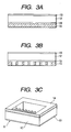
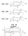
- FIGs. 3A through 3C to 5A through 5C are schematic views for explaining the liquid discharge head manufacturing method. This method does, however, not comprise all of the features of the invention.
- a portion for defining the common liquid chamber is patterned by using a known technique such as photolithography.
- an SiN film 14 (material of nozzles) having a thickness of about 30 ⁇ m is formed on the film 13 by a microwave CVD method (referred to as " ⁇ W-CVD method" herein after).
- Gas used for forming the SiN film in the ⁇ W-CVD method may be mixed gas of monosilane (SiH 4 ), nitrogen (N 2 ) and argon (Ar).
- components of the gas used may include zinrane (Si 2 H 6 ) and/or ammonia (NH 3 ), as well as the above gas.
- the SiN film is formed under high vacuum of 5 mTorr by using a microwave having power of 1.5 kW and by supplying SiH 4 /N 2 /Ar having a flow rate of 100/100/40 sccm.
- the SiN film may be formed with other component ratios and by a CVD method using an RF power source.
- orifice portions and liquid passage portions are patterned by using a known technique such as photolithography, and etching is effected to obtain a trench structure by using an etching device utilizing dielectric coupled plasma.
- TMAH tetramethyl-ammonium-hydroxide
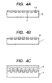
- a PSG (Phospho-Silicate Glass) film 17 having a thickness of about 5 ⁇ m is formed on an element substrate 16 (described later) by using a plasma CVD method.
- the thickness of the PSG film ultimately determines heights of the second liquid passages, in consideration of balance of the entire liquid passages depending upon liquid supply conditions to the second liquid passages, it is desirable that the thickness is selected to a value for achieving the most excellent efficiency of the movable member.
- portions of PSG film other than portions defining the second liquid passages and the second common liquid chamber are patterned by using a known technique such as photolithography, and an SiN film 18 (defining the separation diaphragm between the first liquid passages and the second liquid passages) having a thickness of about 1 ⁇ m is formed on the PSG film.
- This SiN film is generally used in a semi-conductor process and have good alkali resistance, chemical stability and good ink resistance.
- As composition of the SiN film, Si 3 N 4 is the best, but, in consideration of the efficiency of the movable diaphragm, Si:N may be selected to 1 : 1 to 1.5.
- a thickness of the movable diaphragm made of inorganic material such SiN is desirably 1000 ⁇ - 1 ⁇ m (in case of SiN), depending upon materials.
- a plurality of opening portions (not shown in Figs. 4A to 4C; refer to Fig. 1) as supplying openings and discharging openings for forming the liquid moving paths defined by the second common liquid chamber and the second liquid passages are patterned by using a known technique such as photolithography. Cylindrical through-holes having a diameter of 10 to 50 ⁇ m are formed (by etching) in the rear surface of the element substrate 16 by an etching device using dielectric coupled plasma.
- the etching can be stopped at a certain location on the PSG film.
- a heat accumulation layer 103 (described later) can previously be removed.
- the second liquid passages are formed, thereby completing the head substrate integral with the movable diaphragm.
- solvent for example, buffered fluoroacid
- the movable diaphragm is formed integrally with the head substrate having the portion for securing the movable diaphragm, it is not required that a very thin movable having a thickness of about 1 ⁇ m is handled as a single piece.
- the movable diaphragm can be formed integrally with the head substrate having the heat generating resistance elements, the positioning of the movable diaphragm with respect to the heat generating resistance elements can be effected more correctly, thereby preventing dispersion in discharging ability from part to part. Further, since the second liquid passages are formed by utilizing the semi-conductor manufacturing process, the pitch between the liquid passages can be reduced to about 10 to 20 pm, thereby realizing high density arrangement of the nozzles easily.
- any material can be used.
- SiN is used as the movable separation diaphragm and buffer fluoroacid is used as the solvent
- BPSG Boron-doped Phospho-Silicate Glass
- the joining therebetween can be effected by low noise (room temperature) joining using surface activity (referred to merely as “room temperature joining” hereinafter).
- a room temperature joining device used in this case comprises an auxiliary chamber and a joining chamber (both are vacuum chambers), and vacuum of 1 to 10 Pa is used.
- the auxiliary chamber an alignment position for positioning a portion for joining the liquid discharge head substrate 1 and the orifice integral type top plate 6 is determined by using image treatment. Thereafter, while such a condition is being maintained, the assembly is conveyed into the joining chamber, where energy particles are applied to the surface of the SiN film at the portion to be joined. After the surface is activated by such application, the liquid discharge head substrate 1 and the orifice integral type top plate 6 are joined. In this case, in order to increase strength, temperature of 200°C or more or pressure may be applied.
- the substrate may be joined to the top plate at a temperature of about 100°C, or, after adhesive is coated on one of the discharge head substrate and the top plate by a transferring method, the joining may be effected with heat and pressure.
- the top plate and the head substrate are joined, since the top plate, movable diaphragm and head substrate are formed from material including silicon element, influence due to thermal expansion is affected on these parts in the same manner, thus improving heat resistance. Therefore, even when the assembling (joining) is performed under a high temperature condition, the movable portions of the diaphragm can be prevented from being deviated from the liquid passages.
- the material is not limited to the silicon element, but the top plate, movable diaphragm and head substrate may be formed from same element.
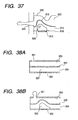
- the orifice portions are worked by an ion beam 19 while using a mask 20 under vacuum.
- the working due to power of the ion beam, the working can be effected in an inverted taper.
- the head can be completed.
- a laser abrasion using excimer laser may be effected under normal temperature/pressure.
- SiN material is suitable.
- SiN is best, then, SiC and Si are better, and SiO 2 is worst.
- the diaphragm including the silicon is formed by the plasma CVD method.
- the face of the inorganic insulation diaphragm formed by the laser abrasion has an adequate sharp configuration as it is, in order to obtain a more sharp configuration, a polishing process may be added.
- Figs. 6A to 6E are schematic sectional views (taken along a direction of the liquid passage) for explaining the manner that the liquid is discharged from the liquid discharge head of Fig. 1 in a time-lapse fashion.
- the first liquid passages 3 directly communicated with the discharge ports 11 are filled with first liquid supplied from the first common liquid chamber 143, and the second liquid passages 4 having the bubble generating areas are filled with the bubbling liquid from which a bubble can be formed by applying thermal energy from the heat generating member 2.
- the liquid in the first liquid passage 3 is conveyed near the discharge port 11 by a capillary force.
- the discharge port 11 is located at a downstream side of the projection area of the heat generating member 2 onto the first liquid passage 3 in a liquid flowing direction in the first liquid passage 3.
- the second liquid flows to be shifted in the second liquid passage in a direction shown by the arrows.
- the heat generating member 2 when the thermal energy is applied to the heat generating member 2, the heat generating member 2 is heated quickly, with the result that the second liquid contacted with the bubble generating area is heated to generate the bubble (Fig. 6B).
- the bubble 7 is generated by a film boiling phenomenon described in the U.S. Patent No. 4,723,129 and is formed on the entire surface of the heat generating member with high pressure.
- the pressure generated in this case is propagated through the second liquid in the second liquid passage 4 to act on the movable separation diaphragm 5, with the result that the movable separation diaphragm 5 is deformed to start the discharging of the first liquid in the first liquid passage 3.
- the liquid discharge head substrate 1, movable separation diaphragm 5 and top plate 6 are formed from material including the same element. Accordingly, since the influence due to heat accumulation acts on these members in the same manner, in use, the joined portions between the liquid discharge head substrate 1, movable separation diaphragm 5 and top plate 6 are not subjected to excessive forces. Therefore, since the assembling accuracy in the manufacture is improved and the movable portions and fixed portions of the movable diaphragm can surely be functioned as the movable portions and fixed portions, respectively, a highly fine output image can be obtained stably.
- the top plate is formed from the material including silicon, heat radiating ability of the head can be improved in comparison with a head made of resin. Further, since the liquid passage walls defining the liquid passages for the discharge liquid are formed from SiN as well as the movable separation diaphragm, ink resistance can be enhanced. With such additional feature, the above-mentioned effect (in the illustrated embodiment) that the highly fine output image can be obtained stably becomes further excellent.
- the second common liquid chamber communicated with the second liquid passages is defined by the movable separation diaphragm 5.
- the side walls defining the second liquid passage are extended up to an upstream point of the rear end of the heat generating resistance element 2.
- the second common liquid chamber is defined by the diaphragm, there is obtained an effect that the cross-talk of the bubbling liquid due to the bubbling can be further suppressed.
- it is desirable that the second common liquid chamber is opposed to the first common liquid chamber with the interposition of the movable separation diaphragm.
- Fig. 7 is a sectional view of a liquid discharge head according to a second embodiment of the present invention, taken along a direction of a liquid passage
- Fig. 8 is a sectional view of the liquid discharge head of Fig. 7, taken along a direction perpendicular to the plurality of liquid passages.
- elements having the same function as that of the first embodiment are designated by the same reference numerals.
- second liquid passages 4 for bubbling liquid are located on a liquid discharge head substrate 1 on which heat generating elements 2 for affording bubble generating thermal energy to liquid are arranged, and first liquid passages 3 (for discharge liquid) communicated with discharge ports 11 are provided on the second liquid passages.
- the first and second liquid passages correspond to the respective heat generating elements 2.
- a movable separation diaphragm 5 having elasticity are disposed between the first and second liquid passages, so that the discharge liquid in the first liquid passages 3 is completely isolated from the bubbling liquid in the second liquid passages 4.
- the discharge liquid in the first liquid passages 3 and the bubbling liquid in the second liquid passages 4 are supplied from respective supply paths.
- the first liquid passages 3 communicated with the discharge ports 11 are formed by joining the top plate 6 to the liquid discharge head substrate 1. That is to say, the top plate 6 is constituted by an orifice plate having the discharge ports 11, a plurality of grooves for defining the plurality of first liquid passages 3, and a recess defining a first common liquid chamber 143 commonly communicated with the plurality of first liquid passages 3 to supply liquid (discharge liquid) to the first liquid passages 3.
- the separation diaphragm 5 is made of material having elasticity and having heat resistance against a temperature of about 300°C, oil resistance, solvent resistance and chemical resistance. Further, good diaphragm forming ability by using coating or deposition is desirable.
- polyparaxylirene used in a surface film of a silicone rubber elastic body may be used. Such material has good adhering ability to silicone material and good elasticity and, from such material, a thin film can be obtained by a vapor-phase deposition polymerization method.
- a fluororesin film is also suitable for the separation diaphragm of the liquid discharge head of the present invention. After water paint of fluororesin (for example, FEP, PFA, PTFE) is coated, a film is formed by heating firing. The fluororesin also has good adhering ability to silicone material and good elasticity.
- Joining members 130a, 130b for fixing the separation diaphragm 5 and for joining first liquid passage walls 3a and first common liquid chamber frame to second liquid passage walls 4a and second common liquid chamber frame are disposed on and under the separation diaphragm 5.
- the top plate, head substrate and joining members 130a, 130b are all made of material including silicon element.
- the top plate is formed from the material including silicon, heat radiating ability of the head can be improved in comparison with a head made of resin, and, the above-mentioned effect (in the illustrated embodiment) that the highly fine output image can be obtained stably becomes further excellent, as is in the first embodiment.
- the side walls defining the second liquid passages are extended up to a point upstream of the rear ends of the heat generating resistance elements 2 and the second common liquid chamber is opposed to the first common liquid chamber with the interposition of the movable separation diaphragm, the cross-talk of the bubbling liquid due to the bubbling can be further suppressed.
- the liquid passage walls 3a (side walls of the first liquid passages) for defining the first liquid passages are extended up to the first common liquid chamber 143 at the point upstream of the rear ends of the heat generating resistance elements 2, and there is no upper wall there.
- an SiN film 118 (forming the liquid passage walls 4a defining the second liquid passages) having a thickness of about 5 ⁇ m is formed on an element substrate 16 (fully described later) by the ⁇ W-CVD method.
- the second liquid passages and the second common liquid chamber (not shown) are formed by using a known technique such as photolithography.
- a plurality of supply opening portions for supplying the bubbling to the second common liquid chamber and for shifting the bubbling liquid from the second liquid passages are patterned by using a known technique such as photolithography.
- cylindrical through-holes having a diameter of 50 ⁇ m are formed (by etching) in the rear surface of the element substrate by an etching device using dielectric coupled plasma.
- a heat accumulation layer 103 (described later) is previously removed from areas where the through-holes are formed.
- the orifice integral type top plate 6 is joined to the substrate with the interposition of the movable separation diaphragm which will be described later.
- the orifice integral type top plate 6 is manufactured by the processes shown in Figs. 3A to 3C, and parts of the first liquid passage walls and the first common liquid chamber frame are formed from the SiN film.
- the joining between the substrate and the top plate and the movable separation diaphragm can be effected by room temperature joining.
- the head is completed by working the orifice portions (Figs. 5A to 5C).
- an SiN film having a thickness of about 3 ⁇ m (defining the joining member 130a constituting the joining portion to the orifice integral type top plate 6) is formed on a silicone wafer 17 by using the ⁇ W-CVD method. And, etching is effected by using a known technique such as photolithography to remain required portions alone.
- a film of polyparaxylilene having a thickness of about 5 ⁇ m is formed as the movable separation diaphragm 5 by a vapor-phase deposition polymerization method.
- Fundamental structure, manufacturing method and polymerization of polyparaxylilene used in the present invention are disclosed in U.S. Patent No. 3,379,803 and Japanese Patent Publication Nos. 44-21353 and 52-37479.
- an SiN film having a thickness of about 2 ⁇ m (defining the joining member 130b constituting the joining portion to the liquid discharge head substrate 1) is formed by using the ⁇ W-CVD method. And, etching is effected by using a known technique such as photolithography to remain required portions alone.
- the silicone substrate 17 is removed by an etching method using chemical mechanical polishing (CMP) or TMAH.
- CMP chemical mechanical polishing
- TMAH TMAH
- the silicone wafer may be removed by exposing the substrate to XeF 2 gas.
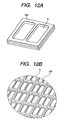
- Fig. 12A is a perspective view of the separation diaphragm having the joining members integrally formed therewith manufactured by the above processes.
- Fig. 12A is a view of the separation diaphragm having the joining members integrally formed therewith of Fig. 10D or Fig. 11E, looked at from below.
- the joining members on the movable diaphragm in the manufacture, when the movable diaphragm is handled, adequate strength or rigidity is ensured, thereby preventing the damage of the movable diaphragm and permitting easy and correct alignment during the assembling.
- the fixed end portions of the diaphragm (during the deformation of the diaphragm) can surely act as the fixed ends without the joining to the top plate and the substrate and the fixed end portions can be manufactured with high accuracy, dispersion from part to part and dispersion depending upon use conditions can be avoided, thereby providing a liquid discharge head having stable discharging ability and capable of a highly fine image, and the nozzles can easily be arranged with high density.
- the handling ability in the manufacture is enhanced, and, by covering the deformable portions of the movable diaphragm by the joining members (i.e., as shown in Fig. 12A, the joining members have closed openings) to clearly define the fixed ends of the diaphragm, the diaphragm is clearly divided into the movable portions and the fixed portions, thereby achieving the excellent effect.
- the silicone wafer is used as a tool for manufacturing the joining members and the movable separation diaphragm, these parts can be manufactured under a high temperature condition, and, since the thin film forming technique is used, the parts can be manufactured with high accuracy under a clean environment without creating any pinhole.
- a plurality of separation diaphragms having joining members formed integrally therewith shown in Fig. 12A may be formed on the silicone wafer to obtain the plurality diaphragms at once. In this case, although the article must be cut in correspondence to the head, a large number of diaphragms having movable portions and fixed portions with high accuracy can be manufactured at a time.
- the SiN film constituting the joining member 130b defining the joined portion to the liquid discharge head substrate 1 may be formed. According to this method (processes corresponding to Figs. 10A and 10B are shown in Figs. 11A and 11B, and processes corresponding to Figs. 10C and 10D are shown in Figs.
- the movable separation diaphragm can be positively held by the joining members from both sides, and, when a plurality of movable separation diaphragms with the joining members are formed on the silicone wafer collectively and the article is cut in accordance with the head, since the joining members joined together rather than the diaphragm itself are cut, the cutting process can be effected accurately at a high speed, and the influence of the cutting apparatus can be reduced and dispersion from part to part can be reduced.
- Figs. 13A to 13E are explanatory views for explaining the liquid discharging operation of the liquid discharge head according to the second embodiment.
- a second liquid passage 504 for the bubbling liquid is provided on a substrate 510 on which a heat generating member 502 (in this embodiment, a heat generating resistance body having dimension of 40 ⁇ m ⁇ 105 ⁇ m) for generating thermal energy for creating a bubble in the liquid, and a first liquid passage 503 directly communicated with a discharge port 501.
- a heat generating member 502 in this embodiment, a heat generating resistance body having dimension of 40 ⁇ m ⁇ 105 ⁇ m
- a movable separation diaphragm 505 formed from a thin film made of inorganic material having elasticity is disposed between the first liquid passage 503 and the second liquid passage 504, so that discharge liquid in the first liquid passage 503 is isolated from bubbling liquid in the second liquid passage 504.
- the deformation of the movable separation diaphragm 505 is limited by a joining member 531 joined to liquid passage walls of the first liquid passage.
- the joining member can be manufactured integrally with the movable separation diaphragm by using the above-mentioned method.
- the joining members may be formed.
- the joining members movable diaphragm deformation regulating member
- the same handling ability of the diaphragm as that in the manufacturing method according to the second embodiment can be obtained.
- a metal film having the same dimension as the movable diaphragm is formed as an etching stop layer, and the joining members can be formed by over etching by using a dry etching process.
- Fig. 13A energy such as electrical energy is not applied to the heat generating member 502, so that heat is generated from the heat generating member 502.
- the movable separation diaphragm 505 is located at a first position substantially parallel with the substrate 501.
- a center of the opening of the joining member 531 is located at a downstream side of a center of the heat generating member 502, so that a center of the movable area of the movable separation diaphragm 505 is positioned at a downstream side of the center of the heat generating member 502.
- the movable separation diaphragm 505 is returned to the initial position (first position). Further, when the bubble is disappeared, in order to compensate the loss of volume of the liquid, the liquid flows in from the upstream side, i.e., from the common liquid chamber (as shown by the arrows V D1 , V D2 ) and from the discharge port 501 (as shown by the arrow V C ). In this case, during the growth of the bubble, since the liquid flow toward the downstream side (toward the discharge port), the flows V D1 , V D2 become great, the re-fill speed is improved and a retard amount of meniscus can be suppressed.
- the joining member is chamfered to prevent concentration of stress in the movable separation diaphragm 505 at the edge of the joining member, thereby reducing deterioration in strength and improving endurance.
- Figs. 14A to 14D are views showing a positional relation between the heat generating member 502 and the second liquid passage 504 and the joining member 531
- Fig. 14A is a view showing a positional relation between the heat generating member 502 and the second liquid passage 504
- Fig. 14B is a view showing the joining member 531 looked at from the above
- Fig. 14C is a view showing a positional relation between the heat generating member 502 and the second liquid passage 504 and the joining member 531
- Fig. 14D is a view in which an upward deformable area and a downward deformable area of the movable separation diaphragm 505 are indicated by different hatched zones; in these Figures, the discharge port is located at the left.
- a portion surrounded by the walls of the second liquid passage 504 corresponds to the downward deformable area of the movable separation diaphragm 505 and a portion within the opening of the joining member 531 corresponds to the upward deformable area of the movable separation diaphragm 505, and the center of the movable area of the movable separation diaphragm 505 is located at a downstream side of the center of the heat generating member 502.
- the deformable areas are differentiated; however, as is in the second embodiment, when the upper and lower joining members are provided, by differentiating the openings of the upper and lower joining members (more specifically, the opening of lower joining member facing to the second liquid passages is made greater than the opening of the upper joining member facing to the first liquid passages), the deformable areas may be differentiated.
- the movable separation diaphragm 505 in the opening of the joining member 531, by providing "R" at four corners, the movable separation diaphragm 505 can be prevented from being broken and the endurance of the diaphragm can be improved.
- the movable separation diaphragm deformed by the increased force due to the growth of the bubble is frown toward the downstream side by positioning the center of the movable area of the movable separation diaphragm at the center of the heat generating member, liquid weak to heat or high viscous liquid can be efficiently discharged with high pressure. Further, due to the transporting action of the liquid in the first liquid passage, the discharge amount can be increased.
- Fig. 15 is a sectional view of a liquid discharge head according to a third embodiment of the present invention, taken along a direction of a liquid passage
- Fig. 16 is a sectional view of the liquid discharge head of Fig. 15, taken along a direction perpendicular to the plurality of liquid passages.
- the liquid discharge head according to this embodiment differs from that of the second embodiment in the point that a movable member 131 made of the same material as that of a joining member 130 is disposed on a separation diaphragm 5. Further, in this embodiment, as is in the second embodiment, the liquid passage walls 3a for defining the first liquid passages (side walls of the first liquid passages) is extended up to the first common liquid chamber 143 at the upstream side of the rear ends of the heat generating resistance bodies 2, and there is no upper wall there.
- the diaphragm in the manufacturing process of the movable separation diaphragm, can be manufactured in the same manner as the second embodiment, except that the joining members and the movable member are integrally formed with each other.
- the manufacturing process of the movable separation diaphragm will be briefly described with reference to Figs. 17A to 17D.
- an SiN film having a thickness of about 3 ⁇ m (defining the joining member 130a constituting the joining portion to the orifice integral type top plate 6 and the movable member 131) is formed on a silicone wafer 17 by using the ⁇ W-CVD method. And, etching is effected by using a known technique such as photolithography to remain required portions alone.
- a film of polyparaxylilene is formed as the movable separation diaphragm 5, and, then, as shown in Fig. 17C, an SiN defining the joining member 130b constituting the joining portion to the liquid discharge head substrate 1 is formed. And, etching is effected by using a known technique such as photolithography to remain required portions alone, and thereafter, as shown in Fig. 17D, the silicone substrate 17 is removed.
- Figs. 18A and 18B are perspective views of the separation diaphragm having the movable member formed integrally therewith (movable member integral type separation diaphragm), where Fig. 18A is a view of the movable member integral type separation diaphragm looked at from the above, and Fig. 18B is a view of the movable member integral type separation diaphragm looked at from the below. Also in this embodiment, in the manufacturing method, the same effect as the second embodiment can be achieved. Accordingly, a plurality of diaphragms may be formed on the silicone wafer to obtain the plurality of diaphragms at once.
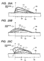
- Fig. 19A shows a non-bubbling condition
- Fig. 19B shows a bubbling (discharging) condition
- Fig. 19C shows a bubble disappearing condition.
- the joining members are omitted from illustration.
- a second liquid passage 604 for the bubbling liquid is provided on a substrate 610 on which a heat generating member 602 (in this embodiment, a heat generating resistance body having dimension of 40 ⁇ m ⁇ 105 ⁇ m) for generating thermal energy for creating a bubble in the liquid, and a first liquid passage 603 directly communicated with a discharge port 601 is provided on the second liquid passage.
- a heat generating member 602 in this embodiment, a heat generating resistance body having dimension of 40 ⁇ m ⁇ 105 ⁇ m
- a movable separation diaphragm 605 formed from a thin film made of inorganic material having elasticity is disposed between the first liquid passage 603 and the second liquid passage 604, so that discharge liquid in the first liquid passage 603 is isolated from bubbling liquid in the second liquid passage 604 by the movable separation diaphragm 605.
- the movable separation diaphragm 605 is disposed in a confronting relation to the heat generating member 602 and is opposed to at least a part of a bubble generating area 607 where a bubble is created by heat from the heat generating member 602.
- a movable member 631 having a free end 631a disposed above the bubble generating area 607 and a fulcrum 631b at an upstream side of the free end 631a is arranged adjacent to the movable separation diaphragm 605.
- the free end 631a of the movable member 631 even when the free end is not disposed in a confronting relation to the bubble generating area 607, so long as the free end is disposed at a downstream side of the fulcrum 631b to direct the deformation of the movable separation diaphragm 605 toward the discharge port 601 (more preferably, the free end is opposed to at least a part of the heat generating member 602 with the interposition of the movable separation diaphragm 605), the displacement of the movable separation diaphragm 605 can be controlled effectively.
- the movable member 631 is disposed in a confronting relation to the movable separation diaphragm 605 so that the free end 631a is located at a downstream side of the center of the heat generating member 602 or the bubble generating area 607, since the movable member 631 can concentrate components tending to expand in a direction perpendicular to the heat generating member 602 toward the discharge port 601, the discharging efficiency is remarkably increased. Further, even if the free end 631a is located at the downstream side of the bubble generating area 607, by displacing the free end 631a greatly to displace the movable separation diaphragm 605 toward the discharge port 601 greatly, the discharging efficiency is enhanced.
- a bubble 606 is created in the bubble generating area 607 on the heat generating member 602 to displace the movable separation diaphragm 605 toward the first liquid passage 603.
- the displacement of the movable separation diaphragm 605 is regulated by the movable member 631.
- the movable separation diaphragm 605 is displaced more greatly toward the downstream side than the upstream side (Fig. 19B).
- a desired deformation and displacement can be obtained stably by a direction regulating means for regulating a direction along which the movable separation diaphragm 605 is displaced.
- the movable separation diaphragm 605 is returned toward the initial non-deformed position.
- the movable separation diaphragm 605 will be displaced toward the second liquid passage 604 from the non-deformed position due to the pressure of the contracted bubble.
- the movable separation diaphragm 605 is integral with the movable member 631, the displacement of the movable separation diaphragm 605 toward the second liquid passage 604 can be suppressed (Fig. 19C).
- the reduction in pressure in the first liquid passage 603 is suppressed to suppress the retard amount of meniscus, thereby improving the re-fill feature.
- the shifting of the liquid toward the upstream side is suppressed by the movable member 631, thereby improving the re-fill feature and reducing the cross-talk.
- the discharge liquid and the bubbling liquid are provided independently, and only the discharge liquid can be discharged.
- high viscous liquid such as polyethylene glycol in which the bubble is not adequately created by heat to result in poor discharging
- by supplying this liquid to the first liquid passage 603 and by supplying liquid (mixed liquid of about 1-2 cp having ethanol : water 4 : 6) which can easily create the bubble to the second liquid passage 604 as the bubbling liquid, the good discharging can be achieved.
- the generation of the bubble can be stabilized and the good discharging can be achieved.
- liquid such as high viscous liquid can be discharged with high discharging efficiency and with high discharging force.
- liquid weak to heat is used, so long as this liquid is supplied to the first liquid passage 603 as the discharge liquid and liquid which is hard to be deteriorated by heat and which can create the bubble conveniently is supplied to the second liquid passage 604, the liquid weak to heat is not subjected to thermal demerit, and the liquid can be discharged with higher discharging efficiency and with higher discharging force.
- the liquid can be discharged at higher speed with higher discharging force and higher discharging efficiency than the conventional liquid discharging apparatuses.
- the bubbling liquid having the above-mentioned feature may be used; more specifically, the bubbling liquid may be methanol, ethanol, n-propanol, isopropanol, n-xane, n-heptane, n-octane, toluene, xylene, methylene dichloride, trichlene, fleone TF, fleone BF, ethyl ether, dioxiane, cyclohexane, methyl acetate, ethyl acetate, acetone, methyl ethyl ketone, water and mixtures thereof.
- the discharge liquid various liquids may be used regardless of presence/absence of bubbling ability and thermal property. Further, even liquid having poor bubbling ability, liquid which is deteriorated and degraded by heat or liquid high viscous liquid which were conventionally hard to be discharged can be used.
- high viscous ink can be used.
- liquids such as medical liquid or perfume which is weak to heat can be used.
- the bubbling liquid and the discharge liquid having the following compositions are used for effecting the recording.
- the liquid having high viscosity of 150 cp, as well as the liquid having viscosity of ten-odd cp which was hard to be discharged can be discharged effectively, thereby obtaining a high quality image.
- the joining members of the movable diaphragm was firstly formed and then the movable diaphragm was formed.
- the joining member as the frame may be provided on one surface of the diaphragm rather than both surfaces, the movable separation diaphragm may be firstly formed on the Si wafer. Even when the movable diaphragm is firstly formed and then the joining member (and, if necessary, a cantilever movable member) is formed, the same advantage such as good handling ability of the diaphragm as the second and third embodiments can be achieved.
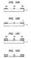
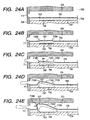
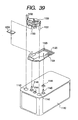
- Figs. 20A1 to 20D2 are explanatory views for explaining processes for manufacturing a liquid discharge head in which a top plate and a separation diaphragm are integrally manufactured in a sequence from Fig. 20A1 to 20D2, where Figs. 20A1, 20B1, 20C1 and 20D1 are perspective views, and Figs. 20A2, 20B2, 20C2 and 20D2 are sectional views taken along a direction perpendicular to a plurality of liquid passages.
- a polyparaxylilene film is formed on a silicone wafer 17 as a movable separation diaphragm 5.
- a wall surface 14 for defining orifices, first liquid passages and a common liquid chamber is formed as a SiN film, for example, by a ⁇ W-CVD method. And, etching is effected by using a known technique such as photolithography to remain required portions alone.
- a flat plate 16 having a through-hole as a liquid supply opening of the common liquid chamber previously formed by etching is joined to the wall surface 14 defining the liquid passages and the common liquid chamber, thereby forming the top plate integral with the movable diaphragm.
- the silicone wafer 17 is removed, and, the assembly is joined to the liquid discharge head substrate 1 (for example, manufactured by the manufacturing method in the second embodiment shown in Figs. 9A and 9B) having the liquid passage walls (desirably formed from SiN) of the second liquid passages and the heat generating resistance elements 2, thereby joining the top plate and the head substrate together, as shown in Figs. 20D1 and 20D2.
- the movable separation diaphragm and the liquid passage walls 4a constitute the second liquid passages.
- the liquid discharge head having the movable separation diaphragm can be manufactured.
- liquid discharge head manufacturing method since the liquid passages and the movable separation diaphragm can be formed integrally, there is no positional deviation of the diaphragm with respect to the liquid passages, and, thus, a liquid discharge head having high reliability no dispersion in discharging ability from part to part can be provided.
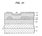
- Fig. 21 is a sectional view showing a portion corresponding to a head generating element (bubble generating area) of a liquid discharge head substrate 1.
- the reference numeral 101 denotes a silicone substrate and 102 denotes a heat oxidized film as a heat accumulation layer.
- the reference numeral 103 denotes an SiO 2 or Si 2 N 4 film as a layer-to-layer film also acting as a heat accumulation layer; 104 denotes a resistance layer; and 106 denotes an SiO 2 or Si 2 N 4 film as a protection layer; and 105 denotes a wiring made of aluminium or aluminium alloy such as Al-Si or Al-Cu.
- the reference numeral 107 denotes anti-cavitation film for protecting the protection layer 106 from chemical and physical shock caused due to the heating of the resistance layer 104; and 108 denotes a heat acting portion of the resistance layer 104 where an electrode wiring 105 is not formed.
- These driving elements are formed on an Si substrate by a semi-conductor technique, and the heat acting portion is further formed on the same substrate.
- Fig. 22 is a schematic longitudinal sectional view showing the main elements.
- P-MOS450 is formed in an N-type well area and N-MOS451 is formed in a P-type well area on an Si substrate 401 made of P conductor by impurity introduction and diffusion such as ion platation by using a general MOS process.
- the P-MOS450 and N-MOS451 are constituted by gate wirings 415 of poly-Si deposited to a thickness of 4000 to 5000 ⁇ by a CVD method through a gate insulation film 408 having a thickness of several hundred ⁇ , and source areas'405 and drain areas 406 into which N-type or P-type impurity is introduced, and C-MOS logic is constituted by the O-MOS and N-MOS.
- an element driving N-MOS transistor is constituted by a drain area 411 and a source area 314 in the P-well substrate by the impurity introduction and diffusion process.
- the N-MOS transistor is used as a transistor has an ability for driving the plurality of heat generating element independently and a function capable of achieving the above-mentioned fine structure, the transistor is not limited to the N-MOS transistor.
- oxidized film separation areas 405 having a thickness of 5000-10000 ⁇ are formed by field oxidation to separate the elements from each other.
- the field oxidized films act as a first heat accumulation layers under the heat acting portion 108.
- a layer-to-layer insulation film having a thickness of about 7000 ⁇ is formed by depositing PSG film and BPSG film by using the CVD method, and, after flattened by heat treatment, the wiring is effected by an aluminium electrode 417 as a first wiring layer through a contact hole.
- a layer-to-layer insulation film 418 such as SiO 2 film having a thickness 10000-15000 ⁇ is formed by the plasma CVD method, and, further, a TaN 0.8hex as a resistance layer 104 having a thickness of about 100 ⁇ is formed by a DC spattering method through a through-hole.
- an aluminium electrode as a second wiring layer for wiring to the various elements is formed.
- the protection layer 106 As the protection layer 106, an Si 3 N 4 film having a thickness of about 10000 ⁇ is formed by the plasma CVD method. As an uppermost layer, the anti-cavitation film 107 made of Ta and having a thickness of about 2500 ⁇ is formed.
- Figs. 23A through 23E to 25A through 25C are views for explaining an example of the discharging method of the above-mentioned liquid discharge head.
- the discharge ports are arranged at end areas of the first liquid passages, and the deformable areas of the movable separation diaphragm which are deformed as the generated bubble is being grown are disposed at an upstream side of the discharge ports (with respect to a flow direction of the liquid in the first liquid passages).
- the second liquid passages contain the bubbling liquid or are filled with the bubbling liquid (preferably, the bubbling liquid can be loaded, and, more preferably, the bubbling liquid can be shifted), and each has the bubble generating area.
- the bubble generating area is also disposed at the upstream side of the corresponding discharge port with respect to the flowing direction of the discharge liquid.
- the separation diaphragm has the movable areas having a length longer than each electrothermal converting element, and has the fixed portion between the upstream ends of the electrothermal converting elements and common liquid chamber for the first liquid passages (preferably, at the upstream ends). Accordingly, the substantial movable range of the separation diaphragm can be understood from Figs. 23A through 23E to 25A through 25C.
- the conditions of the movable separation diaphragm shown in these Figures are determined by elasticity and thickness of the separation diaphragm itself or other additional structure.
- Figs. 23A to 23E are sectional views (taken along a direction of the liquid passage) for explaining a first discharging method of the liquid discharge head according to the present invention.
- a first liquid passage 703 directly communicated with a discharge port 711 is filled with first liquid supplied from a first common liquid chamber 743, and a second liquid passage 704 having a bubble generating area 707 is filled with bubbling liquid in which a bubble is created by applying thermal energy to the liquid from a heat generating member 702.
- a movable separation diaphragm 705 for isolating the first liquid passage 703 and the second liquid passage 704 from each other is disposed between the first liquid passage 703 and the second liquid passage 704. Further, the movable separation diaphragm 705 and an orifice plate 709 are closely secured to each other to prevent the mixing of the liquids in the first and second liquid passages.
- the diaphragm 705 When the movable separation diaphragm 705 is displaced by the bubble generated in the bubble generating area, the diaphragm has no direction, or, rather, tends to advance toward the common liquid chamber having great degree of freedom regarding displacement.
- the movement of the movable separation diaphragm 705 is considered, and, a means for regulating the direction of displacement of the diaphragm, which means acts on the movable separation diaphragm 705 itself directly or indirectly, so that the displacement (shifting, expansion or elongation) of the movable separation diaphragm 705 caused by the bubble is directed toward the discharge port.
- the liquid in the first liquid passage 703 is drawn up to the vicinity of the discharge port 711 by a capillary force.
- the discharge port 711 is disposed at a downstream side of a projected area of the heat generating member 702 projected onto the first liquid passage 703 with respect to the liquid flowing direction in the first liquid passage 703.
- the heat generating member 702 in this example, heat generating resistance body having dimension of 40 ⁇ m x 105 ⁇ m
- the heat generating member 702 is heated quickly, with the result that the second liquid in the bubble generating area 707 is heated to create a bubble 706 (Fig. 23B).
- the bubble 706 is generated by a film boiling phenomenon disclosed in U.S. Patent No. 4,723,129 and is created with great high pressure on the entire surface of the heat generating member 702.
- the pressure generated in this case is propagated through the second liquid in the second liquid passage 704 as a pressure wave and then acts on the movable separation diaphragm 705, with the result that the movable separation diaphragm 705 is displaced to start the discharging of the liquid in the first liquid passage 703.
- the bubble 706 created on the entire surface of the heat generating member 702 is grown quickly, the bubble becomes a film shape (Fig. 23C).
- the expansion of the bubble 706 by the great high pressure in the initial phase of the bubble generation causes the movable separation diaphragm 705 to further displace, with the result that the discharging of the liquid in the first liquid passage 703 from the discharge port 711 is promoted.
- the displacement of the movable separation diaphragm 705 becomes great (Fig. 23D).
- the movable separation diaphragm 705 continues to expanded in such a manner that the displacement of an upstream side 705A of the movable separation diaphragm 705 (with respect to a central portion 705C opposed to the heat generating area 702) becomes substantially equal to a downstream side 705B.
- the movable separation diaphragm 705 since the movable separation diaphragm 705 has a process for displacing it toward the discharge port to directly shift the liquid toward the discharge port, the discharging efficiency is further improved. Further, the shifting amount of the liquid toward the upstream side is relatively decreased, with the result that the re-fill of the liquid into the nozzles (particularly, into the deformable area of the movable separation diaphragm 705) (replenishment from the upstream side) is improved.
- Figs. 24A to 24E are sectional views (taken along a direction of the liquid passage) for explaining a second discharging method of the liquid discharge head according to the present invention. Since this example is also substantially the same as the first discharging principle, explanation will be made by using the same reference numerals.
- the liquid in the first liquid passage 703 is drawn up to the vicinity of the discharge port 711 by a capillary force.
- the discharge port 711 is disposed at a downstream side of a projected area of the heat generating member 702 projected onto the first liquid passage 703.
- the bubble 706 created on the entire surface of the heat generating member 702 is grown quickly, the bubble becomes a film shape (Fig. 24C).
- the expansion of the bubble 706 by the great high pressure in the initial phase of the bubble generation causes the movable separation diaphragm 705 to further displace, with the result that the discharging of the liquid in the first liquid passage 703 from the discharge port 711 is promoted.
- a downstream side 715B of the movable area of the diaphragm is displaced more greater than an upstream side 715A. Accordingly, the first liquid in the first liquid passage 703 is shifted efficiently toward the discharge port 711 from the initial condition.
- the discharging efficiency (particularly, discharging speed) can be improved, and the re-fill of the liquid in the nozzles and the volume of the discharged liquid droplet can be stabilized.
- this nose configuration since the deformed configuration of the movable separation diaphragm 705 in this case resembles a human's nose, it is referred to as "nose configuration".
- this nose configuration includes an "S"-shaped configuration in which a point B which was at the upstream side in the initial condition is positioned at a point A which was downstream side in the initial condition, or, as shown in Fig. 24E, a configuration in which the points A and B are located at a similar position.
- Figs. 25A to 25C are sectional views (taken along a direction of the liquid passage) for explaining steps of displacement of the movable separation diaphragm during the discharging operation of the liquid discharge head according to the present invention.
- the bubble, first liquid passage and discharge port are omitted from illustration; but, in these Figures, as a fundamental are omitted from illustration; but, in these Figures, as a fundamental arrangement, the projection area of the heat generating member 702 in the second liquid passage 704 is the bubble generating area 707, and the second liquid passage 704 and the first liquid passage 703 are substantially isolated from each other by the movable separation diaphragm 705 always (i.e., during the displacement from the initial condition).
- the discharge port is provided at a downstream side of the downstream end (shown by the line H) of the heat generating member 702 and the supply portion for the first liquid is disposed at an upstream side.
- upstream side and downstream side are used with respect to the central portion of the movable range of the movable separation diaphragm 705 in the flow direction of the liquid in the liquid passage.
- the movable separation diaphragm 705 is gradually displaced sequentially ((1) ⁇ (2) ⁇ (3)) from the initial condition, so that the downstream side is displaced more greatly than the upstream side from the initial condition, and, particularly, since this provides a function for improving the discharging efficiency and for shifting the first liquid in the first liquid passage 703 toward the discharge port by the downstream displacement, the discharging speed can be improved.
- the movable range is substantially constant.
- the movable range of the movable separation diaphragm 705 is widened.
- an upstream end of the movable range is fixed. Since the downstream side of the movable separation diaphragm 705 is displaced more greatly than the upstream side and the growth of the bubble itself can be directed toward the discharge port, the discharging efficiency can be further enhanced.
- the downstream side and the upstream side are displaced to the same extent or the upstream side is displaced more greatly than the downstream side; however, as the bubble is further grown from a condition (3) to a condition (4), the downstream side of the movable separation diaphragm is displaced more greatly than the upstream side.
- the first liquid above the movable area can also be shifted toward the discharge port, thereby improving the discharging efficiency and increasing the discharge amount.
- liquid discharging methods having the above-mentioned steps or processes are included in the present invention
- the methods shown in Figs. 25A to 25C are not necessarily handled independently, but respective steps are also included in the present invention.
- the step including the nose configuration shown in Fig. 25C may be applied to the methods shown in Figs. 25A and 25B.
- the thickness of the movable separation diaphragm illustrated does not limit the actual thickness.
- Figs. 26A to 26C are views showing a first example of a liquid discharge head according to the present invention having the above-mentioned regulating means, where Fig. 26A is a sectional view (taken along a direction of the liquid passage) showing a non-bubbling condition, Fig. 26B is a sectional view (taken along a direction of the liquid passage) showing a bubbling condition, and Fig. 26C is a view showing a construction of a second liquid passage.
- a second liquid passage 804 for bubbling liquid is provided on a substrate 810 on which a heat generating member 802 for generating thermal energy for creating a bubble in the liquid, and a first liquid passage 803 directly communicated with a discharge port 801 is provided on the second liquid passage.
- a movable separation diaphragm 805 formed from a thin film made of inorganic material having elasticity is disposed between the first liquid passage 803 and the second liquid passage 804, so that discharge liquid in the first liquid passage 803 is isolated from bubbling liquid in the second liquid passage 804 by the movable separation diaphragm 805.
- the second liquid passage 804 is extended toward a downstream direction of the bubble generating area 807 located immediately above the heat generating member 802, so that flow resistance in the downstream of the heat generating member 802 becomes small, with the result that the pressure of the bubble created by the heat of the heat generating member 802 is apt to be directed toward the downstream direction.
- the movable separation diaphragm 805 is also displaced toward the downstream direction, thereby obtaining high discharging efficiency and discharging force.
- the effect can be started as soon as the bubble is created.
- the movable separation diaphragm 805 is quickly returned to the initial position (non-deformed condition) due to contraction of the bubble (reduction in pressure)
- the acting direction of the pressure can be controlled, and the re-fill speed of the discharge liquid into the first liquid passage 803 is increased, thereby achieving stable discharging even in the high speed recording.
- Figs. 27A and 27B are views showing a second example of a liquid discharge head according to the present invention having the above-mentioned regulating means, where Fig. 27A is a sectional view showing a non-bubbling condition, and Fig. 26B is a sectional view showing a bubbling condition.
- a wall of a second liquid passage 814 nearer the discharge port than the heat generating member 802 is tapered to be converged toward the discharge port.
- the flow resistance at the bubble generating area 807 and therearound becomes smaller toward the discharge port, with the result that pressure of a bubble 816 created by the heat of the heat generating member 802 is apt to be directed toward the discharge port, thereby obtaining high discharging efficiency and discharging force.
- Figs. 28A and 28B are sectional views (taken along a direction of the liquid passage) showing alterations of the liquid discharge head shown in Figs. 27A and 27B, where Fig. 28A is a view showing an alteration in which a part of the wall of a second liquid passage is formed in a stepped shape, and Fig. 28B is a view showing an alteration in which a part of the wall of a second liquid passage is formed to have a radius of curvature.
- a wall of a second liquid passage 824 nearer the discharge port than the heat generating member 802 is stepped to be converged toward the discharge port, and, in the alteration shown in Fig. 28B, a wall of a second liquid passage 834 nearer the discharge port than the heat generating member 802 is curved (to have a radius of curvature) to be converged toward the discharge port.
- Figs. 29A and 29B are views showing a third example of a liquid discharge head according to the present invention having the above-mentioned regulating means, where Fig. 29A is a top view showing a positional relation between a second liquid passage and a heat generating member, and Fig. 29B is a perspective view of Fig. 29A (a discharge port is disposed at the left in Fig. 29A).
- a width of the second liquid passage 844 is gradually widened from an upstream side to a downstream side.
- Figs. 30A to 30E are views for explaining a discharging operation of the liquid discharge head shown in Figs. 29A and 29B in a time-lapse manner, where (A) in Figs. 30A to 30E (left Figures) are sectional views taken along the line B-B in Fig. 29A, (B) in Figs. 30A to 30E (central Figures) are sectional views taken along the line A-A in Fig. 29A, and (C) in Figs. 30A to 30E (right Figures) are sectional views taken along the line C-C in Fig. 29A.
- the electrical energy is not applied to the heat generating member 842 not to generate heat from the heat generating member 842.
- the movable separation diaphragm 845 is located at a first position substantially parallel to the substrate 820.
- the generated bubble 846 is grown quickly by the heat from the heat generating member 842.
- the second liquid passage 844 has the configuration shown in Figs. 29A and 29B, a central portion of the bubble is greatly grown at the central portion and both end portions of the bubble are greatly grown at the downstream side, with the result that the movable separation diaphragm 845 is displaced accordingly (Fig. 30C).
- the flow resistance at the bubble generating area 847 and therearound becomes smaller toward the discharge port, with the result that pressure of the bubble 846 created by the heat of the heat generating member 842 is apt to be directed toward the discharge port, thereby obtaining high discharging efficiency and discharging force. Further, the first liquid in the projected portion of the heat generating member 842 can be shifted toward the discharge port, thereby increasing the discharge amount.
- Figs. 31A to 31C are views showing alterations of the liquid discharge head of Figs. 29A and 29B, where Fig. 31A is a view showing an alteration in which the width of the second liquid passage in the vicinity of the heat generating member is gradually widened in a stepped manner from the upstream side to the downstream side, Fig. 31B is a view showing an alteration in which the width of the second liquid passage in the vicinity of the heat generating member is gradually widened to have a certain radius of curvature from the upstream side to the downstream side, and Fig.
- 31C is a view showing an alteration in which the width of the second liquid passage in the vicinity of the heat generating member is gradually widened in an inverted of curvature from the upstream side to the downstream side.
- the discharge port is located at the left side.
- the width of the second liquid passage 854 in the vicinity of the heat generating member 842 is gradually widened in a stepped manner from the upstream side to the downstream side
- the width of the second liquid passage 864 in the vicinity of the heat generating member 842 is gradually widened to have a certain radius of curvature from the upstream side to the downstream side
- the width of the second liquid passage 874 in the vicinity of the heat generating member 842 is gradually widened in an inverted (with respect to Fig. 31B) of curvature from the upstream side to the downstream side.
- the flow resistance at the bubble generating area and therearound becomes smaller toward the discharge port, with the result that pressure of the bubble created by the heat of the heat generating member is apt to be directed toward the discharge port, thereby obtaining high discharging efficiency and discharging force.
- Fig. 32 is a sectional view (taken along a direction of the liquid passage) showing a fourth example of a liquid discharge head according to the present invention having the above-mentioned regulating means.
- a second liquid passage 904 for bubbling liquid is provided on a substrate 908 on which a heat generating member 902 (in this example, heat generating resistance body having dimension of 40 ⁇ m ⁇ 105 ⁇ m) for generating thermal energy for creating a bubble in the liquid, and a first liquid passage 903 directly communicated with a discharge port 901 is provided on the second liquid passage.
- a movable separation diaphragm 905 formed from a thin film made of inorganic material having elasticity is disposed between the first liquid passage 903 and the second liquid passage 904, so'that discharge liquid in the first liquid passage 903 is isolated from bubbling liquid in the second liquid passage 904 by the movable separation diaphragm 905.
- the movable separation diaphragm 905 is greatly displaced toward the discharge port.
- the pressure of the bubble created in the bubble generating area 907 is directed toward the discharge port 901.
- Figs. 33A to 33D are views for explaining the operation of the liquid discharge head shown in Fig. 32.
- the flow resistance in the downstream side (discharge port side) of the center of the heat generating member 902 is selected to be greater than flow resistance in the upstream side so that the downstream pressure component of pressure in the bubble acts on the movable separation diaphragm 905 preferentially.
- the bubble 906 is grown toward the downstream direction and the movable separation diaphragm 905 is greatly swollen toward the discharge port, the pressure of the bubble 906 is uniformly directed toward the discharge port 901.
- the discharging efficiency for discharging the liquid from the discharge port 901 is enhanced.
- the movable separation diaphragm 905 does almost not interfere with this, with the result that the propagating direction of the pressure and the growing direction of the bubble 906 can be controlled efficiently in accordance with the magnitude of the propagated pressure.
- the movable separation diaphragm 905 which was displaced to the second position is displaced toward the second liquid passage 904 through the first position by negative pressure due to contraction of the bubble 906 and then is returned to the initial position (first position) shown in Fig. 33A (Fig. 33D).
- the bubble is disappeared, in order to compensate the volume corresponding to the discharged liquid, the liquid flows-in from the common liquid chamber side (shown by the arrows V D1 , V D2 ) and from the discharge port 901 side (shown by the arrow V C ).
- the liquid flows-in from the upstream side.
- Fig. 34 is a view for explaining the second liquid passage 904 of the liquid discharge head shown in Figs. 32 and 33A to 33D, showing the second liquid passage 904 looked at from the above, with the movable separation diaphragm 905 omitted from illustration.
- the discharge port is located at the lower side in Fig. 34.
- restrictions 909a, 909b are provided with the interposition of the heat generating member 902 to define a chamber (bubbling chamber) for preventing the pressure of the bubble from escaping through the second liquid passage 904.
- a chamber for preventing the pressure of the bubble from escaping through the second liquid passage 904.
- an opening portion at a downstream side is narrower than an opening portion at an upstream side (common liquid chamber side).
- the flow resistance in the second liquid passage 904 at the downstream side can be made greater and the flow resistance at the upstream side can be made smaller, with the result that the downstream pressure component of the bubble pressure acts on the movable separation diaphragm 905 preferentially and effectively to displace the movable separation diaphragm toward the first liquid passage 903, thereby discharging the liquid in the first liquid passage 903 efficiently with a high discharging force.
- the downstream restriction 909a of the bubbling chamber in the second liquid passage 904 serves to remove bubbles remaining in the bubbling chamber.
- the configuration of the second liquid passage 904 is not limited to the above-mentioned one, any configurations capable of transmitting the bubble pressure to the movable separation diaphragm 905 effectively can be used.
- Fig. 35 is a sectional view (taken along a direction of the liquid passage) showing a fifth example of a liquid discharge head according to the present invention having the above-mentioned regulating means in a bubbling condition.
- a second liquid passage 914 for bubbling liquid is provided on a substrate 918 on which a heat generating member 912 for generating thermal energy for creating a bubble in the liquid, and a first liquid passage 913 directly communicated with a discharge port 911 is provided on the second liquid passage.
- a movable separation diaphragm 915 formed from a thin film made of inorganic material having elasticity is disposed between the first liquid passage 913 and the second liquid passage 914, so that discharge liquid in the first liquid passage 913 is isolated from bubbling liquid in the second liquid passage 914 by the movable separation diaphragm 915.
- a height of a top plate 919 defining the first liquid passage 913 i.e., a height of the first liquid passage 913 at the projected area of the heat generating member 912 is greater at a downstream side where the discharge port 911 is located than at an upstream side where a common liquid chamber (not shown) is located.
- a bubble 916 is created in the bubbling liquid by the film boiling phenomenon.
- the movable separation diaphragm 915 is displaced toward the first liquid passage 913.
- the movable separation diaphragm 915 is displaced toward the first liquid passage 913 more greatly at the downstream side than at the upstream side.
- the pressure of the bubble 916 generated in a bubble generating area is directed toward the discharge port 911.
- Figs. 36A to 36D are views for explaining the operation of the liquid discharge head shown in Fig. 35.
- Fig. 36A energy such as electrical energy is not applied to the heat generating member 912 not to generate heat from the heat generating member 912.
- the movable separation diaphragm 915 is located at a first position substantially parallel with the substrate 918.
- the movable separation diaphragm 915 When the bubble 916 is further grown, in accordance with the pressure of the bubble, the movable separation diaphragm 915 is further displaced toward the first liquid passage 913 to reach a second position. In this case, since it is designed so that the height of the first liquid passage 913 greater at the downstream side than at the upstream side, the movable separation diaphragm 915 is displaced toward the first liquid passage 913 more greatly at the downstream side than at the upstream side (Fig. 36C). Therefore, the discharging efficiency can be further improved.
- the movable separation diaphragm 915 which was displaced to the second position is gradually returned to the initial position (first position) shown in Fig. 36A by negative pressure due to contraction of the bubble 916 (Fig. 36D).
- the bubble is disappeared, in order to compensate the volume corresponding to the discharged liquid, the liquid flows-in from the upstream side, i.e., the common liquid chamber side and from the discharge port 901 side.
- Fig. 37 is a sectional view (taken along a direction of the liquid passage) showing a sixth example of a liquid discharge head according to the present invention having the above-mentioned regulating means in a bubbling condition.
- this example differs from the example shown in Fig. 35 in the point that a configuration of a top plate 929, i.e., a configuration of a first liquid passage 923 is differentiated from that in the fifth example, and the other arrangements are the same as those in the fifth example.
- a portion thereof at an upstream side of the heat generating member 912 is lower than the height of the other top plate portions.
- the movable separation diaphragm 915 When a bubble 926 is created, the movable separation diaphragm 915 is displaced toward the first liquid passage 923. However, since it is designed so that the portion of the top plate at the upstream side of the heat generating member 912 is lower than the height of the other top plate portions, the movable separation diaphragm 915 is displaced toward the first liquid passage 923 more greatly at the downstream side than at the upstream side. As a result, the pressure of the bubble 926 generated in a bubble generating area is directed toward the discharge port 911. Further, since the flow resistance in the first liquid passage 923 is greater at the upstream side than at the downstream side, the discharging efficiency is improved and, since the supply ability from the upstream side in the first liquid passage is excellent, the re-fill ability is further improved.
- the present invention was explained by using the discharging system in which the liquid is discharged in the direction parallel with the flow direction of the liquid in the first liquid passage, the present invention is not limited to such a discharging system, so long as a discharge port is disposed at a downstream side of a bubble generating area, the present invention can be applied to a discharging system in which liquid is discharged in a direction perpendicular to a flow direction of liquid in a first liquid passage.
- Figs. 38A and 38B are sectional views (taken along a direction of the liquid passage) showing an example that the present invention is applied to a liquid discharge head in which a discharge port is disposed at a downstream side of a bubble generating area so that liquid is discharged in a direction perpendicular to a flow direction of liquid in a first liquid passage.
- a discharge port 951 is disposed in a direction perpendicular to a flow direction of liquid in a first liquid passage 953, so long as the discharge port 951 is disposed at a downstream side of a bubble generating area 957, the same effect can be achieved by using the construction in any one of the above examples.
- the reference numeral 955 denotes a movable separation diaphragm; 954 denotes a second liquid passage; 952 denotes a heat generating member; and 956 denotes a bubble created by the heat generating member.
- Figs. 43A and 43B are sectional views (taken along a direction of the liquid passage) showing a first example of such a liquid discharge head, where Fig. 43A is a view showing a non-bubbling condition, and Fig. 43B is a view showing a bubbling condition.
- a second liquid passage 2304 for bubbling liquid is provided on a substrate 2310 on which a heat generating member 2302 for generating thermal energy for creating a bubble in the liquid, and a first liquid passage 2303 for discharge liquid directly communicated with a discharge port 2301 is provided on the second liquid passage.
- a movable separation diaphragm 2305 formed from a deformation thin film is disposed between the first liquid passage 2303 and the second liquid passage 2304, so that the discharge liquid in the first liquid passage 2303 is isolated from bubbling liquid in the second liquid passage 2304 by the movable separation diaphragm 2305.
- a portion of the movable separation diaphragm 2305 disposed above a projected area of the heat generating member 2302 is protruded toward the second liquid passage 2304, and a distance L protruded from a reference surface 2305B of the movable separation diaphragm 2305 is selected to be greater at a downstream side where the discharge port 2301 of the first liquid passage 2303 is located than at an upstream side where a common liquid chamber is located.
- a bubbling condition shown in Fig. 43B the configuration of the diaphragm is reversed to permit the displacing process of the present invention.
- a maximum displacement volume (represented by sum of volumes of protruded configuration portions in Figs. 43A and 43B) created by displacement of a protruded configuration portion 2305a of the movable separation diaphragm protruded from the reference surface 2305B toward the second liquid passage is selected to become greater than a maximum expansion volume (if there is no movable separation diaphragm) of a bubble created in a bubble generating area 2307.
- a distance between a surface (on which the protruded configuration portion 2305a is not formed) of the movable separation diaphragm 2305 and the surface of the heat generating member 2302 is selected to about 5 to 20 ⁇ m, and the bubble generating area 2307 is defined between the heat generating member 2302 and the protruded configuration portion 2305a.
- the protruded configuration portion 2305a of the movable separation diaphragm 2305 which was displaced to the second position is returned to the initial position (first position) by negative pressure due to contraction of the bubble 916 and a restoring force due to a spring feature of the movable separation diaphragm 2305 itself.
- the movable separation diaphragm 2305 is displaced from the second liquid passage side to the first liquid passage side by the displacement of the protruded configuration portion 2305a, in comparison with the case where the movable separation diaphragm is flat in the non-bubbling condition and is displaced toward the first liquid passage when the bubble is created, energy obtained by generation of the bubble contributes to the displacement of the movable separation diaphragm 2305 more efficiency, thereby discharging the liquid efficiently.
- the movable separation diaphragm itself has expansiveness, when the movable diaphragm is displaced by the created bubble, the less expansion of the diaphragm the greater the discharging efficiency.
- maximum displacement volume of the protruded configuration portion 2305a of the movable separation diaphragm is selected to become greater than maximum expansion volume (if there is no movable separation diaphragm) of the bubble created in the bubble generating area 2307, the growth of the bubble is not obstructed, thereby further improving the discharging efficiency.
- the displacement amount caused when the movable separation diaphragm is displaced from the first position to the second position by the pressure of the bubble to direct the propagating direction of the bubble pressure toward the discharge port becomes great, thereby improving the liquid discharging efficiency.
- the protruded configuration portion of the movable separation diaphragm since the distance is greater at the discharge port side than at the common liquid chamber side, the bubble pressure is apt to be propagated toward the discharge port in the first liquid passage, thereby improving the discharging efficiency for discharging the liquid from the discharge port.
- Figs. 44A and 44B are sectional views (taken along a direction of the liquid passage) showing a second example of such a liquid discharge head, where Fig. 44A is a view showing a non-bubbling condition, and Fig. 44B is a view showing a bubbling (discharging) condition.
- the maximum displacement volume of the protruded configuration portion of the movable separation diaphragm is selected to become smaller than a maximum expansion volume (if there is no movable separation diaphragm) of a bubble 2316 created in the bubble generating area 2307.
- the maximum displacement volume of the protruded configuration portion 2305a of the movable separation diaphragm 2305 is selected to be 80% or less of the maximum expansion volume (if there is no movable separation diaphragm) of the bubble 2316 created in the bubble generating area 2307.
- this example is particularly effective when the maximum expansion volume of the bubble does not always constant or varied from nozzle to nozzle due to dispersion factors based on the manufacturing condition and/or environmental condition.
- Fig. 39 is a schematic exploded perspective view of a liquid discharge head cartridge including the above-mentioned liquid discharge head.
- the liquid discharge head cartridge is mainly constituted by a liquid discharge head portion and a liquid container 1140.
- the liquid discharge head portion comprises the above-mentioned liquid discharge head 1200, a liquid supplying member 1130, and an aluminium base plate (support) 1120.
- the support 1120 serves to support the liquid discharge head 1200 and the like and is provided with a print wiring substrate 1123 connected to the liquid discharge head 1200 and adapted to supply an electric signal to the head, and contact pads 1124 for sending and receiving electric signals with respect to the apparatus connected thereto.
- the liquid container 1140 contains the liquid to be supplied to the liquid discharge head 1200.
- Positioning portions 1144 for holding a connection member for effecting connection between the liquid discharge head portion and the liquid container 1140, and fixed shafts 1145 for fixing the connection member are provided on the liquid container 1140.
- the liquid is supplied from liquid supply paths 1142, 1143 of the liquid container 1140 through supply paths of the connection member to liquid supply paths 1131, 1132 of the liquid supplying member 1130 and then is supplied to the common liquid chamber of the liquid discharge head 1200 through liquid paths 1133, 1129, 1153c of the members.
- the supply of the liquid from the liquid container 1140 to the liquid supplying member 1130 was effected through two paths, it is not necessarily that two paths are used.
- liquid container 1140 when the liquid is used up, new liquid may be replenished into the liquid container 1140.
- the liquid container 1140 is provided with a liquid pouring hole.
- the liquid discharge head portion may be formed integrally with the liquid container 1140 or may be disconnected from the liquid container.
- Fig. 40 schematically shows a liquid discharging apparatus to which the above-mentioned liquid discharge head is mounted.
- an ink jet recording apparatus IJRA using ink as the discharge liquid will be explained.
- a carriage HC of the liquid discharging apparatus mounts thereon a head cartridge on which the liquid container 1140 and the liquid discharge head portion 2000 can detachably be mounted and is reciprocally shifted in a width-wise direction (shown by the arrows a, b) of a recording medium 1700 conveyed by a recording medium convey means.
- the liquid container and the liquid discharge head portion can be separated from each other.
- the liquid discharging apparatus includes a motor (drive source) 1610 for driving the recording medium convey means and the carriage HC, gears 1620, 1630 for transmitting a power from the drive source to the carriage HC, and a carriage shaft 1640.
- a motor drive source
- gears 1620, 1630 for transmitting a power from the drive source to the carriage HC
- a carriage shaft 1640 By this recording apparatus, a good image can be obtained by discharging the liquid onto various recording media.
- the separation diaphragm made of polyparaxylilene (referred to as "PPX" hereinafter) used in the above-mentioned second to fourth embodiments can be applied to other liquid discharge heads having a separation diaphragm other than the present invention, the present invention resulted in finding more preferred conditions required for the separation diaphragm.
- the term “on the surface of the heat generating element” means “on the surface of the anti-cavitation film 107" when the protection film 106 and the anti-cavitation film 107 are provided as shown in Fig. 21 and "on the surface of the heat generating element” when such films are not provided. That is to say, this term is used for indicating a portion (for example, heat acting portion 108 in Fig. 21) on the heat generating element on which the bubble is created by the heat of the heat generating element.
- a bubble starting temperature is a temperature (for example, about 300°C or more on the surface of the heat generating element, and, practically about 250°C) obtained by abrupt temperature increase, and a maximum temperature during bubbling may reach about 600°C on the surface of the heat generating element. This temperature is generated within a time in the order of ⁇ sec and does not continue for a long time. When the bubble is disappeared, the temperature on the surface of the heat generating element becomes about 180°C (practically about 200°C).
- one of the conditions is that, when the movable separation diaphragm is formed by depositing organic material by means of chemical vapor-phase reaction or plasma polymerization reaction, the heat-decomposed temperature of the movable separation diaphragm in such a reaction may be greater than an environmental temperature within which the movable separation diaphragm is exposed.
- another condition is that, regarding the short time in the order of several tens of ⁇ sec to several minutes, even if the temperature of the movable separation diaphragm temporarily exceeds a melting point (smaller than the heat-decomposed temperature) of the movable separation diaphragm, such fact may not be taken into consideration.
- the movable separation diaphragm may closely approach to or contact with the surface of the heat generating element due to cavitation.
- the movable separation diaphragm tries to return to the initial position soon due to the re-fill of the bubbling liquid, only instantaneous heat-resisting property may be taken into consideration.
- the surface temperature of the heat generating element when the bubbling is started may be taken into consideration, and, since the time period that the movable separation diaphragm is contacted with the surface of the heat generating element is very short as mentioned above, so long as the heat-decomposed of material used for the movable separation diaphragm is greater than the temperature (when the bubbling is started) on the surface of the heat generating element, as is in the disappearance of the bubble, even if the movable separation diaphragm is contacted with the surface of the heat generating' element, the movable separation diaphragm is not decomposed.
- the maximum temperature of the surface of the heat generating element not only when the bubbling is started but also during the bubbling must be taken into consideration.
- the movable separation diaphragm is not thermally decomposed.
- the temperature of the liquid discharge head does not exceed the above-mentioned maximum temperature of the surface of the heat generating element during the bubbling, so long as the heat-decomposed of material used for the movable separation diaphragm is greater than the maximum temperature on the surface of the heat generating element, the movable separation diaphragm will not be thermally decomposed.
- the liquid discharge head or the liquid discharging apparatus having the liquid discharge head is provided with a detection portion for detecting the poor discharging, and, on the basis of a detected result, the bubbling liquid passage (and the discharge liquid passage, if necessary) is restored to a normal condition by using a conventional recovery means.
- the conditions required for the diaphragm are varied independence upon the time period between occurrence of the abnormality and the recovery operation and the remaining amount of the bubbling liquid in the bubble generating area.
- the recovery operation is performed within a time period of several tens of seconds - several minutes from the occurrence of the abnormality, it is not required that the melting point of the movable separation diaphragm is taken into consideration, and the heat-decomposed temperature may be taken into consideration.
- the head or apparatus leaves as it is for a long time in a condition that the movable separation diaphragm is adhered to the surface of the heat generating element without effecting the re-fill of the bubbling liquid, or when the re-fill is inadequate during the continuous discharging operation so that the frequent contact of the movable separation diaphragm against the surface of the heat generating element is repeated for a long time (for example, several tens of minutes), it is preferably important that the melting point of the movable separation diaphragm is greater than the temperature (when the bubble is disappeared) on the surface of the heat generating element.
- the melting point of the movable separation diaphragm is greater than the temperature (when the bubbling is started) on the surface of the heat generating element.
- PPX is defined by chemical formulae shown in Figs. 41A to 41F (n: integral number greater than 5000) and may be used independently or in combination.
- PPX is crystal polymer not including ion impurities and having crystallinity of about 60% and molecular weight of about 500000 and has excellent water-repellent ability and gas-barrier ability. Further, PPX is insoluble to all of organic solvents at a temperature smaller than 150°C and has resistance against corrosion liquids such as almost all of acid and alkali. In addition, PPX has excellent stability regarding repeated displacement. Furthermore, a thickness in film formation can easily be controlled exactly, and a film closely fittable onto an object can be obtained, and a film having no pinhole even in a thickness of 0.2 ⁇ m can be formed in dependence upon the object to be fitted. Further, since PPX does not affect mechanical stress due to effect stress and thermal stress due to thermal distortion on the object, the film of PPX can be adhered to the object stable and effectively.
- the head substrate having the movable separation diaphragm integrally formed therewith was manufactured by the manufacturing method in the first embodiment shown in Figs. 4A to 4C (however, the formation of the film itself of the movable separation diaphragm was effected by vapor polymerization, and, regarding the sacrifice layer, suitable material (for example, aluminium) capable of providing the selection ratio between the movable separation diaphragm and the element substrate due to solvent of etching rate was selected), and, after the head substrate was joined to the orifice integral type top plate shown in Fig. 3C by an adhesive, the discharge ports were formed by the method shown in Figs. 5A to 5C to provide the liquid discharge head (in the structure of the head shown in Figs. 1 and 2, the movable separation diaphragm is made of PPX in place of SiN).
- suitable material for example, aluminium
- Table 1 Test material A composition of Fig. 41A
- B composition of Fig. 41B
- C composition of Fig. 41C
- ⁇ coated film is soft ⁇ excellent resistance against chemical medicines
- ⁇ excellent electrical feature ⁇ thin film having no pinhole can be formed ⁇ constant dielectric feature in various frequency zones Deposition high insulation force good not so good
- the heat-decomposed temperatures of these test materials are 680°C, for example, and, in each test material, at the temperature of about 700°C, the heat-decomposed temperature is greater than the surface temperature of the heat generating element (when film boiling effected by the heat generating element is started and when the bubble is disappeared) and the maximum reach temperature on the surface of the heat generating element.
- the melting point is greater than the surface temperature of the heat generating element (when the bubble is disappeared).
- the melting points of the test materials A and C are greater than the surface temperature of the heat generating element (when film boiling is started).
- both the head substrate and the top plate are formed from material of silicon group, heat radiating ability of the head is excellent, thereby further improving the service life of the head.
- Figs. 42A to 42C are explanatory views showing change in material in the deposition reaction process when the separation diaphragm is manufactured from PPX shown in Fig. 41A alone.
- diparaxylilene of solid dimer as raw material shown in Fig. 42A is evaporated under a temperature of about 100 to 200°C.
- formation of stable diradical paraxylilene monomer is effected under the aforementioned temperature of about 700°C by heat decomposition of dimer as shown in Fig. 42B.
- diradical paraxylilene heat-decomposed product of dimer formed in the vapor-phase condition
- the PPX film includes Si having a thickness of about several ⁇ .
- Si having the thickness in the order of atom level, it is considered that the rigidity of the diaphragm is changed in comparison with PPX alone, thereby suppressing slack.
- the movable separation diaphragm can be prevented from being contacted with the surface of the heat generating resistance element when the bubble is disappeared.
- the conventional technical level is to recognize the problems for improving the discharging efficiency.
- simple separation diaphragms capable of isolating the mere bubbling liquid and the discharge liquid was mostly considered.
- the above-mentioned technical problems of the present invention is “improvement of the separation diaphragm alone and the ink jet head in consideration of thermal factors in the displacement of the separation diaphragm caused by a series of changes (generation, growth and disappearance of the bubble)" according to the separation diaphragm of the present invention. This is novel.
- the above-mentioned invention solving the above problem can eliminate the cause of the problem itself, and, even if the abnormal operation occurs, such operation can be quickly corrected by the recovery treatment. Accordingly, in comparison with the liquid discharge head having the conventional separation diaphragm, in the liquid discharge head of the present invention, it can be used for along time without breaking the separation diaphragm, the service life of the head itself can be lengthened, and the head portion having the plurality of nozzles can be prevented from damaging.
- the respective inventions are effective independently, and combinations thereof provide more excellent effects.
Applications Claiming Priority (6)
| Application Number | Priority Date | Filing Date | Title |
|---|---|---|---|
| JP33610297 | 1997-12-05 | ||
| JP33610497 | 1997-12-05 | ||
| JP33610297 | 1997-12-05 | ||
| JP33610497 | 1997-12-05 | ||
| JP10331576A JPH11227210A (ja) | 1997-12-05 | 1998-11-20 | 液体吐出ヘッド、該ヘッドの製造方法、ヘッドカートリッジおよび液体吐出装置 |
| JP33157698 | 1998-11-20 |
Publications (3)
| Publication Number | Publication Date |
|---|---|
| EP0920997A2 EP0920997A2 (en) | 1999-06-09 |
| EP0920997A3 EP0920997A3 (en) | 2000-06-07 |
| EP0920997B1 true EP0920997B1 (en) | 2006-12-13 |
Family
ID=27340498
Family Applications (1)
| Application Number | Title | Priority Date | Filing Date |
|---|---|---|---|
| EP98123170A Expired - Lifetime EP0920997B1 (en) | 1997-12-05 | 1998-12-04 | Liquid discharge head, method for manufacturing such head, head cartridge and liquid discharging apparatus |
Country Status (8)
| Country | Link |
|---|---|
| US (1) | US6540336B2 (zh) |
| EP (1) | EP0920997B1 (zh) |
| JP (1) | JPH11227210A (zh) |
| KR (1) | KR100429742B1 (zh) |
| CN (1) | CN1168602C (zh) |
| AU (1) | AU760829B2 (zh) |
| CA (1) | CA2255405C (zh) |
| DE (1) | DE69836617T2 (zh) |
Families Citing this family (47)
| Publication number | Priority date | Publication date | Assignee | Title |
|---|---|---|---|---|
| JP3986039B2 (ja) * | 1998-12-03 | 2007-10-03 | キヤノン株式会社 | 液体吐出ヘッドの製造方法、液体吐出ヘッド、ヘッドカートリッジおよび液体吐出記録装置 |
| US6386686B1 (en) * | 1998-12-03 | 2002-05-14 | Canon Kabushiki Kaisha | Liquid discharge head, manufacturing method of liquid discharge head, head cartridge, and liquid discharge apparatus |
| KR100561358B1 (ko) * | 1999-11-04 | 2006-03-16 | 삼성전자주식회사 | 열압축방식의 유체분사장치 |
| JP3762230B2 (ja) | 2001-02-06 | 2006-04-05 | キヤノン株式会社 | インクジェットプリント装置およびインクジェットプリント方法 |
| US6406130B1 (en) * | 2001-02-20 | 2002-06-18 | Xerox Corporation | Fluid ejection systems and methods with secondary dielectric fluid |
| JP4109898B2 (ja) * | 2001-05-22 | 2008-07-02 | キヤノン株式会社 | インクジェット記録ヘッド |
| JP4532785B2 (ja) * | 2001-07-11 | 2010-08-25 | キヤノン株式会社 | 構造体の製造方法、および液体吐出ヘッドの製造方法 |
| JP4095368B2 (ja) * | 2001-08-10 | 2008-06-04 | キヤノン株式会社 | インクジェット記録ヘッドの作成方法 |
| EP1284188B1 (en) * | 2001-08-10 | 2007-10-17 | Canon Kabushiki Kaisha | Method for manufacturing liquid discharge head, substrate for liquid discharge head and method for working substrate |
| US6902867B2 (en) * | 2002-10-02 | 2005-06-07 | Lexmark International, Inc. | Ink jet printheads and methods therefor |
| JP4537246B2 (ja) * | 2004-05-06 | 2010-09-01 | キヤノン株式会社 | インクジェット記録ヘッド用基体の製造方法及び該方法により製造された前記基体を用いた記録ヘッドの製造方法 |
| CN100364770C (zh) * | 2004-06-07 | 2008-01-30 | 旺宏电子股份有限公司 | 用于使用微机电系统的喷墨头的流体排出装置及其制造方法与操作方法 |
| WO2006001531A1 (en) * | 2004-06-28 | 2006-01-05 | Canon Kabushiki Kaisha | Liquid discharge head manufacturing method, and liquid discharge head obtained using this method |
| JP2009137173A (ja) * | 2007-12-06 | 2009-06-25 | Canon Inc | 液体吐出ヘッド及び記録装置 |
| US8113627B2 (en) * | 2009-06-19 | 2012-02-14 | Eastman Kodak Company | Micro-fluidic actuator for inkjet printers |
| US9004651B2 (en) | 2013-09-06 | 2015-04-14 | Xerox Corporation | Thermo-pneumatic actuator working fluid layer |
| US9004652B2 (en) | 2013-09-06 | 2015-04-14 | Xerox Corporation | Thermo-pneumatic actuator fabricated using silicon-on-insulator (SOI) |
| US9096057B2 (en) | 2013-11-05 | 2015-08-04 | Xerox Corporation | Working fluids for high frequency elevated temperature thermo-pneumatic actuation |
| US10207510B2 (en) | 2016-06-15 | 2019-02-19 | Funai Electric Co., Ltd. | Fluidic dispensing device having a guide portion |
| US9744771B1 (en) | 2016-06-15 | 2017-08-29 | Funai Electric Co., Ltd. | Fluidic dispensing device having a stir bar |
| US10336081B2 (en) | 2016-06-27 | 2019-07-02 | Funai Electric Co., Ltd. | Method of maintaining a fluidic dispensing device |
| US9751315B1 (en) | 2016-06-15 | 2017-09-05 | Funai Electric Co., Ltd. | Fluidic dispensing device having flow configuration |
| US9707767B1 (en) | 2016-06-15 | 2017-07-18 | Funai Electric Co., Ltd. | Fluidic dispensing device having a stir bar and guide portion |
| US9751316B1 (en) | 2016-06-15 | 2017-09-05 | Funai Electric Co., Ltd. | Fluidic dispensing device having a stir bar |
| US10105955B2 (en) | 2016-08-17 | 2018-10-23 | Funai Electric Co., Ltd. | Fluidic dispensing device having a moveable stir bar |
| US9908335B2 (en) | 2016-07-21 | 2018-03-06 | Funai Electric Co., Ltd. | Fluidic dispensing device having features to reduce stagnation zones |
| US9931851B1 (en) | 2016-09-28 | 2018-04-03 | Funai Electric Co., Ltd. | Fluidic dispensing device and stir bar feedback method and use thereof |
| US9688074B1 (en) | 2016-09-02 | 2017-06-27 | Funai Electric Co., Ltd. (Jp) | Fluidic dispensing device having multiple stir bars |
| US10059113B2 (en) | 2016-12-08 | 2018-08-28 | Funai Electric Co., Ltd. | Fluidic dispensing device |
| US10124593B2 (en) | 2016-12-08 | 2018-11-13 | Funai Electric Co., Ltd. | Fluidic dispensing device |
| US9902158B1 (en) | 2016-12-09 | 2018-02-27 | Funai Electric Co., Ltd. | Fluidic dispensing device |
| US9889670B1 (en) | 2016-12-09 | 2018-02-13 | Funai Electric Co., Ltd. | Fluidic dispensing device |
| US9937725B1 (en) | 2017-02-17 | 2018-04-10 | Funai Electric Co., Ltd. | Fluidic dispensing device |
| CN110240112B (zh) * | 2018-03-09 | 2022-08-19 | 中国科学院苏州纳米技术与纳米仿生研究所 | 薄膜驱动结构、薄膜驱动结构的制造方法及喷墨装置 |
| JP7286394B2 (ja) * | 2018-07-31 | 2023-06-05 | キヤノン株式会社 | 液体吐出ヘッド、液体吐出モジュール、液体吐出装置および液体吐出方法 |
| EP3603979B1 (en) * | 2018-07-31 | 2021-06-16 | Canon Kabushiki Kaisha | Liquid ejection head and liquid ejection apparatus |
| US11007773B2 (en) | 2018-07-31 | 2021-05-18 | Canon Kabushiki Kaisha | Liquid ejection head, liquid ejection module, and liquid ejection apparatus |
| CN110774762B (zh) * | 2018-07-31 | 2021-10-19 | 佳能株式会社 | 液体喷射头、液体喷射设备和液体喷射模块 |
| JP7330741B2 (ja) * | 2018-07-31 | 2023-08-22 | キヤノン株式会社 | 液体吐出ヘッド、液体吐出モジュールおよび液体吐出装置 |
| CN110774761B (zh) * | 2018-07-31 | 2021-10-19 | 佳能株式会社 | 液体喷射头、液体喷射设备和液体喷射模块 |
| JP7317560B2 (ja) * | 2018-07-31 | 2023-07-31 | キヤノン株式会社 | 液体吐出ヘッド、液体吐出モジュールおよび液体吐出装置 |
| US11225075B2 (en) | 2019-02-19 | 2022-01-18 | Canon Kabushiki Kaisha | Liquid ejection head, liquid ejection module, and liquid ejection apparatus |
| JP7282548B2 (ja) * | 2019-02-28 | 2023-05-29 | キヤノン株式会社 | ウルトラファインバブル生成方法、およびウルトラファインバブル生成装置 |
| JP7277178B2 (ja) * | 2019-02-28 | 2023-05-18 | キヤノン株式会社 | ウルトラファインバブル生成装置 |
| JP2021115786A (ja) * | 2020-01-27 | 2021-08-10 | キヤノン株式会社 | 液体吐出ヘッドおよび液体吐出モジュール |
| JP2022078885A (ja) | 2020-11-13 | 2022-05-25 | キヤノン株式会社 | 液体吐出ヘッド用基板、及び液体吐出ヘッド |
| CN112975169B (zh) * | 2021-03-03 | 2022-11-25 | 赣州市恒邦金属制品有限公司 | 一种薄板钣金件激光打孔设备 |
Family Cites Families (26)
| Publication number | Priority date | Publication date | Assignee | Title |
|---|---|---|---|---|
| US3379803A (en) | 1964-05-04 | 1968-04-23 | Union Carbide Corp | Coating method and apparatus for deposition of polymer-forming vapor under vacuum |
| JPS5237479A (en) | 1975-09-19 | 1977-03-23 | Hitachi Ltd | Signal selection circuit |
| JPS5527282A (en) | 1978-08-18 | 1980-02-27 | Canon Inc | Liquid injection recording method and its device |
| CA1127227A (en) | 1977-10-03 | 1982-07-06 | Ichiro Endo | Liquid jet recording process and apparatus therefor |
| JPS5459936A (en) | 1977-10-03 | 1979-05-15 | Canon Inc | Recording method and device therefor |
| JPS5581172A (en) | 1978-12-14 | 1980-06-18 | Canon Inc | Liquid injection type recording method and device |
| US4490728A (en) * | 1981-08-14 | 1984-12-25 | Hewlett-Packard Company | Thermal ink jet printer |
| US4480259A (en) | 1982-07-30 | 1984-10-30 | Hewlett-Packard Company | Ink jet printer with bubble driven flexible membrane |
| JPS6159911A (ja) | 1984-08-30 | 1986-03-27 | Nec Corp | 切換スイツチ回路 |
| JPS6159914A (ja) | 1984-08-31 | 1986-03-27 | Fujitsu Ltd | デイジタル圧縮装置 |
| US5068674A (en) | 1988-06-07 | 1991-11-26 | Canon Kabushiki Kaisha | Liquid jet recording head stabilization |
| EP0345724B1 (en) * | 1988-06-07 | 1995-01-18 | Canon Kabushiki Kaisha | Liquid jet recording head and recording device having the same head |
| US5262802A (en) | 1989-09-18 | 1993-11-16 | Canon Kabushiki Kaisha | Recording head assembly with single sealing member for ejection outlets and for an air vent |
| EP0419193B1 (en) | 1989-09-18 | 1996-12-11 | Canon Kabushiki Kaisha | An ink jet apparatus |
| JP3278186B2 (ja) | 1991-03-08 | 2002-04-30 | キヤノン株式会社 | インクジェット記録ヘッド |
| JPH04329148A (ja) | 1991-04-30 | 1992-11-17 | Matsushita Electric Ind Co Ltd | インクジェットプリンタ |
| US5479197A (en) | 1991-07-11 | 1995-12-26 | Canon Kabushiki Kaisha | Head for recording apparatus |
| JPH05229122A (ja) | 1992-02-25 | 1993-09-07 | Seiko Instr Inc | インクジェットプリントヘッドおよびインクジェットプリントヘッドの駆動方法 |
| JP3222593B2 (ja) | 1992-12-28 | 2001-10-29 | キヤノン株式会社 | インクジェット記録ヘッドおよびインクジェット記録ヘッド用モノリシック集積回路 |
| EP0661162B1 (en) | 1993-12-28 | 2000-07-12 | Canon Kabushiki Kaisha | Substrate for ink-jet head, ink-jet head, and ink-jet apparatus |
| JP3715696B2 (ja) | 1994-10-20 | 2005-11-09 | キヤノン株式会社 | 液体吐出ヘッド、ヘッドカートリッジおよび液体吐出装置 |
| JPH08118641A (ja) | 1994-10-20 | 1996-05-14 | Canon Inc | インクジェットヘッド、インクジェットヘッドカートリッジ、インクジェット装置およびインクが再注入されたインクジェットヘッドカートリッジ用インク容器 |
| US5631678A (en) * | 1994-12-05 | 1997-05-20 | Xerox Corporation | Acoustic printheads with optical alignment |
| JP3542460B2 (ja) * | 1996-06-07 | 2004-07-14 | キヤノン株式会社 | 液体吐出方法及び液体吐出装置 |
| KR100189155B1 (ko) * | 1996-06-27 | 1999-06-01 | 윤종용 | 잉크젯 프린터의 분사 장치 및 분사 방법 |
| JP3728137B2 (ja) | 1998-04-16 | 2005-12-21 | キヤノン株式会社 | 液体吐出ヘッドの製造方法 |
-
1998
- 1998-11-20 JP JP10331576A patent/JPH11227210A/ja active Pending
- 1998-12-04 AU AU96086/98A patent/AU760829B2/en not_active Ceased
- 1998-12-04 CN CNB981264522A patent/CN1168602C/zh not_active Expired - Fee Related
- 1998-12-04 CA CA002255405A patent/CA2255405C/en not_active Expired - Fee Related
- 1998-12-04 DE DE69836617T patent/DE69836617T2/de not_active Expired - Lifetime
- 1998-12-04 EP EP98123170A patent/EP0920997B1/en not_active Expired - Lifetime
- 1998-12-04 KR KR10-1998-0053097A patent/KR100429742B1/ko not_active IP Right Cessation
- 1998-12-04 US US09/205,725 patent/US6540336B2/en not_active Expired - Fee Related
Also Published As
| Publication number | Publication date |
|---|---|
| DE69836617T2 (de) | 2007-09-27 |
| AU9608698A (en) | 1999-06-24 |
| DE69836617D1 (de) | 2007-01-25 |
| CN1168602C (zh) | 2004-09-29 |
| AU760829B2 (en) | 2003-05-22 |
| CA2255405C (en) | 2005-07-05 |
| KR19990062806A (ko) | 1999-07-26 |
| KR100429742B1 (ko) | 2004-06-16 |
| CN1223932A (zh) | 1999-07-28 |
| JPH11227210A (ja) | 1999-08-24 |
| US20020012026A1 (en) | 2002-01-31 |
| EP0920997A2 (en) | 1999-06-09 |
| EP0920997A3 (en) | 2000-06-07 |
| US6540336B2 (en) | 2003-04-01 |
| CA2255405A1 (en) | 1999-06-05 |
Similar Documents
| Publication | Publication Date | Title |
|---|---|---|
| EP0920997B1 (en) | Liquid discharge head, method for manufacturing such head, head cartridge and liquid discharging apparatus | |
| EP0739734B1 (en) | Liquid ejecting head, liquid ejecting device and liquid ejecting method | |
| EP0721842B1 (en) | Liquid ejecting head, liquid ejecting device and liquid ejecting method | |
| US6447093B1 (en) | Liquid discharge head having a plurality of liquid flow channels with check valves | |
| JPH1076662A (ja) | 液体吐出ヘッド並びに該液体吐出ヘッドを用いたヘッドカートリッジ及び液体吐出装置並びに該液体吐出ヘッドの検査方法 | |
| EP0967079B1 (en) | Liquid discharging head and liquid discharging apparatus | |
| EP0761439B1 (en) | Liquid ejecting method, liquid ejecting head, and head cartridge using same | |
| JP3728137B2 (ja) | 液体吐出ヘッドの製造方法 | |
| US6334670B1 (en) | Method for manufacturing liquid jet head, liquid jet head, head cartridge, and liquid jet recording apparatus | |
| EP0764528B1 (en) | Liquid discharging method, liquid discharging head, liquid discharging apparatus, liquid container and head cartridge | |
| EP0819538B1 (en) | Liquid discharging head, head cartridge, liquid discharging device, recording system, head kit, and fabrication process of liquid discharging head | |
| EP0811495A2 (en) | Liquid discharging head, head cartridge and liquid discharging apparatus | |
| JP3517526B2 (ja) | 液体吐出ヘッドおよび液体吐出装置 | |
| JP3387735B2 (ja) | 液体吐出ヘッド、ヘッドカートリッジ及び液体吐出装置 | |
| AU749494B2 (en) | Liquid discharging head, head cartridge, liquid discharging device, recording system, head kit, and fabrication process of liquid discharging head | |
| JPH1067106A (ja) | 気泡を外気に連通させて液体を吐出する吐出方法およびそれを実施するための液体吐出ヘッドおよび記録装置 | |
| AU2003261468A1 (en) | Liquid Discharging Head and Liquid Discharging Apparatus | |
| AU4576502A (en) | Liquid ejecting method, liquid ejecting head, and head cartridge using same |
Legal Events
| Date | Code | Title | Description |
|---|---|---|---|
| PUAI | Public reference made under article 153(3) epc to a published international application that has entered the european phase |
Free format text: ORIGINAL CODE: 0009012 |
|
| AK | Designated contracting states |
Kind code of ref document: A2 Designated state(s): CH DE ES FR GB IT LI NL SE |
|
| AX | Request for extension of the european patent |
Free format text: AL;LT;LV;MK;RO;SI |
|
| PUAL | Search report despatched |
Free format text: ORIGINAL CODE: 0009013 |
|
| AK | Designated contracting states |
Kind code of ref document: A3 Designated state(s): AT BE CH CY DE DK ES FI FR GB GR IE IT LI LU MC NL PT SE |
|
| AX | Request for extension of the european patent |
Free format text: AL;LT;LV;MK;RO;SI |
|
| 17P | Request for examination filed |
Effective date: 20001019 |
|
| AKX | Designation fees paid |
Free format text: CH DE ES FR GB IT LI NL SE |
|
| 17Q | First examination report despatched |
Effective date: 20010703 |
|
| GRAP | Despatch of communication of intention to grant a patent |
Free format text: ORIGINAL CODE: EPIDOSNIGR1 |
|
| GRAS | Grant fee paid |
Free format text: ORIGINAL CODE: EPIDOSNIGR3 |
|
| GRAA | (expected) grant |
Free format text: ORIGINAL CODE: 0009210 |
|
| AK | Designated contracting states |
Kind code of ref document: B1 Designated state(s): CH DE ES FR GB IT LI NL SE |
|
| PG25 | Lapsed in a contracting state [announced via postgrant information from national office to epo] |
Ref country code: NL Free format text: LAPSE BECAUSE OF FAILURE TO SUBMIT A TRANSLATION OF THE DESCRIPTION OR TO PAY THE FEE WITHIN THE PRESCRIBED TIME-LIMIT Effective date: 20061213 Ref country code: LI Free format text: LAPSE BECAUSE OF FAILURE TO SUBMIT A TRANSLATION OF THE DESCRIPTION OR TO PAY THE FEE WITHIN THE PRESCRIBED TIME-LIMIT Effective date: 20061213 Ref country code: IT Free format text: LAPSE BECAUSE OF FAILURE TO SUBMIT A TRANSLATION OF THE DESCRIPTION OR TO PAY THE FEE WITHIN THE PRESCRIBED TIME-LIMIT;WARNING: LAPSES OF ITALIAN PATENTS WITH EFFECTIVE DATE BEFORE 2007 MAY HAVE OCCURRED AT ANY TIME BEFORE 2007. THE CORRECT EFFECTIVE DATE MAY BE DIFFERENT FROM THE ONE RECORDED. Effective date: 20061213 Ref country code: CH Free format text: LAPSE BECAUSE OF FAILURE TO SUBMIT A TRANSLATION OF THE DESCRIPTION OR TO PAY THE FEE WITHIN THE PRESCRIBED TIME-LIMIT Effective date: 20061213 |
|
| REG | Reference to a national code |
Ref country code: GB Ref legal event code: FG4D |
|
| REG | Reference to a national code |
Ref country code: CH Ref legal event code: EP |
|
| REF | Corresponds to: |
Ref document number: 69836617 Country of ref document: DE Date of ref document: 20070125 Kind code of ref document: P |
|
| PG25 | Lapsed in a contracting state [announced via postgrant information from national office to epo] |
Ref country code: SE Free format text: LAPSE BECAUSE OF FAILURE TO SUBMIT A TRANSLATION OF THE DESCRIPTION OR TO PAY THE FEE WITHIN THE PRESCRIBED TIME-LIMIT Effective date: 20070313 |
|
| PG25 | Lapsed in a contracting state [announced via postgrant information from national office to epo] |
Ref country code: ES Free format text: LAPSE BECAUSE OF FAILURE TO SUBMIT A TRANSLATION OF THE DESCRIPTION OR TO PAY THE FEE WITHIN THE PRESCRIBED TIME-LIMIT Effective date: 20070324 |
|
| NLV1 | Nl: lapsed or annulled due to failure to fulfill the requirements of art. 29p and 29m of the patents act | ||
| REG | Reference to a national code |
Ref country code: CH Ref legal event code: PL |
|
| EN | Fr: translation not filed | ||
| PLBE | No opposition filed within time limit |
Free format text: ORIGINAL CODE: 0009261 |
|
| STAA | Information on the status of an ep patent application or granted ep patent |
Free format text: STATUS: NO OPPOSITION FILED WITHIN TIME LIMIT |
|
| 26N | No opposition filed |
Effective date: 20070914 |
|
| PG25 | Lapsed in a contracting state [announced via postgrant information from national office to epo] |
Ref country code: FR Free format text: LAPSE BECAUSE OF FAILURE TO SUBMIT A TRANSLATION OF THE DESCRIPTION OR TO PAY THE FEE WITHIN THE PRESCRIBED TIME-LIMIT Effective date: 20070803 |
|
| PG25 | Lapsed in a contracting state [announced via postgrant information from national office to epo] |
Ref country code: FR Free format text: LAPSE BECAUSE OF FAILURE TO SUBMIT A TRANSLATION OF THE DESCRIPTION OR TO PAY THE FEE WITHIN THE PRESCRIBED TIME-LIMIT Effective date: 20061213 |
|
| PGFP | Annual fee paid to national office [announced via postgrant information from national office to epo] |
Ref country code: GB Payment date: 20091224 Year of fee payment: 12 |
|
| PGFP | Annual fee paid to national office [announced via postgrant information from national office to epo] |
Ref country code: DE Payment date: 20091231 Year of fee payment: 12 |
|
| GBPC | Gb: european patent ceased through non-payment of renewal fee |
Effective date: 20101204 |
|
| REG | Reference to a national code |
Ref country code: DE Ref legal event code: R119 Ref document number: 69836617 Country of ref document: DE Effective date: 20110701 |
|
| PG25 | Lapsed in a contracting state [announced via postgrant information from national office to epo] |
Ref country code: DE Free format text: LAPSE BECAUSE OF NON-PAYMENT OF DUE FEES Effective date: 20110701 Ref country code: GB Free format text: LAPSE BECAUSE OF NON-PAYMENT OF DUE FEES Effective date: 20101204 |