EP0920705B1 - Lastschalter - Google Patents
Lastschalter Download PDFInfo
- Publication number
- EP0920705B1 EP0920705B1 EP97944787A EP97944787A EP0920705B1 EP 0920705 B1 EP0920705 B1 EP 0920705B1 EP 97944787 A EP97944787 A EP 97944787A EP 97944787 A EP97944787 A EP 97944787A EP 0920705 B1 EP0920705 B1 EP 0920705B1
- Authority
- EP
- European Patent Office
- Prior art keywords
- vacuum interrupter
- sleeve
- switch according
- housing
- load
- Prior art date
- Legal status (The legal status is an assumption and is not a legal conclusion. Google has not performed a legal analysis and makes no representation as to the accuracy of the status listed.)
- Expired - Lifetime
Links
- 239000000463 material Substances 0.000 claims abstract description 13
- 238000007789 sealing Methods 0.000 claims description 9
- 230000007246 mechanism Effects 0.000 claims description 8
- 239000011324 bead Substances 0.000 claims description 7
- 239000011248 coating agent Substances 0.000 claims description 5
- 238000000576 coating method Methods 0.000 claims description 5
- 229920002943 EPDM rubber Polymers 0.000 claims description 3
- 239000011810 insulating material Substances 0.000 claims description 3
- 229920001897 terpolymer Polymers 0.000 claims description 3
- 230000000295 complement effect Effects 0.000 claims description 2
- 239000012777 electrically insulating material Substances 0.000 claims description 2
- 229920002379 silicone rubber Polymers 0.000 claims description 2
- 239000004945 silicone rubber Substances 0.000 claims description 2
- 238000010276 construction Methods 0.000 claims 1
- 239000003989 dielectric material Substances 0.000 claims 1
- 239000013536 elastomeric material Substances 0.000 claims 1
- 239000007788 liquid Substances 0.000 abstract description 4
- 229920001971 elastomer Polymers 0.000 abstract description 3
- 239000000806 elastomer Substances 0.000 abstract description 3
- 238000012544 monitoring process Methods 0.000 abstract 1
- 230000008901 benefit Effects 0.000 description 5
- 238000013461 design Methods 0.000 description 5
- 230000032683 aging Effects 0.000 description 4
- 238000004519 manufacturing process Methods 0.000 description 4
- 230000002093 peripheral effect Effects 0.000 description 4
- 230000008719 thickening Effects 0.000 description 4
- 238000005538 encapsulation Methods 0.000 description 3
- 239000007789 gas Substances 0.000 description 3
- 229920001296 polysiloxane Polymers 0.000 description 3
- 230000006378 damage Effects 0.000 description 2
- 238000009826 distribution Methods 0.000 description 2
- 239000003822 epoxy resin Substances 0.000 description 2
- HQQADJVZYDDRJT-UHFFFAOYSA-N ethene;prop-1-ene Chemical group C=C.CC=C HQQADJVZYDDRJT-UHFFFAOYSA-N 0.000 description 2
- 239000006260 foam Substances 0.000 description 2
- 238000009413 insulation Methods 0.000 description 2
- 239000002184 metal Substances 0.000 description 2
- 239000004033 plastic Substances 0.000 description 2
- 229920003023 plastic Polymers 0.000 description 2
- 229920000647 polyepoxide Polymers 0.000 description 2
- 230000036316 preload Effects 0.000 description 2
- 229920005989 resin Polymers 0.000 description 2
- 239000011347 resin Substances 0.000 description 2
- 238000000926 separation method Methods 0.000 description 2
- XLYOFNOQVPJJNP-UHFFFAOYSA-N water Substances O XLYOFNOQVPJJNP-UHFFFAOYSA-N 0.000 description 2
- 229920005830 Polyurethane Foam Polymers 0.000 description 1
- 229910018503 SF6 Inorganic materials 0.000 description 1
- 238000013459 approach Methods 0.000 description 1
- 230000015572 biosynthetic process Effects 0.000 description 1
- 230000009172 bursting Effects 0.000 description 1
- 238000005266 casting Methods 0.000 description 1
- 230000007423 decrease Effects 0.000 description 1
- 238000011161 development Methods 0.000 description 1
- 230000018109 developmental process Effects 0.000 description 1
- 230000000694 effects Effects 0.000 description 1
- 230000007613 environmental effect Effects 0.000 description 1
- 150000002148 esters Chemical class 0.000 description 1
- 238000009422 external insulation Methods 0.000 description 1
- 239000012530 fluid Substances 0.000 description 1
- 239000004519 grease Substances 0.000 description 1
- 238000007373 indentation Methods 0.000 description 1
- 229910052500 inorganic mineral Inorganic materials 0.000 description 1
- 238000009434 installation Methods 0.000 description 1
- 238000002955 isolation Methods 0.000 description 1
- 238000000034 method Methods 0.000 description 1
- 239000011707 mineral Substances 0.000 description 1
- 239000002984 plastic foam Substances 0.000 description 1
- 239000011496 polyurethane foam Substances 0.000 description 1
- 230000008569 process Effects 0.000 description 1
- 230000009467 reduction Effects 0.000 description 1
- 229920002545 silicone oil Polymers 0.000 description 1
- 230000035882 stress Effects 0.000 description 1
- SFZCNBIFKDRMGX-UHFFFAOYSA-N sulfur hexafluoride Chemical compound FS(F)(F)(F)(F)F SFZCNBIFKDRMGX-UHFFFAOYSA-N 0.000 description 1
- 229960000909 sulfur hexafluoride Drugs 0.000 description 1
- 238000012549 training Methods 0.000 description 1
- 230000000007 visual effect Effects 0.000 description 1
- 238000004804 winding Methods 0.000 description 1
Images

Classifications
-
- H—ELECTRICITY
- H01—ELECTRIC ELEMENTS
- H01H—ELECTRIC SWITCHES; RELAYS; SELECTORS; EMERGENCY PROTECTIVE DEVICES
- H01H33/00—High-tension or heavy-current switches with arc-extinguishing or arc-preventing means
- H01H33/60—Switches wherein the means for extinguishing or preventing the arc do not include separate means for obtaining or increasing flow of arc-extinguishing fluid
- H01H33/66—Vacuum switches
- H01H33/662—Housings or protective screens
- H01H33/66207—Specific housing details, e.g. sealing, soldering or brazing
- H01H2033/6623—Details relating to the encasing or the outside layers of the vacuum switch housings
-
- H—ELECTRICITY
- H01—ELECTRIC ELEMENTS
- H01H—ELECTRIC SWITCHES; RELAYS; SELECTORS; EMERGENCY PROTECTIVE DEVICES
- H01H33/00—High-tension or heavy-current switches with arc-extinguishing or arc-preventing means
- H01H33/60—Switches wherein the means for extinguishing or preventing the arc do not include separate means for obtaining or increasing flow of arc-extinguishing fluid
- H01H33/66—Vacuum switches
- H01H33/666—Operating arrangements
Definitions
- the invention relates to a load switch according to the preamble of claim 1.
- Such load switches see for example DE-U-93 14 754 - are e.g. as switch disconnector known in rail operations.
- the Vacuum interrupter in the on position with the in switching mechanism housed in an insulating housing electrically shunted to that for the full device current designed main current path.
- the vacuum interrupter When switching off first open the main contacts without power and commutate the current to the one in the shunt Series connection of vacuum interrupter and Auxiliary switching point, which has an operating fork. Once the main contacts are far enough apart the vacuum interrupter is removed a tilting mechanism is quickly activated and that inside the switching chamber Arcing occurs in the first Current zero crossing safely extinguished without external appearance.
- Vacuum interrupters or chambers used relatively have large dimensions and high manufacturing costs are connected. Therefore, for some time now Vacuum interrupters of a lower voltage range, than that for which the switch is designed. This allows both the dimensions as well the manufacturing costs are reduced, the Active part in the vacuum interrupter such Use generally permitted.
- the vacuum interrupters are placed in a medium with higher dielectric strength.
- Insulating oil such as mineral or silicone oil, various esters or an insulating gas such as sulfur hexafluoride (SF 6 ) are used. These media displace the air in the vicinity of the vacuum interrupters and because they have a high dielectric strength, an external flashover is prevented.
- SF 6 sulfur hexafluoride
- Document FR-2 698 481 A1 discloses a load switch with a vacuum interrupter, being between the housing of the vacuum interrupter and an electrically insulating silicone body is disposed on an outer case is.
- This silicone body is tubular and either faces the On the outside or on the inside elastically deformable ribs. He is like that procure that he at the same time an intimate contact to the outer surface of the Interrupter housing and inner surface of the outer housing. Thereby should be a gap-free to avoid an electrical flashover be achieved.
- an insulating grease be introduced while the ribs are on the outside for manufacturing a seal can be compressed at least to a small extent.
- the German utility model G 93 14 754 Ul discloses a vacuum interrupter with one against internal pressure durable encapsulation.
- the encapsulation of this vacuum interrupter consists of an inner layer hard plastic foam and an outer burstproof Coat.
- the preferably from one Polyurethane foam is inner layer evenly porous to according to the teaching of this document to enable the best possible thermal insulation, so in the event of a fault none to ignite the surrounding one Gases sufficient temperature can be reached.
- the Burst-proof sheath is designed as a winding body and consists of threads or tapes that are cured with a Plastic are soaked. It is close-fitting formed on the foam layer and so dimensioned so that it can absorb the bursting force, which at an error occurs within the vacuum interrupter.
- the casing of the tube also contains this State of the art a firmly foamed plastic material, which due to aging in its properties can be affected. In particular, embrittlement or a detachment of the foam layer from the Outer casing of the tube occur. It is also one Disassembly of this encapsulated vacuum interrupter only at destruction of the casing possible.
- the invention is therefore based on the object to create a load switch that is out of control Can be used safely for a long time and can also be dismantled is.
- the main advantage here is that due to there is no gap in the elastic properties of the cuff remains on the periphery of the housing. A rollover to the vacuum interrupter via such Air gap is therefore not possible.
- the load switch according to the invention has numerous others Advantages on.
- the load switch can therefore last for many years be used in continuous operation without the as dielectric medium-acting sleeve checked must become.
- the load switch according to the invention e.g. also in water protection areas can be used without hesitation.
- a permanent load switch is provided, that can be used universally.
- Another advantage is that the assembly of the circuit breaker according to the invention essential simplified. So training with a prefabricated cuff a pre-assembly of the arrangement, which is why no effort for a final assembly or a filling e.g. high up on the mast. There not handling any liquid or gaseous medium the transport effort is simplified and the installation of the circuit breaker according to the invention essential.
- the circuit breaker according to the invention is simple to manufacture and allow disassembly if necessary. In addition, the space requirement and the costs for the vacuum interrupter can be kept low.
- a complementary pressure housing Is made of insulating material, which the outer circumference of the cuff in the elastic range.
- this ensures that the cuff presses firmly against the vacuum interrupter and further that no on the outer circumference of the cuff Air gap arises, which allow an external rollover could.
- the possible distance for a rollover is thereby enlarged to a level at which this is practically no longer possible. Operational security and reliability of the circuit breaker thereby further increased.
- the vacuum interrupter thereby centered and fixed in the pressure housing.
- the dimensions of the cuff are chosen are that the cuff is preloaded on the Vacuum interrupter is reliably prevented, that there is an air gap between the cuff and the housing of the vacuum interrupter. In order to can also the relatively large dimensional tolerances of the Vacuum interrupter can be compensated. So increases the reliability of the circuit breaker.
- the cuff at least one in the axial direction of the pressure housing extending sealing bead, the comes to rest in the assembly joint of the pressure housing, is also a seal against the pressure housing external influences reached. This makes it reliable avoided that e.g. Dirt and especially water in the pressure housing can penetrate. Failure of the load switch can thus be avoided effectively. Also relieved the one-piece design of the cuff with assembly of the arrangement.
- the sealing bead also has a thickening, the can be squeezed in the assembly joint of the pressure housing, the reliability of this seal increases Pressure housing further.
- the cuff at least one recess for receiving at Compressed material of the cuff displaced. It is achieved that the cuff fits neatly on the peripheral surface of the vacuum interrupter, without damaging the cuff the applied pressure forces occur. The reliability the load switch increases further.
- the at least one recess is advantageously as a circumferential ring groove in the inner periphery the cuff. This will make it even Pressure distribution over the entire circumference of the vacuum interrupter reached.
- the length of the vacuum interrupter can be adjusted, without damaging the material of the cuff as it will dodge into the at least one pocket can.
- the reliability of the cuff and thus the Operational reliability of the circuit breaker is thus increased.
- the at least one pocket is also ring-shaped, becomes an even distribution of pressure load reached on the front of the cuff.
- the cuff according to the invention is preferably made of EPDM (ethylene propylene terpolymer) or silicone rubber manufactured which have good elastic properties have and are not compressible.
- EPDM ethylene propylene terpolymer
- silicone rubber manufactured which have good elastic properties have and are not compressible.
- the load switch as a load break switch is formed in the series connection to the vacuum interrupter arranged a visible separation distance can be visual even from a distance Control to determine whether the Load switch is closed.
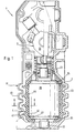
- a Load switch 1 is a pressure housing with two housing halves 11 and 12, which are made of insulating material and essentially are mirror images.
- halves 11 and 12 include a vacuum interrupter 2 and a switching mechanism 3 arranged.
- the way of arrangement and function of the vacuum interrupter 2 and Switch mechanism 3 corresponds to the known designs, which is why there is no detailed explanation becomes. It is essential that the vacuum interrupter 2 inside switching contacts, which by the Switching mechanism 3 can be closed or opened.
- the vacuum interrupter 2 has in addition to the movable Contact 21 a fixed contact 22 on the arranged opposite the movable contact 21 is.
- the vacuum interrupter 2 also has a housing 23 on that with metal end plates 24 and 25 is provided, which has a cylindrical housing middle part Complete 26.
- the middle housing part 26 is made of electrically insulating material.
- EPDM ethylene-propylene terpolymer
- the cuff 4 is there trained so that the edges of the two End plates 24 and 25 of the vacuum interrupter 2 engages.
- the dimensions of the cuff 4 are so chosen that tolerance deviations of the vacuum interrupter 2 can be compensated and the cuff 4 nevertheless under tension on the peripheral surface of the vacuum interrupter 2 is present. As a result, there is no continuous Air gap between the face plates 24 and 25 in front.
- the cuff 4 is in turn from the housing halves 11 and 12 of the load switch 1 gripped and biased. Due to the preload is also between the sleeve 4 and the assembled housing halves 11 and 12 no air gap in front of it that would roll over the tension between the end plates 24 and 25 of the Vacuum interrupter 2 would allow.
- the cuff has 4 ring-shaped screens 41, which in corresponding recesses in the housing halves 11 and 12 are included.
- the screens 41 are used in a known manner Way to extend the path (Creepage distance) along the surface.
- the cuff 4 also has four cutouts 42 which are arranged on the inner peripheral surface and have an annular shape. While closing the housing halves 11 and 12 is pressure on the cuff 4 exercised and since this is made of an elastomer material is produced, which is elastic but essentially the cutouts allow not compressible 42 evading the material of the cuff 4 into the free spaces thus created. On this will damage the cuff 4 prevents and a good seal of the interface between the sleeve 4 and the vacuum interrupter 2 reached.
- annular pocket 43 is also formed.
- Vacuum interrupters 2 relatively large length tolerances may have a length setting or positioning of the vacuum interrupter 2 in the load switch 1 necessary. The necessary deformation the cuff 4 in this end region enable, the annular pocket 43 serves as a chamber for volume compensation of the displaced material.
- the cuff has 4 also a sealing bead 44 with a thickening 45 on. These are each on the two assembly joints Housing halves 11 and 12 of the load switch 1 for sealing arranged against external influences.
- the Thickening 45 is in appropriately trained Indentations or grooves on the joint surfaces of the housing halves 11 and 12 added and when closing the Housing halves 11 and 12 squeezed.
- the sealing bead 44 with the thickening 45 has a length that corresponds essentially to the total length of the cuff 4. But it can also be used in the entire assembly joint area the housing halves 11 and 12 in one piece with the Cuff 4 as a round cord for sealing the pressure housing be trained.
- the load switch used as switch disconnector and in series with one visible separation distance arranged.
- One is for the main current path designed in parallel to the vacuum interrupter and one with this in Series connected auxiliary switching point, whereby the vacuum tube with the switch disconnector switched on is relieved.
- To switch off the load break switch the main contact is first opened in a known manner, whereby the voltage is completely across the vacuum interrupter 2 is directed. Then be the contacts 21 and 22 of the vacuum interrupter 2 separated and the connection is completely broken, without arcing in the circuit breaker 1 can train.
- the dimensions and shape of the cuff 4 can vary depending on the design and type of the vacuum interrupter 2. It is essential in any case that the Sleeve 4 rests against the vacuum interrupter 2 in such a way that no air gap between them is possible.
- the cuff 4 does not have to be formed with screens 41 but can also be a different one or have a smooth outer peripheral surface, if the Safety of the load switch 1 e.g. due to minor existing voltages.
- the recesses 42 in the cuff 4 have shown example semicircular cross sections and are in four places around the vacuum interrupter 2 educated. Both the shape and the number of annular recesses 42 can deviate from this. Furthermore, it is also possible to use the cutouts 42 instead the shown embodiment with an annular Shape at points on the inner circumferential surface to provide the cuff 4.
- the pocket 43 in the cuff 4 can also be on both End faces may be provided. Furthermore, can also the shape and number of pocket 43 in a similar manner Vary as in the recesses 42.
- the cuff 4 can be connected in any way can be used with vacuum interrupters 2 which also have switching elements other than switch disconnectors includes. It is also used in circuit breakers and the like conceivable.
- the pressure housing can also consist of more than two housing parts exist, the number of sealing beads 44th is adapted to the number of assembly joints.
- the invention thus creates a load switch 1 for voltages in the kV range with a vacuum interrupter 2, which with a made of elastomer material high dielectric strength sleeve 4 is gripped without gaps.
- the cuff 4 is in turn through the housing halves 11 and 12 of the Load switch 1 clamped.
Landscapes
- High-Tension Arc-Extinguishing Switches Without Spraying Means (AREA)
- Electrophonic Musical Instruments (AREA)
- Keying Circuit Devices (AREA)
- Axle Suspensions And Sidecars For Cycles (AREA)
- Gas-Insulated Switchgears (AREA)
- Oscillators With Electromechanical Resonators (AREA)
- Power Steering Mechanism (AREA)
- Driving Mechanisms And Operating Circuits Of Arc-Extinguishing High-Tension Switches (AREA)
- Thermally Actuated Switches (AREA)
- Electric Clocks (AREA)
Description
- Fig. 1
- eine Schnittdarstellung eines erfindungsgemäßen Lastschalters, wobei auf der linken Seite der Hauptachse ein Schnitt in der Trennebene des Druckgehäuses und rechts von der Hauptachse ein Schnitt in einer anderen Ebene durch eine Gehäusehälfte des Druckgehäuses dargestellt ist; und
- Fig. 2
- eine vereinfachte Schnittdarstellung gemäß der Linie A-A in Fig. 1.
Claims (12)
- Lastschalter (1) für Spannungen oberhalb 1 kV, mit einer Vakuum-Schaltkammer (2), deren Kontakte (21, 22) mittels einer Schaltmechanik (3) geschlossen oder geöffnet werden, wobei die Vakuum-Schaltkammer (2) ein die im Vakuum liegenden Schaltkontakte umschließendes Gehäuse (23) mit metallischen Stirnplatten (24, 25) und einen zylinderförmigen Gehäusemittelteil (26) aus elektrisch isolierendem Material aufweist, das von einer Schicht aus einem dielektrischen Material umgeben ist, welche die Ränder der beiden Stirnplatten (24, 25) hintergreift, wobei an der Außenseite der dielektrischen Schicht ein komplementär ausgebildeter Mantel aus Isolierstoff vorgesehen ist, welcher den Außenumfang der dielektrischen Schicht unter Druck setzt,
dadurch gekennzeichnet,
daß die dielektrische Schicht von einer vorgefertigten Manschette (4) gebildet ist, die aus einem Elastomermaterial mit hoher dielektrischer Festigkeit besteht, welches durch ein als Mantel dienendes Druckgehäuse (11, 12) spaltfrei an das Gehäuse (23) angepreßt ist. - Lastschalter nach Anspruch 1, dadurch gekennzeichnet, daß die Abmessungen der Manschette (4) derart gewählt sind, daß die Manschette (4) mit Vorspannung am Umfang der Vakuum-Schaltkammer (2) anliegt.
- Lastschalter nach Anspruch 2, dadurch gekennzeichnet, daß die Manschette (4) wenigstens einen in Achsrichtung des Druckgehäuses (11, 12) verlaufenden Dichtwulst (44) aufweist, der in der Montagefuge des Druckgehäuses (11, 12) zu liegen kommt.
- Lastschalter nach Anspruch 3, dadurch gekennzeichnet, daß der Dichtwulst (44) eine Verdickung (45) aufweist, die in der Montagefuge des Druckgehäuses (11, 12) verquetschbar ist.
- Lastschalter nach einem der Ansprüche 1 bis 4, dadurch gekennzeichnet, daß am Außenumfang der Manschette (4) im wesentlichen parallel zu den Stirnplatten (24, 25) der Vakumm-Schaltkammer (2) vorspringende und umlaufende Schirme (41) angeordnet sind.
- Lastschalter nach einem der Ansprüche 1 bis 5, dadurch gekennzeichnet, daß die Manschette (4) wenigstens eine Aussparung (42) zur Aufnahme von bei der Druckbelastung durch das Druckgehäuse (11, 12) verdrängtem Material aufweist.
- Lastschalter nach Anspruch 6, dadurch gekennzeichnet, daß die wenigstens eine Aussparung (42) als umlaufende Ringnut ausgebildet sind.
- Lastschalter nach einem der Ansprüche 1 bis 7, dadurch gekennzeichnet, daß an der Manschette (4) im Bereich der Stirnplatte (25) und/oder der Stirnplatte (24) wenigstens eine Tasche (43) ausgebildet ist.
- Lastschalter nach Anspruch 8, dadurch gekennzeichnet, daß die wenigstens eine Tasche (43) als ringförmige Nut ausgebildet ist.
- Lastschalter nach einem der Ansprüche 1 bis 9, dadurch gekennzeichnet, daß die Manschette (4) aus Silikonkautschuk oder aus EPDM (Ethylen-Propylen-Terpolymer) ausgebildet ist.
- Lastschalter nach einem der Ansprüche 1 bis 10, dadurch gekennzeichnet, daß er als Lasttrennschalter ausgebildet ist, bei dem in Reihenschaltung zur Vakuum-Schaltkammer eine sichtbare Trennstrecke angeordnet ist.
- Lastschalter nach einem der Ansprüche 1 bis 11, dadurch gekennzeichnet, daß parallel zur Vakuum-Schaltkammer oder parallel zur Reihenschaltung Vakuum-Schaltkammer/ sichtbare Trennstrecke im eingeschalteten Zustand des Lastschalters eine Strombahn für hohe Dauerstrom-Belastbarkeit geschaltet ist.
Priority Applications (1)
| Application Number | Priority Date | Filing Date | Title |
|---|---|---|---|
| SI9730071T SI920705T2 (en) | 1996-08-26 | 1997-08-25 | Load interrupter switch |
Applications Claiming Priority (3)
| Application Number | Priority Date | Filing Date | Title |
|---|---|---|---|
| DE19634451 | 1996-08-26 | ||
| DE19634451A DE19634451C1 (de) | 1996-08-26 | 1996-08-26 | Lastschalter |
| PCT/EP1997/004617 WO1998009310A1 (de) | 1996-08-26 | 1997-08-25 | Lastschalter |
Publications (3)
| Publication Number | Publication Date |
|---|---|
| EP0920705A1 EP0920705A1 (de) | 1999-06-09 |
| EP0920705B1 true EP0920705B1 (de) | 2000-04-19 |
| EP0920705B2 EP0920705B2 (de) | 2003-05-14 |
Family
ID=7803719
Family Applications (1)
| Application Number | Title | Priority Date | Filing Date |
|---|---|---|---|
| EP97944787A Expired - Lifetime EP0920705B2 (de) | 1996-08-26 | 1997-08-25 | Lastschalter |
Country Status (17)
| Country | Link |
|---|---|
| EP (1) | EP0920705B2 (de) |
| AT (1) | ATE191990T1 (de) |
| AU (1) | AU4618397A (de) |
| CA (1) | CA2263881C (de) |
| CZ (1) | CZ288889B6 (de) |
| DE (2) | DE19634451C1 (de) |
| DK (1) | DK0920705T4 (de) |
| ES (1) | ES2144880T5 (de) |
| GR (1) | GR3033287T3 (de) |
| HU (1) | HU222705B1 (de) |
| PL (1) | PL187251B1 (de) |
| PT (1) | PT920705E (de) |
| RS (1) | RS49698B (de) |
| RU (1) | RU2188474C2 (de) |
| SK (1) | SK282723B6 (de) |
| TR (1) | TR199900436T2 (de) |
| WO (1) | WO1998009310A1 (de) |
Families Citing this family (8)
| Publication number | Priority date | Publication date | Assignee | Title |
|---|---|---|---|---|
| US6130394A (en) * | 1996-08-26 | 2000-10-10 | Elektrotechnische Weke Fritz Driescher & Sohne GmbH | Hermetically sealed vacuum load interrupter switch with flashover features |
| DE19712182A1 (de) * | 1997-03-22 | 1998-09-24 | Abb Patent Gmbh | Vakuumkammer |
| DE19906972B4 (de) * | 1999-02-19 | 2008-04-30 | Abb Ag | Schalterpolteil mit Vakuumschaltkammer |
| DE19918077C1 (de) * | 1999-04-21 | 2000-11-09 | Driescher Eltech Werk | Lastschalter |
| FR2794280B1 (fr) * | 1999-05-28 | 2001-07-20 | Alstom | Disjoncteur a moyenne tension a coupure dans le vide comportant un boitier de protection par pole |
| DE102004006476B4 (de) * | 2004-02-04 | 2006-02-09 | Siemens Ag | Lasttrennschalter |
| RU2317609C1 (ru) * | 2006-10-23 | 2008-02-20 | ОАО "Карпинский электромашиностроительный завод" | Вакуумный выключатель |
| FR3073663A1 (fr) * | 2017-11-16 | 2019-05-17 | Schneider Electric Industries Sas | Pole de coupure pour appareil electrique de coupure |
Family Cites Families (9)
| Publication number | Priority date | Publication date | Assignee | Title |
|---|---|---|---|---|
| GB1191664A (en) * | 1966-06-07 | 1970-05-13 | Reyrolle & Company Ltd | Improvements relating to Vacuum Switches |
| US3594525A (en) * | 1969-04-21 | 1971-07-20 | Gen Electric | Common parallel operating means for series-connected, laterally offset vacuum switches |
| US3671696A (en) * | 1970-11-16 | 1972-06-20 | Allis Chalmers Mfg Co | Vacuum interrupter shunted with mechanical switch |
| DE2322372C3 (de) † | 1973-04-30 | 1980-06-04 | Siemens Ag, 1000 Berlin Und 8000 Muenchen | Mehrpoliges Vakuumschaltgerät mit isolierstoffgekapselten Schaltgefäßen |
| US4088859A (en) * | 1977-02-23 | 1978-05-09 | Westinghouse Electric Corp. | Normal open low voltage vacuum shorting switch |
| US4393286A (en) * | 1978-08-24 | 1983-07-12 | Tokyo Shibaura Denki Kabushiki Kaisha | Vacuum circuit breakers |
| JPS5812230A (ja) * | 1981-07-16 | 1983-01-24 | 富士電機株式会社 | 断路器付真空負荷開閉器 |
| FR2698481B1 (fr) * | 1992-11-26 | 1995-02-17 | Soule Sa | Système de coupure de ligne électrique comportant un interrupteur sous atmosphère contrôlée. |
| DE9314754U1 (de) * | 1993-09-27 | 1994-03-03 | Siemens AG, 80333 München | Vakuumschaltröhre mit einer gegen Innendruck beständigen Kapselung |
-
1996
- 1996-08-26 DE DE19634451A patent/DE19634451C1/de not_active Expired - Lifetime
-
1997
- 1997-08-25 CA CA002263881A patent/CA2263881C/en not_active Expired - Lifetime
- 1997-08-25 CZ CZ1999585A patent/CZ288889B6/cs not_active IP Right Cessation
- 1997-08-25 PT PT97944787T patent/PT920705E/pt unknown
- 1997-08-25 PL PL97331997A patent/PL187251B1/pl unknown
- 1997-08-25 RU RU99105735/09A patent/RU2188474C2/ru active
- 1997-08-25 AT AT97944787T patent/ATE191990T1/de active
- 1997-08-25 DK DK97944787T patent/DK0920705T4/da active
- 1997-08-25 ES ES97944787T patent/ES2144880T5/es not_active Expired - Lifetime
- 1997-08-25 AU AU46183/97A patent/AU4618397A/en not_active Abandoned
- 1997-08-25 WO PCT/EP1997/004617 patent/WO1998009310A1/de not_active Ceased
- 1997-08-25 DE DE59701481T patent/DE59701481D1/de not_active Expired - Lifetime
- 1997-08-25 SK SK238-99A patent/SK282723B6/sk not_active IP Right Cessation
- 1997-08-25 RS YUP-102/99A patent/RS49698B/sr unknown
- 1997-08-25 EP EP97944787A patent/EP0920705B2/de not_active Expired - Lifetime
- 1997-08-25 TR TR1999/00436T patent/TR199900436T2/xx unknown
- 1997-08-25 HU HU9903117A patent/HU222705B1/hu active IP Right Grant
-
2000
- 2000-04-20 GR GR20000400964T patent/GR3033287T3/el unknown
Also Published As
| Publication number | Publication date |
|---|---|
| GR3033287T3 (en) | 2000-09-29 |
| PT920705E (pt) | 2000-10-31 |
| DK0920705T3 (da) | 2000-09-25 |
| HK1017768A1 (en) | 1999-11-26 |
| HUP9903117A2 (hu) | 2000-02-28 |
| RU2188474C2 (ru) | 2002-08-27 |
| CA2263881C (en) | 2006-11-28 |
| SK282723B6 (sk) | 2002-11-06 |
| YU10299A (en) | 1999-11-22 |
| WO1998009310A1 (de) | 1998-03-05 |
| PL331997A1 (en) | 1999-08-16 |
| RS49698B (sr) | 2007-12-31 |
| DE59701481D1 (de) | 2000-05-25 |
| ES2144880T5 (es) | 2004-02-16 |
| PL187251B1 (pl) | 2004-06-30 |
| DE19634451C1 (de) | 1998-01-29 |
| ES2144880T3 (es) | 2000-06-16 |
| DK0920705T4 (da) | 2003-06-30 |
| CZ288889B6 (cs) | 2001-09-12 |
| CA2263881A1 (en) | 1998-03-05 |
| AU4618397A (en) | 1998-03-19 |
| CZ58599A3 (cs) | 1999-07-14 |
| HU222705B1 (hu) | 2003-09-29 |
| TR199900436T2 (xx) | 1999-05-21 |
| ATE191990T1 (de) | 2000-05-15 |
| SK23899A3 (en) | 2000-03-13 |
| EP0920705A1 (de) | 1999-06-09 |
| EP0920705B2 (de) | 2003-05-14 |
| HUP9903117A3 (en) | 2002-03-28 |
Similar Documents
| Publication | Publication Date | Title |
|---|---|---|
| DE69624901T2 (de) | Membran-Abdichtung für Hochspannungsschalter-Umgebung | |
| DE112009005167B4 (de) | Schaltanlage | |
| EP2702597B1 (de) | Überspannungsableiter | |
| DE69527833T2 (de) | Hochleistungsschalter mit bedienungsgestaenge und konische durchfuehrung | |
| DE69802414T2 (de) | Elektrische verbindungsvorrichtung mit einem fluidischen isolierstoff | |
| DE1193568B (de) | Durchfuehrung fuer elektrische Geraete, insbesondere Leistungsschalter, die ein gas-foermiges Isoliermittel enthalten | |
| EP0920705B1 (de) | Lastschalter | |
| DE19902835A1 (de) | Hochspannungsleistungsschalter mit einer Isolierdüse | |
| WO2004093276A2 (de) | Erdungsschalter mit einem bewegbaren kontaktstück | |
| DE69111571T2 (de) | Mehrpoliger Drehschalter. | |
| CH668664A5 (de) | Gasisolierter lasttrenner. | |
| EP0678952B1 (de) | Trenner für eine metallgekapselte gasisolierte Hochspannungsschaltanlage | |
| WO2008077878A1 (de) | Isolationsgehäuse | |
| EP0545508B1 (de) | Metallgekapselte gasisolierte Schaltanlage mit einem Kabelanschlussgehäuse | |
| DE3513908C2 (de) | Freiluftschaltgerät für Hochspannungsschaltanlagen | |
| EP3566238B1 (de) | Überspannungsableiter und herstellungsverfahren für einen überspannungsableiter | |
| EP1187157B1 (de) | Trennschalter | |
| DE2828773A1 (de) | Autopneumatischer druckgasschalter | |
| DE60104946T2 (de) | Treibstange für einen Hochspannungsschalter | |
| EP0703593B1 (de) | Polsäule eines elektrischen Leistungsschalters | |
| DE1438244A1 (de) | UEberspannungsableiter | |
| DE102007027411A1 (de) | Überspannungsableiteranordnung | |
| DE102020205608A1 (de) | Hochspannungsleistungsschalter und Verfahren zum Isolieren wenigstens einer Vakuumschaltröhre mit Kunststoffschaum | |
| WO2014048711A1 (de) | Überspannungsableiter | |
| DE2541446A1 (de) | Hochspannungs-lastschalter |
Legal Events
| Date | Code | Title | Description |
|---|---|---|---|
| PUAI | Public reference made under article 153(3) epc to a published international application that has entered the european phase |
Free format text: ORIGINAL CODE: 0009012 |
|
| 17P | Request for examination filed |
Effective date: 19990319 |
|
| AK | Designated contracting states |
Kind code of ref document: A1 Designated state(s): AT BE CH DE DK ES FI FR GB GR IE IT LI LU MC NL PT SE |
|
| AX | Request for extension of the european patent |
Free format text: AL PAYMENT 19990319;LT PAYMENT 19990319;LV PAYMENT 19990319;RO PAYMENT 19990319;SI PAYMENT 19990319 |
|
| GRAG | Despatch of communication of intention to grant |
Free format text: ORIGINAL CODE: EPIDOS AGRA |
|
| 17Q | First examination report despatched |
Effective date: 19991214 |
|
| GRAG | Despatch of communication of intention to grant |
Free format text: ORIGINAL CODE: EPIDOS AGRA |
|
| GRAH | Despatch of communication of intention to grant a patent |
Free format text: ORIGINAL CODE: EPIDOS IGRA |
|
| GRAH | Despatch of communication of intention to grant a patent |
Free format text: ORIGINAL CODE: EPIDOS IGRA |
|
| GRAA | (expected) grant |
Free format text: ORIGINAL CODE: 0009210 |
|
| AK | Designated contracting states |
Kind code of ref document: B1 Designated state(s): AT BE CH DE DK ES FI FR GB GR IE IT LI LU MC NL PT SE |
|
| AX | Request for extension of the european patent |
Free format text: AL PAYMENT 19990319;LT PAYMENT 19990319;LV PAYMENT 19990319;RO PAYMENT 19990319;SI PAYMENT 19990319 |
|
| REF | Corresponds to: |
Ref document number: 191990 Country of ref document: AT Date of ref document: 20000515 Kind code of ref document: T |
|
| REG | Reference to a national code |
Ref country code: CH Ref legal event code: NV Representative=s name: ISLER & PEDRAZZINI AG Ref country code: CH Ref legal event code: EP |
|
| REF | Corresponds to: |
Ref document number: 59701481 Country of ref document: DE Date of ref document: 20000525 |
|
| REG | Reference to a national code |
Ref country code: IE Ref legal event code: FG4D Free format text: GERMAN |
|
| ET | Fr: translation filed | ||
| GBT | Gb: translation of ep patent filed (gb section 77(6)(a)/1977) |
Effective date: 20000522 |
|
| REG | Reference to a national code |
Ref country code: ES Ref legal event code: FG2A Ref document number: 2144880 Country of ref document: ES Kind code of ref document: T3 |
|
| ITF | It: translation for a ep patent filed | ||
| REG | Reference to a national code |
Ref country code: DK Ref legal event code: T3 |
|
| REG | Reference to a national code |
Ref country code: PT Ref legal event code: SC4A Free format text: AVAILABILITY OF NATIONAL TRANSLATION Effective date: 20000714 |
|
| PLBE | No opposition filed within time limit |
Free format text: ORIGINAL CODE: 0009261 |
|
| PLBQ | Unpublished change to opponent data |
Free format text: ORIGINAL CODE: EPIDOS OPPO |
|
| PLAA | Information modified related to event that no opposition was filed |
Free format text: ORIGINAL CODE: 0009299DELT |
|
| PLBI | Opposition filed |
Free format text: ORIGINAL CODE: 0009260 |
|
| PLBF | Reply of patent proprietor to notice(s) of opposition |
Free format text: ORIGINAL CODE: EPIDOS OBSO |
|
| 26N | No opposition filed | ||
| 26 | Opposition filed |
Opponent name: HOLEC HOLLAND N.V Effective date: 20010119 |
|
| D26N | No opposition filed (deleted) | ||
| NLR1 | Nl: opposition has been filed with the epo |
Opponent name: HOLEC HOLLAND N.V |
|
| PLBF | Reply of patent proprietor to notice(s) of opposition |
Free format text: ORIGINAL CODE: EPIDOS OBSO |
|
| DX | Miscellaneous (deleted) | ||
| REG | Reference to a national code |
Ref country code: GB Ref legal event code: IF02 |
|
| PLAW | Interlocutory decision in opposition |
Free format text: ORIGINAL CODE: EPIDOS IDOP |
|
| PLAW | Interlocutory decision in opposition |
Free format text: ORIGINAL CODE: EPIDOS IDOP |
|
| PUAH | Patent maintained in amended form |
Free format text: ORIGINAL CODE: 0009272 |
|
| STAA | Information on the status of an ep patent application or granted ep patent |
Free format text: STATUS: PATENT MAINTAINED AS AMENDED |
|
| 27A | Patent maintained in amended form |
Effective date: 20030514 |
|
| AK | Designated contracting states |
Designated state(s): AT BE CH DE DK ES FI FR GB GR IE IT LI LU MC NL PT SE |
|
| AX | Request for extension of the european patent |
Extension state: AL LT LV RO SI |
|
| REG | Reference to a national code |
Ref country code: CH Ref legal event code: AEN Free format text: AUFRECHTERHALTUNG DES PATENTES IN GEAENDERTER FORM |
|
| REG | Reference to a national code |
Ref country code: DK Ref legal event code: EBP |
|
| NLR2 | Nl: decision of opposition |
Effective date: 20030514 |
|
| NLR3 | Nl: receipt of modified translations in the netherlands language after an opposition procedure | ||
| REG | Reference to a national code |
Ref country code: SE Ref legal event code: RPEO |
|
| REG | Reference to a national code |
Ref country code: GR Ref legal event code: EP Ref document number: 20030403189 Country of ref document: GR |
|
| REG | Reference to a national code |
Ref country code: ES Ref legal event code: DC2A Date of ref document: 20030806 Kind code of ref document: T5 |
|
| ET3 | Fr: translation filed ** decision concerning opposition | ||
| REG | Reference to a national code |
Ref country code: SI Ref legal event code: IF |
|
| PGFP | Annual fee paid to national office [announced via postgrant information from national office to epo] |
Ref country code: PT Payment date: 20050719 Year of fee payment: 9 |
|
| PGFP | Annual fee paid to national office [announced via postgrant information from national office to epo] |
Ref country code: FR Payment date: 20050728 Year of fee payment: 9 |
|
| PGFP | Annual fee paid to national office [announced via postgrant information from national office to epo] |
Ref country code: MC Payment date: 20050808 Year of fee payment: 9 |
|
| PGFP | Annual fee paid to national office [announced via postgrant information from national office to epo] |
Ref country code: BE Payment date: 20050810 Year of fee payment: 9 |
|
| PGFP | Annual fee paid to national office [announced via postgrant information from national office to epo] |
Ref country code: LU Payment date: 20050811 Year of fee payment: 9 |
|
| PGFP | Annual fee paid to national office [announced via postgrant information from national office to epo] |
Ref country code: IE Payment date: 20050812 Year of fee payment: 9 |
|
| PGFP | Annual fee paid to national office [announced via postgrant information from national office to epo] |
Ref country code: GB Payment date: 20050824 Year of fee payment: 9 |
|
| PG25 | Lapsed in a contracting state [announced via postgrant information from national office to epo] |
Ref country code: IE Free format text: LAPSE BECAUSE OF NON-PAYMENT OF DUE FEES Effective date: 20060825 |
|
| PG25 | Lapsed in a contracting state [announced via postgrant information from national office to epo] |
Ref country code: MC Free format text: LAPSE BECAUSE OF NON-PAYMENT OF DUE FEES Effective date: 20060831 Ref country code: BE Free format text: LAPSE BECAUSE OF NON-PAYMENT OF DUE FEES Effective date: 20060831 |
|
| PG25 | Lapsed in a contracting state [announced via postgrant information from national office to epo] |
Ref country code: PT Free format text: LAPSE BECAUSE OF NON-PAYMENT OF DUE FEES Effective date: 20070226 |
|
| REG | Reference to a national code |
Ref country code: PT Ref legal event code: MM4A Free format text: LAPSE DUE TO NON-PAYMENT OF FEES Effective date: 20070226 |
|
| GBPC | Gb: european patent ceased through non-payment of renewal fee |
Effective date: 20060825 |
|
| LTLA | Lt: lapse of european patent or patent extension |
Effective date: 20060825 |
|
| REG | Reference to a national code |
Ref country code: IE Ref legal event code: MM4A |
|
| REG | Reference to a national code |
Ref country code: FR Ref legal event code: ST Effective date: 20070430 |
|
| REG | Reference to a national code |
Ref country code: CH Ref legal event code: PCAR Free format text: ISLER & PEDRAZZINI AG;POSTFACH 1772;8027 ZUERICH (CH) |
|
| PG25 | Lapsed in a contracting state [announced via postgrant information from national office to epo] |
Ref country code: GB Free format text: LAPSE BECAUSE OF NON-PAYMENT OF DUE FEES Effective date: 20060825 |
|
| BERE | Be: lapsed |
Owner name: ELEKTROTECHNISCHE WERKE FRITZ *DRIESCHER & SOHNE G Effective date: 20060831 |
|
| PGFP | Annual fee paid to national office [announced via postgrant information from national office to epo] |
Ref country code: NL Payment date: 20070831 Year of fee payment: 11 |
|
| PG25 | Lapsed in a contracting state [announced via postgrant information from national office to epo] |
Ref country code: FR Free format text: LAPSE BECAUSE OF NON-PAYMENT OF DUE FEES Effective date: 20060831 |
|
| PG25 | Lapsed in a contracting state [announced via postgrant information from national office to epo] |
Ref country code: LU Free format text: LAPSE BECAUSE OF NON-PAYMENT OF DUE FEES Effective date: 20060825 |
|
| NLV4 | Nl: lapsed or anulled due to non-payment of the annual fee |
Effective date: 20090301 |
|
| PG25 | Lapsed in a contracting state [announced via postgrant information from national office to epo] |
Ref country code: NL Free format text: LAPSE BECAUSE OF NON-PAYMENT OF DUE FEES Effective date: 20090301 |
|
| PGFP | Annual fee paid to national office [announced via postgrant information from national office to epo] |
Ref country code: CH Payment date: 20160811 Year of fee payment: 20 Ref country code: IT Payment date: 20160713 Year of fee payment: 20 Ref country code: DE Payment date: 20160809 Year of fee payment: 20 Ref country code: FI Payment date: 20160805 Year of fee payment: 20 Ref country code: DK Payment date: 20160805 Year of fee payment: 20 |
|
| PGFP | Annual fee paid to national office [announced via postgrant information from national office to epo] |
Ref country code: SE Payment date: 20160811 Year of fee payment: 20 Ref country code: AT Payment date: 20160826 Year of fee payment: 20 Ref country code: GR Payment date: 20160727 Year of fee payment: 20 |
|
| PGFP | Annual fee paid to national office [announced via postgrant information from national office to epo] |
Ref country code: ES Payment date: 20160718 Year of fee payment: 20 |
|
| REG | Reference to a national code |
Ref country code: DE Ref legal event code: R071 Ref document number: 59701481 Country of ref document: DE |
|
| REG | Reference to a national code |
Ref country code: DK Ref legal event code: EUP Effective date: 20170825 |
|
| REG | Reference to a national code |
Ref country code: CH Ref legal event code: PL |
|
| REG | Reference to a national code |
Ref country code: SE Ref legal event code: EUG |
|
| REG | Reference to a national code |
Ref country code: AT Ref legal event code: MK07 Ref document number: 191990 Country of ref document: AT Kind code of ref document: T Effective date: 20170825 |
|
| REG | Reference to a national code |
Ref country code: ES Ref legal event code: FD2A Effective date: 20171201 |
|
| PG25 | Lapsed in a contracting state [announced via postgrant information from national office to epo] |
Ref country code: ES Free format text: LAPSE BECAUSE OF EXPIRATION OF PROTECTION Effective date: 20170826 |