EP0919771B1 - Procédé de combustion pour matières solides sur une grille coulissante refroidie par eau, ainsi que barreau de grille et grille pour la mise en oeuvre du procédé - Google Patents
Procédé de combustion pour matières solides sur une grille coulissante refroidie par eau, ainsi que barreau de grille et grille pour la mise en oeuvre du procédé Download PDFInfo
- Publication number
- EP0919771B1 EP0919771B1 EP98810971A EP98810971A EP0919771B1 EP 0919771 B1 EP0919771 B1 EP 0919771B1 EP 98810971 A EP98810971 A EP 98810971A EP 98810971 A EP98810971 A EP 98810971A EP 0919771 B1 EP0919771 B1 EP 0919771B1
- Authority
- EP
- European Patent Office
- Prior art keywords
- grate
- primary air
- plates
- combustion
- openings
- Prior art date
- Legal status (The legal status is an assumption and is not a legal conclusion. Google has not performed a legal analysis and makes no representation as to the accuracy of the status listed.)
- Expired - Lifetime
Links
- 238000002485 combustion reaction Methods 0.000 title claims abstract description 62
- 238000000034 method Methods 0.000 title claims description 13
- 239000011343 solid material Substances 0.000 title 1
- 239000000463 material Substances 0.000 claims description 21
- 239000007787 solid Substances 0.000 claims description 9
- 229910000831 Steel Inorganic materials 0.000 claims description 4
- 239000010959 steel Substances 0.000 claims description 4
- 239000000498 cooling water Substances 0.000 claims description 2
- 238000009841 combustion method Methods 0.000 abstract 1
- 239000004449 solid propellant Substances 0.000 abstract 1
- 238000010304 firing Methods 0.000 description 19
- 239000003546 flue gas Substances 0.000 description 11
- UGFAIRIUMAVXCW-UHFFFAOYSA-N Carbon monoxide Chemical compound [O+]#[C-] UGFAIRIUMAVXCW-UHFFFAOYSA-N 0.000 description 9
- XEEYBQQBJWHFJM-UHFFFAOYSA-N Iron Chemical compound [Fe] XEEYBQQBJWHFJM-UHFFFAOYSA-N 0.000 description 8
- 239000000428 dust Substances 0.000 description 5
- JEIPFZHSYJVQDO-UHFFFAOYSA-N iron(III) oxide Inorganic materials O=[Fe]O[Fe]=O JEIPFZHSYJVQDO-UHFFFAOYSA-N 0.000 description 5
- 239000002893 slag Substances 0.000 description 5
- QVGXLLKOCUKJST-UHFFFAOYSA-N atomic oxygen Chemical compound [O] QVGXLLKOCUKJST-UHFFFAOYSA-N 0.000 description 4
- 238000001816 cooling Methods 0.000 description 4
- 238000010586 diagram Methods 0.000 description 4
- 229910052742 iron Inorganic materials 0.000 description 4
- 239000001301 oxygen Substances 0.000 description 4
- 229910052760 oxygen Inorganic materials 0.000 description 4
- 239000007789 gas Substances 0.000 description 3
- 239000002184 metal Substances 0.000 description 3
- 229910052751 metal Inorganic materials 0.000 description 3
- 239000010813 municipal solid waste Substances 0.000 description 3
- 238000004056 waste incineration Methods 0.000 description 3
- XLYOFNOQVPJJNP-UHFFFAOYSA-N water Substances O XLYOFNOQVPJJNP-UHFFFAOYSA-N 0.000 description 3
- 239000002956 ash Substances 0.000 description 2
- POIUWJQBRNEFGX-XAMSXPGMSA-N cathelicidin Chemical compound C([C@@H](C(=O)N[C@@H](CCCNC(N)=N)C(=O)N[C@@H](CCCCN)C(=O)N[C@@H](CO)C(=O)N[C@@H](CCCCN)C(=O)N[C@@H](CCC(O)=O)C(=O)N[C@@H](CCCCN)C(=O)N[C@@H]([C@@H](C)CC)C(=O)NCC(=O)N[C@@H](CCCCN)C(=O)N[C@@H](CCC(O)=O)C(=O)N[C@@H](CC=1C=CC=CC=1)C(=O)N[C@@H](CCCCN)C(=O)N[C@@H](CCCNC(N)=N)C(=O)N[C@@H]([C@@H](C)CC)C(=O)N[C@@H](C(C)C)C(=O)N[C@@H](CCC(N)=O)C(=O)N[C@@H](CCCNC(N)=N)C(=O)N[C@@H]([C@@H](C)CC)C(=O)N[C@@H](CCCCN)C(=O)N[C@@H](CC(O)=O)C(=O)N[C@@H](CC=1C=CC=CC=1)C(=O)N[C@@H](CC(C)C)C(=O)N[C@@H](CCCNC(N)=N)C(=O)N[C@@H](CC(N)=O)C(=O)N[C@@H](CC(C)C)C(=O)N[C@@H](C(C)C)C(=O)N1[C@@H](CCC1)C(=O)N[C@@H](CCCNC(N)=N)C(=O)N[C@@H]([C@@H](C)O)C(=O)N[C@@H](CCC(O)=O)C(=O)N[C@@H](CO)C(O)=O)NC(=O)[C@H](CC=1C=CC=CC=1)NC(=O)[C@H](CC(O)=O)NC(=O)CNC(=O)[C@H](CC(C)C)NC(=O)[C@@H](N)CC(C)C)C1=CC=CC=C1 POIUWJQBRNEFGX-XAMSXPGMSA-N 0.000 description 2
- 230000003247 decreasing effect Effects 0.000 description 2
- 238000009792 diffusion process Methods 0.000 description 2
- 239000010791 domestic waste Substances 0.000 description 2
- 239000010881 fly ash Substances 0.000 description 2
- 239000002245 particle Substances 0.000 description 2
- 230000035515 penetration Effects 0.000 description 2
- -1 sawdust Substances 0.000 description 2
- 206010010774 Constipation Diseases 0.000 description 1
- 206010012735 Diarrhoea Diseases 0.000 description 1
- 230000009286 beneficial effect Effects 0.000 description 1
- 230000015572 biosynthetic process Effects 0.000 description 1
- 239000003795 chemical substances by application Substances 0.000 description 1
- 239000000567 combustion gas Substances 0.000 description 1
- 238000010276 construction Methods 0.000 description 1
- 238000011109 contamination Methods 0.000 description 1
- 239000002826 coolant Substances 0.000 description 1
- 230000007423 decrease Effects 0.000 description 1
- 230000001627 detrimental effect Effects 0.000 description 1
- 238000006073 displacement reaction Methods 0.000 description 1
- 230000000694 effects Effects 0.000 description 1
- 230000002996 emotional effect Effects 0.000 description 1
- 230000003628 erosive effect Effects 0.000 description 1
- 239000002440 industrial waste Substances 0.000 description 1
- 238000009434 installation Methods 0.000 description 1
- 230000001788 irregular Effects 0.000 description 1
- 239000003077 lignite Substances 0.000 description 1
- 239000002906 medical waste Substances 0.000 description 1
- 239000000203 mixture Substances 0.000 description 1
- 238000013021 overheating Methods 0.000 description 1
- 238000006213 oxygenation reaction Methods 0.000 description 1
- 230000000149 penetrating effect Effects 0.000 description 1
- 230000035699 permeability Effects 0.000 description 1
- 230000000704 physical effect Effects 0.000 description 1
- 238000005488 sandblasting Methods 0.000 description 1
- 239000010801 sewage sludge Substances 0.000 description 1
- 239000002023 wood Substances 0.000 description 1
Images

Classifications
-
- F—MECHANICAL ENGINEERING; LIGHTING; HEATING; WEAPONS; BLASTING
- F23—COMBUSTION APPARATUS; COMBUSTION PROCESSES
- F23G—CREMATION FURNACES; CONSUMING WASTE PRODUCTS BY COMBUSTION
- F23G5/00—Incineration of waste; Incinerator constructions; Details, accessories or control therefor
- F23G5/002—Incineration of waste; Incinerator constructions; Details, accessories or control therefor characterised by their grates
-
- F—MECHANICAL ENGINEERING; LIGHTING; HEATING; WEAPONS; BLASTING
- F23—COMBUSTION APPARATUS; COMBUSTION PROCESSES
- F23H—GRATES; CLEANING OR RAKING GRATES
- F23H7/00—Inclined or stepped grates
- F23H7/06—Inclined or stepped grates with movable bars disposed parallel to direction of fuel feeding
- F23H7/08—Inclined or stepped grates with movable bars disposed parallel to direction of fuel feeding reciprocating along their axes
-
- F—MECHANICAL ENGINEERING; LIGHTING; HEATING; WEAPONS; BLASTING
- F23—COMBUSTION APPARATUS; COMBUSTION PROCESSES
- F23H—GRATES; CLEANING OR RAKING GRATES
- F23H1/00—Grates with solid bars
- F23H1/02—Grates with solid bars having provision for air supply or air preheating, e.g. air-supply or blast fittings which form a part of the grate structure or serve as supports
-
- F—MECHANICAL ENGINEERING; LIGHTING; HEATING; WEAPONS; BLASTING
- F23—COMBUSTION APPARATUS; COMBUSTION PROCESSES
- F23H—GRATES; CLEANING OR RAKING GRATES
- F23H11/00—Travelling-grates
- F23H11/12—Travelling-grates inclined travelling grates; Stepped travelling grates
-
- F—MECHANICAL ENGINEERING; LIGHTING; HEATING; WEAPONS; BLASTING
- F23—COMBUSTION APPARATUS; COMBUSTION PROCESSES
- F23H—GRATES; CLEANING OR RAKING GRATES
- F23H3/00—Grates with hollow bars
- F23H3/02—Grates with hollow bars internally cooled
-
- F—MECHANICAL ENGINEERING; LIGHTING; HEATING; WEAPONS; BLASTING
- F23—COMBUSTION APPARATUS; COMBUSTION PROCESSES
- F23L—SUPPLYING AIR OR NON-COMBUSTIBLE LIQUIDS OR GASES TO COMBUSTION APPARATUS IN GENERAL ; VALVES OR DAMPERS SPECIALLY ADAPTED FOR CONTROLLING AIR SUPPLY OR DRAUGHT IN COMBUSTION APPARATUS; INDUCING DRAUGHT IN COMBUSTION APPARATUS; TOPS FOR CHIMNEYS OR VENTILATING SHAFTS; TERMINALS FOR FLUES
- F23L1/00—Passages or apertures for delivering primary air for combustion
- F23L1/02—Passages or apertures for delivering primary air for combustion by discharging the air below the fire
-
- F—MECHANICAL ENGINEERING; LIGHTING; HEATING; WEAPONS; BLASTING
- F23—COMBUSTION APPARATUS; COMBUSTION PROCESSES
- F23H—GRATES; CLEANING OR RAKING GRATES
- F23H2700/00—Grates characterised by special features or applications
- F23H2700/009—Grates specially adapted for incinerators
-
- F—MECHANICAL ENGINEERING; LIGHTING; HEATING; WEAPONS; BLASTING
- F23—COMBUSTION APPARATUS; COMBUSTION PROCESSES
- F23H—GRATES; CLEANING OR RAKING GRATES
- F23H2900/00—Special features of combustion grates
- F23H2900/03021—Liquid cooled grates
Definitions
- the invention relates to a method for burning solids on a water-cooled Thrust combustion grate, such as that used in waste incineration plants Installation is coming. Furthermore, it is about a specific grate plate and one made of such Rust plates built up rust, as is necessary to carry out the process.
- the too burning solids can be a wide variety of types of solids, be it lignite, sawdust, wood and rubber chips, all sorts of residual goods, Industrial waste, sewage sludge, hospital or household waste or rubbish, etc. etc.
- the primary air is blown through from below the grate through the grate into the combustion bed.
- the primary air reaches the top of the grate through recesses in the cast grate bars on the side and / or in the head region. The primary air is conveyed through the grate by building up corresponding overpressures of the order of magnitude of approx.
- the grate plates then have primary air supply channels on, for example, primary air supply pipes passing through the grate plate, which can also taper towards the top, or are the primary air supply channels formed by recesses for the passage of primary air, so that the primary air that is, it can be conducted from below the grate through it onto its upper side.
- the grate plates that run across the width can no longer slag between individual Grate elements fall under the grate, as is the case with grate levels consisting of several loose parts adjacent grate bars is the case. This makes slag diarrhea practical prevented.
- a grate has become known, in which the grate bars each consist of two nested profiles are shaped so that the air flowing through the rods passes through the attached ones Longitudinal profiles flow horizontally and laterally.
- the air diverted in this way is not pure primary air, but primarily cooling air, and the grate is not water-cooled Thrust combustion grate.
- EP 0'019'652 A (SULZER AG), December 10, 1980 shows a grate for a fluidized bed firing, which consists of water flowing through, parallel to each other at a distance arranged pipes, which are welded to each other with an intermediate web are.
- the primary air flows through the intermediate webs through air arranged therein Slits or holes upwards and flows around cover plates.
- these are not on a thrust combustion grate, and especially not on a water-cooled thrust combustion grate realized and can not be transferred directly to one.
- a method for burning solids a water-cooled thrust combustion grate which is characterized by the fact that the primary air fed into the combustion bed through the water-cooled thrust combustion grate after flowing through the grate plates of the thrust combustion grate on guide elements strikes, which over the mouths placed in the front of the grate plates are arranged, and is deflected by each such guide element, so that the deflected primary air - in comparison with its speed in the direction of the Sliding grate surface emerging primary air flow - at a slower speed flows diffusely into the firing material.
- a grate plate for consisting of a water-cooled thrust combustion grate for burning solids from a flow-through hollow body with connection piece for the supply and discharge of Cooling water, as well as primary air supply channels penetrating the grate plate from bottom to top, which is characterized by the fact that on the front of the grate plate placed the mouths of the primary air supply ducts on the grate plate surface are arranged, on which the primary air emerging from the mouth is intended to encounter.
- Thrust combustion grates have stationary and movable grate levels made of grate plates or from a series of grate bars, the grate steps being stepped on one another lie on. These sliding combustion grates can be installed so that the combustion bed in the is essentially horizontal, or inclined, with inclinations of up to 20 degrees or more are common.
- EP-0'621'449 describes a water-cooled thrust combustion grate known. Its grate plates are made of sheet steel and form board-shaped hollow bodies that extend across the width of the entire grating track and through which water is passed as a cooling medium. Every second grate plate is movable and can therefore perform a stoking or transport stroke.
- the movable grate plates can be fired with their end face Push it onto the next lower grate plate.
- a push-back grate forms a somewhat wrong built-in, inclined staircase.
- the end faces of the Movable grate plates transport the one behind them in a rear grate Firing material back, after which it rolls down again in the direction of the tendency to rust.
- the movable grate plates i.e. between two stationary grate plates arranged grate plates are usually collectively back and forth in the direction of their inclination emotional. This ensures that the burning rubbish lying on the grate at a long dwell time of 45 to 120 minutes constantly rearranged and even on the grate is distributed.
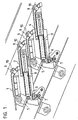
- FIG. 1 An advantageous construction of this thrust combustion grate with its essential elements can be seen in Figure 1, in which a portion of a thrust combustion grate is shown using a cross section.
- the grate consists of stairs Grate levels, which are each formed by a hollow, water-cooled grate plate 1,2,3,4. Every second grate level, in the figure the grate plates 2 and 4, is designed to be movable while the intermediate grate plates are suspended on cross tubes 5.
- the moveable Grate plates 2.4 are each laterally mounted on a roller 6 and lie with it Rear part on vertical rollers 7, which are arranged on the laterally delimiting planks are.
- Each movable grate plate 2.4 is from its own hydraulic piston-cylinder unit 8 driven.
- each grate plate open through the grate plate extending pipes 9 for the supply of primary air from the area below the Rust.
- These primary air supply pipes 9 open somewhat above the surface of the grate plate and have an elongated cross-section, as will be shown later becomes. In this way it has already been avoided that excessive amounts of these tubes Slag falls through.
- the mouths of these primary air pipes 9 or corresponding primary air supply channels are as shown here with guide elements 10 in the form of muzzle caps made of bow-shaped baffles that are simply welded onto the top of the grate plate are.
- the upper section of the baffles is V-shaped in cross section. The of The primary air jet hitting the bottom of these guide plates is therefore from the guide plates divided and distracted laterally.
- the bow-shaped baffles cover the mouth in the thrust direction of the grate, so that the fired material is guided around the baffles and does not directly cover the primary air outlets.
- FIG 2 is a part of the front edge of a grate plate with a design of the guide elements in the form of welded bow-shaped guide plates 10 in a perspective view shown.
- the mouth or nozzle caps 10 are welded in the form of the bow-shaped guide plates 10.
- These baffles 10 consist of sheet steel and form seen from the side, if they are welded on, a trapezoidal shape, the piece of sheet metal which the forms the upper side of the trapezoid, is V-shaped in cross section, which is indicated by a simple folding can be achieved.
- the one that hits from below becomes Primary air flow divided into two as indicated by the arrows and deflected laterally and thereby also swirled.
- the effect is that the air at a significantly reduced speed and penetrates diffusely into the kiln.
- the air passing through in a row arranged primary air orifices flows in, the combustion bed in its entirety Diffuse penetration wide, so that the atmospheric oxygen much more homogeneous than before Combustion is supplied.
- the bow-shaped Baffles can also form a semicircular arc, or one Angle welded onto the grate plate like a gable above the mouth.
- the Mounting direction can be chosen arbitrarily, so that the angular plane also in right angle to the direction of thrust. If the sheets as in the figure shown, this also ensures that the primary air supply openings are not clog.
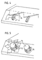
- Figure 3 shows a grate plate with a design of the guide elements in the form of welded flat baffles 12.
- This variant also fulfills the intended purpose, namely the deflection of the primary air and its diffusion, which in turn is indicated by arrows is.
- These flat bars 12 can serve a further purpose. They seem namely as barbs and take each time the movable plates are pushed forward the firing material lying in front of the area of the flat iron 12 while pulling it back release this again and then the primary air flows back to the flat iron 12 and it cools.
- FIG. 4 shows a further variant for a guide element, in this case a sawtooth-shaped one Sheet 13, similar to the shape of a cutter bar knife, across the width of the grate on the The front edge of the grate plate is welded on.
- the saw teeth each protrude above a nozzle the primary air supply, so that the emerging primary air flow onto one sawtooth each strikes and is deflected by this towards the front and the two sides.
- FIG. 5 shows an embodiment with screwed-on orifice caps 14.
- the primary air supply ducts or pipes are circular in this case and the pipe openings, which protrude slightly from the ros have an external thread.
- the nozzle cap 14 is screwed onto this.
- These nozzle caps 14 are standard fittings with hexagonal outer shape, which are used for this purpose be provided with radial bores 15.
- the fittings are only a small one Part of their thread screwed on, so that the primary air is unhindered by the radial Holes 15 can emerge. It is therefore after the pipe mouth of the fittings deflected and radially flows out through the six holes shown in the example, whereby it diffuses on all sides into the surrounding firing material, as indicated by the arrows. Clogging of the mouths arranged all around is due to the relative movement of the Mouth and nozzle caps 14 to the transported firing material impossible.
- Such nozzle caps can of course also have other shapes and are welded on instead of being screwed on.
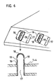
- FIG. 6 shows a further embodiment variant for the guide elements. These exist here from tubes 16 with an elongated cross section 17. These tubes 16 are at one end closed and there form a rounded cap 18. With its open side down these tubes 16 are directed into corresponding elongated holes in the upper and lower grate plate used and sealed in these elongated holes. They are there longer than the grate plate thickness and with its lower end flush with the underside welded into the grate plate so that it can then be Exceed the grate plate surface at the end. On both sides of the grate overhanging the grate Section of the tubes 16 are below, the caps 18 in the flat areas Slots 19 are provided, which are directed in the tube 16 from the inside outwards towards the bottom.
- the air is thereby deflected in the cap 18 and then flows depending on Execution of the slots 19 in the caps 18 upwards, horizontally or obliquely downwards through them onto the garbage bed, and secondly, the slots 19 are through this arrangement largely protected against constipation from fired goods, because they only move lengthways of the kiln and, as I said, are directed downwards.
- the rounded Caps 18 can the pipe sections that protrude beyond the grate plate surface with the move the moving grate plates through the firing material, or the firing material can touch it Pipe sections are pushed past without getting stuck on sharp edges and a pipe 16 may be deformed or even torn thereby.
- such guide elements described for the figures can be on the top the grate can only be realized on water-cooled grates, because these remain in operation at a low temperature so that most of the heat comes from the guide elements the rust is drained off. On the other hand, such elements would be innate on air-cooled grates burn in no time.
- a thrust combustion grate built up from water-cooled grate plates can also such guiding elements and then basically allows that through the shear combustion grate on the combustion bed supplied primary air after the outlet the sliding grate surface is first deflected.
- the resulting diffusion of the primary air and consequently its more homogeneous penetration of the combustion bed turns out to be enormously beneficial for the quality of the combustion.
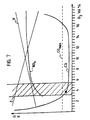
- FIG. 7 shows a diagram for assessing the quality of the combustion, the flue gases G and the system efficiency E being plotted as a function of the O 2 content in the flue gas G.
- the CO value is regarded as a superordinate measure of the quality of combustion.
- CO max the CO limit value
- the aim of the combustion control must therefore be to keep the O 2 value so low that the NO x content becomes minimal and at the same time the CO limit value is just maintained.
- Such an ideal working point is shown in the diagram.
- it also guarantees high system efficiency. Because of the optimized oxygen input with the present method, less air has to be blown through the firing material. This brings you closer to the basic goal of stoichiometric combustion. You also have less dust ejection. The dust particles are also less fast. This reduces the erosion of the boiler walls. Fast and many dust particles treat the boiler walls like sandblasting.
Landscapes
- Engineering & Computer Science (AREA)
- Mechanical Engineering (AREA)
- General Engineering & Computer Science (AREA)
- Chemical & Material Sciences (AREA)
- Combustion & Propulsion (AREA)
- Incineration Of Waste (AREA)
- Processing Of Solid Wastes (AREA)
- Solid-Fuel Combustion (AREA)
- Gasification And Melting Of Waste (AREA)
- Furnace Details (AREA)
Claims (9)
- Procédé pour la combustion de matières solides sur une grille de combustion à poussée, refroidie par eau, caractérisé en ce que l'air primaire amené, à travers la grille refroidie par eau, dans le lit de combustion arrive, après avoir traversé les plaques de la grille, sur des éléments de guidage (10, 12, 13, 14, 16), disposés au-dessus des embouchures placées dans la face frontale des plaques de grille et que l'air est dévié par chacun de ces éléments, de sorte que cet air primaire dévié s'écoule dans la matière en combustion de manière diffuse et à vitesse réduite, par comparaison avec sa vitesse dans la direction du courant d'air primaire sortant de la surface de la grille de poussée.
- Procédé suivant la revendication 1, caractérisé en ce que le courant d'air primaire s'écoule par des tubes (16), soudés dans la plaque (1 à 4) de grille et qui dépassent la surface de la plaque de grille et sont fermés dans le haut en forme de chapeaux, cependant qu'ils présentent des fentes latérales (19), s'étendant de biais vers le haut, vers le bas ou horizontalement, de sorte que l'air primaire sortant par ces fentes (19) s'écoule de manière diffuse dans la matière en combustion et contribue dans celle-ci à créer une pénétration homogène de l'air, avec une vitesse de pénétration lente de celui-ci.
- Procédé suivant une des revendications 1 à 2, caractérisé en ce que le courant d'air primaire, après être sorti de la surface de la grille à poussée, arrive sur des tôles de guidage (10) en forme d'étriers, disposées au-dessus d'embouchures en forme de trous longs s'étendant dans le sens de la poussée et formant un arc au-dessus de ces embouchures, cependant que le courant d'air primaire sortant de chaque embouchure est divisé et dévié sur la tôle de guidage (10) qui s'y trouve, de sorte que l'air primaire s'écoule de manière diffuse dans la matière en combustion et contribue dans celle-ci à créer une pénétration homogène de l'air, avec une vitesse de pénétration lente de celui-ci.
- Plaque de grille pour une grille de combustion à poussée, refroidie par eau et destinée à la combustion de matières solides, constituée par un corps creux (1 à 4), qui peut être traversé par des courants et comporte des tubulures de raccordement pour l'alimentation en eau de refroidissement et son évacuation ainsi que des canaux (9) d'alimentation en air primaire traversant de bas en haut la plaque de grille, caractérisée en ce qu'au-dessus des embouchures de ces canaux (9) d'alimentation en air primaire placées sur la face frontale de plaque il est disposé sur la surface de la plaque de grille des éléments de guidage (10, 12, 13, 14, 16), sur lesquels l'air primaire sortant des embouchures est destiné à arriver.
- Plaque de grille suivant la revendication 4, caractérisée en ce que les éléments de guidage (16) sont constitués de telle sorte que des tubes (16) à section transversale en forme de trous longs (17), qui sont fermés à une extrémité et forment à cet endroit un chapeau arrondi (18), sont, à leur extrémité ouverte, dirigés vers le bas, insérés dans des trous longs correspondants (17) pratiqués dans les tôles supérieure et inférieure de la plaque de grille et soudés jointivement dans ces trous longs, cependant que ces tubes dépassent, par leur extrémité (18) disposée du côté du chapeau, la surface de la plaque de grille et que, des deux côtés du tronçon dépassant la plaque de grille, ils présentent, au-dessous des chapeaux (18), dans les zones planes, des fentes (19), qui mènent, dans le tube (16), de l'intérieur vers l'extérieur et sont dirigées vers le bas, vers le haut ou horizontalement.
- Plaque de grille suivant la revendication 4, caractérisée en ce qu'au-dessus des embouchures des canaux (9) d'alimentation en air primaire sont soudés, sur l'avant de la plaque, des éléments de guidage constitués par des tôles de guidage (10) en forme d'étriers ou des fers plats (12) dépassant suivant un angle oblique les embouchures et sur lesquels l'air primaire sortant des embouchures est destiné à arriver.
- Plaque de grille suivant la revendication 4, caractérisée en ce que le long de l'arête avant de la plaque de grille il est soudé sur la plaque une tôle d'acier (13) en dents de scie, dont chaque dent dépasse une embouchure des canaux d'alimentation en air primaire et sur laquelle l'air primaire sortant des embouchures est destiné à arriver.
- Plaque de grille suivant la revendication 4, caractérisée en ce qu'au-dessus des embouchures circulaires des canaux (9) d'alimentation en air primaire sont disposés des éléments de guidages en forme de chapeaux (14) d'embouchures ou de buses, qui présentent des trous radiaux (15) pour la diffusion de l'air primaire qui arrive.
- Grille de combustion à poussée et en escalier, refroidie par eau, pour la combustion de matières solides, constituée de plaques de grille (1 à 4) reposant les unes sur les autres, suivant une des revendications 4 à 8, caractérisée en ce que chaque gradin de grille est composé d'une ou plusieurs de ces plaques de grille (1 à 4).
Applications Claiming Priority (6)
| Application Number | Priority Date | Filing Date | Title |
|---|---|---|---|
| CH249897 | 1997-10-29 | ||
| CH2498/97 | 1997-10-29 | ||
| CH249897 | 1997-10-29 | ||
| CH990/98 | 1998-05-03 | ||
| CH99098 | 1998-05-03 | ||
| CH99098 | 1998-05-03 |
Publications (3)
| Publication Number | Publication Date |
|---|---|
| EP0919771A2 EP0919771A2 (fr) | 1999-06-02 |
| EP0919771A3 EP0919771A3 (fr) | 1999-07-07 |
| EP0919771B1 true EP0919771B1 (fr) | 2000-11-29 |
Family
ID=25686326
Family Applications (1)
| Application Number | Title | Priority Date | Filing Date |
|---|---|---|---|
| EP98810971A Expired - Lifetime EP0919771B1 (fr) | 1997-10-29 | 1998-09-28 | Procédé de combustion pour matières solides sur une grille coulissante refroidie par eau, ainsi que barreau de grille et grille pour la mise en oeuvre du procédé |
Country Status (8)
| Country | Link |
|---|---|
| US (1) | US6155184A (fr) |
| EP (1) | EP0919771B1 (fr) |
| JP (1) | JP3037666B2 (fr) |
| KR (1) | KR19990037436A (fr) |
| AT (1) | ATE197845T1 (fr) |
| CA (1) | CA2249842A1 (fr) |
| DE (1) | DE59800363D1 (fr) |
| NO (1) | NO984541L (fr) |
Families Citing this family (9)
| Publication number | Priority date | Publication date | Assignee | Title |
|---|---|---|---|---|
| US6981455B2 (en) * | 2002-03-08 | 2006-01-03 | Lefcort Malcolm D | Two-stage wet waste gasifier and burner |
| DE102004040048A1 (de) * | 2004-08-18 | 2006-02-23 | Ikn Gmbh | Rostplattenanordnung für Stufenroste |
| CN101046293B (zh) * | 2006-03-28 | 2011-11-09 | 高桥贤三 | 加煤机型热分解炉 |
| DE102009009285B4 (de) * | 2009-02-17 | 2013-11-28 | Ikn Gmbh | Rostplattenanordnung |
| ES2686553T3 (es) * | 2014-09-16 | 2018-10-18 | Hitachi Zosen Inova Ag | Procedimiento y dispositivo para el tratamiento de escorias que se producen en una cámara de combustión de una planta de incineración de basuras |
| CN104197318B (zh) * | 2014-09-19 | 2017-03-22 | 四川能节环保科技有限公司 | 洁净煤绿色低氮燃烧高效节能减碳炉 |
| CN107850302B (zh) * | 2015-06-12 | 2020-09-04 | 日立造船爱诺瓦公司 | 用于燃烧炉排的炉排块、燃烧炉排及其用途和废物燃烧设施 |
| NO343011B1 (en) * | 2017-04-26 | 2018-09-24 | Aitos Gasification Tech As | Furnace for gasification and oxidation of solid fuel |
| CN114450520B (zh) * | 2019-07-05 | 2026-03-24 | 科纳维爱诺瓦公司 | 用于焚烧炉排的炉排块 |
Family Cites Families (22)
| Publication number | Priority date | Publication date | Assignee | Title |
|---|---|---|---|---|
| US1140158A (en) * | 1914-07-21 | 1915-05-18 | Charles William Hopes | Grate-bar. |
| US1542910A (en) * | 1921-11-25 | 1925-06-23 | Core H Reid | Fuel-burning grate |
| US1607258A (en) * | 1923-07-05 | 1926-11-16 | John G Gibson | Water grate |
| US1482501A (en) * | 1923-07-11 | 1924-02-05 | Nicholas J Zuzulin | Attachment for grates |
| US1779852A (en) * | 1927-05-16 | 1930-10-28 | Iron Fireman Mfg Co | Coal-burning grate |
| US1823235A (en) * | 1928-11-05 | 1931-09-15 | Ernest E Lee Co | Furnace grate bar |
| US2057276A (en) * | 1930-11-05 | 1936-10-13 | Guy J Morgan | Apparatus for burning fuel |
| US2033570A (en) * | 1931-10-26 | 1936-03-10 | Virginius M Cruikshank | Grate |
| CH636942A5 (de) * | 1979-05-30 | 1983-06-30 | Sulzer Ag | Wirbelschichtfeuerung mit einem ebenen rost. |
| JPS56149518A (en) * | 1980-04-21 | 1981-11-19 | Satake Eng Co Ltd | Granular material combustor |
| JPS5824720A (ja) * | 1982-07-12 | 1983-02-14 | Takuma Co Ltd | 階段式中空スト−カ |
| JPS6033419A (ja) * | 1983-08-03 | 1985-02-20 | Ishikawajima Harima Heavy Ind Co Ltd | 焼却残渣処理装置 |
| JPS60101533U (ja) * | 1983-12-15 | 1985-07-11 | 有限会社 極厚鋼管 | 炉床 |
| FR2574160A1 (fr) * | 1984-11-30 | 1986-06-06 | Electricite De France | Grille de foyer realisee a partir d'elements permettant un controle ameliore de l'apport en air primaire |
| DE3521266A1 (de) * | 1985-06-13 | 1986-12-18 | Walter Josef Dipl.-Ing. 8000 München Martin | Roststab fuer einen feuerungsrost einer grossfeuerung und feuerungsrost fuer diese grossfeuerung |
| JPH0769048B2 (ja) * | 1991-05-21 | 1995-07-26 | 日本鋼管株式会社 | ごみ焼却炉用火格子 |
| CH684118A5 (de) | 1993-04-20 | 1994-07-15 | Doikos Investments Ltd | Verfahren zum Verbrennen von Kehricht auf einem Verbrennungsrost sowie Verbrennungsrost zur Ausübung des Verfahrens und Rostplatte für einen solchen Verbrennungsrost. |
| DE4400992C1 (de) * | 1994-01-14 | 1995-05-11 | Noell Abfall & Energietech | Roststab und Rost mit Kühleinrichtung |
| DE19528310A1 (de) * | 1995-08-02 | 1997-02-06 | Abb Management Ag | Rost für eine Feuerungsanlage |
| US5575642A (en) * | 1995-12-01 | 1996-11-19 | The Carondelet Corporation | Grate plate |
| DE19633969A1 (de) * | 1996-08-22 | 1998-02-26 | Karl Von Wedel | Schüttgutrost |
| NO312644B1 (no) * | 1997-04-23 | 2002-06-10 | Doikos Investments Ltd | Vannkjölt trykkforbrenningsrist |
-
1998
- 1998-09-28 EP EP98810971A patent/EP0919771B1/fr not_active Expired - Lifetime
- 1998-09-28 AT AT98810971T patent/ATE197845T1/de not_active IP Right Cessation
- 1998-09-28 DE DE59800363T patent/DE59800363D1/de not_active Expired - Fee Related
- 1998-09-29 NO NO984541A patent/NO984541L/no not_active Application Discontinuation
- 1998-10-08 CA CA002249842A patent/CA2249842A1/fr not_active Abandoned
- 1998-10-27 US US09/179,275 patent/US6155184A/en not_active Expired - Fee Related
- 1998-10-28 KR KR1019980045233A patent/KR19990037436A/ko not_active Ceased
- 1998-10-29 JP JP10309152A patent/JP3037666B2/ja not_active Expired - Fee Related
Also Published As
| Publication number | Publication date |
|---|---|
| JPH11211045A (ja) | 1999-08-06 |
| EP0919771A3 (fr) | 1999-07-07 |
| CA2249842A1 (fr) | 1999-04-29 |
| ATE197845T1 (de) | 2000-12-15 |
| KR19990037436A (ko) | 1999-05-25 |
| DE59800363D1 (de) | 2001-01-04 |
| JP3037666B2 (ja) | 2000-04-24 |
| NO984541D0 (no) | 1998-09-29 |
| US6155184A (en) | 2000-12-05 |
| NO984541L (no) | 1999-04-30 |
| EP0919771A2 (fr) | 1999-06-02 |
Similar Documents
| Publication | Publication Date | Title |
|---|---|---|
| DE3313615C2 (de) | Rostblock eines Rostbelages zu einem Verbrennungsrost zur Müllverbrennung | |
| EP0621449B1 (fr) | Procédé pour la combustion de déchets sur une grille de combustion ainsi qu'une grille de combustion pour la mise en oeuvre du procédé et barreau pour la fabrication d'une telle grille | |
| EP0954722B1 (fr) | Grille de combustion a refroidissement par eau | |
| EP0919771B1 (fr) | Procédé de combustion pour matières solides sur une grille coulissante refroidie par eau, ainsi que barreau de grille et grille pour la mise en oeuvre du procédé | |
| EP0499912A2 (fr) | Barreau de grille et grille pour installations de combustion | |
| EP0157920B2 (fr) | Rouleau de grille pour grille à rouleaux par exemple d'une installation d'incinération des ordures ou similaire | |
| EP0165432A1 (fr) | Four, notamment pour la combustion des ordures, du charbon, du bois et des déchets industriels | |
| CH615745A5 (fr) | ||
| EP2184540B1 (fr) | Bloc de grille à refroidissement par air | |
| DE3226877A1 (de) | Heizkessel | |
| EP1001218B1 (fr) | Grille de combustion refroidie par eau et procédé de combustion de déchets correspondant | |
| DE3813441C2 (fr) | ||
| EP0288597B1 (fr) | Feu à grille pour l'incinération des déchets | |
| DE29605801U1 (de) | Heizkessel | |
| EP0391146B1 (fr) | Installation de combustion pour brûler un matériau de combustion, en particulier des ordures | |
| EP0733855B1 (fr) | Grille à rouleaux | |
| DE4435749C2 (de) | Heizvorrichtung für feste Brennstoffe | |
| DE3712039A1 (de) | Verbrennungskessel, insbesondere zur muellverbrennung | |
| CH645964A5 (de) | Feuerungsanlage fuer feste brennstoffe. | |
| EP0733854B1 (fr) | Procédé et grille à rouleaux pour l'incinération de déchets | |
| AT407915B (de) | Luftleitvorrichtung für die zuluft von heizeinrichtungen | |
| DE19502261A1 (de) | Verfahren und Verbrennungsrost zum Verbrennen von festen Brennstoffen wie Müll, insbesondere zur Verbesserung des Ausbrandes | |
| DE968422C (de) | Gasbrenner zum Oberflaechenhaerten, insbesondere Brennhaerten von Werkstuecken | |
| DE3037075C2 (de) | Brennstoff-Fördereinrichtung für eine Rostfeuerung | |
| DE75305C (de) | Verfahren zur Behandlung von Feuerungsroaterial auf dem Roste |
Legal Events
| Date | Code | Title | Description |
|---|---|---|---|
| PUAI | Public reference made under article 153(3) epc to a published international application that has entered the european phase |
Free format text: ORIGINAL CODE: 0009012 |
|
| PUAL | Search report despatched |
Free format text: ORIGINAL CODE: 0009013 |
|
| AK | Designated contracting states |
Kind code of ref document: A2 Designated state(s): AT BE CH DE DK ES FR GB IE IT LI NL SE |
|
| AX | Request for extension of the european patent |
Free format text: AL;LT;LV;MK;RO;SI |
|
| AK | Designated contracting states |
Kind code of ref document: A3 Designated state(s): AT BE CH CY DE DK ES FI FR GB GR IE IT LI LU MC NL PT SE |
|
| AX | Request for extension of the european patent |
Free format text: AL;LT;LV;MK;RO;SI |
|
| 17P | Request for examination filed |
Effective date: 19990728 |
|
| 17Q | First examination report despatched |
Effective date: 19990923 |
|
| GRAG | Despatch of communication of intention to grant |
Free format text: ORIGINAL CODE: EPIDOS AGRA |
|
| 17Q | First examination report despatched |
Effective date: 19990923 |
|
| AKX | Designation fees paid |
Free format text: AT BE CH DE DK ES FR GB IE IT LI NL SE |
|
| GRAG | Despatch of communication of intention to grant |
Free format text: ORIGINAL CODE: EPIDOS AGRA |
|
| GRAH | Despatch of communication of intention to grant a patent |
Free format text: ORIGINAL CODE: EPIDOS IGRA |
|
| GRAH | Despatch of communication of intention to grant a patent |
Free format text: ORIGINAL CODE: EPIDOS IGRA |
|
| GRAA | (expected) grant |
Free format text: ORIGINAL CODE: 0009210 |
|
| AK | Designated contracting states |
Kind code of ref document: B1 Designated state(s): AT BE CH DE DK ES FR GB IE IT LI NL SE |
|
| PG25 | Lapsed in a contracting state [announced via postgrant information from national office to epo] |
Ref country code: NL Free format text: LAPSE BECAUSE OF FAILURE TO SUBMIT A TRANSLATION OF THE DESCRIPTION OR TO PAY THE FEE WITHIN THE PRESCRIBED TIME-LIMIT Effective date: 20001129 Ref country code: IT Free format text: LAPSE BECAUSE OF FAILURE TO SUBMIT A TRANSLATION OF THE DESCRIPTION OR TO PAY THE FEE WITHIN THE PRESCRIBED TIME-LIMIT;WARNING: LAPSES OF ITALIAN PATENTS WITH EFFECTIVE DATE BEFORE 2007 MAY HAVE OCCURRED AT ANY TIME BEFORE 2007. THE CORRECT EFFECTIVE DATE MAY BE DIFFERENT FROM THE ONE RECORDED. Effective date: 20001129 Ref country code: IE Free format text: LAPSE BECAUSE OF NON-PAYMENT OF DUE FEES Effective date: 20001129 Ref country code: GB Free format text: LAPSE BECAUSE OF FAILURE TO SUBMIT A TRANSLATION OF THE DESCRIPTION OR TO PAY THE FEE WITHIN THE PRESCRIBED TIME-LIMIT Effective date: 20001129 Ref country code: ES Free format text: THE PATENT HAS BEEN ANNULLED BY A DECISION OF A NATIONAL AUTHORITY Effective date: 20001129 |
|
| REF | Corresponds to: |
Ref document number: 197845 Country of ref document: AT Date of ref document: 20001215 Kind code of ref document: T |
|
| REG | Reference to a national code |
Ref country code: CH Ref legal event code: EP |
|
| REF | Corresponds to: |
Ref document number: 59800363 Country of ref document: DE Date of ref document: 20010104 |
|
| REG | Reference to a national code |
Ref country code: CH Ref legal event code: NV Representative=s name: FELBER & PARTNER AG PATENTANWAELTE |
|
| ET | Fr: translation filed | ||
| REG | Reference to a national code |
Ref country code: IE Ref legal event code: FG4D Free format text: GERMAN |
|
| PG25 | Lapsed in a contracting state [announced via postgrant information from national office to epo] |
Ref country code: SE Free format text: LAPSE BECAUSE OF FAILURE TO SUBMIT A TRANSLATION OF THE DESCRIPTION OR TO PAY THE FEE WITHIN THE PRESCRIBED TIME-LIMIT Effective date: 20010228 Ref country code: DK Free format text: LAPSE BECAUSE OF FAILURE TO SUBMIT A TRANSLATION OF THE DESCRIPTION OR TO PAY THE FEE WITHIN THE PRESCRIBED TIME-LIMIT Effective date: 20010228 |
|
| NLV1 | Nl: lapsed or annulled due to failure to fulfill the requirements of art. 29p and 29m of the patents act | ||
| GBV | Gb: ep patent (uk) treated as always having been void in accordance with gb section 77(7)/1977 [no translation filed] |
Effective date: 20001129 |
|
| REG | Reference to a national code |
Ref country code: IE Ref legal event code: FD4D |
|
| PG25 | Lapsed in a contracting state [announced via postgrant information from national office to epo] |
Ref country code: AT Free format text: LAPSE BECAUSE OF NON-PAYMENT OF DUE FEES Effective date: 20010928 |
|
| PG25 | Lapsed in a contracting state [announced via postgrant information from national office to epo] |
Ref country code: BE Free format text: LAPSE BECAUSE OF NON-PAYMENT OF DUE FEES Effective date: 20010930 |
|
| PLBE | No opposition filed within time limit |
Free format text: ORIGINAL CODE: 0009261 |
|
| STAA | Information on the status of an ep patent application or granted ep patent |
Free format text: STATUS: NO OPPOSITION FILED WITHIN TIME LIMIT |
|
| 26N | No opposition filed | ||
| BERE | Be: lapsed |
Owner name: DOIKOS INVESTMENTS LTD Effective date: 20010930 |
|
| PGFP | Annual fee paid to national office [announced via postgrant information from national office to epo] |
Ref country code: CH Payment date: 20020919 Year of fee payment: 5 |
|
| PGFP | Annual fee paid to national office [announced via postgrant information from national office to epo] |
Ref country code: FR Payment date: 20020930 Year of fee payment: 5 |
|
| PGFP | Annual fee paid to national office [announced via postgrant information from national office to epo] |
Ref country code: DE Payment date: 20021216 Year of fee payment: 5 |
|
| PG25 | Lapsed in a contracting state [announced via postgrant information from national office to epo] |
Ref country code: LI Free format text: LAPSE BECAUSE OF NON-PAYMENT OF DUE FEES Effective date: 20030930 Ref country code: CH Free format text: LAPSE BECAUSE OF NON-PAYMENT OF DUE FEES Effective date: 20030930 |
|
| PG25 | Lapsed in a contracting state [announced via postgrant information from national office to epo] |
Ref country code: DE Free format text: LAPSE BECAUSE OF NON-PAYMENT OF DUE FEES Effective date: 20040401 |
|
| REG | Reference to a national code |
Ref country code: CH Ref legal event code: PL |
|
| PG25 | Lapsed in a contracting state [announced via postgrant information from national office to epo] |
Ref country code: FR Free format text: LAPSE BECAUSE OF NON-PAYMENT OF DUE FEES Effective date: 20040528 |
|
| REG | Reference to a national code |
Ref country code: FR Ref legal event code: ST |