EP0919771B1 - Combustion process for solid material on a water-cooled sliding grate as well as gratebar and grate for carrying out the process - Google Patents
Combustion process for solid material on a water-cooled sliding grate as well as gratebar and grate for carrying out the process Download PDFInfo
- Publication number
- EP0919771B1 EP0919771B1 EP98810971A EP98810971A EP0919771B1 EP 0919771 B1 EP0919771 B1 EP 0919771B1 EP 98810971 A EP98810971 A EP 98810971A EP 98810971 A EP98810971 A EP 98810971A EP 0919771 B1 EP0919771 B1 EP 0919771B1
- Authority
- EP
- European Patent Office
- Prior art keywords
- grate
- primary air
- plates
- combustion
- openings
- Prior art date
- Legal status (The legal status is an assumption and is not a legal conclusion. Google has not performed a legal analysis and makes no representation as to the accuracy of the status listed.)
- Expired - Lifetime
Links
- 238000002485 combustion reaction Methods 0.000 title claims abstract description 62
- 238000000034 method Methods 0.000 title claims description 13
- 239000011343 solid material Substances 0.000 title 1
- 239000000463 material Substances 0.000 claims description 21
- 239000007787 solid Substances 0.000 claims description 9
- 229910000831 Steel Inorganic materials 0.000 claims description 4
- 239000010959 steel Substances 0.000 claims description 4
- 239000000498 cooling water Substances 0.000 claims description 2
- 238000009841 combustion method Methods 0.000 abstract 1
- 239000004449 solid propellant Substances 0.000 abstract 1
- 238000010304 firing Methods 0.000 description 19
- 239000003546 flue gas Substances 0.000 description 11
- UGFAIRIUMAVXCW-UHFFFAOYSA-N Carbon monoxide Chemical compound [O+]#[C-] UGFAIRIUMAVXCW-UHFFFAOYSA-N 0.000 description 9
- XEEYBQQBJWHFJM-UHFFFAOYSA-N Iron Chemical compound [Fe] XEEYBQQBJWHFJM-UHFFFAOYSA-N 0.000 description 8
- 239000000428 dust Substances 0.000 description 5
- JEIPFZHSYJVQDO-UHFFFAOYSA-N iron(III) oxide Inorganic materials O=[Fe]O[Fe]=O JEIPFZHSYJVQDO-UHFFFAOYSA-N 0.000 description 5
- 239000002893 slag Substances 0.000 description 5
- QVGXLLKOCUKJST-UHFFFAOYSA-N atomic oxygen Chemical compound [O] QVGXLLKOCUKJST-UHFFFAOYSA-N 0.000 description 4
- 238000001816 cooling Methods 0.000 description 4
- 238000010586 diagram Methods 0.000 description 4
- 229910052742 iron Inorganic materials 0.000 description 4
- 239000001301 oxygen Substances 0.000 description 4
- 229910052760 oxygen Inorganic materials 0.000 description 4
- 239000007789 gas Substances 0.000 description 3
- 239000002184 metal Substances 0.000 description 3
- 229910052751 metal Inorganic materials 0.000 description 3
- 239000010813 municipal solid waste Substances 0.000 description 3
- 238000004056 waste incineration Methods 0.000 description 3
- XLYOFNOQVPJJNP-UHFFFAOYSA-N water Substances O XLYOFNOQVPJJNP-UHFFFAOYSA-N 0.000 description 3
- 239000002956 ash Substances 0.000 description 2
- POIUWJQBRNEFGX-XAMSXPGMSA-N cathelicidin Chemical compound C([C@@H](C(=O)N[C@@H](CCCNC(N)=N)C(=O)N[C@@H](CCCCN)C(=O)N[C@@H](CO)C(=O)N[C@@H](CCCCN)C(=O)N[C@@H](CCC(O)=O)C(=O)N[C@@H](CCCCN)C(=O)N[C@@H]([C@@H](C)CC)C(=O)NCC(=O)N[C@@H](CCCCN)C(=O)N[C@@H](CCC(O)=O)C(=O)N[C@@H](CC=1C=CC=CC=1)C(=O)N[C@@H](CCCCN)C(=O)N[C@@H](CCCNC(N)=N)C(=O)N[C@@H]([C@@H](C)CC)C(=O)N[C@@H](C(C)C)C(=O)N[C@@H](CCC(N)=O)C(=O)N[C@@H](CCCNC(N)=N)C(=O)N[C@@H]([C@@H](C)CC)C(=O)N[C@@H](CCCCN)C(=O)N[C@@H](CC(O)=O)C(=O)N[C@@H](CC=1C=CC=CC=1)C(=O)N[C@@H](CC(C)C)C(=O)N[C@@H](CCCNC(N)=N)C(=O)N[C@@H](CC(N)=O)C(=O)N[C@@H](CC(C)C)C(=O)N[C@@H](C(C)C)C(=O)N1[C@@H](CCC1)C(=O)N[C@@H](CCCNC(N)=N)C(=O)N[C@@H]([C@@H](C)O)C(=O)N[C@@H](CCC(O)=O)C(=O)N[C@@H](CO)C(O)=O)NC(=O)[C@H](CC=1C=CC=CC=1)NC(=O)[C@H](CC(O)=O)NC(=O)CNC(=O)[C@H](CC(C)C)NC(=O)[C@@H](N)CC(C)C)C1=CC=CC=C1 POIUWJQBRNEFGX-XAMSXPGMSA-N 0.000 description 2
- 230000003247 decreasing effect Effects 0.000 description 2
- 238000009792 diffusion process Methods 0.000 description 2
- 239000010791 domestic waste Substances 0.000 description 2
- 239000010881 fly ash Substances 0.000 description 2
- 239000002245 particle Substances 0.000 description 2
- 230000035515 penetration Effects 0.000 description 2
- -1 sawdust Substances 0.000 description 2
- 206010010774 Constipation Diseases 0.000 description 1
- 206010012735 Diarrhoea Diseases 0.000 description 1
- 230000009286 beneficial effect Effects 0.000 description 1
- 230000015572 biosynthetic process Effects 0.000 description 1
- 239000003795 chemical substances by application Substances 0.000 description 1
- 239000000567 combustion gas Substances 0.000 description 1
- 238000010276 construction Methods 0.000 description 1
- 238000011109 contamination Methods 0.000 description 1
- 239000002826 coolant Substances 0.000 description 1
- 230000007423 decrease Effects 0.000 description 1
- 230000001627 detrimental effect Effects 0.000 description 1
- 238000006073 displacement reaction Methods 0.000 description 1
- 230000000694 effects Effects 0.000 description 1
- 230000002996 emotional effect Effects 0.000 description 1
- 230000003628 erosive effect Effects 0.000 description 1
- 239000002440 industrial waste Substances 0.000 description 1
- 238000009434 installation Methods 0.000 description 1
- 230000001788 irregular Effects 0.000 description 1
- 239000003077 lignite Substances 0.000 description 1
- 239000002906 medical waste Substances 0.000 description 1
- 239000000203 mixture Substances 0.000 description 1
- 238000013021 overheating Methods 0.000 description 1
- 238000006213 oxygenation reaction Methods 0.000 description 1
- 230000000149 penetrating effect Effects 0.000 description 1
- 230000035699 permeability Effects 0.000 description 1
- 230000000704 physical effect Effects 0.000 description 1
- 238000005488 sandblasting Methods 0.000 description 1
- 239000010801 sewage sludge Substances 0.000 description 1
- 239000002023 wood Substances 0.000 description 1
Images

Classifications
-
- F—MECHANICAL ENGINEERING; LIGHTING; HEATING; WEAPONS; BLASTING
- F23—COMBUSTION APPARATUS; COMBUSTION PROCESSES
- F23G—CREMATION FURNACES; CONSUMING WASTE PRODUCTS BY COMBUSTION
- F23G5/00—Incineration of waste; Incinerator constructions; Details, accessories or control therefor
- F23G5/002—Incineration of waste; Incinerator constructions; Details, accessories or control therefor characterised by their grates
-
- F—MECHANICAL ENGINEERING; LIGHTING; HEATING; WEAPONS; BLASTING
- F23—COMBUSTION APPARATUS; COMBUSTION PROCESSES
- F23H—GRATES; CLEANING OR RAKING GRATES
- F23H7/00—Inclined or stepped grates
- F23H7/06—Inclined or stepped grates with movable bars disposed parallel to direction of fuel feeding
- F23H7/08—Inclined or stepped grates with movable bars disposed parallel to direction of fuel feeding reciprocating along their axes
-
- F—MECHANICAL ENGINEERING; LIGHTING; HEATING; WEAPONS; BLASTING
- F23—COMBUSTION APPARATUS; COMBUSTION PROCESSES
- F23H—GRATES; CLEANING OR RAKING GRATES
- F23H1/00—Grates with solid bars
- F23H1/02—Grates with solid bars having provision for air supply or air preheating, e.g. air-supply or blast fittings which form a part of the grate structure or serve as supports
-
- F—MECHANICAL ENGINEERING; LIGHTING; HEATING; WEAPONS; BLASTING
- F23—COMBUSTION APPARATUS; COMBUSTION PROCESSES
- F23H—GRATES; CLEANING OR RAKING GRATES
- F23H11/00—Travelling-grates
- F23H11/12—Travelling-grates inclined travelling grates; Stepped travelling grates
-
- F—MECHANICAL ENGINEERING; LIGHTING; HEATING; WEAPONS; BLASTING
- F23—COMBUSTION APPARATUS; COMBUSTION PROCESSES
- F23H—GRATES; CLEANING OR RAKING GRATES
- F23H3/00—Grates with hollow bars
- F23H3/02—Grates with hollow bars internally cooled
-
- F—MECHANICAL ENGINEERING; LIGHTING; HEATING; WEAPONS; BLASTING
- F23—COMBUSTION APPARATUS; COMBUSTION PROCESSES
- F23L—SUPPLYING AIR OR NON-COMBUSTIBLE LIQUIDS OR GASES TO COMBUSTION APPARATUS IN GENERAL ; VALVES OR DAMPERS SPECIALLY ADAPTED FOR CONTROLLING AIR SUPPLY OR DRAUGHT IN COMBUSTION APPARATUS; INDUCING DRAUGHT IN COMBUSTION APPARATUS; TOPS FOR CHIMNEYS OR VENTILATING SHAFTS; TERMINALS FOR FLUES
- F23L1/00—Passages or apertures for delivering primary air for combustion
- F23L1/02—Passages or apertures for delivering primary air for combustion by discharging the air below the fire
-
- F—MECHANICAL ENGINEERING; LIGHTING; HEATING; WEAPONS; BLASTING
- F23—COMBUSTION APPARATUS; COMBUSTION PROCESSES
- F23H—GRATES; CLEANING OR RAKING GRATES
- F23H2700/00—Grates characterised by special features or applications
- F23H2700/009—Grates specially adapted for incinerators
-
- F—MECHANICAL ENGINEERING; LIGHTING; HEATING; WEAPONS; BLASTING
- F23—COMBUSTION APPARATUS; COMBUSTION PROCESSES
- F23H—GRATES; CLEANING OR RAKING GRATES
- F23H2900/00—Special features of combustion grates
- F23H2900/03021—Liquid cooled grates
Definitions
- the invention relates to a method for burning solids on a water-cooled Thrust combustion grate, such as that used in waste incineration plants Installation is coming. Furthermore, it is about a specific grate plate and one made of such Rust plates built up rust, as is necessary to carry out the process.
- the too burning solids can be a wide variety of types of solids, be it lignite, sawdust, wood and rubber chips, all sorts of residual goods, Industrial waste, sewage sludge, hospital or household waste or rubbish, etc. etc.
- the primary air is blown through from below the grate through the grate into the combustion bed.
- the primary air reaches the top of the grate through recesses in the cast grate bars on the side and / or in the head region. The primary air is conveyed through the grate by building up corresponding overpressures of the order of magnitude of approx.
- the grate plates then have primary air supply channels on, for example, primary air supply pipes passing through the grate plate, which can also taper towards the top, or are the primary air supply channels formed by recesses for the passage of primary air, so that the primary air that is, it can be conducted from below the grate through it onto its upper side.
- the grate plates that run across the width can no longer slag between individual Grate elements fall under the grate, as is the case with grate levels consisting of several loose parts adjacent grate bars is the case. This makes slag diarrhea practical prevented.
- a grate has become known, in which the grate bars each consist of two nested profiles are shaped so that the air flowing through the rods passes through the attached ones Longitudinal profiles flow horizontally and laterally.
- the air diverted in this way is not pure primary air, but primarily cooling air, and the grate is not water-cooled Thrust combustion grate.
- EP 0'019'652 A (SULZER AG), December 10, 1980 shows a grate for a fluidized bed firing, which consists of water flowing through, parallel to each other at a distance arranged pipes, which are welded to each other with an intermediate web are.
- the primary air flows through the intermediate webs through air arranged therein Slits or holes upwards and flows around cover plates.
- these are not on a thrust combustion grate, and especially not on a water-cooled thrust combustion grate realized and can not be transferred directly to one.
- a method for burning solids a water-cooled thrust combustion grate which is characterized by the fact that the primary air fed into the combustion bed through the water-cooled thrust combustion grate after flowing through the grate plates of the thrust combustion grate on guide elements strikes, which over the mouths placed in the front of the grate plates are arranged, and is deflected by each such guide element, so that the deflected primary air - in comparison with its speed in the direction of the Sliding grate surface emerging primary air flow - at a slower speed flows diffusely into the firing material.
- a grate plate for consisting of a water-cooled thrust combustion grate for burning solids from a flow-through hollow body with connection piece for the supply and discharge of Cooling water, as well as primary air supply channels penetrating the grate plate from bottom to top, which is characterized by the fact that on the front of the grate plate placed the mouths of the primary air supply ducts on the grate plate surface are arranged, on which the primary air emerging from the mouth is intended to encounter.
- Thrust combustion grates have stationary and movable grate levels made of grate plates or from a series of grate bars, the grate steps being stepped on one another lie on. These sliding combustion grates can be installed so that the combustion bed in the is essentially horizontal, or inclined, with inclinations of up to 20 degrees or more are common.
- EP-0'621'449 describes a water-cooled thrust combustion grate known. Its grate plates are made of sheet steel and form board-shaped hollow bodies that extend across the width of the entire grating track and through which water is passed as a cooling medium. Every second grate plate is movable and can therefore perform a stoking or transport stroke.
- the movable grate plates can be fired with their end face Push it onto the next lower grate plate.
- a push-back grate forms a somewhat wrong built-in, inclined staircase.
- the end faces of the Movable grate plates transport the one behind them in a rear grate Firing material back, after which it rolls down again in the direction of the tendency to rust.
- the movable grate plates i.e. between two stationary grate plates arranged grate plates are usually collectively back and forth in the direction of their inclination emotional. This ensures that the burning rubbish lying on the grate at a long dwell time of 45 to 120 minutes constantly rearranged and even on the grate is distributed.
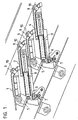
- FIG. 1 An advantageous construction of this thrust combustion grate with its essential elements can be seen in Figure 1, in which a portion of a thrust combustion grate is shown using a cross section.
- the grate consists of stairs Grate levels, which are each formed by a hollow, water-cooled grate plate 1,2,3,4. Every second grate level, in the figure the grate plates 2 and 4, is designed to be movable while the intermediate grate plates are suspended on cross tubes 5.
- the moveable Grate plates 2.4 are each laterally mounted on a roller 6 and lie with it Rear part on vertical rollers 7, which are arranged on the laterally delimiting planks are.
- Each movable grate plate 2.4 is from its own hydraulic piston-cylinder unit 8 driven.
- each grate plate open through the grate plate extending pipes 9 for the supply of primary air from the area below the Rust.
- These primary air supply pipes 9 open somewhat above the surface of the grate plate and have an elongated cross-section, as will be shown later becomes. In this way it has already been avoided that excessive amounts of these tubes Slag falls through.
- the mouths of these primary air pipes 9 or corresponding primary air supply channels are as shown here with guide elements 10 in the form of muzzle caps made of bow-shaped baffles that are simply welded onto the top of the grate plate are.
- the upper section of the baffles is V-shaped in cross section. The of The primary air jet hitting the bottom of these guide plates is therefore from the guide plates divided and distracted laterally.
- the bow-shaped baffles cover the mouth in the thrust direction of the grate, so that the fired material is guided around the baffles and does not directly cover the primary air outlets.
- FIG 2 is a part of the front edge of a grate plate with a design of the guide elements in the form of welded bow-shaped guide plates 10 in a perspective view shown.
- the mouth or nozzle caps 10 are welded in the form of the bow-shaped guide plates 10.
- These baffles 10 consist of sheet steel and form seen from the side, if they are welded on, a trapezoidal shape, the piece of sheet metal which the forms the upper side of the trapezoid, is V-shaped in cross section, which is indicated by a simple folding can be achieved.
- the one that hits from below becomes Primary air flow divided into two as indicated by the arrows and deflected laterally and thereby also swirled.
- the effect is that the air at a significantly reduced speed and penetrates diffusely into the kiln.
- the air passing through in a row arranged primary air orifices flows in, the combustion bed in its entirety Diffuse penetration wide, so that the atmospheric oxygen much more homogeneous than before Combustion is supplied.
- the bow-shaped Baffles can also form a semicircular arc, or one Angle welded onto the grate plate like a gable above the mouth.
- the Mounting direction can be chosen arbitrarily, so that the angular plane also in right angle to the direction of thrust. If the sheets as in the figure shown, this also ensures that the primary air supply openings are not clog.
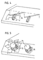
- Figure 3 shows a grate plate with a design of the guide elements in the form of welded flat baffles 12.
- This variant also fulfills the intended purpose, namely the deflection of the primary air and its diffusion, which in turn is indicated by arrows is.
- These flat bars 12 can serve a further purpose. They seem namely as barbs and take each time the movable plates are pushed forward the firing material lying in front of the area of the flat iron 12 while pulling it back release this again and then the primary air flows back to the flat iron 12 and it cools.
- FIG. 4 shows a further variant for a guide element, in this case a sawtooth-shaped one Sheet 13, similar to the shape of a cutter bar knife, across the width of the grate on the The front edge of the grate plate is welded on.
- the saw teeth each protrude above a nozzle the primary air supply, so that the emerging primary air flow onto one sawtooth each strikes and is deflected by this towards the front and the two sides.
- FIG. 5 shows an embodiment with screwed-on orifice caps 14.
- the primary air supply ducts or pipes are circular in this case and the pipe openings, which protrude slightly from the ros have an external thread.
- the nozzle cap 14 is screwed onto this.
- These nozzle caps 14 are standard fittings with hexagonal outer shape, which are used for this purpose be provided with radial bores 15.
- the fittings are only a small one Part of their thread screwed on, so that the primary air is unhindered by the radial Holes 15 can emerge. It is therefore after the pipe mouth of the fittings deflected and radially flows out through the six holes shown in the example, whereby it diffuses on all sides into the surrounding firing material, as indicated by the arrows. Clogging of the mouths arranged all around is due to the relative movement of the Mouth and nozzle caps 14 to the transported firing material impossible.
- Such nozzle caps can of course also have other shapes and are welded on instead of being screwed on.
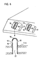
- FIG. 6 shows a further embodiment variant for the guide elements. These exist here from tubes 16 with an elongated cross section 17. These tubes 16 are at one end closed and there form a rounded cap 18. With its open side down these tubes 16 are directed into corresponding elongated holes in the upper and lower grate plate used and sealed in these elongated holes. They are there longer than the grate plate thickness and with its lower end flush with the underside welded into the grate plate so that it can then be Exceed the grate plate surface at the end. On both sides of the grate overhanging the grate Section of the tubes 16 are below, the caps 18 in the flat areas Slots 19 are provided, which are directed in the tube 16 from the inside outwards towards the bottom.
- the air is thereby deflected in the cap 18 and then flows depending on Execution of the slots 19 in the caps 18 upwards, horizontally or obliquely downwards through them onto the garbage bed, and secondly, the slots 19 are through this arrangement largely protected against constipation from fired goods, because they only move lengthways of the kiln and, as I said, are directed downwards.
- the rounded Caps 18 can the pipe sections that protrude beyond the grate plate surface with the move the moving grate plates through the firing material, or the firing material can touch it Pipe sections are pushed past without getting stuck on sharp edges and a pipe 16 may be deformed or even torn thereby.
- such guide elements described for the figures can be on the top the grate can only be realized on water-cooled grates, because these remain in operation at a low temperature so that most of the heat comes from the guide elements the rust is drained off. On the other hand, such elements would be innate on air-cooled grates burn in no time.
- a thrust combustion grate built up from water-cooled grate plates can also such guiding elements and then basically allows that through the shear combustion grate on the combustion bed supplied primary air after the outlet the sliding grate surface is first deflected.
- the resulting diffusion of the primary air and consequently its more homogeneous penetration of the combustion bed turns out to be enormously beneficial for the quality of the combustion.
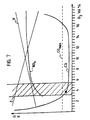
- FIG. 7 shows a diagram for assessing the quality of the combustion, the flue gases G and the system efficiency E being plotted as a function of the O 2 content in the flue gas G.
- the CO value is regarded as a superordinate measure of the quality of combustion.
- CO max the CO limit value
- the aim of the combustion control must therefore be to keep the O 2 value so low that the NO x content becomes minimal and at the same time the CO limit value is just maintained.
- Such an ideal working point is shown in the diagram.
- it also guarantees high system efficiency. Because of the optimized oxygen input with the present method, less air has to be blown through the firing material. This brings you closer to the basic goal of stoichiometric combustion. You also have less dust ejection. The dust particles are also less fast. This reduces the erosion of the boiler walls. Fast and many dust particles treat the boiler walls like sandblasting.
Landscapes
- Engineering & Computer Science (AREA)
- Mechanical Engineering (AREA)
- General Engineering & Computer Science (AREA)
- Chemical & Material Sciences (AREA)
- Combustion & Propulsion (AREA)
- Incineration Of Waste (AREA)
- Processing Of Solid Wastes (AREA)
- Solid-Fuel Combustion (AREA)
- Furnace Details (AREA)
- Gasification And Melting Of Waste (AREA)
Abstract
Description
Die Erfindung betrifft ein Verfahren zum Verbrennen von Feststoffen auf einem wassergekühlten Schub-Verbrennungsrost, wie er zum Beispiel in Kehrichtverbrennungsanlagen zum Einbau kommt. Desweiteren geht es um eine spezifische Rostplatte und einen aus solchen Rostplatten aufgebauten Rost, wie er zur Durchführung des Verfahrens nötig ist. Bei den zu verbrennenden Feststoffen kann es sich um verschiedenste Arten von Feststoffen handeln, sei es Braunkohle, Sägespäne, Holz- und Gummi-Schnitzel, allerlei Restwaren, Industrieabfall, Klärschlamm, Krankenhaus- oder Haushaltmüll bzw. Kehricht, usw. usf.The invention relates to a method for burning solids on a water-cooled Thrust combustion grate, such as that used in waste incineration plants Installation is coming. Furthermore, it is about a specific grate plate and one made of such Rust plates built up rust, as is necessary to carry out the process. With the too burning solids can be a wide variety of types of solids, be it lignite, sawdust, wood and rubber chips, all sorts of residual goods, Industrial waste, sewage sludge, hospital or household waste or rubbish, etc. etc.
Bei den herkömmlichen Schubverbrennungsrosten, welche in Kehrichtverbrennungsanlagen zum Einbau kommen, und die aus treppenförmig aufeinanderliegenden Roststufen bestehen, von denen jede zweite in Schubrichtung beweglich ist, wird die Primärluft von unterhalb des Rostes durch diesen hindurch in das Brennbett geblasen. Bei den noch mehrheitlich im Einsatz stehenden Gussrosten, bei denen also die einzelnen Roststufen aus einer Reihe lose nebeneinanderliegender oder miteinander verschraubter Guss-Roststäbe bestehen, gelangt die Primärluft durch seitliche und/oder im Kopfbereich angebrachte Ausnehmungen in den Gussroststäben auf die Rostoberseite. Die Primärluft wird durch den Rost hindurch gefördert, indem in den Zonen unterhalb des Rostes mittels grossdimensionierter Ventilatoren entsprechende Ueberdrucke der Grössenordnung von ca. 40mm bis 250mm Wassersäule aufgebaut werden. Pro Rostoberfläche sieht man etwa 2% als freibleibenden Durchgangsquerschnitt für die Primärluft vor, und pro Quadratmeter Rostoberfläche werden bis 2'500 m3 Luft pro Stunde durch den Rost gefördert, um eine Vorstellung von der Grössenordnung des Luftdurchsatzes zu vermitteln. Die Geschwindigkeit der durchströmenden Luft erreicht dabei Spitzen von über 30m/s. Diese durch den Rost strömende Luft dient zum einen als Primärluft für das Feuer, zum ändern als Kühlluft für den Gussrost. Ein Nachteil dieses Konzeptes ist, dass die Luft recht unausgeglichen in das Brennbett gelangt. Verklemmt sich zum Beispiel ein Draht oder ein sonstiges Kleinteil zwischen zwei benachbarten Roststäben, so ist der Abstand zwischen diesen auf Kosten der Abstände zwischen den übrigen Roststäben erweitert. Das hat zur Folge, dass durch diesen Spalt die ungleich grössere Luftmenge strömt als durch die Schlitze zwischen den anderen Roststäben. Ein weiterer Nachteil besteht darin, dass bei hohen Heizwerten des Brenngutes und lokal dünnem Brennbett, wie es im Verlaufe des Brennguttransportes immer wieder auftritt, der dort wirkende Primärluftstrom das Brennbett durchbricht, eine hohe Stichflamme erzeugt und damit Staub und Asche weit in den Kesselraum hinauf mitnimmt, ohne den Sauerstoff vollständig an das Feuer abzugeben. Man hat dann einen lokal übermässigen Luftüberschuss, was der Rauchgasqualität abträglich ist.In the conventional thrust combustion grates, which are installed in waste incineration plants, and which consist of step-like grate steps, each second of which is movable in the thrust direction, the primary air is blown through from below the grate through the grate into the combustion bed. In the case of the cast grids still in use, in which the individual grate levels consist of a series of cast grate bars lying loosely next to one another or screwed together, the primary air reaches the top of the grate through recesses in the cast grate bars on the side and / or in the head region. The primary air is conveyed through the grate by building up corresponding overpressures of the order of magnitude of approx. 40 mm to 250 mm water column in the zones below the grate by means of large fans. For each grate surface, around 2% is provided as a free passage cross-section for the primary air, and up to 2,500 m 3 of air per hour are conveyed through the grate per square meter of grate surface to give an idea of the magnitude of the air flow. The speed of the air flowing through reaches peaks of over 30m / s. This air flowing through the grate serves as primary air for the fire and also as cooling air for the cast grate. A disadvantage of this concept is that the air gets into the combustion bed quite unbalanced. If, for example, a wire or other small part is jammed between two adjacent grate bars, the distance between them is increased at the expense of the distances between the other grate bars. The consequence of this is that the disproportionately greater amount of air flows through this gap than through the slots between the other grate bars. Another disadvantage is that with high calorific values of the firing material and locally thin firing bed, as occurs repeatedly in the course of the firing material transport, the primary air flow acting there breaks through the firing bed, generates a high flame and thus takes dust and ash far up into the boiler room without completely releasing the oxygen to the fire. You then have a locally excessive excess of air, which is detrimental to the flue gas quality.
Eine wesentliche Verbesserung des Verbrennungsverfahrens konnte mit wassergekühlten Rosten aus hohlen und vorzugsweise aus Blech hergestellten Rostplatten erzielt werden, die sich vorteilhaft über die ganze Rostbreite erstrecken. Die Rostplatten weisen dann Primärluft-Zufuhrkanäle auf, zum Beispiel die Rostplatte durchsetzende Primärluft-Zufuhrrohre, die sich gegen oben auch verjüngen können, oder die Primärluft-Zufuhrkanäle sind durch Ausnehmungen für die Durchleitung von Primärluft gebildet, sodass die Primärluft also von unterhalb des Rostes durch diesen hindurch auf seine Oberseite leitbar ist. Infolge der über die Breite durchgehenden Rostplatten kann keine Schlacke mehr zwischen einzelnen Rostelementen hindurch unter den Rost fallen, wie das bei Roststufen aus mehreren lose nebeneinanderliegenden Roststäben der Falls ist. Somit ist der Schlackendurchfall praktisch unterbunden. Der grosse Vorteil eines wassergekühlten Rostes ist jedoch in der Tatsache zu sehen, dass die durch ihn geförderte Luft einzig die Funktion der Luftzufuhr für die Verbrennung zu erfüllen hat, und keinerlei Kühlfunktion aufweisen muss. Dadurch lässt sich die Fördermenge der Luft drastisch reduzieren, was zu einem viel ruhigeren und besser optimierten Feuer führt. Die Verteilung der Primärluft über die einzelnen Primärluft-Zufuhrkanäle bleibt weitgehend gleichmässig. Ein Nachteil ist jedoch immer noch darin zu sehen, dass insbesondere bei hohen Heizwerten und/oder bei lokal dünnem Brennbett der Primärluftstrahl, welcher durch die dortige Mündung des Primärluftkanals ausströmt, das Brennbett durchbrechen kann.A significant improvement in the combustion process could be achieved with water-cooled Rusting of hollow and preferably made of sheet metal grate plates can be achieved extend advantageously over the entire grate width. The grate plates then have primary air supply channels on, for example, primary air supply pipes passing through the grate plate, which can also taper towards the top, or are the primary air supply channels formed by recesses for the passage of primary air, so that the primary air that is, it can be conducted from below the grate through it onto its upper side. As a result the grate plates that run across the width can no longer slag between individual Grate elements fall under the grate, as is the case with grate levels consisting of several loose parts adjacent grate bars is the case. This makes slag diarrhea practical prevented. The big advantage of a water-cooled grate is in fact too see that the air it conveys is solely the function of the air supply for combustion has to fulfill, and does not have to have any cooling function. This allows the Air flow rate drastically reduce, resulting in a much quieter and better optimized fire leads. The distribution of the primary air over the individual primary air supply channels remains largely even. However, one disadvantage is still seen in that especially in the case of high calorific values and / or a locally thin combustion bed Primary air jet, which flows out through the mouth of the primary air duct there, the Can break through the burning bed.
Ganz allgemein werden zunehmend höhere Anforderungen an die Verbrennungsverfahren gestellt. Weil die Zusammensetzung und somit der Heizwert wie auch das anfallende Volumen zum Beispiel des Haushaltmülls regional und saisonal stark schwankt und auch dessen physikalische Eigenschaften wie spezifisches Gewicht, Stückgrössenverteilung, Luftdurchlässigkeit, Feuchtigkeit, Aschengehalt, Anteil von Buntmetallen usw. stark variieren, ist es nicht einfach, stets einen guten Ausbrand der Verbrennungsgase und der Schlacke bei Einhaltung der gesetzlich vorgeschriebenen Werte zu erzielen. Angestrebt wird eine gleichmässige Temperaturverteilung innerhalb des Gasstromes im Kesselraum, wozu eine kontrollierte und gleichmässige Verbrennung auf dem Rost und im Feuerraum über dem Rost kardinal ist. Die endliche Anzahl von Primärluft-Zufuhrleitungen bzw. -Mündungen, das zeitweise Zusetzen einzelner Mündungen, das unregelmässige Schüttvolumen und die dadurch variierende Schichthöhe des Brenngutes und dessen schwankender Heizwert führen aber oft zu ungleichmässiger Verbrennung.In general, there are increasing demands on the combustion process posed. Because the composition and thus the calorific value as well as the resulting volume For example, household waste fluctuates strongly regionally and seasonally, and so does that physical properties such as specific weight, piece size distribution, air permeability, Humidity, ash content, proportion of non-ferrous metals, etc. vary widely, it is not easy, always a good burnout of the combustion gases and the slag if adhered to to achieve the legally prescribed values. The aim is an even one Temperature distribution within the gas flow in the boiler room, including a controlled one and uniform combustion on the grate and in the combustion chamber above the grate cardinally is. The finite number of primary air supply lines or orifices, at times Clogging of individual mouths, the irregular bulk volume and the resulting varying layer height of the firing material and its fluctuating calorific value often lead uneven combustion.
Mangelhafte Primärluftzufuhr auf luftgekühlten Rosten kann zu Ueberhitzungen auf dem Rost führen. Die Ausbrandzone wird verlängert und ein unbefriedigender Schlackenausbrand ist die Folge. Der Luftmangel im Feuerraum beeinträchtigt den Gasausbrand und die Strömungsverhältnisse im Kesselraum. Dies wiederum führt zu übermässiger Verschmutzung der Kesselwände. Setzen sich einzelne Primärluft-Zufuhröffnungen zu, so führt das zu einer Erhöhung der Luftaustrittsgeschwindigkeiten bei den offengebliebenen Mündungen und dort, wo der Primärluftstrahl das Brennbett durchbricht (Durchbläser), zu einer Strähnenbildung im Feuerraum, zu einer erhöhten CO- und NOx-Bildung und erhöhtem Staubauswurf. Wenn infolge der Konsistenz des Brenngutes auf der einen Seite des Rostes die Mündungen teilweise oder ganz zugesetzt werden, so bewirkt das ein ungleichmässiges Brennbett, das nur einseitig hinreichend ausbrennt.Poor primary air supply on air-cooled grates can lead to overheating on the grate. The burnout zone is extended and unsatisfactory slag burnout is the result. The lack of air in the combustion chamber affects the gas burnout and the flow conditions in the boiler room. This in turn leads to excessive contamination of the boiler walls. If individual primary air supply openings become clogged, this leads to an increase in the air outlet speeds in the open mouths and where the primary air jet breaks through the combustion bed (blow-through), to streaks in the combustion chamber, to increased CO and NO x formation and increased dust ejection. If, as a result of the consistency of the firing material, some or all of the orifices are clogged on one side of the grate, this results in an uneven firing bed that burns out only on one side.
Die Art und Weise des Einbringens von Primärluft in das Brennbett eines Schubverbrennungsrostes und namentlich auch eines wassergekühlten Schubverbrennungsrostes ist aus den obengenannten Gründen von grösster Bedeutung für die Verbrennung und es gilt daher, diese Primärluftzufuhr entscheidend zu verbessern.The way in which primary air is introduced into the combustion bed of a thrust combustion grate and especially a water-cooled thrust combustion grate is out the above reasons of the utmost importance for the combustion and therefore it applies to significantly improve this primary air supply.
Aus den PATENT ABSTRACTS OF JAPAN, vol. 007, no. 104 (M-212), 6. Mai 1983, ist ein Rost bekanntgeworden, bei dem die Roststäbe aus je zwei ineinandergestellten Profilen so geformt sind, dass die durch die Stäbe strömende Luft durch die aufgesetzten Längsprofile horizontal und seitlich ausströmt. Die so umgeleitete Luft ist jedoch keine reine Primärluft, sondern in erster Linie Kühlluft, und der Rost ist kein wassergekühlter Schubverbrennungsrost.From the PATENT ABSTRACTS OF JAPAN, vol. 007, no.104 (M-212), May 6, 1983 a grate has become known, in which the grate bars each consist of two nested profiles are shaped so that the air flowing through the rods passes through the attached ones Longitudinal profiles flow horizontally and laterally. However, the air diverted in this way is not pure primary air, but primarily cooling air, and the grate is not water-cooled Thrust combustion grate.
In der FR 2'574'160 (ELECTRICITE DE FRANCE), 6. Juni 1986 wird eine spezielle Führung der Kühl- und Primärluft an einem luftgekühlten Rost offenbart. Hierzu weisen die Roststäbe nach oben ragende Fortsätze auf, die gegen vorne eine geneigte Seite aufweisen, die perforiert ist, sodass die Luft am geneigten Rost effektiv horizontal durch diese Löcher austritt.In FR 2'574'160 (ELECTRICITE DE FRANCE), June 6, 1986 there will be a special tour reveals the cooling and primary air on an air-cooled grate. The Grate bars protruding upwards, which have an inclined side towards the front, which is perforated so that the air on the inclined grate is effectively horizontal through these holes exit.
Schliesslich zeigt die EP 0'019'652 A (SULZER AG), 10. Dezember 1980 einen Rost für eine Wirbelschichtfeuerung, der aus mit Wasser durchströmten, parallel mit Abstand zueinander angeordneten Rohre besteht, die mit je einem Zwischensteg miteinander verschweisst sind. Durch die Zwischenstege strömt die Primärluft durch darin angeordnete Schlitze oder Löcher nach oben, und umströmt dabei Deckbleche. Diese sind jedoch nicht an einem Schubverbrennungsrost, und speziell nicht an einem wassergekühlen Schubverbrennungsrost realisiert und können auch nicht direkt auf einen solchen übertragen werden.Finally, EP 0'019'652 A (SULZER AG), December 10, 1980 shows a grate for a fluidized bed firing, which consists of water flowing through, parallel to each other at a distance arranged pipes, which are welded to each other with an intermediate web are. The primary air flows through the intermediate webs through air arranged therein Slits or holes upwards and flows around cover plates. However, these are not on a thrust combustion grate, and especially not on a water-cooled thrust combustion grate realized and can not be transferred directly to one.
Es ist daher die Aufgabe der vorliegenden Erfindung, ein Verfahren anzugeben, mit welchem das Durchbrechen des Brennbettes mit Primärluft, sowie das Zusetzen bzw. Verstopfen von Primärluft-Zufuhröffnungen bei wassergekühlten Schubverbrennungsrosten weitgehend verhinderbar ist, und welches einen geringeren Luftdurchsatz, eine bessere Verbrennung und damit auch bessere Rauchgasqualitäten ermöglicht. Weiter ist es die Aufgabe der Erfindung, eine Rostplatte sowie einen aus solchen Rostplatten aufgebauten Rost anzugeben, auf dem dieses Verfahren ausgeübt werden kann.It is therefore the object of the present invention to specify a method with which breaking through the combustion bed with primary air, as well as clogging or clogging largely of primary air supply openings in water-cooled thrust combustion grates is preventable, and which has a lower air flow rate, better combustion and thus also enables better flue gas qualities. It is also the task the invention, a grate plate and a grate constructed from such grate plates on which this procedure can be carried out.
Diese Aufgabe wird gelöst von einem Verfahren zum Verbrennen von Feststoffen auf einem wassergekühlten Schubverbrennungsrost, das sich dadurch auszeichnet, dass die durch den wassergekühlten Schubverbrennungsrost in das Brennbett zugeführte Primärluft nach Durchströmen der Rostplatten des Schubverbrennungsrostes auf Leitelemente auftrifft, welche über den in der Stirnseite der Rostplatten plazierten Mündungen angeordnet sind, und von jedem solchen Leitelement umgelenkt wird, sodass die umgelenkte Primärluft - im Vergleich mit ihrer Geschwindigkeit in Richtung des aus der Schubrostoberfläche austretenden Primärluftstromes - mit verlangsamter Geschwindigkeit diffus in das Brenngut strömt.This object is achieved by a method for burning solids a water-cooled thrust combustion grate, which is characterized by the fact that the primary air fed into the combustion bed through the water-cooled thrust combustion grate after flowing through the grate plates of the thrust combustion grate on guide elements strikes, which over the mouths placed in the front of the grate plates are arranged, and is deflected by each such guide element, so that the deflected primary air - in comparison with its speed in the direction of the Sliding grate surface emerging primary air flow - at a slower speed flows diffusely into the firing material.
Desweiteren wird die Aufgabe gemäss Patentanspruch 4 gelöst von einer Rostplatte für einen wassergekühlten Schubverbrennungsrost zum Verbrennen von Feststoffen, bestehend aus einem durchströmbaren Hohlkörper mit Anschluss-Stutzen für die Zu- und Abfuhr von Kühlwasser, sowie mit die Rostplatte von unten nach oben durchsetzenden Primärluftzufuhrkanälen, die sich dadurch auszeichnet, dass über den an der Stirnseite der Rostplatte plazierten Mündungen der Primärluft-Zufuhrkanäle auf der Rostplatten-Oberfläche Leitelemente angeordnet sind, auf welche die aus der Mündung austretende Primärluft aufzutreffen bestimmt ist. Furthermore, the object is achieved by a grate plate for consisting of a water-cooled thrust combustion grate for burning solids from a flow-through hollow body with connection piece for the supply and discharge of Cooling water, as well as primary air supply channels penetrating the grate plate from bottom to top, which is characterized by the fact that on the front of the grate plate placed the mouths of the primary air supply ducts on the grate plate surface are arranged, on which the primary air emerging from the mouth is intended to encounter.
Und schliesslich wird die Aufgabe gemäss Patentanspruch 9 gelöst von einem
treppenförmigen wassergekühlten Schubverbrennungsrost zum Verbrennen von
Feststoffen, der aus aufeinanderliegenden Rostplatten nach einem der Ansprüche 4 bis 8
besteht und sich dadurch auszeichnet,
dass
jede Roststufe aus ein oder mehreren solcher Rostplatten besteht.And finally, the problem is solved according to claim 9 by one
stair-shaped water-cooled thrust combustion grate for burning
Solids consisting of grate plates lying one on top of the other according to one of
In den Figurenzeichnungen sind verschiedene Varianten von Rostplatten für den Aufbau eines Schubverbrennungsrostes dargestellt, der sich zur Ausübung des Verfahrens eignet. Anhand dieser Zeichnungen werden das Verfahren und die Vorrichtung beschrieben und deren Vorteile erläutert. In the figure drawings are different variants of grate plates for the structure of a thrust combustion grate, which is suitable for carrying out the method. Based on these drawings, the method and the device are described and their advantages explained.
- Figur 1:Figure 1:
- Einen Schubverbrennungsrost im Querschnitt von der Seite her gesehen, mit Leitelementen über den Mündungen der durch ihn führenden Primärluft-Zufuhrkanäle;A cross-section of a thrust combustion grate seen from the side, with Guiding elements over the mouths of the primary air supply channels leading through it;
- Figur 2:Figure 2:
- Eine Rostplatte mit einer Ausführung der Leitelemente in Form von aufgeschweissten, bügelförmigen Leitblechen;A grate plate with a design of the guide elements in the form of welded, bow-shaped baffles;
- Figur 3:Figure 3:
- Eine Rostplatte mit einer Ausführung der Leitelemente in Form von aufgeschweissten flachen Leitblechen;A grate plate with a design of the guide elements in the form of welded on flat baffles;
- Figur 4:Figure 4:
- Eine Rostplatte mit einer Ausführung der Leitelemente in Form eines aufgeschweissten, sägezahnförmigen Stahlbleches;A grate plate with a design of the guide elements in the form of a welded-on, sawtooth-shaped steel sheet;
- Figur 5:Figure 5:
- Eine Rostplatte mit einer Ausführung der Leitelemente in Form von aufgeschraubten Mündungskappen;A grate plate with a design of the guide elements in the form of screwed on Muzzle caps;
- Figur 6:Figure 6:
- Eine Rostplatte mit einer Ausführung der Leitelemente in Form von eingeschweissten Rohren mit kappenförmigem Ende;A grate plate with a design of the guide elements in the form of welded-in Cap-shaped tubes;
- Figur 7:Figure 7:
- Ein Diagramm zur Diskussion der Rauchgase G und der Anlageneffizienz E in Funktion des O2-Anteils im Rauchgas G.A diagram for the discussion of the flue gases G and the system efficiency E as a function of the O 2 content in the flue gas G.
Schub-Verbrennungsroste weisen stationäre und bewegliche Roststufen aus Rostplatten oder aus einer Reihe von Roststäben auf, wobei die Roststufen treppenförmig aufeinander aufliegen. Diese Schub-Verbrennungsroste können so eingebaut sein, dass das Brennbett im wesentlichen horizontal liegt, oder aber geneigt, wobei Neigungen bis um die 20 Winkelgrade oder mehr üblich sind. Aus der EP-0'621'449 ist ein wassergekühlter Schubverbrennungsrost bekanntgeworden. Seine Rostplatten sind aus Stahlblech gefertigt und bilden brettförmige Hohlkörper, die sich Über die Breite der ganzen Rostbahn erstrecken und durch welche Wasser als Kühlmedium geleitet wird. Jede zweite Rostplatte ist beweglich und kann somit einen Schür- oder Transporthub ausführen. Wenn es sich um einen Vorschub-Rost handelt, so können die beweglichen Rostplatten mit ihrer Stirnseite Brenngut auf die nächst tieferliegende Rostplatte vorschieben. Demgegenüber bildet ein Rückschubrost eine gewissermassen verkehrt eingebaute, geneigte Treppe. Die Stirnseiten der beweglichen Rostplatten transportieren bei einem Rückscbubrost das hinter ihnen liegende Brenngut zurück, wonach dieses wieder in Richtung der Rostneigung nach unten kollert. Die beweglichen Rostplatten, das heisst die jeweils zwischen zwei stationären Rostplatten angeordneten Rostplatten, werden meist kollektiv in Fallrichtung ihrer Neigung hin und her bewegt. Damit wird erreicht, dass der auf dem Rost liegende, brennende Kehricht bei einer hohen Verweilzeit von 45 bis 120 Minuten ständig umgelagert und auf dem Rost gleichmässig verteilt wird.Thrust combustion grates have stationary and movable grate levels made of grate plates or from a series of grate bars, the grate steps being stepped on one another lie on. These sliding combustion grates can be installed so that the combustion bed in the is essentially horizontal, or inclined, with inclinations of up to 20 degrees or more are common. EP-0'621'449 describes a water-cooled thrust combustion grate known. Its grate plates are made of sheet steel and form board-shaped hollow bodies that extend across the width of the entire grating track and through which water is passed as a cooling medium. Every second grate plate is movable and can therefore perform a stoking or transport stroke. If it is a feed grate acts, the movable grate plates can be fired with their end face Push it onto the next lower grate plate. On the other hand, a push-back grate forms a somewhat wrong built-in, inclined staircase. The end faces of the Movable grate plates transport the one behind them in a rear grate Firing material back, after which it rolls down again in the direction of the tendency to rust. The movable grate plates, i.e. between two stationary grate plates arranged grate plates are usually collectively back and forth in the direction of their inclination emotional. This ensures that the burning rubbish lying on the grate at a long dwell time of 45 to 120 minutes constantly rearranged and even on the grate is distributed.
Ein vorteilhafter Aufbau dieses Schub-Verbrennungsrostes mit seinen wesentlichen Elementen
ist in Figur 1 ersichtlich, in welcher ein Abschnitt eines Schub-Verbrennungsrostes
anhand eines Querschnittes gezeigt ist. Der Rost besteht aus treppenförmig angeordneten
Roststufen, die je von einer hohlen, wassergekühlten Rostplatte 1,2,3,4 gebildet werden.
Jede zweite Roststufe, in der Figur die Rostplatten 2 und 4, ist beweglich ausgeführt, während
die zwischenliegenden Rostplatten stationär an Querrohren 5 eingehängt sind. Die beweglichen
Rostplatten 2,4 sind seitlich je an einer Rolle 6 gelagert und liegen mit ihrem
Hinterteil auf vertikalen Rollen 7 auf, die an den seitlich begrenzenden Planken angeordnet
sind. Jede bewegliche Rostplatte 2,4 wird von einer eigenen hydraulischen Kolben-Zylinder-Einheit
8 angetrieben. An der Stirnseite jeder Rostplatte münden durch die Rostplatte hindurch
verlaufende Rohre 9 für die Zufuhr von Primärluft aus dem Bereich unterhalb des
Rostes. Diese Primärluft-Zufuhrrohre 9 münden etwas oberhalb der Oberfläche der Rostplatte
und weisen einen langloch-förmigen Querschnitt auf, wie das später noch gezeigt
wird. Dadurch wird schon bisher vermieden, dass durch diese Rohre übermässig viel
Schlacke durchfällt. Die Mündungen dieser Primärluftrohre 9 oder entsprechender Primärluft-Zufuhrkanäle
sind wie hier gezeigt mit Leitelementen 10 in Form von Mündungskappen
aus bügelförmigen Leitblechen versehen, die einfach auf die Rostplatten-Oberseite aufgeschweisst
sind. Der obere Abschnitt der Leitbleche ist im Querschnitt V-förmig. Der von
unten auf diese Leitbleche auftreffende Primärluftstrahl wird daher von den Leitblechen
geteilt und seitlich abgelenkt. Gleichzeitig decken die bügelförmigen Leitbleche die Mündung
in Schubrichtung des Rostes ab, sodass das Brenngut um die Leitbleche herumgeleitet
wird und nicht direkt die Primärluftmündungen überstreicht.An advantageous construction of this thrust combustion grate with its essential elements
can be seen in Figure 1, in which a portion of a thrust combustion grate
is shown using a cross section. The grate consists of stairs
Grate levels, which are each formed by a hollow, water-cooled
In Figur 2 ist ein Teil der Vorderkante einer Rostplatte mit einer Ausführung der Leitelemente
in Form von aufgeschweissten bügelförmigen Leitblechen 10 in perspektivischer Darstellung
gezeigt. Man sieht die langlochförmigen Primärluft-Zufuhrrohre 9, welche ein bis
wenige Millimeter über der Oberfläche der Rostplatte münden. Ueber diesen Mündungen
sind die Mündungs- oder Düsenkappen 10 in Form der bügelförmigen Leitbleche 10 aufgeschweisst.
Diese Leitbleche 10 bestehen aus Stahlblech und bilden von der Seite her gesehen,
wenn sie aufgeschweisst sind, eine Trapezform, wobei das Blechstück, welches die
obere Seite des Trapezes bildet, im Querschnitt V-förmig ausgeführt ist, was durch eine
einfache Abkantung erzielt werden kann. Mit dieser Form wird der von unten auftreffende
Primärluftstrom wie mit den Pfeilen angedeutet zweigeteilt und seitlich abgelenkt und dabei
auch verwirbelt. Die Wirkung ist, dass die Luft mit deutlich reduzierter Geschwindigkeit
und sozusagen diffus in das Brenngut eindringt. Die Luft, welche durch die in einer Reihe
angeordneten Primärluftmündungen einströmt, vermag das Brennbett in seiner ganzen
Breite diffus zu durchdringen, sodass der Luftsauerstoff viel homogener als bisher der
Verbrennung zugeführt wird. Anstelle der hier gezeigten Form der bügelförmigen
Leitbleche können diese auch einen halbkreisförmigen Bogen bilden, oder auch einen
Winkel, der wie ein Giebel über der Mündung auf die Rostplatte aufgeschweisst ist. Die
Montagerichtung kann dabei beliebig gewählt werden, sodass die Winkelebene auch im
rechten Winkel zur Schubrichtung verlaufen kann. Wenn die Bleche so wie in der Figur
gezeigt montiert werden, stellt das auch sicher, dass die Primärluft-Zufuhrmündungen nicht
verstopfen.In Figure 2 is a part of the front edge of a grate plate with a design of the guide elements
in the form of welded bow-shaped
Die Figur 3 zeigt eine Rostplatte mit einer Ausführung der Leitelemente in Form von aufgeschweissten
flachen Leitblechen 12. Auch diese Variante erfüllt den angestrebten Zweck,
nämlich die Umlenkung der Primärluft und deren Diffusion, was wiederum mit Pfeilen angedeutet
ist. Diese Flacheisen 12 können noch einen weiteren Zweck erfüllen. Sie wirken
nämlich als Widerhaken und nehmen bei jedem Vorwärtsschieben der beweglichen Platten
das vor dem Bereich der Flacheisen 12 liegende Brenngut mit, während sie beim Zurückziehen
dieses wieder freigeben und die Primärluft hernach wieder die Flacheisen 12 anströmt
und sie kühlt. Das in vertikaler Richtung oberhalb der Flacheisen 12 auf dem Rost liegende
Brenngut wird durch dieses Mitnehmen vom darunterliegenden Material getrennt, sodass
eine horizontale Verschiebung der Brennbettschichten erfolgt Auch mit dieser Lösung wird
das Verstopfen oder Zusetzen der Primärluft-Zufuhröffnungen vermieden, denn wenn sich
die nächstfolgende, darunterliegende Roststufe relativ gesehen von den Zufuhröffnungen
wegbewegt, löst sich auch das während der vorher entgegengesetzten Relativbewegung
allenfalls unter dem Flacheisen 12 eingeklemmte Material und gibt die Mündung wieder frei.Figure 3 shows a grate plate with a design of the guide elements in the form of welded
Die Figur 4 zeigt eine weitere Variante für ein Leitelement, indem hier ein sägezahnförmiges
Blech 13, ähnlich der Form eines Mähbalkenmessers, über die Breite des Rostes auf der
Vorderkante der Rostplatte aufgeschweisst ist. Die Sägezähne ragen jeweils über eine Düse
der Primärluftzufuhr, sodass der austretende Primärluftstrom auf jeweils einen Sägezahn
auftrifft und von diesem gegen vorne und die beiden Seiten umgelenkt wird. Auch mit dieser
Ausführung wird eine horizontale Verschiebung der Brennbettschichten erzielt, und
gleichzeitig wird das Zusetzen der Primärluft-Zufuhröffnungen vermieden.FIG. 4 shows a further variant for a guide element, in this case a sawtooth-shaped one
Die Figur 5 zeigt eine Ausführung mit aufgeschraubten Mündungs- oder Düsenkappen 14.
Die Primärluft-Zuführkanäle bzw. -rohre sind in diesem Fall kreisrund und die Rohrmündungen,
welche die Ros leicht überragen, weisen ein Aussengewinde auf.
Auf dieses ist die Düsenkappe 14 aufgeschraubt. Es kann sich bei diesen Düsenkappen 14
um handelsübliche Fittinge mit Sechskant-Aussenform handeln, die für diesen Einsatzzweck
mit radialen Bohrungen 15 versehen werden. Die Fittinge werden nur über einen kleinen
Teil ihres Gewindes aufgeschraubt, sodass die Primärluft ungehindert durch die radialen
Bohrungen 15 austreten kann. Sie wird daher nach der Rohrmündung von den Fittingen
umgelenkt und strömt durch die im gezeigten Beispiel sechs Bohrungen radial aus, wodurch
sie allseitig in das umliegende Brenngut diffundiert, wie das mit den Pfeilen angedeutet ist.
Ein Zusetzen der rundum angeordneten Mündungen ist wegen der Relativbewegung der
Mündungs- und Düsenkappen 14 zum transportierten Brenngut unmöglich.
Selbstverständlich können solche Düsenkappen auch andere Formen aufweisen und aufgeschweisst
statt aufgeschraubt sein.FIG. 5 shows an embodiment with screwed-on orifice caps 14.
The primary air supply ducts or pipes are circular in this case and the pipe openings,
which protrude slightly from the ros have an external thread.
The
Die Figur 6 zeigt eine weitere Ausführungsvariante für die Leitelemente. Diese bestehen
hier aus Rohren 16 mit langlochförmigem Querschnitt 17. Diese Rohre 16 sind einenends
verschlossen und bilden dort eine abgerundete Kappe 18. Mit ihrer offenen Seite nach unten
gerichtet sind diese Rohre 16 in entsprechende Langlöcher im oberen und unteren Rostplatten-Blech
eingesetzt und dichtend in diese Langlöcher eingeschweisst. Dabei sind sie
länger als die Rostplattendicke ausgeführt und mit ihrem unteren Ende bündig mit der Unterseite
der Rostplatte in diese eingeschweisst, sodass sie dann mit ihrem kappenseitigen
Ende die Rostplattenoberfläche überragen. Auf beiden Seiten des die Rostplatte überragenden
Abschnittes der Rohre 16 sind unterhalb, der Kappen 18 in den ebenen Bereichen
Schlitze 19 vorgesehen, die im Rohr 16 von innen nach aussen gegen abwärts gerichtet sind.
Erstens wird die Luft dadurch in der Kappe 18 umgelenkt und strömt dann je nach
Ausführung der Schlitze 19 in den Kappen 18 aufwärts, horizontal oder schräg abwärts
durch dieselben auf das Müllbett, und zweitens sind die Schlitze 19 durch diese Anordnung
weitgehend vor Verstopfung durch Brenngut geschützt, denn sie bewegen sich nur längs
des Brenngutes und sind wie gesagt gegen abwärts gerichtet. Wegen der abgerundeten
Kappen 18 können die Rohrabschnitte, welche die Rostplattenoberfläche überragen, mit den
bewegten Rostplatten quasi durch das Brenngut fahren, bzw. das Brenngut kann an diesen
Rohrabschnitten vorbeigeschoben werden, ohne dass es an scharfen Kanten hängenbliebt
und ein Rohr 16 möglicherweise dadurch deformiert oder gar abgerissen würde.FIG. 6 shows a further embodiment variant for the guide elements. These exist
here from
Grundsätzlich können solche zu den Figuren beschriebene Leitelemente auf der Oberseite der Rostes nur an wassergekühlten Rosten realisiert werden, denn diese bleiben im Betrieb auf einer niedrigen Temperatur, sodass ein Grossteil der Wärme aus den Leitelementen an den Rost abgeleitet wird. An luftgekühlten Rosten hingegen würden solche Elemente innert kürzester Zeit verbrennen. Basically, such guide elements described for the figures can be on the top the grate can only be realized on water-cooled grates, because these remain in operation at a low temperature so that most of the heat comes from the guide elements the rust is drained off. On the other hand, such elements would be innate on air-cooled grates burn in no time.
Ein aus wassergekühlten Rostplatten aufgebauter Schubverbrennungsrost kann also mit solchen Leitelementen bestückt sein und ermöglicht es dann grundsätzlich, dass die durch den Schubverbrennungsrost auf das Brennbett zugeführte Primärluft nach dem Austritt aus der Schubrost-Oberfläche zunächst umgelenkt wird. Die damit erzielte Diffusion der Primärluft und ihr demzufolge homogeneres Durchdringen des Brennbettes erweist sich als enorm vorteilhaft für die Qualität der Verbrennung. Nachfolgend werden die Einflüsse des Sauerstoffeintrages qualitativ diskutiert:A thrust combustion grate built up from water-cooled grate plates can also such guiding elements and then basically allows that through the shear combustion grate on the combustion bed supplied primary air after the outlet the sliding grate surface is first deflected. The resulting diffusion of the primary air and consequently its more homogeneous penetration of the combustion bed turns out to be enormously beneficial for the quality of the combustion. The influences of the Qualitative discussion of oxygenation:
In Figur 7 ist hierzu ein Diagramm zur Beurteilung der Verbrennungsqualität gezeigt, wobei die Rauchgase G und die Anlageneffizienz E in Funktion des O2-Anteils im Rauchgas G aufgetragen sind. Der CO-Wert wird als übergeordnetes Mass für die Verbrennungsqualität betrachtet. Nun sieht man anhand dieses Diagrammes, dass der CO-Grenzwert (COmax) über eine relativ grosse Bandbreite des O2-Anteils im Rauchgas eingehalten wird. Mit abnehmendem O2-Anteil nimmt auch der NOx-Anteil ab und die Effizienz E der Verbrennungs-Anlage steigt bei gleichzeitig abnehmendem Gasvolumen-Strom V. Wenn der O2-Anteil jedoch über ein gewisses Mass weiter reduziert wird, so steigt der CO-Wert plötzlich steil an. Es muss also das Ziel der Verbrennungssteuerung sein, den O2-Wert so tief zu halten, dass der NOx-Anteil minimal wird und gleichzeitig der CO-Grenzwert gerade noch eingehalten wird. Ein solcher idealer Arbeitspunkt ist im Diagramm eingezeichnet. Er gewährleistet nebst den zu erzielenden Rauchgaswerten auch eine hohe Anlageneffizienz. Wegen des mit dem vorliegenden Verfahren optimierten Sauerstoff-Eintrages muss weniger Luft durch das Brenngut geblasen werden. Somit komt man näher an das grundsätzliche Ziel einer stöchiometrischen Verbrennung heran. Weiter hat man auch weniger Staubauswurf. Die Staubteilchen sind zudem weniger schnell. Das reduziert die Erosion der Kesselwände. Schnelle und viele Staubteilchen behandeln nämlich die Kesselwände ähnlich wie eine Sandstrahlung.In this regard, FIG. 7 shows a diagram for assessing the quality of the combustion, the flue gases G and the system efficiency E being plotted as a function of the O 2 content in the flue gas G. The CO value is regarded as a superordinate measure of the quality of combustion. Now you can see from this diagram that the CO limit value (CO max ) is maintained over a relatively wide range of the O 2 content in the flue gas. With a decreasing O 2 proportion, the NO x proportion also decreases and the efficiency E of the incineration plant increases with a simultaneously decreasing gas volume flow V. However, if the O 2 proportion is further reduced to a certain extent, the CO increases -Very suddenly steep. The aim of the combustion control must therefore be to keep the O 2 value so low that the NO x content becomes minimal and at the same time the CO limit value is just maintained. Such an ideal working point is shown in the diagram. In addition to the flue gas values to be achieved, it also guarantees high system efficiency. Because of the optimized oxygen input with the present method, less air has to be blown through the firing material. This brings you closer to the basic goal of stoichiometric combustion. You also have less dust ejection. The dust particles are also less fast. This reduces the erosion of the boiler walls. Fast and many dust particles treat the boiler walls like sandblasting.
Versuche in einer Kehrichtverbrennungsanlage haben gezeigt, dass mit Einsatz dieses Verfahrens der Ueberdruck unter dem Rost auf einen Drittel des sonst nötigen Wertes heruntergefahren werden konnte, und die geforderten Rauchgasqualitäten dennoch eingehalten werden. Es strömen also nicht mehr so grosse Luftmengen mit hoher Geschwindigkeit und örtlich unkontrolliert durch den Rost und das Brenngut, sondern es wird in gezielter Menge Sauerstoff ganz sachte, das heisst mit niedriger Strömungsgeschwindigkeit in das Brenngut diffundiert. Dadurch wird kein unnötiges Rauchgasvolumen erzeugt, die Rauchgasgeschwindigkeit wird erheblich reduziert und somit auch der Anfall von Flugasche. Der kleine Anteil Flugasche wird zudem nicht mehr hoch in den Kessel hinaufgewirbelt. All dies gestattet es, den Kessel und sämtliche nachgeschalteten Anlagenkomponenten kleiner und somit kostengünstiger zu dimensionieren.Tests in a waste incineration plant have shown that using this method the overpressure under the grate is reduced to a third of the otherwise necessary value could be met, and the required flue gas qualities nevertheless maintained become. So there are no longer such large amounts of air flowing at high speed and locally uncontrolled by the grate and the firing material, but it is in a targeted amount Oxygen very gently, that means with low flow velocity into the firing material diffuses. As a result, no unnecessary flue gas volume is generated, the flue gas speed is significantly reduced and thus the generation of fly ash. The small The proportion of fly ash is also no longer swirled up into the boiler. All of this allowed it, the boiler and all downstream system components are smaller and thus dimensioned more cost-effectively.
Claims (9)
- Process for incinerating solids on a water-cooled thrust combustion grate, characterized in that the primary air supplied through the water-cooled thrust combustion grate to the combustion bed after flowing through the grate plates of the thrust combination grate impacts against deflector elements (10,12,13,14,16) disposed over the openings on the front side of the grate plates and is deflected by each said deflector element so that the deflected primary air flows diffusely into the combustible material at a reduced speed in comparison with its speed in the direction of the primary air flow exiting the surface of the thrust grate.
- The process according to claim 1, characterized in that the primary air flow flows through pipes (16) welded into the grate plate (1-4) which project beyond the surface of the grate plate and are sealed at the top like caps, and have slots (19) in their sides oriented obliquely upwards, downwards or horizontally so that the primary air exiting through the slots (19) flows diffusely into the combustible material where it contributes to the creation of a homogeneous, low speed airflow.
- The process of one of claims 1 to 2, characterized in that the primary air flow, after exiting from the thrust grate surface, impacts against bow-shaped deflector plates (10) which are disposed over openings shaped like oblong holes running in the direction of thrust and form an arch over these openings, and in that the primary air flow exiting from each opening is divided and deflected by the local deflector plate (10), so that the primary air flows diffusely into the combustible material where it contributes to creating a homogeneous, low speed airflow.
- A grate plate for a water-cooled thrust combustion grate for the incineration of solids comprising a permeable hollow element (1-4) with connection pieces for supplying and draining away cooling water, and with primary air supply ducts (9) which pass through the grate plate from bottom to top, characterized in that deflector elements (10,12,13,14,16) are disposed on the surface of the grate plates over the openings of the primary air supply ducts (9) on the front side of the grate plates, against which the primary air exiting from the opening is intended to impact.
- The grate plate of claim 4, characterized in that the deflector elements (16) are formed in that pipes (16) with a cross-section (17) like an oblong hole, which are sealed at one end to form a rounded cap (18), are inserted with their open end downward into corresponding oblong holes (17) in the top and bottom grate plate sheets and welded impermeably into these oblong holes, with their cap ends (18) projecting beyond the grate plate surface, and on both sides of the section projecting beyond the grate plate have slots (19) below the caps (18) in the straight areas, which are contrived in the pipe (16) to run from inside to outside and are oriented downwards, upwards or horizontally.
- The grate plate of claim 4, characterized in that deflector elements in the form of bow-shaped deflector plates (10) or flat plates (12) projecting beyond the openings at an oblique angle are welded on over the openings of the primary air supply ducts (9), against which plates the primary air exiting from the openings is intended to impact.
- The grate plate of claim 4, characterized in that a sawtooth shaped steel sheet (13) is welded along the front edge of the grate plate, each of whose sawteeth projects over a primary air supply duct opening at an oblique angle, against which the primary air exiting from the openings is intended to impact.
- The grate plate of claim 4, characterized in that deflector elements in the form of opening or nozzle caps (14) with radial holes (15) for diffusing the primary air that impacts against them are mounted over the circular openings of the primary air supply ducts (9).
- A stairway-like thrust combustion grate for incinerating solids comprising grate plates (1-4) that rest on top of each other according to one of the claims 4 to 8, characterized in that each grate layer consists of one or several such grate plates (1-4).
Applications Claiming Priority (6)
| Application Number | Priority Date | Filing Date | Title |
|---|---|---|---|
| CH249897 | 1997-10-29 | ||
| CH2498/97 | 1997-10-29 | ||
| CH249897 | 1997-10-29 | ||
| CH990/98 | 1998-05-03 | ||
| CH99098 | 1998-05-03 | ||
| CH99098 | 1998-05-03 |
Publications (3)
| Publication Number | Publication Date |
|---|---|
| EP0919771A2 EP0919771A2 (en) | 1999-06-02 |
| EP0919771A3 EP0919771A3 (en) | 1999-07-07 |
| EP0919771B1 true EP0919771B1 (en) | 2000-11-29 |
Family
ID=25686326
Family Applications (1)
| Application Number | Title | Priority Date | Filing Date |
|---|---|---|---|
| EP98810971A Expired - Lifetime EP0919771B1 (en) | 1997-10-29 | 1998-09-28 | Combustion process for solid material on a water-cooled sliding grate as well as gratebar and grate for carrying out the process |
Country Status (8)
| Country | Link |
|---|---|
| US (1) | US6155184A (en) |
| EP (1) | EP0919771B1 (en) |
| JP (1) | JP3037666B2 (en) |
| KR (1) | KR19990037436A (en) |
| AT (1) | ATE197845T1 (en) |
| CA (1) | CA2249842A1 (en) |
| DE (1) | DE59800363D1 (en) |
| NO (1) | NO984541L (en) |
Families Citing this family (9)
| Publication number | Priority date | Publication date | Assignee | Title |
|---|---|---|---|---|
| US6981455B2 (en) * | 2002-03-08 | 2006-01-03 | Lefcort Malcolm D | Two-stage wet waste gasifier and burner |
| DE102004040048A1 (en) * | 2004-08-18 | 2006-02-23 | Ikn Gmbh | Grate plate arrangement for stepped gratings |
| CN101046293B (en) * | 2006-03-28 | 2011-11-09 | 高桥贤三 | Firing machine type thermal decomposition furnace |
| DE102009009285B4 (en) * | 2009-02-17 | 2013-11-28 | Ikn Gmbh | A grate plate arrangement |
| JP6449995B2 (en) * | 2014-09-16 | 2019-01-09 | ヒタチ ゾウセン イノバ アクチェンゲゼルシャフト | Method and apparatus for treating slag generated in a combustion chamber of a waste incineration plant |
| CN104197318B (en) * | 2014-09-19 | 2017-03-22 | 四川能节环保科技有限公司 | Clean coal fired green low-nitrogen high-efficiency energy-saving carbon-reducing stove |
| MX390829B (en) | 2015-06-12 | 2025-03-21 | Kanadevia Inova Ag | GRILL BLOCK FOR COMBUSTION GRILL. |
| NO20170697A1 (en) * | 2017-04-26 | 2018-09-24 | Aitos Gasification Tech As | Furnace for gasification and oxidation of solid fuel |
| ES3055240T3 (en) * | 2019-07-05 | 2026-02-10 | Kanadevia Inova Ag | Shaped part for attachment to the upper wall of grate block for a combustion grate |
Family Cites Families (22)
| Publication number | Priority date | Publication date | Assignee | Title |
|---|---|---|---|---|
| US1140158A (en) * | 1914-07-21 | 1915-05-18 | Charles William Hopes | Grate-bar. |
| US1542910A (en) * | 1921-11-25 | 1925-06-23 | Core H Reid | Fuel-burning grate |
| US1607258A (en) * | 1923-07-05 | 1926-11-16 | John G Gibson | Water grate |
| US1482501A (en) * | 1923-07-11 | 1924-02-05 | Nicholas J Zuzulin | Attachment for grates |
| US1779852A (en) * | 1927-05-16 | 1930-10-28 | Iron Fireman Mfg Co | Coal-burning grate |
| US1823235A (en) * | 1928-11-05 | 1931-09-15 | Ernest E Lee Co | Furnace grate bar |
| US2057276A (en) * | 1930-11-05 | 1936-10-13 | Guy J Morgan | Apparatus for burning fuel |
| US2033570A (en) * | 1931-10-26 | 1936-03-10 | Virginius M Cruikshank | Grate |
| CH636942A5 (en) * | 1979-05-30 | 1983-06-30 | Sulzer Ag | Fluidized bed firing with a flat grate. |
| JPS56149518A (en) * | 1980-04-21 | 1981-11-19 | Satake Eng Co Ltd | Granular material combustor |
| JPS5824720A (en) * | 1982-07-12 | 1983-02-14 | Takuma Co Ltd | Staged type hollow stoker |
| JPS6033419A (en) * | 1983-08-03 | 1985-02-20 | Ishikawajima Harima Heavy Ind Co Ltd | Disposal device for incineration slag |
| JPS60101533U (en) * | 1983-12-15 | 1985-07-11 | 有限会社 極厚鋼管 | hearth |
| FR2574160A1 (en) * | 1984-11-30 | 1986-06-06 | Electricite De France | FIREPLACE GRILLE MADE FROM ELEMENTS ALLOWING IMPROVED CONTROL OF THE PRIMARY AIR SUPPLY |
| DE3521266A1 (en) * | 1985-06-13 | 1986-12-18 | Walter Josef Dipl.-Ing. 8000 München Martin | GRATE ROD FOR A FIRING GRATE OF A LARGE BURNER AND BURNING GRATE FOR THIS LARGE BURNER |
| JPH0769048B2 (en) * | 1991-05-21 | 1995-07-26 | 日本鋼管株式会社 | Grate for garbage incinerator |
| CH684118A5 (en) | 1993-04-20 | 1994-07-15 | Doikos Investments Ltd | Burning sweepings on combustion grill - individually dosing prim. air through separate tubes extending whole length underneath grill |
| DE4400992C1 (en) * | 1994-01-14 | 1995-05-11 | Noell Abfall & Energietech | Grate bar and grate with cooling device |
| DE19528310A1 (en) * | 1995-08-02 | 1997-02-06 | Abb Management Ag | Grate for a furnace |
| US5575642A (en) * | 1995-12-01 | 1996-11-19 | The Carondelet Corporation | Grate plate |
| DE19633969A1 (en) * | 1996-08-22 | 1998-02-26 | Karl Von Wedel | Grid for material processing e.g. for cement production |
| NO312644B1 (en) * | 1997-04-23 | 2002-06-10 | Doikos Investments Ltd | Water cooled pressure combustion grate |
-
1998
- 1998-09-28 DE DE59800363T patent/DE59800363D1/en not_active Expired - Fee Related
- 1998-09-28 AT AT98810971T patent/ATE197845T1/en not_active IP Right Cessation
- 1998-09-28 EP EP98810971A patent/EP0919771B1/en not_active Expired - Lifetime
- 1998-09-29 NO NO984541A patent/NO984541L/en not_active Application Discontinuation
- 1998-10-08 CA CA002249842A patent/CA2249842A1/en not_active Abandoned
- 1998-10-27 US US09/179,275 patent/US6155184A/en not_active Expired - Fee Related
- 1998-10-28 KR KR1019980045233A patent/KR19990037436A/en not_active Ceased
- 1998-10-29 JP JP10309152A patent/JP3037666B2/en not_active Expired - Fee Related
Also Published As
| Publication number | Publication date |
|---|---|
| JP3037666B2 (en) | 2000-04-24 |
| EP0919771A2 (en) | 1999-06-02 |
| NO984541L (en) | 1999-04-30 |
| DE59800363D1 (en) | 2001-01-04 |
| EP0919771A3 (en) | 1999-07-07 |
| KR19990037436A (en) | 1999-05-25 |
| CA2249842A1 (en) | 1999-04-29 |
| NO984541D0 (en) | 1998-09-29 |
| JPH11211045A (en) | 1999-08-06 |
| US6155184A (en) | 2000-12-05 |
| ATE197845T1 (en) | 2000-12-15 |
Similar Documents
| Publication | Publication Date | Title |
|---|---|---|
| DE3313615C2 (en) | Grate block of a grate covering for a combustion grate for waste incineration | |
| EP0621449B1 (en) | Method for the combustion of refuse on a combustion grate as well as combustion grate for carrying out the method and grate plate for manufacturing such a combustion grate | |
| EP0954722B1 (en) | Water-cooled firing grate | |
| EP0919771B1 (en) | Combustion process for solid material on a water-cooled sliding grate as well as gratebar and grate for carrying out the process | |
| EP0499912A2 (en) | Grate bar and grate for combustion plants | |
| EP0157920B2 (en) | Roll for a roller grate, for example for a refuse burning plant or the like | |
| EP0165432A1 (en) | Furnace, especially for the combustion of refuse, coal, wood and industrial waste | |
| CH615745A5 (en) | ||
| EP2184540B1 (en) | Air-cooled grate block | |
| DE3226877A1 (en) | Heating boiler | |
| EP1001218B1 (en) | Water-cooled combustion grate, as well as process for incinerating wastes on it | |
| DE3813441C2 (en) | ||
| EP0288597B1 (en) | Grate bar incineration for refuse destruction | |
| DE29605801U1 (en) | boiler | |
| EP0391146B1 (en) | Combustion installation for burning fuel, in particular waste | |
| EP0733855B1 (en) | Roller grate | |
| DE4435749C2 (en) | Solid fuel heater | |
| DE3712039A1 (en) | Incineration boiler, in particular for incinerating wastes | |
| CH645964A5 (en) | FIRING SYSTEM FOR SOLID FUELS. | |
| DE3322882C2 (en) | Solid fuel combustion chamber | |
| EP0733854B1 (en) | Method and roller grate for burning waste | |
| CH691508A5 (en) | Zuluftverteilungseinrichtung for the combustion air of the heaters, in particular for solid fuels and method for feeding combustion air. | |
| DE19502261A1 (en) | Method and grate for burning solid combustion material e.g. refuse | |
| DE968422C (en) | Gas burner for surface hardening, in particular burning hardening of workpieces | |
| DE3037075C2 (en) | Fuel conveyor for a grate furnace |
Legal Events
| Date | Code | Title | Description |
|---|---|---|---|
| PUAI | Public reference made under article 153(3) epc to a published international application that has entered the european phase |
Free format text: ORIGINAL CODE: 0009012 |
|
| PUAL | Search report despatched |
Free format text: ORIGINAL CODE: 0009013 |
|
| AK | Designated contracting states |
Kind code of ref document: A2 Designated state(s): AT BE CH DE DK ES FR GB IE IT LI NL SE |
|
| AX | Request for extension of the european patent |
Free format text: AL;LT;LV;MK;RO;SI |
|
| AK | Designated contracting states |
Kind code of ref document: A3 Designated state(s): AT BE CH CY DE DK ES FI FR GB GR IE IT LI LU MC NL PT SE |
|
| AX | Request for extension of the european patent |
Free format text: AL;LT;LV;MK;RO;SI |
|
| 17P | Request for examination filed |
Effective date: 19990728 |
|
| 17Q | First examination report despatched |
Effective date: 19990923 |
|
| GRAG | Despatch of communication of intention to grant |
Free format text: ORIGINAL CODE: EPIDOS AGRA |
|
| 17Q | First examination report despatched |
Effective date: 19990923 |
|
| AKX | Designation fees paid |
Free format text: AT BE CH DE DK ES FR GB IE IT LI NL SE |
|
| GRAG | Despatch of communication of intention to grant |
Free format text: ORIGINAL CODE: EPIDOS AGRA |
|
| GRAH | Despatch of communication of intention to grant a patent |
Free format text: ORIGINAL CODE: EPIDOS IGRA |
|
| GRAH | Despatch of communication of intention to grant a patent |
Free format text: ORIGINAL CODE: EPIDOS IGRA |
|
| GRAA | (expected) grant |
Free format text: ORIGINAL CODE: 0009210 |
|
| AK | Designated contracting states |
Kind code of ref document: B1 Designated state(s): AT BE CH DE DK ES FR GB IE IT LI NL SE |
|
| PG25 | Lapsed in a contracting state [announced via postgrant information from national office to epo] |
Ref country code: NL Free format text: LAPSE BECAUSE OF FAILURE TO SUBMIT A TRANSLATION OF THE DESCRIPTION OR TO PAY THE FEE WITHIN THE PRESCRIBED TIME-LIMIT Effective date: 20001129 Ref country code: IT Free format text: LAPSE BECAUSE OF FAILURE TO SUBMIT A TRANSLATION OF THE DESCRIPTION OR TO PAY THE FEE WITHIN THE PRESCRIBED TIME-LIMIT;WARNING: LAPSES OF ITALIAN PATENTS WITH EFFECTIVE DATE BEFORE 2007 MAY HAVE OCCURRED AT ANY TIME BEFORE 2007. THE CORRECT EFFECTIVE DATE MAY BE DIFFERENT FROM THE ONE RECORDED. Effective date: 20001129 Ref country code: IE Free format text: LAPSE BECAUSE OF NON-PAYMENT OF DUE FEES Effective date: 20001129 Ref country code: GB Free format text: LAPSE BECAUSE OF FAILURE TO SUBMIT A TRANSLATION OF THE DESCRIPTION OR TO PAY THE FEE WITHIN THE PRESCRIBED TIME-LIMIT Effective date: 20001129 Ref country code: ES Free format text: THE PATENT HAS BEEN ANNULLED BY A DECISION OF A NATIONAL AUTHORITY Effective date: 20001129 |
|
| REF | Corresponds to: |
Ref document number: 197845 Country of ref document: AT Date of ref document: 20001215 Kind code of ref document: T |
|
| REG | Reference to a national code |
Ref country code: CH Ref legal event code: EP |
|
| REF | Corresponds to: |
Ref document number: 59800363 Country of ref document: DE Date of ref document: 20010104 |
|
| REG | Reference to a national code |
Ref country code: CH Ref legal event code: NV Representative=s name: FELBER & PARTNER AG PATENTANWAELTE |
|
| ET | Fr: translation filed | ||
| REG | Reference to a national code |
Ref country code: IE Ref legal event code: FG4D Free format text: GERMAN |
|
| PG25 | Lapsed in a contracting state [announced via postgrant information from national office to epo] |
Ref country code: SE Free format text: LAPSE BECAUSE OF FAILURE TO SUBMIT A TRANSLATION OF THE DESCRIPTION OR TO PAY THE FEE WITHIN THE PRESCRIBED TIME-LIMIT Effective date: 20010228 Ref country code: DK Free format text: LAPSE BECAUSE OF FAILURE TO SUBMIT A TRANSLATION OF THE DESCRIPTION OR TO PAY THE FEE WITHIN THE PRESCRIBED TIME-LIMIT Effective date: 20010228 |
|
| NLV1 | Nl: lapsed or annulled due to failure to fulfill the requirements of art. 29p and 29m of the patents act | ||
| GBV | Gb: ep patent (uk) treated as always having been void in accordance with gb section 77(7)/1977 [no translation filed] |
Effective date: 20001129 |
|
| REG | Reference to a national code |
Ref country code: IE Ref legal event code: FD4D |
|
| PG25 | Lapsed in a contracting state [announced via postgrant information from national office to epo] |
Ref country code: AT Free format text: LAPSE BECAUSE OF NON-PAYMENT OF DUE FEES Effective date: 20010928 |
|
| PG25 | Lapsed in a contracting state [announced via postgrant information from national office to epo] |
Ref country code: BE Free format text: LAPSE BECAUSE OF NON-PAYMENT OF DUE FEES Effective date: 20010930 |
|
| PLBE | No opposition filed within time limit |
Free format text: ORIGINAL CODE: 0009261 |
|
| STAA | Information on the status of an ep patent application or granted ep patent |
Free format text: STATUS: NO OPPOSITION FILED WITHIN TIME LIMIT |
|
| 26N | No opposition filed | ||
| BERE | Be: lapsed |
Owner name: DOIKOS INVESTMENTS LTD Effective date: 20010930 |
|
| PGFP | Annual fee paid to national office [announced via postgrant information from national office to epo] |
Ref country code: CH Payment date: 20020919 Year of fee payment: 5 |
|
| PGFP | Annual fee paid to national office [announced via postgrant information from national office to epo] |
Ref country code: FR Payment date: 20020930 Year of fee payment: 5 |
|
| PGFP | Annual fee paid to national office [announced via postgrant information from national office to epo] |
Ref country code: DE Payment date: 20021216 Year of fee payment: 5 |
|
| PG25 | Lapsed in a contracting state [announced via postgrant information from national office to epo] |
Ref country code: LI Free format text: LAPSE BECAUSE OF NON-PAYMENT OF DUE FEES Effective date: 20030930 Ref country code: CH Free format text: LAPSE BECAUSE OF NON-PAYMENT OF DUE FEES Effective date: 20030930 |
|
| PG25 | Lapsed in a contracting state [announced via postgrant information from national office to epo] |
Ref country code: DE Free format text: LAPSE BECAUSE OF NON-PAYMENT OF DUE FEES Effective date: 20040401 |
|
| REG | Reference to a national code |
Ref country code: CH Ref legal event code: PL |
|
| PG25 | Lapsed in a contracting state [announced via postgrant information from national office to epo] |
Ref country code: FR Free format text: LAPSE BECAUSE OF NON-PAYMENT OF DUE FEES Effective date: 20040528 |
|
| REG | Reference to a national code |
Ref country code: FR Ref legal event code: ST |