EP0919686A2 - Tür- oder Fensterband - Google Patents
Tür- oder Fensterband Download PDFInfo
- Publication number
- EP0919686A2 EP0919686A2 EP98122090A EP98122090A EP0919686A2 EP 0919686 A2 EP0919686 A2 EP 0919686A2 EP 98122090 A EP98122090 A EP 98122090A EP 98122090 A EP98122090 A EP 98122090A EP 0919686 A2 EP0919686 A2 EP 0919686A2
- Authority
- EP
- European Patent Office
- Prior art keywords
- hinge
- door
- wing
- window
- sash
- Prior art date
- Legal status (The legal status is an assumption and is not a legal conclusion. Google has not performed a legal analysis and makes no representation as to the accuracy of the status listed.)
- Granted
Links
- 230000008878 coupling Effects 0.000 claims description 25
- 238000010168 coupling process Methods 0.000 claims description 25
- 238000005859 coupling reaction Methods 0.000 claims description 25
- 230000000284 resting effect Effects 0.000 claims 1
- 230000008901 benefit Effects 0.000 description 3
- 230000006641 stabilisation Effects 0.000 description 3
- 238000011105 stabilization Methods 0.000 description 3
- 230000006872 improvement Effects 0.000 description 2
- 230000015572 biosynthetic process Effects 0.000 description 1
- 230000008859 change Effects 0.000 description 1
- LYKJEJVAXSGWAJ-UHFFFAOYSA-N compactone Natural products CC1(C)CCCC2(C)C1CC(=O)C3(O)CC(C)(CCC23)C=C LYKJEJVAXSGWAJ-UHFFFAOYSA-N 0.000 description 1
- 238000001746 injection moulding Methods 0.000 description 1
- 238000004519 manufacturing process Methods 0.000 description 1
- 239000000463 material Substances 0.000 description 1
- 230000004048 modification Effects 0.000 description 1
- 238000012986 modification Methods 0.000 description 1
Images

Classifications
-
- E—FIXED CONSTRUCTIONS
- E05—LOCKS; KEYS; WINDOW OR DOOR FITTINGS; SAFES
- E05D—HINGES OR SUSPENSION DEVICES FOR DOORS, WINDOWS OR WINGS
- E05D7/00—Hinges or pivots of special construction
- E05D7/04—Hinges adjustable relative to the wing or the frame
- E05D7/0415—Hinges adjustable relative to the wing or the frame with adjusting drive means
- E05D7/0423—Screw-and-nut mechanisms
-
- E—FIXED CONSTRUCTIONS
- E05—LOCKS; KEYS; WINDOW OR DOOR FITTINGS; SAFES
- E05D—HINGES OR SUSPENSION DEVICES FOR DOORS, WINDOWS OR WINGS
- E05D7/00—Hinges or pivots of special construction
- E05D7/0009—Adjustable hinges
- E05D7/0018—Adjustable hinges at the hinge axis
- E05D7/0027—Adjustable hinges at the hinge axis in an axial direction
-
- E—FIXED CONSTRUCTIONS
- E05—LOCKS; KEYS; WINDOW OR DOOR FITTINGS; SAFES
- E05D—HINGES OR SUSPENSION DEVICES FOR DOORS, WINDOWS OR WINGS
- E05D7/00—Hinges or pivots of special construction
- E05D7/0009—Adjustable hinges
- E05D7/0018—Adjustable hinges at the hinge axis
- E05D7/0045—Adjustable hinges at the hinge axis in a radial direction
- E05D7/0054—Adjustable hinges at the hinge axis in a radial direction by means of eccentric parts
-
- E—FIXED CONSTRUCTIONS
- E05—LOCKS; KEYS; WINDOW OR DOOR FITTINGS; SAFES
- E05D—HINGES OR SUSPENSION DEVICES FOR DOORS, WINDOWS OR WINGS
- E05D11/00—Additional features or accessories of hinges
- E05D11/0018—Anti-tamper devices
-
- E—FIXED CONSTRUCTIONS
- E05—LOCKS; KEYS; WINDOW OR DOOR FITTINGS; SAFES
- E05D—HINGES OR SUSPENSION DEVICES FOR DOORS, WINDOWS OR WINGS
- E05D11/00—Additional features or accessories of hinges
- E05D11/0054—Covers, e.g. for protection
-
- E—FIXED CONSTRUCTIONS
- E05—LOCKS; KEYS; WINDOW OR DOOR FITTINGS; SAFES
- E05D—HINGES OR SUSPENSION DEVICES FOR DOORS, WINDOWS OR WINGS
- E05D7/00—Hinges or pivots of special construction
- E05D7/04—Hinges adjustable relative to the wing or the frame
- E05D2007/0484—Hinges adjustable relative to the wing or the frame in a radial direction
-
- E—FIXED CONSTRUCTIONS
- E05—LOCKS; KEYS; WINDOW OR DOOR FITTINGS; SAFES
- E05D—HINGES OR SUSPENSION DEVICES FOR DOORS, WINDOWS OR WINGS
- E05D5/00—Construction of single parts, e.g. the parts for attachment
- E05D5/02—Parts for attachment, e.g. flaps
- E05D5/0215—Parts for attachment, e.g. flaps for attachment to profile members or the like
- E05D5/0223—Parts for attachment, e.g. flaps for attachment to profile members or the like with parts, e.g. screws, extending through the profile wall or engaging profile grooves
- E05D5/023—Parts for attachment, e.g. flaps for attachment to profile members or the like with parts, e.g. screws, extending through the profile wall or engaging profile grooves with parts extending through the profile wall
-
- E—FIXED CONSTRUCTIONS
- E05—LOCKS; KEYS; WINDOW OR DOOR FITTINGS; SAFES
- E05D—HINGES OR SUSPENSION DEVICES FOR DOORS, WINDOWS OR WINGS
- E05D5/00—Construction of single parts, e.g. the parts for attachment
- E05D5/10—Pins, sockets or sleeves; Removable pins
- E05D5/14—Construction of sockets or sleeves
-
- E—FIXED CONSTRUCTIONS
- E05—LOCKS; KEYS; WINDOW OR DOOR FITTINGS; SAFES
- E05Y—INDEXING SCHEME ASSOCIATED WITH SUBCLASSES E05D AND E05F, RELATING TO CONSTRUCTION ELEMENTS, ELECTRIC CONTROL, POWER SUPPLY, POWER SIGNAL OR TRANSMISSION, USER INTERFACES, MOUNTING OR COUPLING, DETAILS, ACCESSORIES, AUXILIARY OPERATIONS NOT OTHERWISE PROVIDED FOR, APPLICATION THEREOF
- E05Y2900/00—Application of doors, windows, wings or fittings thereof
- E05Y2900/10—Application of doors, windows, wings or fittings thereof for buildings or parts thereof
- E05Y2900/13—Type of wing
- E05Y2900/132—Doors
-
- E—FIXED CONSTRUCTIONS
- E05—LOCKS; KEYS; WINDOW OR DOOR FITTINGS; SAFES
- E05Y—INDEXING SCHEME ASSOCIATED WITH SUBCLASSES E05D AND E05F, RELATING TO CONSTRUCTION ELEMENTS, ELECTRIC CONTROL, POWER SUPPLY, POWER SIGNAL OR TRANSMISSION, USER INTERFACES, MOUNTING OR COUPLING, DETAILS, ACCESSORIES, AUXILIARY OPERATIONS NOT OTHERWISE PROVIDED FOR, APPLICATION THEREOF
- E05Y2900/00—Application of doors, windows, wings or fittings thereof
- E05Y2900/10—Application of doors, windows, wings or fittings thereof for buildings or parts thereof
- E05Y2900/13—Type of wing
- E05Y2900/148—Windows
Definitions
- the invention relates to a door or window hinge, with one against a door or window sash Wing hinge flap, which by means of spaced parallel to Wing of vertical webs hinged to a pivot bearing pin and is adjustable across the wing, with a between the webs arranged clamping plate, which on the Wing is to be fastened and against the wing hinge flap presses the wing, and with in the adjustment directions between the sash hinge and the clamping plate acting screw adjustment means, the one attached to the wing hinge flap Cap are covered.
- a volume with the above characteristics is from the DE-GM 296 22 639 known.
- the wing band flap is consistent U-shaped and the cap is at one end at a bottom of this Wing hinge flap set by using it with a Clasped U-shaped end.
- this clasp is uncertain especially since the cap has a through opening at this end for the screw adjustment means to attach a lever is suitable with which the cap from the wing hinge flap can be lifted off.
- the other, swivel bearing side The end of the cap is also U-shaped and encompasses the pivot bearing pin. The assembly takes place in such a way that first the cap in position to the wing hinge flap brought and then the pivot bearing pin is inserted.
- the cap is easy to remove when the Pivot pin has been removed by force, e.g. by knocking out the pivot pin. In this case they are Sash hinge and the frame hinge separated from each other and the wing is no longer held.
- the invention is based on the object a door or window hinge with the features mentioned above to improve so that the security against break-in increases will, in particular by an improved fixing of the cap.
- the vertical webs of the wing hinge projecting to the wing plane are rigidly connected to one another by a connecting web, which also in the same direction perpendicular from the wing protrudes.
- This arrangement of the connecting web causes Completing the space in which the clamping plate is arranged is in the adjustment directions.
- Stabilization of the wing hinge in the pivot pin remote end area This stabilization means an improvement in security against intrusion, because the space is practically inaccessible. He is special inaccessible with regard to fastening the Cap, for which the connecting bridge is also basically can be available.
- the band is expediently designed such that the The connecting bridge is just as high as the spaced parallel ones Walkways. Then the space between the webs of the Wing hinge flaps to the same extent through the connecting web shielded, as by the webs themselves a harmonious appearance of the wing hinge flap in the area of the Connecting bridge.
- wing hinge flap results itself when the connecting web is integral with the spaced apart parallel webs.
- Such embodiments of the tape or the wing hinge flap can by injection molding are produced, so that an additional manufacturing effort separate part connecting bridge is omitted.
- the band can be designed so that the connecting web the end of the wing hinge flap over the distance rounded between the webs. Such a rounding saves not just material compared to an angular formation wing flap, but also gives it a pleasing look. In addition, through such Form evident that the tape in any case in this area burglarproof.
- this is designed so that the connecting web a passage opening that can be closed with a stopper if necessary for the screw adjustment means.
- the Passage opening cannot be used as an approach for an intrusion be used because of the connecting bridge with the wing flap is rigidly connected, unlike one reaching behind the bottom of the wing hinge flap from the outside Cap.
- the band can be designed so that the connecting web has an abutment for one end of the cap. Training the abutment in detail is a constructive one Task. It only needs to be ensured that an otherwise immovable cap perpendicular to the wing is set.
- wing hinge flap Another significant stabilization of the wing hinge flap is achieved in that the pivot bearing side Ends of the webs from a receiving the pivot bearing pin Bearing sleeve are firmly connected. Deformations of the Wing hinge flap or the webs of the wing hinge flap in the area the ends of these webs on the bearing side are thereby avoided. This not only makes the tape more break-proof, but is also for larger loads from the dormant or operated wing. If necessary, the wing band flap are weaker, especially in Area of its webs.
- the band can be designed so that the pivot bearing side End of the cap is U-shaped and clutched the bearing sleeve.
- the bearing sleeve is not only for Improved the stability of the tape, but instead also for fastening the cap. This cap attachment regardless of the presence of a pivot pin, so that there is a risk of manipulation in the rest of the area of the wing hinge flap can be significantly reduced can.
- the tape be formed so that the cap on her on the pivot bearing side and / or on its pivot bearing remote side End is locked.
- the band can be designed so that the wing band tab a coupling projection and the frame strap two coupling recesses designed for right / left stop having. This configuration has the advantage that the due to the component and movement tolerances required Free spaces are to be accommodated in the frame hinge part in this way is weakened less than in the reverse case.
- the band is designed so that the wing hinge flap has a coupling projection, which in the plane of symmetry of the frame band between this and the Swivel bearing pin is arranged as well as in a single for Coupling recess designed on the right / left stop engages.
- the coupling projection is further from the outer circumference removed the frame tape, which is the security against break-in promotes. It’s also easier to make the tape that the cap by means of a slot on the coupling projection is to be put on. Such locking is very stable, so that the fixation of the cap is improved accordingly becomes.
- the band can be further developed so that the Frame hinge underneath a continuous bolt hole a covering wall covering this, rigidly connected to the band is provided, if necessary, a passage opening for an axle abutment that is height-adjustable in the bolt hole having.
- the cover wall makes it impossible the pivot pin, the wing hinge and the frame hinge horizontally positively connected, upwards drive out because the cover wall has access to the bolt decidedly more difficult. Also driving out the pivot bearing pin down can be excluded if one further existing vertical support of the bolt against this should be insufficient. This cover wall too can signal to the unauthorized attacker that the tape burglarproof.
- the axle abutment is through the cover wall captive.
- the compactness and thus the resilience of the belt can be improved in that the frame strap itself has a recess extending over the height of the wing hinge, the one offset arrangement of the wing hinge to the wing allowed.
- the door hinge shown in Fig.1 has as main components a wing hinge 33 and a frame hinge 25.
- the wing hinge 33 is struck on the wing and the frame band 25 on one fixed frame of the door.
- the two bands 33.25 are horizontally positive by means of a pivot bearing pin 15 coupled, consequently the wing hinge 33 with one pivoting, not shown wing about a pivot axis 15 'of the pivot bearing pin 15 is pivotable.
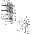
- Wing hinge flap 11 An essential part of the wing hinge 33 is a Wing hinge flap 11, which has a bottom 11 '' on one wing surface shown rests. The bottom is with two Provide webs 12, 13, the distance shown in Figure 3 from each other and perpendicular to the wing contact surface of the floor 11 '' or project to the wing. Between Web 12, 13 is a clamping plate 16 in an intermediate space 22 arranged, which engages with fitting bolts 35 in the wing and it is to be fastened with fastening screws 36. A vigorous tightening of the fastening screws 36 presses the Bottom of the sash hinge 11 firmly against the window sash and thus jams the wing hinge flap 11.
- the arrows 37 mean that the wing hinge flap 11 is horizontal parallel to the sash level in the adjustment directions 17, 18 can be adjusted according to FIG.
- the adjustment will by the adjustment means 19 shown in FIGS. 3 and 4 causes.
- the adjustment means 19 consist essentially of an adjusting screw 38 which with its head 38 'in a Recess 39 of the flap hinge 11 is rotatably adjustable, however axially immovable is fixed to the sash hinge 11.
- a another essential part of the screw adjustment device 19 is a nut 40 which is attached to the clamping plate 16 is.
- Prerequisite for such Adjustment is that the fastening screws 38 move allow the wing hinge flap 11, for example because they were loosened accordingly.
- An adjustment of the Wing hinge flap 11 causes a corresponding adjustment of the wing, because the frame part coupled with the wing hinge 33 25 on the frame is fixed to the frame.
- the cap 20 is present, with their Ends 20 'and 20' 'on the wing hinge flap 11 is fixed.
- the wing hinge flap 11 has the pivot bearing on its turned end 11 'a connecting web 21, which is from the ground of the wing hinge tab 11 projects in the same direction as the webs 12, 13, i.e. perpendicular to the wing.
- the connecting bridge 21 is in the area of the connection to the ends 12 ', 13' the bridges 12, 13 as high as these ends.
- Fig.1 shows that the webs 12, 13 lie with their outer edges in the same plane, like the outer edge of the connecting web 21 '.
- the connecting bridge 21 is semicircular round and thus designed the end 11 'of the wing hinge flap 11.
- the connecting web 21 has a passage opening, which is closed by a plug 23 is. The plug 23 is removed when access to the screw adjustment means 19 should be.
- the ends 12 ′′, 13 ′′ are in one piece with a bearing sleeve 24 connected with each other.
- the bearing sleeve 24 encloses the pivot bearing pin 15, which is arranged in a bearing bush 41 is.
- Their outside diameter corresponds to the inside diameter the bearing sleeve 24.
- the outer circumference of the bearing sleeve 24 becomes U-shaped trained end 20 '' of the cap 20 clasped.
- the cap 20 is arranged between the webs 12, 13 of the sash hinge 11 and their outer surfaces lie according to Figure 1 with the outer surfaces or edges of the webs 12, 13 flush.
- the Cap 20 matched that the webs 12,13 from their ends 12 '', 13 '' on the pivot bearing side to their ends 12 ', Taper 13 '.
- the end 20 'of the cap 20 is on the connecting web 21 set.
- the connecting bridge is appropriate for this the dashed line 42 in FIG. 3 is correspondingly thinner, so that there is an undercut 43 in which the Cap end 20 'are used with an angle 44 can so that the outer surface of the cap 20 with the outer wall as abutment 45 of the cap 20 is approximately flush.
- the end 20 '' of the cap 20 is with the wing band cap 11 locked, for which purpose a locking projection 46 and the cap 20 has a corresponding receptacle on its U-web 47.
- the latching is in the space 48 between the Bearing sleeve 24 and the frame part 25 and is closed Wings accordingly inaccessible.
- a wing flap is also inaccessible 11 one-piece coupling projection 27, which is in a coupling recess 26 of the frame band 25 engages.
- the vertical to Plane height of the coupling projection 27 corresponds approximately to its thickness which can be seen in FIG.
- the clear height of the coupling recess 26 is matched to this, as can be seen from Fig.1. Because the tape on the right and to be struck on the left are in frame 25 two symmetrical to the vertical plane of symmetry in Fig.4 Coupling recesses 26 available.
- the frame band 25 is with a contact surface 49 on one Stripped frame, not shown, the outer surface determines the frame contact level 32 shown in FIG.
- the attachment of the frame part serve the illustrated Fastening screws 50 in connection with the fitting bolts 51. It can be seen that the wing hinge 33 facing Surface has a recess 34 which allows the wing hinge towards the wing or towards the frame offset. This results in a correspondingly more compact one and more resilient training of the tape.
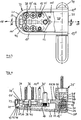
- Pivot bearing pin 15 is mounted with his for reasons of wear upper end in a bearing bush 41 and with its lower End in a bearing bushing 51. It rests on both of them Ends of the bolt 15 separating collar 52 on the lower Bearing bush 51 from. This is inside the pin bore 28 Height-adjustable by one end 51 ' a height-adjustable axle abutment 31 is seated.
- This Axial abutment 31 engages in an internal thread 54 of the bolt bore 28 and has a non-circular engagement recess 53, with which it is screw adjustable.
- Screw adjustment of the axis abutment 31 to a limited Height adjustment of the wing hinge 33 and thus of the wing, as symbolized by the two arrows 55.
- the band 10 is also in the directions of the Arrows 56 adjustable by an eccentric arrangement of the pivot bearing pin 15 within the bearing bush 41. This can be rotated within the bearing sleeve 24 and thereby moves the pivot axis 15 'on an arc about the longitudinal axis 57 of the frame hinge 25. A cap 58 engages over the bearing bush 41 above the web 12.
- the lower end 25 'of the frame band 25 is semicircular trained round.
- a cover wall 29 is provided for this purpose, which is formed with a clear distance to the pin bore 28.
- a through opening 59 is located in the cover wall 29 to the axle abutment 31.
- the free distance between the pin bore and the cover wall 29 is smaller than the height of the axle abutment 31.
- axle abutment 31 of the assembled tape practically not again can be screwed in because it is no longer in one accessible area e.g. is located near the frame system level 32. Rather, the axle abutment 31 hangs with its thread in the internal thread 54.
- Fig. 5 shows a modification of the hinge regarding the arrangement of a coupling projection 27 with respect to the Frame strap 25.
- the coupling projection 27 is at the height arranged between the frame band 25 and the pivot bearing pin 15 and engages in a coupling recess 26 'which between the two side surfaces of the frame band 25 continuously is trained.
- the clutch protrusion 27 when swiveling the sash open from the frame hinge 25 be moved regardless of whether the wing on the right or on the left.
- the swivel range can also be compared to the anti-lift device of Fig. 4 be comparatively large. As a result, the anti-lift device up to a swivel angle of approximately 45 degrees effective.
- the above arrangement of Coupling projection 27 between the pivot bearing pin 15 in the axis of symmetry of the frame band 25 the advantage that it as Locking abutment for the cap 20 can serve.
- the cap 20 is provided in its U-web 47 with a slot 47 'with which the cap when it is assembled with the wing flap 11 can be locked. This is achieved, for example, that the slit narrows in the area of its mouth is.
Landscapes
- Engineering & Computer Science (AREA)
- Mechanical Engineering (AREA)
- Hinges (AREA)
- Liquid Crystal (AREA)
Abstract
Description
- Fig.1
- eine perspektivische Übersichtsdarstellung des Tür- oder Fensterbandes,
- Fig.2
- einen Längsschnitt durch einen Schwenklagerbolzen quer zum Flügel,
- Fig.3
- eine Ansicht des Bandes senkrecht zum Flügel mit teilweise ausgebrochen dargestellter Kappe,
- Fig.4
- den Querschnitt IV-IV der Fig.3, und
- Fig.5
- eine der Fig.4 entsprechende Darstellung mit einer Abänderung im Bereich des Rahmenbands.
Claims (18)
- Tür- oder Fensterband (10), mit einem an einem Tür- oder Fensterflügel anliegenden Flügelbandlappen (11), der mittels beabstandet paralleler, zum Flügel vertikaler Stege (12,13) an einem Schwenklagerbolzen (15) angelenkt und dazu quer am Flügel verstellbar ist, mit einer zwischen den Stegen (12,13) angeordneten Klemmplatte (16), die unverschieblich am Flügel zu befestigen ist und dabei den Flügelbandlappen (11) gegen den Flügel preßt, und mit in den Verstellrichtungen (17,18) zwischen dem Flügelbandlappen (11) und der Klemmplatte (16) wirkenden Schraubverstellmitteln (19), die von einer am Flügelbandlappen (11) befestigten Kappe (20) abgedeckt sind, dadurch gekennzeichnet, daß die Stege (12,13) des Flügelbandlappens (11) an ihren dem Schwenklagerbolzen (15) abgewandten Enden (12',13') mit einem Verbindungssteg (21) des Flügelbandlappens (11) fest miteinander verbunden sind, und daß der Verbindungssteg (21) den die Klemmplatte (16) aufnehmenden Zwischenraum (22) zumindest teilweise in den Verstellrichtungen (17,18) abschließt.
- Tür- oder Fensterband nach Anspruch 1, dadurch gekennzeichnet, daß der Verbindungssteg (21) ebenso hoch ist, wie die beabstandet parallelen Stege (12,13).
- Tür- oder Fensterband nach Anspruch 1 oder 2, dadurch gekennzeichnet, daß der Verbindungssteg (21) einstückig mit den beabstandet parallelen Stegen (12,13) ist.
- Tür- oder Fensterband nach einem der Ansprüche 1 bis 3, dadurch gekennzeichnet, daß der Verbindungssteg (21) das Ende (11') des Flügelbandlappens (11) über den Abstand zwischen den Stegen (12,13) abrundet.
- Tür- oder Fensterband nach einem der Ansprüche 1 bis 4, dadurch gekennzeichnet, daß der Verbindungssteg (21) eine bedarfsweise mit einem Stopfen (23) verschließbare Druchgriffsöffnung für die Schraubverstellmittel (19) aufweist.
- Tür- oder Fensterband nach einem der Ansprüche 1 bis 5, dadurch gekennzeichnet, daß der Verbindungssteg (21) ein Widerlager (45) für ein Ende (20') der Kappe (20) hat.
- Tür- oder Fensterband nach einem der Ansprüche 1 bis 6, dadurch gekennzeichnet, daß die schwenklagerseitigen Enden (12'',13'') der Stege (12,13) von einer den Schwenklagerbolzen (15) aufnehmenden Lagerhülse (24) fest miteinander verbunden sind.
- Tür- oder Fensterband nach einem der Ansprüche 1 bis 7, dadurch gekennzeichnet, daß das schwenklagerseitige Ende (20'') der Kappe (20) U-förmig ist und die Lagerhülse (24) umklammert.
- Tür- oder Fensterband nach einem der Ansprüche 1 bis 8, dadurch gekennzeichnet, daß die Kappe (20) an ihrem schwenklagerseitigen und/oder an ihrem schwenklagerabgewandten Ende (20',20'') verrastet ist.
- Tür- oder Fensterband nach einem der Ansprüche 1 bis 9, dadurch gekennzeichnet, daß der Flügelbandlappen (11) mit einem Rahmenband (25) mittels eines in eine Kupplungsausnehmung (26) eingreifenden Kupplungsvorsprungs (27) bei geschlossenem Flügel vertikal formschlüssig kuppelbar ist.
- Tür- oder Fensterband nach Anspruch 10, dadurch gekennzeichnet, daµ der Flügelbandlappen (11) einen Kupplungsvorsprung (27) und das Rahmenband (25) zwei für Rechts/Linksanschlag ausgelegte Kupplungsausnehmungen (26) aufweist.
- Tür- oder Fensterband nach Anspruch 10, dadurch gekennzeichnet, daß der Flügelbandlappen (11) einen Kupplungsvorsprung (27) hat, der in der Symmetrieebene des Rahmenbands (25) zwischen diesem und dem Schwenklagerbolzen (15) angeordnet ist sowie in eine einzige für Rechts/Linksanschlag ausgelegte Kupplungsausnehmung (26') eingreift.
- Tür- oder Fensterband nach einem der Ansprüche 10 bis 12, dadurch gekennzeichnet, daß die Kappe (20) mittels eines Schlitzes (47') auf den Kupplungsvorsprung (27) aufzustecken ist.
- Tür- oder Fensterband nach einem der Ansprüche 1 bis 13, dadurch gekennzeichnet, daß das Rahmenband (25) unterhalb einer durchgängigen Bolzenbohrung (28) mit einer diese abdeckenden, mit dem Band (25) starr verbundenen Abdeckwand (29) versehen ist, die bedarfsweise eine Durchgriffsöffnung (30) für ein in der Bolzenbohrung (28) höhenverstellbares Achsenwiderlager (31) aufweist.
- Tür- oder Fensterband nach Anspruch 14, dadurch gekennzeichnet, daß die Abdeckwand (29) mit freiem Abstand zur Bolzenbohrung (28) angeordnet und bis zu einer Rahmenanlageebene (32) ausgebildet ist.
- Tür- oder Fensterband nach Anspruch 14 oder 15, dadurch gekennzeichnet, daß der freie Abstand der Abdeckwand (29) zur Bolzenbohrung (28) so gering ist, daß das Achsenwiderlager (31) nicht aus einem Innengewinde (54) der Bolzenbohrung (28) herauszudrehen ist.
- Tür- oder Fensterband nach Anspruch 14, dadurch gekennzeichnet, daß das schwenklagerabgewandte Ende (11') des Flügelbandlappens (11) und die beiden Enden (25',25'') des Rahmenbandes (25) jeweils in gleicher Weise halbkreisförmig rund enden.
- Tür- oder Fensterband nach einem der Ansprüche 1 bis 17, dadurch gekennzeichnet, daß das Rahmenband (25) eine sich über die Höhe des Flügelbandes (33) erstreckende Aussparung (34) aufweist, die eine zum Flügel versetzte Anordnung des Flügelbandes (33) erlaubt.
Applications Claiming Priority (2)
| Application Number | Priority Date | Filing Date | Title |
|---|---|---|---|
| DE29721037U DE29721037U1 (de) | 1997-11-28 | 1997-11-28 | Tür- oder Fensterband |
| DE29721037U | 1997-11-28 |
Publications (3)
| Publication Number | Publication Date |
|---|---|
| EP0919686A2 true EP0919686A2 (de) | 1999-06-02 |
| EP0919686A3 EP0919686A3 (de) | 2001-03-21 |
| EP0919686B1 EP0919686B1 (de) | 2004-04-21 |
Family
ID=8049210
Family Applications (1)
| Application Number | Title | Priority Date | Filing Date |
|---|---|---|---|
| EP98122090A Expired - Lifetime EP0919686B1 (de) | 1997-11-28 | 1998-11-21 | Tür- oder Fensterband |
Country Status (4)
| Country | Link |
|---|---|
| EP (1) | EP0919686B1 (de) |
| DE (2) | DE29721037U1 (de) |
| HU (1) | HU219418B (de) |
| PL (1) | PL186418B1 (de) |
Cited By (11)
| Publication number | Priority date | Publication date | Assignee | Title |
|---|---|---|---|---|
| EP1091067A1 (de) * | 1999-10-04 | 2001-04-11 | Niemann, Hans Dieter | Drehband für Türen oder Fenster |
| EP0952291A3 (de) * | 1998-04-24 | 2003-01-29 | Hans Dieter Niemann | Tür- oder Fensterband |
| GB2444419A (en) * | 2004-05-28 | 2008-06-04 | Trojan Hardware & Designs Ltd | Hinge with leaf and spindle blocking access to fixing screws |
| EP1223275A3 (de) * | 2001-01-15 | 2008-09-03 | Niemann, Hans Dieter | Band für Türen oder Fenster |
| WO2011064100A1 (de) * | 2009-11-27 | 2011-06-03 | Dr. Hahn Gmbh & Co. Kg | Bandteil eines scharnierbandes sowie verfahren zur befestigung eines bandteils |
| FR2993299A1 (fr) * | 2012-07-10 | 2014-01-17 | Monin | Paumelle pour huisserie reglable en trois dimensions |
| EP2345787A3 (de) * | 2010-01-14 | 2014-01-22 | Simonswerk, Gesellschaft mit beschränkter Haftung | Türband für Aluminiumtüren |
| EP2345786A3 (de) * | 2010-01-14 | 2014-01-22 | Simonswerk, Gesellschaft mit beschränkter Haftung | Türband für Aluminiumtüren |
| EP2492424A3 (de) * | 2011-02-23 | 2014-10-08 | Altura Leiden Holding B.V. | Verbindungsvorrichtung einer Trennwand, insbesondere Duschtrennwand |
| EP2862997A1 (de) * | 2013-10-18 | 2015-04-22 | Joseph Talpe | Scharnieranordnung |
| EP3447223A1 (de) * | 2009-11-27 | 2019-02-27 | Dr. Hahn GmbH & Co. KG | Bandteil eines scharnierbandes |
Citations (1)
| Publication number | Priority date | Publication date | Assignee | Title |
|---|---|---|---|---|
| DE29622639U1 (de) | 1996-11-05 | 1997-04-17 | Haps + Sohn GmbH + Co KG, 42551 Velbert | Tür- oder Fensterband |
Family Cites Families (7)
| Publication number | Priority date | Publication date | Assignee | Title |
|---|---|---|---|---|
| CH392314A (de) * | 1962-04-12 | 1965-05-15 | Eugen Schneider Ernst | Gelenkband für Türen, Fenster und dergleichen |
| FR2339044A1 (fr) * | 1976-01-22 | 1977-08-19 | Laurent Philippe | Paumelle reglable en trois directions |
| DE3245205A1 (de) * | 1981-12-09 | 1983-07-21 | F. Hesterberg & Söhne GmbH & Co KG, 5828 Ennepetal | Scharnier fuer tueren von fahrzeugkofferaufbauten, containern und dergleichen mit einer zollsicherung |
| DE3406984C2 (de) * | 1984-02-13 | 1993-11-18 | Scharwaechter Gmbh Co Kg | Aushängbares Flügelscharnier |
| DE3546253A1 (de) * | 1985-12-28 | 1987-07-02 | Hahn Gmbh & Co Kg Dr | Band fuer tueren, fenster und dergleichen |
| DE9200563U1 (de) * | 1992-01-18 | 1992-04-02 | Breuer & Schmitz, 5650 Solingen | Dreidimensional verstellbares Aufschraubband für Tür- oder Fensterflügel |
| DE9413892U1 (de) * | 1994-08-27 | 1995-12-21 | Dr. Hahn GmbH & Co. KG., 41189 Mönchengladbach | Band für Türen, Fenster u.dgl. |
-
1997
- 1997-11-28 DE DE29721037U patent/DE29721037U1/de not_active Expired - Lifetime
-
1998
- 1998-11-21 EP EP98122090A patent/EP0919686B1/de not_active Expired - Lifetime
- 1998-11-21 DE DE59811232T patent/DE59811232D1/de not_active Expired - Lifetime
- 1998-11-27 HU HU9802756A patent/HU219418B/hu unknown
- 1998-11-27 PL PL98329964A patent/PL186418B1/pl unknown
Patent Citations (1)
| Publication number | Priority date | Publication date | Assignee | Title |
|---|---|---|---|---|
| DE29622639U1 (de) | 1996-11-05 | 1997-04-17 | Haps + Sohn GmbH + Co KG, 42551 Velbert | Tür- oder Fensterband |
Cited By (14)
| Publication number | Priority date | Publication date | Assignee | Title |
|---|---|---|---|---|
| EP0952291A3 (de) * | 1998-04-24 | 2003-01-29 | Hans Dieter Niemann | Tür- oder Fensterband |
| EP1091067A1 (de) * | 1999-10-04 | 2001-04-11 | Niemann, Hans Dieter | Drehband für Türen oder Fenster |
| EP1091066A3 (de) * | 1999-10-04 | 2001-08-01 | Niemann, Hans Dieter | Drehband für Türen oder Fenster |
| EP1223275A3 (de) * | 2001-01-15 | 2008-09-03 | Niemann, Hans Dieter | Band für Türen oder Fenster |
| GB2444419A (en) * | 2004-05-28 | 2008-06-04 | Trojan Hardware & Designs Ltd | Hinge with leaf and spindle blocking access to fixing screws |
| GB2444419B (en) * | 2004-05-28 | 2008-12-03 | Trojan Hardware & Designs Ltd | Hinge arrangements |
| WO2011064100A1 (de) * | 2009-11-27 | 2011-06-03 | Dr. Hahn Gmbh & Co. Kg | Bandteil eines scharnierbandes sowie verfahren zur befestigung eines bandteils |
| EP3447223A1 (de) * | 2009-11-27 | 2019-02-27 | Dr. Hahn GmbH & Co. KG | Bandteil eines scharnierbandes |
| EP2504511B1 (de) * | 2009-11-27 | 2020-02-19 | Dr. Hahn GmbH & Co. KG | Bandteil eines scharnierbandes |
| EP2345787A3 (de) * | 2010-01-14 | 2014-01-22 | Simonswerk, Gesellschaft mit beschränkter Haftung | Türband für Aluminiumtüren |
| EP2345786A3 (de) * | 2010-01-14 | 2014-01-22 | Simonswerk, Gesellschaft mit beschränkter Haftung | Türband für Aluminiumtüren |
| EP2492424A3 (de) * | 2011-02-23 | 2014-10-08 | Altura Leiden Holding B.V. | Verbindungsvorrichtung einer Trennwand, insbesondere Duschtrennwand |
| FR2993299A1 (fr) * | 2012-07-10 | 2014-01-17 | Monin | Paumelle pour huisserie reglable en trois dimensions |
| EP2862997A1 (de) * | 2013-10-18 | 2015-04-22 | Joseph Talpe | Scharnieranordnung |
Also Published As
| Publication number | Publication date |
|---|---|
| EP0919686B1 (de) | 2004-04-21 |
| DE59811232D1 (de) | 2004-05-27 |
| DE29721037U1 (de) | 1999-04-22 |
| HU219418B (hu) | 2001-04-28 |
| HU9802756D0 (en) | 1999-01-28 |
| HUP9802756A1 (hu) | 1999-10-28 |
| PL329964A1 (en) | 1999-06-07 |
| PL186418B1 (pl) | 2004-01-30 |
| EP0919686A3 (de) | 2001-03-21 |
Similar Documents
| Publication | Publication Date | Title |
|---|---|---|
| EP0919686B1 (de) | Tür- oder Fensterband | |
| EP0678636B1 (de) | Verbindungsvorrichtung für den Einbau des Flügels eines Wohndachfensters in den Futterkasten | |
| DE3605434A1 (de) | Befestigung fuer ein mit einem tuerfeststeller baulich vereinigtes tuerscharnier | |
| DE102011006023B3 (de) | Verstellbares Scharnierband | |
| EP1215357B1 (de) | Bandanordnung für Türen, Fenster und dergleichen | |
| DE202006002236U1 (de) | Band für Türen, Fenster o.dgl. | |
| EP0164381A1 (de) | Scharnierkonstruktion für einen, wahlweise um zwei schwenkachsen, drehbaren flügel | |
| EP1023515B1 (de) | Tür- oder fensterband | |
| EP3887631B1 (de) | Bandlappen und band zur um eine scharnierachse scharniergelenkigen verbindung eines flügels mit einem rahmen | |
| EP0861953A1 (de) | Betätigungshandhabe | |
| DE3228933A1 (de) | Drehzapfenlager fuer tueren, insbesondere fuer pendeltueren | |
| EP2385200B1 (de) | Beschlagteil zur Befestigung an einer C-förmigen Beschlagteilnut | |
| EP0748911B1 (de) | Treibstangen-Verschlussvorrichtung für die Flügel von Fenstern, Türen od. dgl. | |
| EP1267025B1 (de) | Fenster oder Fenstertür | |
| DE19918283B4 (de) | Tür- oder Fensterdrehband | |
| EP1560996A1 (de) | Beschlaganordnung für glastüren | |
| EP1255005B1 (de) | Riegelbeschlag | |
| DE29615631U1 (de) | Sicherungseinrichtung | |
| EP1386050B1 (de) | Halteelement zum halten einer führungsschiene für schiebetüren | |
| DE4323939C5 (de) | Gelenkvorrichtung, insbesondere für Drehkipptür oder -fenster | |
| EP0677631B2 (de) | Betätigungsvorrichtung für ein Verschlussgetriebe | |
| EP4105420B1 (de) | Band fuer eine tuer oder ein fenster | |
| EP1388628A2 (de) | Scharnierband mit einer winkel- und höheneinstellbaren Hebe-Senkvorrichtung für Türen oder Fenster | |
| EP1405975A1 (de) | Einstellbare Türbandanordnung | |
| DE202006009972U1 (de) | Band für Fenster, Türen o.dgl. |
Legal Events
| Date | Code | Title | Description |
|---|---|---|---|
| PUAI | Public reference made under article 153(3) epc to a published international application that has entered the european phase |
Free format text: ORIGINAL CODE: 0009012 |
|
| AK | Designated contracting states |
Kind code of ref document: A2 Designated state(s): DE FR GB IT |
|
| AX | Request for extension of the european patent |
Free format text: AL;LT;LV;MK;RO;SI |
|
| PUAL | Search report despatched |
Free format text: ORIGINAL CODE: 0009013 |
|
| AK | Designated contracting states |
Kind code of ref document: A3 Designated state(s): AT BE CH CY DE DK ES FI FR GB GR IE IT LI LU MC NL PT SE |
|
| AX | Request for extension of the european patent |
Free format text: AL;LT;LV;MK;RO;SI |
|
| 17P | Request for examination filed |
Effective date: 20010629 |
|
| AKX | Designation fees paid |
Free format text: DE FR GB IT |
|
| 17Q | First examination report despatched |
Effective date: 20030411 |
|
| GRAP | Despatch of communication of intention to grant a patent |
Free format text: ORIGINAL CODE: EPIDOSNIGR1 |
|
| GRAS | Grant fee paid |
Free format text: ORIGINAL CODE: EPIDOSNIGR3 |
|
| GRAA | (expected) grant |
Free format text: ORIGINAL CODE: 0009210 |
|
| AK | Designated contracting states |
Kind code of ref document: B1 Designated state(s): DE FR GB IT |
|
| REG | Reference to a national code |
Ref country code: GB Ref legal event code: FG4D Free format text: NOT ENGLISH |
|
| REF | Corresponds to: |
Ref document number: 59811232 Country of ref document: DE Date of ref document: 20040527 Kind code of ref document: P |
|
| GBT | Gb: translation of ep patent filed (gb section 77(6)(a)/1977) |
Effective date: 20040721 |
|
| ET | Fr: translation filed | ||
| PLBE | No opposition filed within time limit |
Free format text: ORIGINAL CODE: 0009261 |
|
| STAA | Information on the status of an ep patent application or granted ep patent |
Free format text: STATUS: NO OPPOSITION FILED WITHIN TIME LIMIT |
|
| 26N | No opposition filed |
Effective date: 20050124 |
|
| REG | Reference to a national code |
Ref country code: FR Ref legal event code: PLFP Year of fee payment: 18 |
|
| REG | Reference to a national code |
Ref country code: FR Ref legal event code: PLFP Year of fee payment: 19 |
|
| REG | Reference to a national code |
Ref country code: FR Ref legal event code: PLFP Year of fee payment: 20 |
|
| PGFP | Annual fee paid to national office [announced via postgrant information from national office to epo] |
Ref country code: DE Payment date: 20171127 Year of fee payment: 20 Ref country code: FR Payment date: 20171121 Year of fee payment: 20 |
|
| PGFP | Annual fee paid to national office [announced via postgrant information from national office to epo] |
Ref country code: GB Payment date: 20171123 Year of fee payment: 20 Ref country code: IT Payment date: 20171124 Year of fee payment: 20 |
|
| REG | Reference to a national code |
Ref country code: DE Ref legal event code: R071 Ref document number: 59811232 Country of ref document: DE |
|
| REG | Reference to a national code |
Ref country code: GB Ref legal event code: PE20 Expiry date: 20181120 |
|
| PG25 | Lapsed in a contracting state [announced via postgrant information from national office to epo] |
Ref country code: GB Free format text: LAPSE BECAUSE OF EXPIRATION OF PROTECTION Effective date: 20181120 |