EP0917401A2 - Dispositif pour le refroidissement d'un four micro-ondes avec des lampes chauffantes additionnelles - Google Patents
Dispositif pour le refroidissement d'un four micro-ondes avec des lampes chauffantes additionnelles Download PDFInfo
- Publication number
- EP0917401A2 EP0917401A2 EP98121222A EP98121222A EP0917401A2 EP 0917401 A2 EP0917401 A2 EP 0917401A2 EP 98121222 A EP98121222 A EP 98121222A EP 98121222 A EP98121222 A EP 98121222A EP 0917401 A2 EP0917401 A2 EP 0917401A2
- Authority
- EP
- European Patent Office
- Prior art keywords
- microwave oven
- cooling
- cavity
- airflow
- lighting lamps
- Prior art date
- Legal status (The legal status is an assumption and is not a legal conclusion. Google has not performed a legal analysis and makes no representation as to the accuracy of the status listed.)
- Granted
Links
- 238000001816 cooling Methods 0.000 title claims abstract description 104
- 238000010438 heat treatment Methods 0.000 title description 19
- 238000010411 cooking Methods 0.000 claims description 15
- 239000000779 smoke Substances 0.000 description 8
- 235000013305 food Nutrition 0.000 description 3
- XLYOFNOQVPJJNP-UHFFFAOYSA-N water Substances O XLYOFNOQVPJJNP-UHFFFAOYSA-N 0.000 description 3
- 238000000034 method Methods 0.000 description 2
- 235000013550 pizza Nutrition 0.000 description 2
- 230000000052 comparative effect Effects 0.000 description 1
- 238000010276 construction Methods 0.000 description 1
- 230000005611 electricity Effects 0.000 description 1
- 230000008020 evaporation Effects 0.000 description 1
- 238000001704 evaporation Methods 0.000 description 1
- 235000013611 frozen food Nutrition 0.000 description 1
- 229910052736 halogen Inorganic materials 0.000 description 1
- 150000002367 halogens Chemical class 0.000 description 1
- 238000009434 installation Methods 0.000 description 1
- 238000002844 melting Methods 0.000 description 1
- 230000008018 melting Effects 0.000 description 1
- 239000008267 milk Substances 0.000 description 1
- 210000004080 milk Anatomy 0.000 description 1
- 235000013336 milk Nutrition 0.000 description 1
Images


Classifications
-
- F—MECHANICAL ENGINEERING; LIGHTING; HEATING; WEAPONS; BLASTING
- F24—HEATING; RANGES; VENTILATING
- F24C—DOMESTIC STOVES OR RANGES ; DETAILS OF DOMESTIC STOVES OR RANGES, OF GENERAL APPLICATION
- F24C7/00—Stoves or ranges heated by electric energy
-
- H—ELECTRICITY
- H05—ELECTRIC TECHNIQUES NOT OTHERWISE PROVIDED FOR
- H05B—ELECTRIC HEATING; ELECTRIC LIGHT SOURCES NOT OTHERWISE PROVIDED FOR; CIRCUIT ARRANGEMENTS FOR ELECTRIC LIGHT SOURCES, IN GENERAL
- H05B6/00—Heating by electric, magnetic or electromagnetic fields
- H05B6/64—Heating using microwaves
- H05B6/642—Cooling of the microwave components and related air circulation systems
- H05B6/6423—Cooling of the microwave components and related air circulation systems wherein the microwave oven air circulation system is also used as air extracting hood
-
- H—ELECTRICITY
- H05—ELECTRIC TECHNIQUES NOT OTHERWISE PROVIDED FOR
- H05B—ELECTRIC HEATING; ELECTRIC LIGHT SOURCES NOT OTHERWISE PROVIDED FOR; CIRCUIT ARRANGEMENTS FOR ELECTRIC LIGHT SOURCES, IN GENERAL
- H05B6/00—Heating by electric, magnetic or electromagnetic fields
- H05B6/64—Heating using microwaves
- H05B6/6444—Aspects relating to lighting devices in the microwave cavity
-
- H—ELECTRICITY
- H05—ELECTRIC TECHNIQUES NOT OTHERWISE PROVIDED FOR
- H05B—ELECTRIC HEATING; ELECTRIC LIGHT SOURCES NOT OTHERWISE PROVIDED FOR; CIRCUIT ARRANGEMENTS FOR ELECTRIC LIGHT SOURCES, IN GENERAL
- H05B6/00—Heating by electric, magnetic or electromagnetic fields
- H05B6/64—Heating using microwaves
- H05B6/647—Aspects related to microwave heating combined with other heating techniques
- H05B6/6482—Aspects related to microwave heating combined with other heating techniques combined with radiant heating, e.g. infrared heating
Definitions
- This invention relates to a cooling system for a microwave oven, and more particularly to an apparatus for cooling a microwave oven having lighting lamps inside the cavity.
- a microwave oven generates microwave out of using electricity, and the microwave impinges into cooking stuff, causing molecular motion in the interior of the stuff, and heats the foodstuff.
- the microwave oven has been widely used for melting frozen food or heating food like milk to a desired degree because of advantages in using.
- the microwave oven has some disadvantages caused in using of the heating method, and it has some limit in its own generating capacity as well. So, it cannot be altogether appropriate for heating stuff.
- the conventional microwave oven cannot provide a good quality of cooking with rapidity because it uses microwave only as a heat source; that is to show a single way of heating by microwave and a certain limited output of power.
- the microwave oven as a heat source does not include various functions as a whole because the heater even the microwave oven having a heater, functions just as a simply additional heat source.
- the microwave oven To use lighting lamp as additional heat source, the microwave oven must provide lighting lamps with a high voltage to be able to cook foodstuff within a short time. But, this high voltage lighting lamp generates heat as much as a high voltage, which can heat stuff in a short time. Accordingly, it is necessary to propose an apparatus for cooling lighting lamp sufficiently. For example, this apparatus for cooling the lighting lamp must not damage on its own lighting lamp and its parts by light generated from the lighting lamp. Also, it is necessary to propose the apparatus for cooling the heating part sufficiently.
- the conventional microwave oven comprises a magnetron for generating the microwave and a cooling fan for cooling heat generating from a high voltage transformer so as to supply a high voltage to the magnetron.
- the object of this invention is to provide a cooling apparatus for cooling fully a microwave oven having lighting lamps using light energy as a heat source.
- a cooling apparatus for microwave oven comprises:
- the first cooling means and the second cooling means cool the microwave generating and supplying means and the lighting lamp sufficiently. Therefore, the microwave oven cools the heat generated by the lighting lamp of additional heat source, and adjusts for providing the desired cooking result.
- the lighting lamp of this invention is installed in the outer side of the upper part and the lower part in the cavity respectively.
- the first cooling means for cooling the lighting lamp comprises a upper cooling fan and a lower cooling fan so as to cool the lighting lamp installed on the upper part and the lower part in the cavity, respectively.
- An additional pair of cooling fans can cool the lighting lamp installed on the upper face and the lower face of the cavity.
- the airflow made by the upper cooling fan is guided to the upper lighting lamp through a plurality of the duct walls, the airflow passes through the draft grill installed in the front end of the microwave oven.
- the airflow passage by the duct walls include an inner intake part for sucking a part of the airflow into cavity and an inner exhaust part for exhausting the airflow from the cavity.
- the airflow is exhausted to the outside through inside of cavity. In this way, the airflow by the upper cooling fan can be possible to exhaust the inner air in the cavity sufficiently.
- the airflow made by the lower cooling fan comprises a lower duct arranged between the downside of cavity and an outer case of the microwave oven, and a lateral duct arranged between the lateral wall of the cavity and the outer case of the microwave oven.
- the airflow made by the cooling fan is guided to the lateral duct and is exhausted to the outside, thereby, the airflow, passing through the lateral duct, cools the lower lighting lamp.
- Fig. 1 shows the cooling apparatus for cooling lighting lamps installed an additional lighting lamp in the microwave oven called OTR (Over The Range).
- OTR Over The Range
- the upper lighting lamp 10 and the lower lighting lamp 12, which are a different heat source other than microwave, are mounted on the upside 4 and downside 6 of cavity.
- the light generated by the lighting lamps 10, 12 is sucked into the cavity 2 directly or by being reflected by the reflecting plates 14, 16 positioned the outside of the lighting lamps 10, 12.
- the cooling fans 20, 22 for cooling heat by the lighting lamps 10, 12 are mounted to supply airflow for cooling towards the lighting lamps 10, 12
- the cooling fans 20, 22 for cooling the lighting lamps 10, 12 comprises the upper cooling fan 20 mounted to the upper face of the cavity for cooling the lighting lamp 10 mounted to the upper face of the cavity 4 and the lower cooling fan 22 mounted to the lower face of the cavity for cooling the lighting lamp 12 mounted to the lower face of the cavity 6.
- the cavity includes a front chamber 8 at one side of cavity and the parts for generating microwave, such as a high voltage transformer and a magnetron and so on, inside of the front chamber.
- the cooling fan 24 for cooling heat is mounted to the one side of the front chamber 8, by which the airflow is made.
- the airflow cools all parts in the cavity, and then exhausts vapor and smoke inside cavity through the exhaust part.
- an exhaust motor 26 is mounted on the upper back face of the microwave oven called OTR (Over The Range) and exhausts smoke towards the inner part of the microwave oven from its outer part.
- a draft grill part 30 for exhausting a heating air or smoke made by the gas oven range is mounted on the upper face of the microwave oven called OTR.
- the draft grill part 30 is mounted on the upside of the microwave oven to pass the air, or may be mounted in the front face or the upper face or in the back face of the microwave oven.
- the upper cooling fan 20 intakes the outside air through the intake part 31 of the draft grill part 30 mounted to the front upper end face of the microwave oven and, which exhausts the airflow A toward the upper lighting lamp 10.
- the upper cooling fan 20 exhausts the airflow for cooling the upper lighting lamp 10 sufficiently and does not limit sucking of the outside air through the draft grill part 30 mounted in front face of the microwave oven.
- the cooling fan exhausts the airflow cooling the upper lighting lamp 10 and intakes the airs through the draft grill part. Accordingly, it can not be limited by installation place, the kind of the cooling fan.
- the airflow made by the upper cooling fan 20 cools the lighting lamp and the its parts through the upper lighting lamp 10 basically.
- the upper cooling fan 20 cools the upper lighting lamp 10, its own upper lighting lamp 10 and the connected part 11 of the cable 13 to supply the power to the upper lighting lamp 10 and the reflecting plate 14 mounted around the upper lighting lamp 10 cools justly.
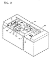
- the part of the airflow cooling the upper lighting lamp 10 is exhausted to the outside through the exhaust part 32 mounted in the draft drill part 30 as shown in Fig. 2. And, the part of the airflow passes toward interior of the cavity through the inner intake part 33 having a plurality of the draft holes.
- the airflow entered inside the cavity comes out through the inner exhaust part having a plurality of the draft holes mounted to the upper face of the cavity.
- the airflow coming out the cavity 2 through the inner exhaust part 34 is exhausted to the front face of the microwave oven through the draft grill part 30.
- the airflow made by the upper cooling fan 20 passes the upper lighting lamp 10 and, is supplied to the interior of the cavity through the inner intake part 33 or is exhausted to the outside of the microwave oven through the exhaust part 34.
- the airflow made by the upper cooling fan 20 is guided by a plurality of the duct walls Wa, Wb, Wc, Wd and We arranged to the front of the cavity 2.
- the airflow made by the upper cooling fan 20 is guided by the duct wall We to the upper lighting lamp 10.
- the airflow passes the upper lighting lamp 10 and cools the upper lighting lamp 10 which is guided by the duct walls Wc, Wd and is exhausted to the front face of the microwave oven through the draft grill part 30.
- the airflow passing inside of the cavity through the inner intake part 33 between the duct wall Wb and Wc is exhausted to the front face of the microwave oven through the draft grill part 30 and the inner exhaust part 34 between the duct wall Wa and the duct wall Wb.
- the course of the airflow is as follows.
- the airflow made by the upper cooling fan 20 is guided by the duct walls Wa, Wb, Wc, Wd, and We cooling the upper lighting lamp 10 through the upper lighting lamp 10, is exhausted to the outside of the microwave oven through the draft grill part 30. Or, the airflow enters inside of the cavity 2 and is exhausted to outside of the microwave oven through the draft grill part 30. In this way, the airflow made by the upper cooling fan 20 cools the upper lighting lamp 10 and is exhausted outward microwave oven through draft grill part in cavity.
- the airflow by the upper cooling fan 20 can cool the upper lighting lamp 10 and also vary the duct wall in many ways.
- the lower cooling fan 22 is mounted to the lower part of the front chamber 8 for cooling the lower lighting lamp 12 mounted on the lower face 6 of the cavity 2. Therefore, to intake the air of the outside of the microwave oven, it is composed that the cooling airflow passes the lower lighting lamp 12.
- the airflow made by the lower cooling fan 22 passes between the lower face 6 of the cavity 2 and the lower face 18 of the microwave oven.
- the lower duct 40 is a passage arranged between the lower face 6 of the cavity 2 and the lower face 18 of the outer case of the microwave oven.
- the lower duct 40 is connected to the lateral duct 42 arranged between the lateral wall 5 of cavity 2 and the lateral wall 19 of the outer case of the microwave oven.
- the heating part of the lower lighting lamp 12 includes its own lighting lamp and its parts such as the connected part of the power supply in the lamp and the reflecting plate 16 and so on.
- the airflow cooling the lighting lamp 12 is exhausted outward through the lower duct 40 and the lateral duct 42.
- the airflow made by the lower cooling fan 22 moves toward the upper part through the lateral duct 42 arranged between the lateral face 5 of the cavity 2 and the lateral wall 19 of the outer case of the microwave oven.
- the airflow moving toward the upper part can be exhausted to the front face of the microwave oven through the draft grill part 30, and also be exhausted to the outside through an exhausting course by the exhaust motor 26 as shown in Fig. 3 as in the conventional art.
- the cooling airflow made by the lower cooling fan 22 may not exhaust just outside through the upper part.
- another exhaust hole is mounted to the side wall 19 of the outer case opposite to the lower cooling fan 22; and exhausts to the outside the airflow through the exhaust hole.
- the airflow made by the lower cooling fan 22 is guided to the interior of the cavity 2. Accordingly, it guides the airflow to assist the airflow of the cavity.
- the cooling fan 20 is equal to the construction of the conventional cooling fan substantially, which intakes the air from outside of the microwave oven, and cools the parts mounted to the front chamber 8. That is, the cooling fan 20 emits the heat generating from the parts generating the microwave such as magnetron and a high voltage transformer and so on.
- the airflow C made by the cooling fan 24 intakes the air from outside through the draft grill part 30 or through the back wall 17 of the microwave oven as shown in Fig. 2. Such the outside air is sucked into cavity after cooling the parts, such as a magnetron and a high voltage transformer, mounted to the front chamber 8.
- the inner exhaust part 34 comprises a plurality of the draft holes mounted in the upper face 4 of the cavity 2 substantially, the draft hole is joined the interior of the cavity.
- An additional draft hole can be formed to the lateral face 5 of the cavity 2, the additional draft hole exhausts outward the airflow sucked into cavity by the cooling fan 24.
- the microwave oven called OTR comprises an exhaust motor 26 mounted in the downside of microwave oven to intake the heat and smoke by generating in microwave oven.
- the exhaust motor 26 intakes the air of the lower part through the intake part (not shown) arranged to the lower face 18 of the microwave oven.
- the sucked air is described as C.
- the draft grill part 30 can be mounted to the front upper face of the microwave oven or to the back face 17 of the microwave oven as well.
- the sucked air moved by the exhaust motor 26 into the interior of the microwave oven is heat and smoke and is moved to the upper part through the lower duct 40 and the lateral duct 42, and then is exhausted to the outside.
- Such air, moved to the interior of the microwave oven made by the exhaust motor 26, can be exhausted to outside by the exhaust motor 26 through the conventional course.
- the airflow moves to the upper part along with the right lateral face of the microwave oven, and thereby is exhausted to the outside of the microwave oven through the back face 17 of the microwave oven or draft grill part 30 of the upper face of the microwave oven like drawn by the dotted line in Fig. 1.
- Such the exhausted airflow is exhausted to the outside through the hood apparatus mounted in the kitchen.
- the microwave oven of this invention includes an additional lighting lamps 10, 12 providing a heat source.
- the lighting lamps may include a halogen lamp employing radiant energy as visible ray and infrared ray.
- the lighting lamps 10, 12 are mounted to one side of the cavity 2, and more particularly to the upper face 4 of the cavity 2 and/or the lower face 6 of the cavity. Because the microwave oven provides the light generated by the lighting lamps 10, 12 into the cavity 2 supply, namely because the microwave oven uses the lighting lamps 10, 12 as a heat source, which produced heat by the lighting lamp and the reflecting plates 14, 16.
- the microwave oven includes the cooling fans 20, 22 for cooling lighting lamps 10, 12. Thus, the airflow by the cooling fans 20, 22 cools the lighting lamp.
- This invention is to provide to a cooking apparatus such lighting lamps radiating visible ray and infrared ray having a certain wavelength as a proper proportion and a microwave as a heat source selectively. In this way, the cooling apparatus cools the heat made by the lighting lamps effectively.
- the cooling apparatus includes the airflow made by a plurality of cooling fans toward the upper lighting lamp and the lower lighting lamp.
- the airflow that cools the lighting lamp is guided to the interior of the cavity, which is exhausted to the outside.
- the microwave oven includes an additional lighting lamp and the reliability of the lighting lamp can be increased, so that this invention is to provide the microwave oven for using and a various cooking function for a long period.
Applications Claiming Priority (2)
| Application Number | Priority Date | Filing Date | Title |
|---|---|---|---|
| KR9760246 | 1997-11-15 | ||
| KR1019970060246A KR100301904B1 (ko) | 1997-11-15 | 1997-11-15 | 할로겐램프를구비한전자레인지의냉각장치 |
Publications (3)
| Publication Number | Publication Date |
|---|---|
| EP0917401A2 true EP0917401A2 (fr) | 1999-05-19 |
| EP0917401A3 EP0917401A3 (fr) | 2000-03-29 |
| EP0917401B1 EP0917401B1 (fr) | 2006-05-03 |
Family
ID=19524811
Family Applications (1)
| Application Number | Title | Priority Date | Filing Date |
|---|---|---|---|
| EP98121222A Expired - Lifetime EP0917401B1 (fr) | 1997-11-15 | 1998-11-06 | Dispositif pour le refroidissement d'un four micro-ondes avec des lampes chauffantes additionnelles |
Country Status (5)
| Country | Link |
|---|---|
| US (1) | US6005235A (fr) |
| EP (1) | EP0917401B1 (fr) |
| KR (1) | KR100301904B1 (fr) |
| CN (1) | CN1201118C (fr) |
| DE (1) | DE69834379T2 (fr) |
Cited By (4)
| Publication number | Priority date | Publication date | Assignee | Title |
|---|---|---|---|---|
| DE10203607A1 (de) * | 2002-01-30 | 2003-07-31 | Bsh Bosch Siemens Hausgeraete | Lichtwellenofen mit Kühlkanal |
| EP1545161A2 (fr) * | 2003-12-18 | 2005-06-22 | Daewoo Electronics Corporation | Structure de refroidissement pour porte de four à microondes utilisable pour les pizzas. |
| WO2008060113A1 (fr) * | 2006-11-15 | 2008-05-22 | Lg Electronics Inc. | Dispositif de cuisson |
| EP1243164B1 (fr) * | 1999-12-27 | 2008-05-28 | Lg Electronics Inc. | Four a micro-ondes encastre |
Families Citing this family (15)
| Publication number | Priority date | Publication date | Assignee | Title |
|---|---|---|---|---|
| KR20000003800U (ko) * | 1998-07-29 | 2000-02-25 | 구자홍 | 전자레인지의 할로겐램프 냉각구조 |
| US6262668B1 (en) | 1999-01-04 | 2001-07-17 | Emc Corporation | Detection system for an electronic enclosure |
| US6407671B1 (en) * | 1999-01-04 | 2002-06-18 | Emc Corporation | Detection system for an electronic enclosure |
| US6344637B2 (en) * | 1999-12-18 | 2002-02-05 | Lg Electronics Inc. | Cooling system for built-in microwave oven |
| KR100402492B1 (ko) * | 2000-11-10 | 2003-10-22 | 주식회사 엘지이아이 | 전자레인지의 히터가열시스템 |
| DE60132423T2 (de) * | 2000-11-30 | 2009-01-15 | Lg Electronics Inc. | Heizvorrichtung für einen Mikrowellenherd |
| KR100402495B1 (ko) * | 2000-11-30 | 2003-10-22 | 주식회사 엘지이아이 | 전자레인지의 히터시스템 |
| US6987252B2 (en) * | 2001-01-11 | 2006-01-17 | General Electric Company | Speedcooking oven including convection/bake mode and microwave heating |
| US6521870B2 (en) * | 2001-01-11 | 2003-02-18 | General Electric Company | Thermal/convection oven including halogen lamps |
| KR20040068681A (ko) * | 2003-01-27 | 2004-08-02 | 삼성전자주식회사 | 전자렌지 |
| WO2011002054A1 (fr) * | 2009-07-03 | 2011-01-06 | シャープ株式会社 | Appareil de cuisson par chauffage |
| WO2011028724A1 (fr) | 2009-09-01 | 2011-03-10 | Manitowoc Foodservice Companies, Llc. | Procédé et appareil pour ventiler un dispositif de cuisson |
| CN102235692A (zh) * | 2010-04-23 | 2011-11-09 | 乐金电子(天津)电器有限公司 | 一种微波炉 |
| EP3403468B1 (fr) * | 2016-01-14 | 2019-11-20 | Koninklijke Philips N.V. | Appareil de cuisine et procédé de surveillance de cuisson |
| DE102017009427A1 (de) * | 2017-10-11 | 2019-04-11 | Emz-Hanauer Gmbh & Co. Kgaa | Pyrolyse-Backofen mit einem Leuchtmodul |
Citations (5)
| Publication number | Priority date | Publication date | Assignee | Title |
|---|---|---|---|---|
| US4283614A (en) * | 1978-02-20 | 1981-08-11 | Matsushita Electric Industrial Co., Ltd. | Cooking device with high-frequency heating means and resistance heating means |
| US4477706A (en) * | 1982-07-19 | 1984-10-16 | Control Data Corporation | Combination microwave/convection and broiling oven |
| US4550245A (en) * | 1982-10-26 | 1985-10-29 | Ushio Denki Kabushiki Kaisha | Light-radiant furnace for heating semiconductor wafers |
| GB2208345A (en) * | 1987-07-24 | 1989-03-22 | Dietrich Sa | Magnetron cooling circuit for combined microwave and resistive oven |
| WO1990008449A1 (fr) * | 1989-01-12 | 1990-07-26 | Wolfgang Frech | Four a micro-ondes, aux infrarouges et a convection combine |
Family Cites Families (5)
| Publication number | Priority date | Publication date | Assignee | Title |
|---|---|---|---|---|
| ES2019292B3 (es) * | 1985-11-30 | 1991-06-16 | Thorn Emi Patents Ltd | Horno de microondas. |
| US4680448A (en) * | 1986-03-07 | 1987-07-14 | Fester Earl L | Infrared space heater |
| US5517005A (en) * | 1988-05-19 | 1996-05-14 | Quadlux, Inc. | Visible light and infra-red cooking apparatus |
| JP2687747B2 (ja) * | 1991-03-25 | 1997-12-08 | 松下電器産業株式会社 | 加熱調理装置 |
| JPH0552352A (ja) * | 1991-08-23 | 1993-03-02 | Sanyo Electric Co Ltd | 電子レンジ |
-
1997
- 1997-11-15 KR KR1019970060246A patent/KR100301904B1/ko not_active IP Right Cessation
-
1998
- 1998-11-06 DE DE69834379T patent/DE69834379T2/de not_active Expired - Lifetime
- 1998-11-06 EP EP98121222A patent/EP0917401B1/fr not_active Expired - Lifetime
- 1998-11-13 CN CNB981249132A patent/CN1201118C/zh not_active Expired - Fee Related
- 1998-11-13 US US09/191,380 patent/US6005235A/en not_active Expired - Lifetime
Patent Citations (5)
| Publication number | Priority date | Publication date | Assignee | Title |
|---|---|---|---|---|
| US4283614A (en) * | 1978-02-20 | 1981-08-11 | Matsushita Electric Industrial Co., Ltd. | Cooking device with high-frequency heating means and resistance heating means |
| US4477706A (en) * | 1982-07-19 | 1984-10-16 | Control Data Corporation | Combination microwave/convection and broiling oven |
| US4550245A (en) * | 1982-10-26 | 1985-10-29 | Ushio Denki Kabushiki Kaisha | Light-radiant furnace for heating semiconductor wafers |
| GB2208345A (en) * | 1987-07-24 | 1989-03-22 | Dietrich Sa | Magnetron cooling circuit for combined microwave and resistive oven |
| WO1990008449A1 (fr) * | 1989-01-12 | 1990-07-26 | Wolfgang Frech | Four a micro-ondes, aux infrarouges et a convection combine |
Cited By (5)
| Publication number | Priority date | Publication date | Assignee | Title |
|---|---|---|---|---|
| EP1243164B1 (fr) * | 1999-12-27 | 2008-05-28 | Lg Electronics Inc. | Four a micro-ondes encastre |
| DE10203607A1 (de) * | 2002-01-30 | 2003-07-31 | Bsh Bosch Siemens Hausgeraete | Lichtwellenofen mit Kühlkanal |
| EP1545161A2 (fr) * | 2003-12-18 | 2005-06-22 | Daewoo Electronics Corporation | Structure de refroidissement pour porte de four à microondes utilisable pour les pizzas. |
| EP1545161A3 (fr) * | 2003-12-18 | 2006-04-26 | Daewoo Electronics Corporation | Structure de refroidissement pour porte de four à microondes utilisable pour les pizzas. |
| WO2008060113A1 (fr) * | 2006-11-15 | 2008-05-22 | Lg Electronics Inc. | Dispositif de cuisson |
Also Published As
| Publication number | Publication date |
|---|---|
| CN1223356A (zh) | 1999-07-21 |
| EP0917401B1 (fr) | 2006-05-03 |
| DE69834379T2 (de) | 2007-04-12 |
| KR100301904B1 (ko) | 2001-11-22 |
| US6005235A (en) | 1999-12-21 |
| DE69834379D1 (de) | 2006-06-08 |
| CN1201118C (zh) | 2005-05-11 |
| KR19990039976A (ko) | 1999-06-05 |
| EP0917401A3 (fr) | 2000-03-29 |
Similar Documents
| Publication | Publication Date | Title |
|---|---|---|
| EP0917401B1 (fr) | Dispositif pour le refroidissement d'un four micro-ondes avec des lampes chauffantes additionnelles | |
| US4430541A (en) | Combination microwave gas convection oven | |
| US4431889A (en) | Combination microwave and convection oven | |
| US6344637B2 (en) | Cooling system for built-in microwave oven | |
| EP1207721B1 (fr) | Dispositif de chauffage destiné aux fours à micro-ondes | |
| EP0977467B1 (fr) | Dispositif de refroidissement pour lampes halogènes dans un four à micro-ondes | |
| KR20000075155A (ko) | 히터를 가지는 전자렌지 | |
| CA1165822A (fr) | Four convecteur combine a micro-ondes et a gaz | |
| CA1138937A (fr) | Four a micro-onde et a convection | |
| US4334137A (en) | Arrangement for cooking either with a heat source or a microwave source | |
| KR100390490B1 (ko) | 전자렌지의 히팅장치 | |
| GB2035768A (en) | Combination microwave and convection oven | |
| JP3001721B2 (ja) | 加熱調理器 | |
| KR200189009Y1 (ko) | 전자레인지의 고내공기 배기장치 | |
| KR200327739Y1 (ko) | 컨벡션형 전자렌지 | |
| KR100533273B1 (ko) | 전자레인지의 컨벡션 및 그릴 겸용히터 시스템 | |
| KR200327751Y1 (ko) | 컨벡션형 전자렌지의 전열히터 결합구조 | |
| KR20040053890A (ko) | 전기 오븐 레인지 | |
| JPH05234671A (ja) | 高周波加熱装置 | |
| JPS6322413Y2 (fr) | ||
| JP2003148742A (ja) | 調理器及び調理方法 | |
| KR20010057092A (ko) | 빌트인타입 전자레인지 | |
| KR20020037236A (ko) | 빌트인타입 전자레인지 | |
| JPH0674463A (ja) | 加熱調理器 | |
| KR19990023521U (ko) | 전자렌지의 흡기장치 |
Legal Events
| Date | Code | Title | Description |
|---|---|---|---|
| PUAI | Public reference made under article 153(3) epc to a published international application that has entered the european phase |
Free format text: ORIGINAL CODE: 0009012 |
|
| AK | Designated contracting states |
Kind code of ref document: A2 Designated state(s): DE FR GB IT |
|
| AX | Request for extension of the european patent |
Free format text: AL;LT;LV;MK;RO;SI |
|
| PUAL | Search report despatched |
Free format text: ORIGINAL CODE: 0009013 |
|
| AK | Designated contracting states |
Kind code of ref document: A3 Designated state(s): AT BE CH CY DE DK ES FI FR GB GR IE IT LI LU MC NL PT SE |
|
| AX | Request for extension of the european patent |
Free format text: AL;LT;LV;MK;RO;SI |
|
| RIC1 | Information provided on ipc code assigned before grant |
Free format text: 7H 05B 6/80 A |
|
| 17P | Request for examination filed |
Effective date: 20000920 |
|
| AKX | Designation fees paid |
Free format text: DE FR GB IT |
|
| 17Q | First examination report despatched |
Effective date: 20031121 |
|
| GRAP | Despatch of communication of intention to grant a patent |
Free format text: ORIGINAL CODE: EPIDOSNIGR1 |
|
| GRAS | Grant fee paid |
Free format text: ORIGINAL CODE: EPIDOSNIGR3 |
|
| GRAA | (expected) grant |
Free format text: ORIGINAL CODE: 0009210 |
|
| AK | Designated contracting states |
Kind code of ref document: B1 Designated state(s): DE FR GB IT |
|
| PG25 | Lapsed in a contracting state [announced via postgrant information from national office to epo] |
Ref country code: IT Free format text: LAPSE BECAUSE OF FAILURE TO SUBMIT A TRANSLATION OF THE DESCRIPTION OR TO PAY THE FEE WITHIN THE PRESCRIBED TIME-LIMIT;WARNING: LAPSES OF ITALIAN PATENTS WITH EFFECTIVE DATE BEFORE 2007 MAY HAVE OCCURRED AT ANY TIME BEFORE 2007. THE CORRECT EFFECTIVE DATE MAY BE DIFFERENT FROM THE ONE RECORDED. Effective date: 20060503 |
|
| REG | Reference to a national code |
Ref country code: GB Ref legal event code: FG4D |
|
| REF | Corresponds to: |
Ref document number: 69834379 Country of ref document: DE Date of ref document: 20060608 Kind code of ref document: P |
|
| ET | Fr: translation filed | ||
| PLBE | No opposition filed within time limit |
Free format text: ORIGINAL CODE: 0009261 |
|
| STAA | Information on the status of an ep patent application or granted ep patent |
Free format text: STATUS: NO OPPOSITION FILED WITHIN TIME LIMIT |
|
| 26N | No opposition filed |
Effective date: 20070206 |
|
| PGFP | Annual fee paid to national office [announced via postgrant information from national office to epo] |
Ref country code: FR Payment date: 20101123 Year of fee payment: 13 |
|
| PGFP | Annual fee paid to national office [announced via postgrant information from national office to epo] |
Ref country code: DE Payment date: 20101104 Year of fee payment: 13 |
|
| PGFP | Annual fee paid to national office [announced via postgrant information from national office to epo] |
Ref country code: IT Payment date: 20101113 Year of fee payment: 13 Ref country code: GB Payment date: 20101103 Year of fee payment: 13 |
|
| GBPC | Gb: european patent ceased through non-payment of renewal fee |
Effective date: 20111106 |
|
| REG | Reference to a national code |
Ref country code: FR Ref legal event code: ST Effective date: 20120731 |
|
| PG25 | Lapsed in a contracting state [announced via postgrant information from national office to epo] |
Ref country code: IT Free format text: LAPSE BECAUSE OF NON-PAYMENT OF DUE FEES Effective date: 20111106 |
|
| REG | Reference to a national code |
Ref country code: DE Ref legal event code: R119 Ref document number: 69834379 Country of ref document: DE Effective date: 20120601 |
|
| PG25 | Lapsed in a contracting state [announced via postgrant information from national office to epo] |
Ref country code: GB Free format text: LAPSE BECAUSE OF NON-PAYMENT OF DUE FEES Effective date: 20111106 |
|
| PG25 | Lapsed in a contracting state [announced via postgrant information from national office to epo] |
Ref country code: FR Free format text: LAPSE BECAUSE OF NON-PAYMENT OF DUE FEES Effective date: 20111130 |
|
| PG25 | Lapsed in a contracting state [announced via postgrant information from national office to epo] |
Ref country code: DE Free format text: LAPSE BECAUSE OF NON-PAYMENT OF DUE FEES Effective date: 20120601 |