EP0916511B1 - Recording apparatus having a charging function, and charging method - Google Patents
Recording apparatus having a charging function, and charging method Download PDFInfo
- Publication number
- EP0916511B1 EP0916511B1 EP98309337A EP98309337A EP0916511B1 EP 0916511 B1 EP0916511 B1 EP 0916511B1 EP 98309337 A EP98309337 A EP 98309337A EP 98309337 A EP98309337 A EP 98309337A EP 0916511 B1 EP0916511 B1 EP 0916511B1
- Authority
- EP
- European Patent Office
- Prior art keywords
- recording
- charging
- recording head
- battery
- recording apparatus
- Prior art date
- Legal status (The legal status is an assumption and is not a legal conclusion. Google has not performed a legal analysis and makes no representation as to the accuracy of the status listed.)
- Expired - Lifetime
Links
Images

Classifications
-
- B—PERFORMING OPERATIONS; TRANSPORTING
- B41—PRINTING; LINING MACHINES; TYPEWRITERS; STAMPS
- B41J—TYPEWRITERS; SELECTIVE PRINTING MECHANISMS, i.e. MECHANISMS PRINTING OTHERWISE THAN FROM A FORME; CORRECTION OF TYPOGRAPHICAL ERRORS
- B41J29/00—Details of, or accessories for, typewriters or selective printing mechanisms not otherwise provided for
- B41J29/38—Drives, motors, controls or automatic cut-off devices for the entire printing mechanism
- B41J29/393—Devices for controlling or analysing the entire machine ; Controlling or analysing mechanical parameters involving printing of test patterns
Definitions
- the present invention relates to a recording apparatus capable of being driven by a rechargeable battery.
- an image comprising a dot pattern is recorded on a recording sheet, such as paper, a plastic film or the like, by driving an energy generating member of a recording head based on image information.
- the recording apparatuses are classified into ink-jet apparatuses, wire-dot apparatuses, thermal apparatuses and the like according to their respective recording methods.
- ink-jet recording apparatuses recording is performed by discharging droplets of a recording liquid (ink) from discharging ports of a recording head and causing the discharged droplets to adhere to a recording material, such as paper or the like.
- So-called bubble-jet-type ink-jet recording heads which utilize heat energy for discharging ink droplets have the advantage that a small-size head can be easily obtained because discharging ports can be arranged at a high density. Hence, heads of this type are most suitable for portable small-sized recording apparatuses.
- recording apparatuses ordinarily use an AC power supply as their main power supply
- portable small-sized recording apparatuses use, in some cases, two power supplies, i.e., an AC adapter and a rechargeable battery.
- the apparatus can be efficiently used because it is unnecessary to perform a manual switching operation.
- this approach requires a large-capacity battery which allows parallel execution of recording processing and charging processing, resulting in an increase in the size and the cost of the recording apparatus.
- the voltage and the charging current of the battery are typically detected during charging by performing analog-to-digital conversion by detecting, for example, a fully charged state or the like.
- analog-to-digital conversion by detecting, for example, a fully charged state or the like.
- the ground level of a signal fluctuates due to the relatively high driving current required by these components. If an analog-to-digital conversion circuit is operated in this state, the resulting accuracy of conversion decreases, which can cause unstable charging control.
- European Patent Application No. 0642925 discloses a method for charging a recording apparatus which performs recording by driving a recording head using electric power from an external power supply or an onboard battery, and which includes a charging circuit for charging the battery from the external power supply.
- the method comprises a control step of controlling the charging circuit based on detecting, by means of a proximity coil, whether or not the recording head is at a retracted position.
- One aspect of the present invention relates to a recording apparatus for performing recording by driving a recording head using electric power supplied from an external power supply or a battery, said recording apparatus comprising:
- Another aspect of the present invention relates to a method of charging a recording apparatus which performs recording by driving a recording head using electric power supplied from an external power supply or a battery, and which includes a charging circuit for charging the battery using the electric power supplied from the external power supply, and a cap for capping the discharging ports of the recording head, wherein the recording head performs recording by discharging ink from discharging ports, characterised in that said method comprises:
- Another aspect of the present invention relates to a recording apparatus comprising:
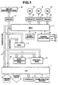
- FIG. 1 is a block diagram illustrating the configuration of a control system of the ink-jet recording apparatus of the embodiment.
- a programmable peripheral interface (hereinafter abbreviated as a "PPI") 1 performs parallel reception of an instruction signal (a command) and a recording-information signal transmitted from a host computer, and transfers the received signals to an MPU (microprocessing unit) 2.
- the PPI 1 also controls a console 6, and performs input processing for a carriage-home-position sensor 7.
- a carriage motor 8 moves a carriage.
- a sheet feeding motor 10 conveys a recording material in a direction perpendicular to the moving direction of the carriage.
- a capping motor 13 drives a capping member (cap, not shown) so as to contact ink discharging ports (not shown) of a recording head 12 (to be described later) and thereby to block the ink discharging ports from the external atmosphere.
- a driver 15 drives the carriage motor 8.
- a driver 16 drives the sheet feeding motor 10.
- a driver 14 drives the capping motor 13.
- the motors 8, 10 and 13 are controlled by the MPU 2, which always keeps track of the state of the motors 8, 10 and 13. For example, the MPU 2 keeps track of whether the cap is opened or closed by controlling the operation of the capping motor 13.
- the home-position sensor 7 is provided in the vicinity of the home position of the carriage in order to detect arrival of the carriage (upon which the recording head 12 is mounted) at the home position.
- a sheet sensor 9 detects whether or not a recording material, such as recording paper or the like, is present, i.e., whether or not the recording material is supplied to a recording portion.
- the recording head 12 is a bubble-jet-type ink-jet recording head, which includes discharging ports (not shown), heaters for discharge (not shown) and the like.
- a driver 11 drives the heaters for discharge of the recording head 12 in accordance with recording data stored in the printing buffer storage of the RAM 3.
- a power supply unit 24 supplies the above-described respective units with electric power, and preferably includes an AC adapter and a rechargeable battery as power supplies for driving the units.
- the MPU 2 is connected to a host apparatus, such as a computer or the like, via the PPI 1, and controls a recording operation based on commands and recording-information signals transmitted from the host apparatus, processing procedures of a program stored in the control ROM 5, and recording data stored in the RAM 3.
- a host apparatus such as a computer or the like
- an AC adapter 19 and a rechargeable battery 20 serve as power supplies for driving the ink-jet recording apparatus.
- a source switcher 21 selects one of the above-described two power supplies, and preferably comprises a DC jack.
- a contact 21a is opened, so that electric power is supplied from the AC adapter 19.
- the contact 21a is closed, so that the negative electrode of the battery 20 is connected to the ground GND and electric power from the battery 20 is supplied.
- An input-voltage detection circuit 23 detects the output voltage of the supplied electric power, and transmits an output signal to an input A/D port of the MPU 2.
- a simple input-voltage detection circuit 23, comprising a resistive voltage divider is used to generate a signal representing the detected voltage, which is input to the MPU 2.
- any other appropriate method such as a method using an A/D converter or a method using a comparator, may also be considered.
- the MPU 2 which has received the output signal from the input-voltage detection circuit 23 at the A/D port can determine whether the supplied electric power is arriving from the AC adapter 19 or from the rechargeable battery 20 by recognizing the input voltage. This determination is performed based on the fact that the voltage from the AC adapter 19 is slightly higher than the voltage from the battery 20.
- a power-supply circuit 22 converts the DC output from the power source into a voltage suitable for driving the respective units of the ink-jet recording apparatus under control via an output port O 1 of the MPU 2.
- a logic voltage V CC1 is also supplied to the MPU 2, and is supplied even in a power-off mode.
- a logic voltage V CC2 and a head voltage V H are supplied to logic units other than the MPU 2, such as the RAM 3 and the like, and to the recording head 12, respectively, and are supplied only in a power-on mode (i.e., a state of recording or awaiting recording).
- the motor voltage V pp is supplied to the motors 8, 10 and 13 (shown in FIG. 1).
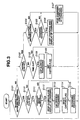
- FIG. 3 is a flowchart illustrating charging procedures by the MPU 2 of the recording apparatus of the embodiment.
- step S101 when the recording apparatus is started, it is determined in step S101 if a recording command from the host apparatus is present. If the result of the determination is negative, the process proceeds to step S102, where it is determined if the recording head is capped. This determination is performed by checking the capping flag (which is turned on/off by the MPU 2 because the MPU 2 controls the capping motor 13 as described above). If the result of the determination in step S102 is negative, i.e,, when the cap is opened, the process proceeds to step S103. If the result of the determination in step S102 is affirmative, i.e., when the cap is closed, the process proceeds to step S104.
- step S103 it is determined if the time after the request for recording processing has been terminated exceeds a predetermined value, i.e., if a time-out has occurred. If the result of the determination in step S103 is negative, the process returns to step S101. If the result of the determination in step S103 is affirmative, the process proceeds to step S108, where the MPU 2 performs processing of closing the cap. Then, in step S109, a capping flag is set.
- automatic capping processing which is well-known processing for preventing the recording head from being clogged when a recording operation is not performed.
- step S101 determines if the recording head is capped based on the capping flag. If the result of the determination in step S110 is negative, i.e., if the cap is opened, the process proceeds to step S115. If the result of the determination in step S110 is affirmative, the process proceeds to step S111, where it is determined if charging is being performed. If the result of the determination in step S111 is affirmative, the process proceeds to step S112, where charging and display of charging are stopped. If the result of the determination in step S111 is negative, the process proceeds to step S113, where cap opening processing is performed.
- step S115 recording processing is performed in accordance with a recording command from the host apparatus.
- the process returns to step S101. If a time-out occurs while waiting for the next recording command from the host apparatus, the cap is closed, and charging processing is resumed if necessary, as described above in connection with steps S102 - S109.
- step S101 of the flowchart shown in FIG. 3 the recording command may be replaced by a self testing recording command.
- the flowchart is, of course, also effective for a case in which the recording command in step S101 is replaced by a request for processing in which it is necessary to temporarily open the cap, such as a command for cleaning the recording head, a command for exchanging an ink cartridge, a command for initializing the apparatus, a command for turning off electric power supply to the apparatus, or the like, and the process of step S111 is replaced by a process corresponding to the concerned command.
- charging skipping control can be assuredly realized by determining whether or not the cap is closed. Hence, the burden on software is small. Furthermore, since whether or not the recording head is present at a retracted position is determined based on whether or not the cap is closed, it is unnecessary to provide a dedicated sensor, and therefore the cost is not increased.
- the home-position sensor 7 (shown in FIG. 1) may, for example, be used as such a sensor.
- the present invention may, of course, be applied to a recording apparatus other than the ink-jet recording apparatus by using the retracted-position sensor.
- the present invention is particularly suitable for use in an ink-jet recording head and in a recording apparatus wherein thermal energy generated by an electrothermal transducer, a laser beam or the like is used to cause a change of state of ink that ejects or discharges the ink. This is because with these devices, a high density of picture elements and a high resolution of recording are possible.
- the principle is such that at least one driving signal is applied to an electrothermal transducer disposed on a liquid (ink) retaining sheet or liquid passage, the driving signal being sufficient to provide a quick temperature rise beyond a nucleate boiling point, by which the thermal energy is provided by the electrothermal transducer to produce film boiling on the heating portion of the recording head, whereby a bubble can be formed in the liquid (ink) corresponding to each driving signal, By the production, development and contraction of the bubble, the liquid (ink) is ejected through an ejection outlet to produce at least one droplet.
- the driving signal is preferably in the form of a pulse, because the development and contraction of the bubble can then be effected instantaneously, and therefore, the liquid (ink) can be ejected with quick response.
- the driving signal in the form of the pulse is preferably such as disclosed in U.S. Patents Nos. 4,463,359 and 4,345,262.
- the temperature increasing rate of the heating surface is preferably such as disclosed in U.S. Patent No. 4,313,124.
- the structure of the recording head may be as shown in U.S. Patents Nos. 4,558,333 and 4,459,600 wherein the heating portion is disposed at a bent portion, as well as the structure of the combination of the ejection outlet, liquid passage and the electrothermal transducer as disclosed in the above-mentioned patents.
- the present invention is applicable to the structure disclosed in Japanese Laid-Open Patent Application No. 123670/1984 wherein a common slit is used as the ejection outlet for a plurality of electrothermal transducers, and to the structure disclosed in Japanese Laid-Open Patent Application No. 138461/1984 wherein an opening for absorbing pressure waves of the thermal energy is formed corresponding to the ejection portion. This is because the present invention is effective to perform the recording operation with certainty and at high efficiency regardless of the type of recording head.
- the present invention is applicable to a serial type recording head wherein the recording head is fixed on the main assembly, to a replaceable chip type recording head which is connected electrically to the main apparatus and which can be supplied with ink when it is mounted in the main assembly, or to a cartridge type recording head having an integral ink container.
- the provisions of the recovery means and/or the auxiliary means for the preliminary operation are preferable, because they can further stabilize the effects of the present invention.
- Examples of such means include capping means for the recording head, cleaning means therefor, pressing or suction means, and preliminary heating means which may be the electrothermal transducer, an additional heating element or a combination thereof.
- means for effecting preliminary ejection (not for the recording operation) can stabilize the recording operation.
- Variations of the recording head mounting may include a single head corresponding to a single color ink, or a plurality of heads corresponding to a plurality of ink materials having different recording colors or densities.
- the present invention may also be effectively applied to an apparatus having at least one of a monochromatic mode mainly with black, a multicolor mode with different color ink materials, a full-color mode using the mixture of colors, which may be an integrally formed recording unit or a combination of a plurality of recording heads.
- an ink material which is solid below room temperature but liquid at room temperature may also be used. Since the ink in this type of recording apparatus is preferably kept within a temperature range between 30 °C and 70 °C, in order to stabilize the viscosity of the ink to provide stabilized ejection, the ink may be such that it is liquid within the temperature range when the recording signal in the present invention is applied. With one type of ink, the temperature rise due to the thermal energy is positively prevented by consuming it for the state change of the ink from the solid state to the liquid state. Another type of ink material is solidified when it is left, to prevent the evaporation of the ink.
- the ink in response to the application of the recording signal producing thermal energy, the ink is liquefied, and the liquefied ink may be ejected.
- Another ink material may start to be solidified at the time when it reaches the recording material.
- the present invention is also applicable to such an ink material as is liquefied by the application of thermal energy.
- Such an ink material may be retained as a liquid or solid material in through holes or recesses formed in a porous sheet as disclosed in Japanese Laid-Open Patent Application Nos. 56847/1979 and 71260/1985.
- the sheet is faced to the electrothermal transducers.
- the most effective one of the techniques described above is the film boiling system.
- the ink-jet recording apparatus may be used as an output terminal of an information processing apparatus such as a computer or the like, as a copying apparatus combined with an image reader or the like, or as a facsimile machine having information sending and receiving functions.
- an information processing apparatus such as a computer or the like
- a copying apparatus combined with an image reader or the like or as a facsimile machine having information sending and receiving functions.
Landscapes
- Accessory Devices And Overall Control Thereof (AREA)
- Ink Jet (AREA)
- Charge And Discharge Circuits For Batteries Or The Like (AREA)
- Printers Characterized By Their Purpose (AREA)
Applications Claiming Priority (3)
| Application Number | Priority Date | Filing Date | Title |
|---|---|---|---|
| JP9313449A JPH11138951A (ja) | 1997-11-14 | 1997-11-14 | 充電機能を有する記録装置及びその充電方法 |
| JP31344997 | 1997-11-14 | ||
| JP313449/97 | 1997-11-14 |
Publications (3)
| Publication Number | Publication Date |
|---|---|
| EP0916511A2 EP0916511A2 (en) | 1999-05-19 |
| EP0916511A3 EP0916511A3 (en) | 2000-04-19 |
| EP0916511B1 true EP0916511B1 (en) | 2003-05-02 |
Family
ID=18041444
Family Applications (1)
| Application Number | Title | Priority Date | Filing Date |
|---|---|---|---|
| EP98309337A Expired - Lifetime EP0916511B1 (en) | 1997-11-14 | 1998-11-13 | Recording apparatus having a charging function, and charging method |
Country Status (5)
| Country | Link |
|---|---|
| US (1) | US6412900B2 (zh) |
| EP (1) | EP0916511B1 (zh) |
| JP (1) | JPH11138951A (zh) |
| CN (1) | CN1085968C (zh) |
| DE (1) | DE69813998T2 (zh) |
Families Citing this family (13)
| Publication number | Priority date | Publication date | Assignee | Title |
|---|---|---|---|---|
| JP4531949B2 (ja) * | 2000-08-21 | 2010-08-25 | オリンパス株式会社 | 携帯用プリンタ装置 |
| JP3870030B2 (ja) * | 2001-02-28 | 2007-01-17 | キヤノン株式会社 | 割込み制御回路を有するインクジェット記録装置および記録装置の制御方法 |
| KR100385063B1 (ko) * | 2001-09-26 | 2003-05-23 | 삼성전자주식회사 | 프린팅기기 및 구동방법 |
| JP4208586B2 (ja) | 2003-01-24 | 2009-01-14 | キヤノン株式会社 | 充電装置及びその充電制御方法 |
| JP3990990B2 (ja) | 2003-01-24 | 2007-10-17 | キヤノン株式会社 | 充電装置、電子機器、充電装置における電池残量表示制御方法、電子機器における電池残量検出方法 |
| US7540581B2 (en) * | 2005-01-06 | 2009-06-02 | Seiko Epson Corporation | Print control method |
| JP2007136257A (ja) * | 2005-11-14 | 2007-06-07 | Seiko Epson Corp | 液滴吐出装置 |
| US8198757B2 (en) * | 2009-03-04 | 2012-06-12 | International Business Machines Corporation | Energy savings for a system powering a lower voltage device from a higher voltage power source, and wherein the system includes a power plug that outputs power to a converter, and a switch actuator |
| JP4997299B2 (ja) * | 2010-02-18 | 2012-08-08 | 東芝テック株式会社 | 印字装置、印字方法、および印字プログラム |
| US9424579B2 (en) * | 2011-03-22 | 2016-08-23 | Fmr Llc | System for group supervision |
| US20140075356A1 (en) * | 2012-09-07 | 2014-03-13 | Service Solutions U.S. Llc | Diagnostic Hub |
| CN106166897B (zh) * | 2016-08-19 | 2018-04-03 | 杭州旗捷科技有限公司 | 充放电电路、墨盒芯片 |
| US10987942B2 (en) * | 2018-02-01 | 2021-04-27 | Fujitsu Component Limited | Printing apparatus |
Family Cites Families (23)
| Publication number | Priority date | Publication date | Assignee | Title |
|---|---|---|---|---|
| CA1127227A (en) | 1977-10-03 | 1982-07-06 | Ichiro Endo | Liquid jet recording process and apparatus therefor |
| JPS5936879B2 (ja) | 1977-10-14 | 1984-09-06 | キヤノン株式会社 | 熱転写記録用媒体 |
| US4330787A (en) | 1978-10-31 | 1982-05-18 | Canon Kabushiki Kaisha | Liquid jet recording device |
| US4345262A (en) | 1979-02-19 | 1982-08-17 | Canon Kabushiki Kaisha | Ink jet recording method |
| US4463359A (en) | 1979-04-02 | 1984-07-31 | Canon Kabushiki Kaisha | Droplet generating method and apparatus thereof |
| US4313124A (en) | 1979-05-18 | 1982-01-26 | Canon Kabushiki Kaisha | Liquid jet recording process and liquid jet recording head |
| US4558333A (en) | 1981-07-09 | 1985-12-10 | Canon Kabushiki Kaisha | Liquid jet recording head |
| JPS59123670A (ja) | 1982-12-28 | 1984-07-17 | Canon Inc | インクジエツトヘツド |
| JPS59138461A (ja) | 1983-01-28 | 1984-08-08 | Canon Inc | 液体噴射記録装置 |
| JPS6071260A (ja) | 1983-09-28 | 1985-04-23 | Erumu:Kk | 記録装置 |
| JPS612864A (ja) | 1984-06-18 | 1986-01-08 | テルモ株式会社 | 医療用具 |
| FR2637844B1 (fr) * | 1988-10-18 | 1990-11-23 | Imaje Sa | Procede d'impression haute resolution au moyen de gouttes d'encre satellites mis en oeuvre dans une imprimante a jet d'encre continu |
| FR2653063B1 (fr) * | 1989-10-16 | 1995-10-27 | Imaje | Tete d'impression a jet d'encre et procede de mise en óoeuvre de cette tete destinee notamment a l'impression de caracteres de grandes dimensions. |
| US5182583A (en) * | 1990-07-17 | 1993-01-26 | Canon Kabushiki Kaisha | Ink-jet having battery capacity detection |
| EP0470545B1 (en) * | 1990-08-06 | 1998-06-03 | Canon Kabushiki Kaisha | Apparatus comprising a power source circuit including a charge circuit |
| FR2678549B1 (fr) * | 1991-07-05 | 1993-09-17 | Imaje | Procede et dispositif d'impression haute-resolution dans une imprimante a jet d'encre continu. |
| IL103705A (en) * | 1991-11-15 | 1995-12-08 | Kuehnle Manfred R | Electro-thermal printing ink and method and printing device with its help |
| JP3337709B2 (ja) | 1992-03-31 | 2002-10-21 | キヤノン株式会社 | 充電制御装置及び該装置の制御方法、電子機器及び電子機器の制御方法 |
| KR940007557A (ko) | 1992-09-07 | 1994-04-27 | 에프. 제이. 스미트 | 전자기 방사주파수를 상승시키는 광학소자 및 광전자 장치 |
| JP3118119B2 (ja) * | 1992-09-08 | 2000-12-18 | キヤノン株式会社 | プリント装置及び該装置における電池の充電方法 |
| DE69421486T2 (de) | 1993-08-27 | 2000-02-10 | Hewlett-Packard Co., Palo Alto | Elektronische Verbindung für Tintenstrahldruckkopf |
| JP3352312B2 (ja) | 1995-02-06 | 2002-12-03 | キヤノン株式会社 | 画像形成システム |
| JPH10217578A (ja) | 1997-02-06 | 1998-08-18 | Canon Inc | プリンタ付情報処理装置 |
-
1997
- 1997-11-14 JP JP9313449A patent/JPH11138951A/ja not_active Withdrawn
-
1998
- 1998-11-12 US US09/190,093 patent/US6412900B2/en not_active Expired - Lifetime
- 1998-11-13 CN CN98124235A patent/CN1085968C/zh not_active Expired - Fee Related
- 1998-11-13 DE DE69813998T patent/DE69813998T2/de not_active Expired - Lifetime
- 1998-11-13 EP EP98309337A patent/EP0916511B1/en not_active Expired - Lifetime
Also Published As
| Publication number | Publication date |
|---|---|
| CN1220209A (zh) | 1999-06-23 |
| DE69813998T2 (de) | 2004-05-19 |
| US6412900B2 (en) | 2002-07-02 |
| JPH11138951A (ja) | 1999-05-25 |
| CN1085968C (zh) | 2002-06-05 |
| EP0916511A2 (en) | 1999-05-19 |
| US20020001007A1 (en) | 2002-01-03 |
| DE69813998D1 (de) | 2003-06-05 |
| EP0916511A3 (en) | 2000-04-19 |
Similar Documents
| Publication | Publication Date | Title |
|---|---|---|
| US5182583A (en) | Ink-jet having battery capacity detection | |
| EP0587385B1 (en) | Printing apparatus and method of charging battery there in | |
| EP0916511B1 (en) | Recording apparatus having a charging function, and charging method | |
| US5673070A (en) | Recording apparatus for controlling recording in accordance with battery capacity | |
| JPH09156128A (ja) | インクジェットプリンタ | |
| US7052105B2 (en) | Battery residual capacity detection method and printing apparatus using the method | |
| EP0564417B1 (en) | Electronic apparatus comprising a charge control means | |
| US6045274A (en) | Power supply apparatus | |
| JP2009113207A (ja) | 電池残量検出方法 | |
| US6782481B2 (en) | Method and apparatus for supplying battery power to a timer circuit within a printer while the printer is powered off | |
| JP2004237450A (ja) | インクジェット記録装置、および該装置の制御方法 | |
| JP3066905B2 (ja) | 記録装置 | |
| JP2714233B2 (ja) | 記録装置 | |
| JP2004230812A (ja) | 電池残量検出方法 | |
| TW412894B (en) | Recording apparatus having a charging function, and charging method | |
| JP2023129917A (ja) | 電源制御ic、及び電源制御システム | |
| JP2004009539A (ja) | 画像記録装置およびその制御方法 | |
| JP2008107164A (ja) | バッテリ残量検出装置およびバッテリ残量検出装置の制御方法 | |
| JP2004233263A (ja) | 電池残量検出方法 | |
| JP2002335639A (ja) | 電子機器 | |
| JPH09104114A (ja) | 記録装置 |
Legal Events
| Date | Code | Title | Description |
|---|---|---|---|
| PUAI | Public reference made under article 153(3) epc to a published international application that has entered the european phase |
Free format text: ORIGINAL CODE: 0009012 |
|
| AK | Designated contracting states |
Kind code of ref document: A2 Designated state(s): DE ES FR GB IT NL |
|
| AX | Request for extension of the european patent |
Free format text: AL;LT;LV;MK;RO;SI |
|
| PUAL | Search report despatched |
Free format text: ORIGINAL CODE: 0009013 |
|
| AK | Designated contracting states |
Kind code of ref document: A3 Designated state(s): AT BE CH CY DE DK ES FI FR GB GR IE IT LI LU MC NL PT SE |
|
| AX | Request for extension of the european patent |
Free format text: AL;LT;LV;MK;RO;SI |
|
| 17P | Request for examination filed |
Effective date: 20000915 |
|
| AKX | Designation fees paid |
Free format text: DE ES FR GB IT NL |
|
| 17Q | First examination report despatched |
Effective date: 20010608 |
|
| GRAG | Despatch of communication of intention to grant |
Free format text: ORIGINAL CODE: EPIDOS AGRA |
|
| GRAG | Despatch of communication of intention to grant |
Free format text: ORIGINAL CODE: EPIDOS AGRA |
|
| GRAH | Despatch of communication of intention to grant a patent |
Free format text: ORIGINAL CODE: EPIDOS IGRA |
|
| GRAH | Despatch of communication of intention to grant a patent |
Free format text: ORIGINAL CODE: EPIDOS IGRA |
|
| GRAA | (expected) grant |
Free format text: ORIGINAL CODE: 0009210 |
|
| AK | Designated contracting states |
Designated state(s): DE ES FR GB IT NL |
|
| PG25 | Lapsed in a contracting state [announced via postgrant information from national office to epo] |
Ref country code: NL Free format text: LAPSE BECAUSE OF FAILURE TO SUBMIT A TRANSLATION OF THE DESCRIPTION OR TO PAY THE FEE WITHIN THE PRESCRIBED TIME-LIMIT Effective date: 20030502 |
|
| REG | Reference to a national code |
Ref country code: GB Ref legal event code: FG4D |
|
| REF | Corresponds to: |
Ref document number: 69813998 Country of ref document: DE Date of ref document: 20030605 Kind code of ref document: P |
|
| PG25 | Lapsed in a contracting state [announced via postgrant information from national office to epo] |
Ref country code: ES Free format text: LAPSE BECAUSE OF FAILURE TO SUBMIT A TRANSLATION OF THE DESCRIPTION OR TO PAY THE FEE WITHIN THE PRESCRIBED TIME-LIMIT Effective date: 20030813 |
|
| NLV1 | Nl: lapsed or annulled due to failure to fulfill the requirements of art. 29p and 29m of the patents act | ||
| ET | Fr: translation filed | ||
| PLBE | No opposition filed within time limit |
Free format text: ORIGINAL CODE: 0009261 |
|
| STAA | Information on the status of an ep patent application or granted ep patent |
Free format text: STATUS: NO OPPOSITION FILED WITHIN TIME LIMIT |
|
| 26N | No opposition filed |
Effective date: 20040203 |
|
| PGFP | Annual fee paid to national office [announced via postgrant information from national office to epo] |
Ref country code: FR Payment date: 20061124 Year of fee payment: 9 |
|
| PGFP | Annual fee paid to national office [announced via postgrant information from national office to epo] |
Ref country code: IT Payment date: 20061130 Year of fee payment: 9 |
|
| REG | Reference to a national code |
Ref country code: FR Ref legal event code: ST Effective date: 20080930 |
|
| PG25 | Lapsed in a contracting state [announced via postgrant information from national office to epo] |
Ref country code: FR Free format text: LAPSE BECAUSE OF NON-PAYMENT OF DUE FEES Effective date: 20071130 |
|
| PG25 | Lapsed in a contracting state [announced via postgrant information from national office to epo] |
Ref country code: IT Free format text: LAPSE BECAUSE OF NON-PAYMENT OF DUE FEES Effective date: 20071113 |
|
| PGFP | Annual fee paid to national office [announced via postgrant information from national office to epo] |
Ref country code: GB Payment date: 20151125 Year of fee payment: 18 Ref country code: DE Payment date: 20151130 Year of fee payment: 18 |
|
| REG | Reference to a national code |
Ref country code: DE Ref legal event code: R119 Ref document number: 69813998 Country of ref document: DE |
|
| GBPC | Gb: european patent ceased through non-payment of renewal fee |
Effective date: 20161113 |
|
| PG25 | Lapsed in a contracting state [announced via postgrant information from national office to epo] |
Ref country code: GB Free format text: LAPSE BECAUSE OF NON-PAYMENT OF DUE FEES Effective date: 20161113 Ref country code: DE Free format text: LAPSE BECAUSE OF NON-PAYMENT OF DUE FEES Effective date: 20170601 |