EP0916359B1 - Dispositif de canule amélioré - Google Patents
Dispositif de canule amélioré Download PDFInfo
- Publication number
- EP0916359B1 EP0916359B1 EP98121448A EP98121448A EP0916359B1 EP 0916359 B1 EP0916359 B1 EP 0916359B1 EP 98121448 A EP98121448 A EP 98121448A EP 98121448 A EP98121448 A EP 98121448A EP 0916359 B1 EP0916359 B1 EP 0916359B1
- Authority
- EP
- European Patent Office
- Prior art keywords
- cannula
- tip
- distal end
- component
- orifices
- Prior art date
- Legal status (The legal status is an assumption and is not a legal conclusion. Google has not performed a legal analysis and makes no representation as to the accuracy of the status listed.)
- Expired - Lifetime
Links
Images
Classifications
-
- A—HUMAN NECESSITIES
- A61—MEDICAL OR VETERINARY SCIENCE; HYGIENE
- A61M—DEVICES FOR INTRODUCING MEDIA INTO, OR ONTO, THE BODY; DEVICES FOR TRANSDUCING BODY MEDIA OR FOR TAKING MEDIA FROM THE BODY; DEVICES FOR PRODUCING OR ENDING SLEEP OR STUPOR
- A61M25/00—Catheters; Hollow probes
- A61M25/0067—Catheters; Hollow probes characterised by the distal end, e.g. tips
- A61M25/0068—Static characteristics of the catheter tip, e.g. shape, atraumatic tip, curved tip or tip structure
-
- A—HUMAN NECESSITIES
- A61—MEDICAL OR VETERINARY SCIENCE; HYGIENE
- A61M—DEVICES FOR INTRODUCING MEDIA INTO, OR ONTO, THE BODY; DEVICES FOR TRANSDUCING BODY MEDIA OR FOR TAKING MEDIA FROM THE BODY; DEVICES FOR PRODUCING OR ENDING SLEEP OR STUPOR
- A61M1/00—Suction or pumping devices for medical purposes; Devices for carrying-off, for treatment of, or for carrying-over, body-liquids; Drainage systems
- A61M1/36—Other treatment of blood in a by-pass of the natural circulatory system, e.g. temperature adaptation, irradiation ; Extra-corporeal blood circuits
- A61M1/3621—Extra-corporeal blood circuits
- A61M1/3653—Interfaces between patient blood circulation and extra-corporal blood circuit
- A61M1/3659—Cannulae pertaining to extracorporeal circulation
-
- A—HUMAN NECESSITIES
- A61—MEDICAL OR VETERINARY SCIENCE; HYGIENE
- A61M—DEVICES FOR INTRODUCING MEDIA INTO, OR ONTO, THE BODY; DEVICES FOR TRANSDUCING BODY MEDIA OR FOR TAKING MEDIA FROM THE BODY; DEVICES FOR PRODUCING OR ENDING SLEEP OR STUPOR
- A61M25/00—Catheters; Hollow probes
- A61M25/0043—Catheters; Hollow probes characterised by structural features
- A61M25/005—Catheters; Hollow probes characterised by structural features with embedded materials for reinforcement, e.g. wires, coils, braids
- A61M25/0053—Catheters; Hollow probes characterised by structural features with embedded materials for reinforcement, e.g. wires, coils, braids having a variable stiffness along the longitudinal axis, e.g. by varying the pitch of the coil or braid
-
- A—HUMAN NECESSITIES
- A61—MEDICAL OR VETERINARY SCIENCE; HYGIENE
- A61M—DEVICES FOR INTRODUCING MEDIA INTO, OR ONTO, THE BODY; DEVICES FOR TRANSDUCING BODY MEDIA OR FOR TAKING MEDIA FROM THE BODY; DEVICES FOR PRODUCING OR ENDING SLEEP OR STUPOR
- A61M25/00—Catheters; Hollow probes
- A61M25/0043—Catheters; Hollow probes characterised by structural features
- A61M25/0054—Catheters; Hollow probes characterised by structural features with regions for increasing flexibility
-
- A—HUMAN NECESSITIES
- A61—MEDICAL OR VETERINARY SCIENCE; HYGIENE
- A61M—DEVICES FOR INTRODUCING MEDIA INTO, OR ONTO, THE BODY; DEVICES FOR TRANSDUCING BODY MEDIA OR FOR TAKING MEDIA FROM THE BODY; DEVICES FOR PRODUCING OR ENDING SLEEP OR STUPOR
- A61M25/00—Catheters; Hollow probes
- A61M25/0067—Catheters; Hollow probes characterised by the distal end, e.g. tips
- A61M25/008—Strength or flexibility characteristics of the catheter tip
-
- A—HUMAN NECESSITIES
- A61—MEDICAL OR VETERINARY SCIENCE; HYGIENE
- A61M—DEVICES FOR INTRODUCING MEDIA INTO, OR ONTO, THE BODY; DEVICES FOR TRANSDUCING BODY MEDIA OR FOR TAKING MEDIA FROM THE BODY; DEVICES FOR PRODUCING OR ENDING SLEEP OR STUPOR
- A61M60/00—Blood pumps; Devices for mechanical circulatory actuation; Balloon pumps for circulatory assistance
- A61M60/10—Location thereof with respect to the patient's body
- A61M60/122—Implantable pumps or pumping devices, i.e. the blood being pumped inside the patient's body
- A61M60/126—Implantable pumps or pumping devices, i.e. the blood being pumped inside the patient's body implantable via, into, inside, in line, branching on, or around a blood vessel
- A61M60/13—Implantable pumps or pumping devices, i.e. the blood being pumped inside the patient's body implantable via, into, inside, in line, branching on, or around a blood vessel by means of a catheter allowing explantation, e.g. catheter pumps temporarily introduced via the vascular system
-
- A—HUMAN NECESSITIES
- A61—MEDICAL OR VETERINARY SCIENCE; HYGIENE
- A61M—DEVICES FOR INTRODUCING MEDIA INTO, OR ONTO, THE BODY; DEVICES FOR TRANSDUCING BODY MEDIA OR FOR TAKING MEDIA FROM THE BODY; DEVICES FOR PRODUCING OR ENDING SLEEP OR STUPOR
- A61M60/00—Blood pumps; Devices for mechanical circulatory actuation; Balloon pumps for circulatory assistance
- A61M60/20—Type thereof
- A61M60/205—Non-positive displacement blood pumps
- A61M60/216—Non-positive displacement blood pumps including a rotating member acting on the blood, e.g. impeller
-
- A—HUMAN NECESSITIES
- A61—MEDICAL OR VETERINARY SCIENCE; HYGIENE
- A61M—DEVICES FOR INTRODUCING MEDIA INTO, OR ONTO, THE BODY; DEVICES FOR TRANSDUCING BODY MEDIA OR FOR TAKING MEDIA FROM THE BODY; DEVICES FOR PRODUCING OR ENDING SLEEP OR STUPOR
- A61M60/00—Blood pumps; Devices for mechanical circulatory actuation; Balloon pumps for circulatory assistance
- A61M60/80—Constructional details other than related to driving
- A61M60/855—Constructional details other than related to driving of implantable pumps or pumping devices
- A61M60/857—Implantable blood tubes
-
- A—HUMAN NECESSITIES
- A61—MEDICAL OR VETERINARY SCIENCE; HYGIENE
- A61M—DEVICES FOR INTRODUCING MEDIA INTO, OR ONTO, THE BODY; DEVICES FOR TRANSDUCING BODY MEDIA OR FOR TAKING MEDIA FROM THE BODY; DEVICES FOR PRODUCING OR ENDING SLEEP OR STUPOR
- A61M60/00—Blood pumps; Devices for mechanical circulatory actuation; Balloon pumps for circulatory assistance
- A61M60/80—Constructional details other than related to driving
- A61M60/855—Constructional details other than related to driving of implantable pumps or pumping devices
- A61M60/865—Devices for guiding or inserting pumps or pumping devices into the patient's body
-
- A—HUMAN NECESSITIES
- A61—MEDICAL OR VETERINARY SCIENCE; HYGIENE
- A61B—DIAGNOSIS; SURGERY; IDENTIFICATION
- A61B17/00—Surgical instruments, devices or methods
- A61B17/34—Trocars; Puncturing needles
- A61B17/3417—Details of tips or shafts, e.g. grooves, expandable, bendable; Multiple coaxial sliding cannulas, e.g. for dilating
-
- A—HUMAN NECESSITIES
- A61—MEDICAL OR VETERINARY SCIENCE; HYGIENE
- A61M—DEVICES FOR INTRODUCING MEDIA INTO, OR ONTO, THE BODY; DEVICES FOR TRANSDUCING BODY MEDIA OR FOR TAKING MEDIA FROM THE BODY; DEVICES FOR PRODUCING OR ENDING SLEEP OR STUPOR
- A61M25/00—Catheters; Hollow probes
- A61M25/0067—Catheters; Hollow probes characterised by the distal end, e.g. tips
- A61M25/0068—Static characteristics of the catheter tip, e.g. shape, atraumatic tip, curved tip or tip structure
- A61M2025/0073—Tip designed for influencing the flow or the flow velocity of the fluid, e.g. inserts for twisted or vortex flow
-
- A—HUMAN NECESSITIES
- A61—MEDICAL OR VETERINARY SCIENCE; HYGIENE
- A61M—DEVICES FOR INTRODUCING MEDIA INTO, OR ONTO, THE BODY; DEVICES FOR TRANSDUCING BODY MEDIA OR FOR TAKING MEDIA FROM THE BODY; DEVICES FOR PRODUCING OR ENDING SLEEP OR STUPOR
- A61M25/00—Catheters; Hollow probes
- A61M25/0067—Catheters; Hollow probes characterised by the distal end, e.g. tips
- A61M25/0068—Static characteristics of the catheter tip, e.g. shape, atraumatic tip, curved tip or tip structure
- A61M25/0069—Tip not integral with tube
-
- A—HUMAN NECESSITIES
- A61—MEDICAL OR VETERINARY SCIENCE; HYGIENE
- A61M—DEVICES FOR INTRODUCING MEDIA INTO, OR ONTO, THE BODY; DEVICES FOR TRANSDUCING BODY MEDIA OR FOR TAKING MEDIA FROM THE BODY; DEVICES FOR PRODUCING OR ENDING SLEEP OR STUPOR
- A61M60/00—Blood pumps; Devices for mechanical circulatory actuation; Balloon pumps for circulatory assistance
- A61M60/10—Location thereof with respect to the patient's body
- A61M60/122—Implantable pumps or pumping devices, i.e. the blood being pumped inside the patient's body
- A61M60/126—Implantable pumps or pumping devices, i.e. the blood being pumped inside the patient's body implantable via, into, inside, in line, branching on, or around a blood vessel
- A61M60/148—Implantable pumps or pumping devices, i.e. the blood being pumped inside the patient's body implantable via, into, inside, in line, branching on, or around a blood vessel in line with a blood vessel using resection or like techniques, e.g. permanent endovascular heart assist devices
Definitions
- the present invention generally relates to cannulas and more particularly pertains to cannulas suited for applications requiring a high degree of maneuverability as well as the ability to accommodate high blood flow rates therethrough with minimal blood damage.
- Cannulas must often be able to satisfy a number of competing requirements.
- the inner diameter of the cannula must be as large as possible in order to accommodate the extremely high flow rates inherent in such application.
- the outer diameter of the cannula should be as small as possible in order to enable it to be maneuvered through the convolutions of the patient's vasculature, for example around the aortic arch through the aortic valve and into the heart.
- a smaller outer diameter minimizes the size of the puncture that must be made in the vasculature in order to gain access thereto.
- the cannula must be stiff enough to allow its distal end to be routed through vasculature by manipulation of its proximal end, yet flexible enough to conform to the vasculature and not injure the tissue it comes into contact with.
- Blind retrograde insertion into for example, the left ventricle through the aortic valve is especially problematic in that an advancing cannula has a natural tendency to enter the sinus region adjacent the valve leaflet and become jammed rather than retrogradely passing through the periodically opened valve.
- substantial flow velocities and possible suction pressures may be involved, the risk of shear or cavitation must be addressed while the presence of a foreign body within the blood flow poses a risk of thrombogenisis especially in flow stagnant areas.
- Cannulas have been previously devised in an attempt to satisfy the requirements associated with heart pump applications but have fallen short of overcoming many of the difficulties involved.
- the importance of preventing the radial collapse of the cannula had been recognized and consequently a spiral spring had previously been incorporated in some cannulas.
- the spiral spring was terminated somewhat short of the distal end and while this does soften the distal end, the section of cannula sans spring was then prone to kinking, and consequently flow obstruction.
- the flexible tip is also subject to being sucked against parts of the vasculature or ventricular apparatus and can subsequently collapse to block the flow of fluid therethrough.
- the wall thickness of hereto known cannulas has been varied along its length. By significantly increasing wall thickness near the proximal end, the necessary forces can be transmitted without sacrificing the flexibility needed at the distal end. However, while this imparts the desired stiffness differentiation, it has the undesired side effect of either significantly increasing the cannula's maximum external diameter or decreasing its minimum internal diameter. Additionally, the entrance ports formed in heretofore known cannulas have failed to take into consideration the substantial blood flow velocities that may be forced therethrough and the injury that may be sustained by the blood due to the abrupt directional changes that are encountered.
- US-A-5,314,418 discloses a draining cannula to be connected with the left atrium, corresponding to the introductory part of claim 1.
- This cannula is connected on its proximal end with an artificial heart forming an extra corporal pump.
- the cannula is placed in the body through the femoral vein until the tip at the distal end of the cannula reaches the septum separating the right atrium from the left atrium.
- the tip is acute to pierce the septum so that the tip will be positioned in the left atrium and the pump pumps blood into the left atrium.
- Such a cannula must have a large longitudinal extension and it should be stiff for transferring the longitudinal pushing force to the tip.
- Proximal of the tip portion there is a curvature portion that is more flexible than a body tubular portion and comprises a thin wire embedded in the wall of the material in a spiral form so as to prevent kinking upon bending.
- US-A-5,061,256 discloses an inflow cannula for intraortic blood pumps.
- This cannula has a spring-loaded body for blind retrograde insertion through the aortic arch, and a soft beveled foldable but resilient tip.
- the pump is an extra vascular blood pump that draws in blood through the orifices of the tip.
- This cannula is formed from a tube which covers a helically formed spring.
- a cannula configuration is needed that is sufficiently soft and sufficiently rounded at the distal end to prevent injury yet not prone to collapse or wall suction. Moreover, the cannula must be sufficiently resistant to deformation to ensure maneuverability without sacrifice to its flow capacity. Blood flow into and through the cannula must be managed so as to minimize damage to the blood while minimizing pressure losses therewithin. Heretofore known cannulas have failed to adequately address these requirements.
- the cannula of the present invention is defined by claim 1.
- the cannula of the present invention overcomes many of the shortcomings of previously known configurations and is especially well suited for but not limited to use in implantable intravascular heart pump applications both as an inflow as well as an outflow conduit. Attached to the distal end of such a device, it enables the assembly to be more easily maneuvered throughout a patient's vasculature and facilitates its blind retrograde insertion past a heart valve while minimizing injury to tissue and leaflets. Once in place, the cannula accommodates maximum blood flow rates with a reduced amount of shear, turbulence and risk of cavitation to thereby minimize blood damage.
- the cannula of the present invention consists of a cylindrical body component of constant diameter and substantially constant wall thickness, wherein its resistance to lateral deflection is nonetheless differentiated along its length. More specifically, the distal end is more flexible than its proximal end, wherein the transition between the different flexibility characteristics may either be gradual or abrupt.
- An abrupt change is achieved by simply joining two materials of disparate flexibility as in a butt joint or a stepped joint.
- a gradual transition is achieved by employing a composite construction wherein the relative content of a relatively more flexible material gradually displaces more and more of a stiffer material as the distal end is approached.
- two materials of differing flexibility are layered and their relative thicknesses are gradually varied while their total thickness is held substantially constant.
- tne cannula is either attached to the pump housing of the associated intravascular pump or is configured to actually serve as the impeller housing. Such alternative configuration not only reduces the number of parts that must be separately assembled but additionally smooths the transition between the pump housing and cannula so as not to disrupt blood flow.
- an additional feature incorporated in the body of the cannula is an embedded spiral spring which imparts resistance to radial deformation.
- the function of the spring may be served by a metallic tube incorporated within the cannula that has an advantageous pattern of voids formed therein.
- the tube serves to simultaneously impart a varying degree of flexibility to the tube while preventing its radial deformation. Similar effect is achievable with various patterns of voids formed in the tube wherein the density of the void pattern at any given position along its length is determinative of the structure's flexibility as such position.
- a rigid tip component Disposed at the distal end of the cannula body is a rigid tip component that includes a number of features that serve to overcome the disadvantages inherent in previously known cannula tips.
- the tip is formed of a substantially non-collapsible material having a number of openings formed therein.
- the openings are formed on all sides of the component and are of sufficient size such that the complete blockage of one such opening, as would occur if the tip becomes positioned against the heart or vessel wall, does not significantly compromise the flow capacity of the cannula.
- the openings are configured so as to minimize the risk of wall suction. This is achieved by elongating the openings along the length of the tip in order to minimize the possibility of even a single opening becoming entirely occluded.
- the elongated openings may additionally be angled relative the central axis to achieve a somewhat helical configuration.
- the distal end of the tip is substantially closed and well rounded.
- An orifice is additionally centrally formed therein to accommodate a guide wire should one be used for the placement of the device.
- the rigid tip is either formed separately and attached to the flexible distal end of the cannula or is formed as part of the cannula wherein the cannula's stiffness is abruptly increased near its distal end.
- the inner wall adjacent the downstream edges of the orifices is shaped so as to manage the flow of blood thereabout.
- flow characteristic out through the tip may be enhanced with the modification of the interior volume so as to define a parabolic cone extending proximally along the central axis.
- the base of the cone joins the walls of the tip component immediately adjacent the distal-most reach of the openings. Additionally, the openings may be extended into the rounded region of the distal end of the tip component.
- a monitoring device such as a pressure sensor may be embedded in the cannula in order to provide information regarding the condition of the patient and/or operation of the blood pump.
- the sensor as well as any electrical conduits necessary for its operation are incorporated in the wall of the device during its fabrication.
- the fabrication of the cannula of the present invention is generally accomplished by assembling the various components about a mandrel such as by successively coating layers of material of differing stiffness thereon. By varying the distribution of successive layers of the selected materials and/or the width of the spiral spring structure, the desired stiffness differentiation is achieved. Other components such as a stiffening component, a spiral spring and sensors are incorporated in the wall of the cannula by their placements between layers of the successively applied material.
- the figures generally illustrate the cannula of the present invention.
- the cannula is most advantageously used as an inflow conduit on the distal end of an implantable intravascular heart pump. In such application it serves to enhance maneuverability through the vasculature and upon placement, accommodates extremely high flow rates with a minimum of adverse effects to the pumped blood.
- the cannula provides similar advantages when used as an outflow conduit.
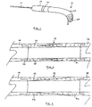
- Fig. 1 is a perspective view showing the cannula 12 attached to the distal end of an implantable intravascular blood pump 14.
- Manipulation of a catheter 16 extending from the proximal end of the pump allows the assembly to be maneuvered through the vasculature to the pumping site such as for example up through the femoral artery, around the aortic arch and with the tip extending into the left ventricle.
- the outer diameter of the cannula must be limited to about 8 mm while its length must be sufficient to ensure that the pump's discharge port 20 is located clear of the aortic valve even while the tip 18 of the cannula is bottomed out in the left ventricle of a large patient (about 8 cm). Similar dimensions are appropriate for right ventricle applications wherein the distally disposed cannula serves as an outflow conduit.
- the cannula device of the present invention very generally consists of a body component 22 of differentiated flexibility and a rigid tip component 24.
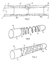
- Fig. 2 is enlarged, longitudinally compressed, cross-sectional view of the body portion 22 of the cannula 12 of the present invention.
- a rigid pump housing 14 is attached at its proximal end while rigid tip 24 is attached thereto at its distal end.
- the components are engaged in a stepped 26 fashion and are permanently bonded to one another.
- the body component has a constant wall thickness along its entire length and is formed as a layered composite of two materials, one relatively stiff 28, the other relatively more flexible 30.
- a similar effect can be achieved with the use of two materials of identical chemical composition, albeit with different physical characteristics, such as a polyurethane with different degrees of polymerization.
- the layers are arranged such that the thickness of one material gradually diminishes as the other increases. In the embodiment illustrated in Fig.
- Fig. 2 illustrates an embodiment wherein an abrupt change in flexibility is achieved by joining two materials of differentiated flexibility 28b, 30b in a stepped fashion at 31. In either case, at the proximal end of the cannula body, its composition comprises substantially 100% of the stiffer material while at the distal end, the composition comprises substantially 100% of the more flexible material.
- the stiffer material may consist of any number of materials including but not limited to a polyurethane or resin impregnated fibers while the more flexible material may consist of any number of materials including but not limited to a silicone compound.
- the two different materials may in fact comprise the same chemical composition yet be differentiated in terms of for example, degree of polymerization or crystallinity. Two forms of a polyurethane for example, may be combined in accordance with the present invention to yield a flexibility differentiated cannula.
- a spiral spring 29 of for instance, NiTi wire Embedded within the wall of the body structure.
- the presence of the spring imparts significant resistance to radial deformation while the particular alloy employed allows the spring to regain its original shape even after a substantial deformation that it may be subjected to during placement or manipulation of the heart.
- the spring wire may have any number of cross-sectional shapes including but not limited to round or rectangular cross-sections with the further option of varying axial density in order to change the elasticity or flexibility of the cannula.
- a metal tube 60 within the cannula's cylindrical wall, wherein such tube has a pattern of voids 62 formed therein such as by laser cutting.
- voids may be patterned to form a helix similar in appearance to the spiral spring described above.
- the pattern of voids cut into the tube may additionally be differentiated along its length such that the tube's resistance to lateral deflection is commensurately varied.
- Fig. 6 illustrates a further alternative of tubular stiffening component 64 wherein a pattern of rectangular voids 66, varied in terms of size of distribution density imparts the desired differentiation in terms of flexibility.
- the proximal end is solid and thus its stiffness in uncompromised to enable it to serve as a pump housing while the distal end 70 is similarly solid to serve as reinforcement of the tip component to provide for maximal rigidity.
- the tube 60, 64 thereby serves to simultaneously provide radial stiffness and a varying degree of resistance to lateral deflection.
- differentiated flexibility is achieved exclusively via the laser cut metal tube while the polymer makeup of the cannula is unvaried along its length.
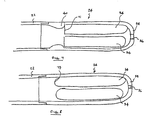
- Figs. 7 and 8 illustrates the rigid tip component 24 of the cannula.
- Such component may be a separate injection molded part or alternatively, may be of integral construction and incorporates a number of features especially advantageous for high inflow rate applications.
- a number of large elongated openings 34 extend along its length, while a central hole 36 at the very distal end is sized to accommodate a guide wire.
- the distal end 38 is smooth and rounded without additional openings to prevent injury upon contacting tissue, and/or valve leaflets.
- the interior surface of the tip component directly adjacent the squared off proximal or inflow end 71 of openings 34 is formed with an edge contour 40 of generally parabolic cross-section that serves to manage the flow of blood thereabout.
- the shape not only presents a rounded surface at the point of initial contact with the incoming blood, but additionally serves to smoothly attach the flow of blood to the interior wall with its asymptotic trailing edge contour.
- the risk of excessive shear and cavitation is minimized to thereby minimize the risk of hemolysis while areas of eddying or of low flow rates are substantially eliminated to thereby mitigate the risk of thrombogenisis.
- Similar advantages may be achieved by rounding the downstream edges 73 of the openings as shown in Fig. 8. Such configuration provides the advantage of being easily molded.
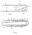
- Fig. 9 illustrates an alternative embodiment especially well suited for outflow applications.
- the distal end of the interior volume of the tip component is fitted with a generally parabolic protuberance 60 extending proximally along the central axis.
- Such element directs flow out through the openings 34a and effectively prevents flow impingement onto a closed distal wall. The resulting reduction in eddying and areas of stagnant flow reduces thrombogenisis.
- the embodiment additionally illustrates a slanted orientation of the openings 34a as well as their extension well into the rounded distal area 61.
- Fig. 10 illustrates an alternative embodiment that incorporates a number of additional features not present in the embodiments shown in the preceding figures.
- the device is of integrated construction such that the rigid proximal end of the cannula forms the pump housing 41 while the flexible distal end seamlessly transitions into the rigid tip component 43. No joints or bonds are formed and thus, the seamless transitions from the tip 43 to the cannula 45 and from the cannula 45 to the pump housing 41 effectively obviate any disruption of bloodflow thereover.
- the desired differentiations in stiffness are achieved by the varied content of epoxy impregnated fibers windings 47 incorporated within the structure. By closely spacing such fibers, and thereby displacing all of a second substantially more flexible material, maximum strength is achieved.
- a layer of biocompatible material 48, 50 coats both the internal as well as external surfaces of the device.
- the thickness of the internal layer is increased 51 under the spiral spring 44 so as to preclude migration of such spring into the blood flow.
- the spring wire shown in Fig. 9 is of rectangular construction to thereby minimize the wall thickness of the device which is constant along its entire length.
- the proximal end of the spring is incorporated well within the fiber windings.
- a sensor 52 is incorporated in the wall of the device. In some applications it is desirable to monitor any of a number of parameters at such location for the purpose of gauging the patient's condition and/or the performance of, for example, the associated pump.
- the fabrication of the device illustrated in Fig. 10 is achieved by first applying a layer 48 of biocompatible polymer such as polyurethane to a highly polished mandrel 54.
- the thickness of the layer is increased 51 slightly near where the spiral spring 44 is to be subsequently positioned in order to prevent migration of the spring into the fluid path.
- Pre-impregnated carbon fiber filaments 47 are then wound about the coated mandrel at an approximate 45° angle to ensure good stability against axial and radial deformation.
- the spacing of successive windings is controlled such that the fiber content is maximized in those areas where maximum stiffness is desired, i.e., the pump housing and tip component. Such spacing is gradually increased in those areas where gradually more flexibility is desired. Areas 55,where maximum flexibility is desired are totally devoid of fibers.
- the outside surface is machined down to its final dimension and the ports are formed in the tip component 43.
- Layers of an elastic polymer 49 such as polyurethane or silicone are then applied in order to fill the areas between adjacent fibers and the spring windings.
- a final layer 50 of biocompatible polymer is applied to the exterior of the entire device to render all surfaces biocompatible. After all materials have cured, the finished device is slipped off the mandrel 54.
- the tip component 24 is fabricated separately such as by injection molding.
- the tip is then either attached by adhesive or by solvent bonding.
- a final layer of biocompatible polymer may then be applied to the assembly to render its surfaces biocompatible and to fill in any gaps that may be present along the joints between adjacent components.
- a single stiffening component comprising the pump housing, cannula and tip are fashioned from a single metal tube having a varying pattern of voids formed therein such as by laser cutting. Since the density of voids at any given point along its length determines the resulting flexibility of the structure at such point, no voids or a minimum of voids are formed in the pump housing and tip sections of the device while a pattern of voids is formed therebetween to impart an increasing degree of flexibility to the cannula's body component. The surfaces of the tube and the voids therebetween are subsequently coated and filled with a polymer in a fashion as described above.
- the cannula of the present invention attached to the distal end of an implantable intravascular blood pump, is inserted into the femoral artery and maneuvered upwardly toward the heart.
- the device may be inserted directly into the aorta via a sternotomy.
- the flexible distal end permits the device to negotiate the convolutions of the artery including the aortic arch.
- the increased stiffness of the proximal end permits adequate axial and torsional forces to be transmitted to the tip to enhance control thereof and thereby facilitate proper advancement of the device.
- Blind retrograde insertion through the aortic valve is accomplished by simply advancing the tip until the valve is engaged.
- the tip attempt to enter while the aortic valve will simply pass into the left ventricle.
- the tip attempt to enter while the aortic valve is closed, it will engage the sinus region behind the leaflet, while further advancement will cause the flexible region near the cannula's distal end to fold over to allow a more proximal and stiffer section of the cannula to breach the valve first.
- the device can be pulled back and reinserted. Once inside, the cannula has room to unfold and is ready for service.
- a similar technique is used for right side placement.
Landscapes
- Health & Medical Sciences (AREA)
- Heart & Thoracic Surgery (AREA)
- Life Sciences & Earth Sciences (AREA)
- Engineering & Computer Science (AREA)
- General Health & Medical Sciences (AREA)
- Public Health (AREA)
- Biomedical Technology (AREA)
- Veterinary Medicine (AREA)
- Hematology (AREA)
- Animal Behavior & Ethology (AREA)
- Anesthesiology (AREA)
- Cardiology (AREA)
- Biophysics (AREA)
- Pulmonology (AREA)
- Mechanical Engineering (AREA)
- Vascular Medicine (AREA)
- External Artificial Organs (AREA)
- Materials For Medical Uses (AREA)
- Media Introduction/Drainage Providing Device (AREA)
- Measurement Of The Respiration, Hearing Ability, Form, And Blood Characteristics Of Living Organisms (AREA)
Claims (15)
- Canule pour guider l'écoulement d'un fluide la traversant et pour faciliter son acheminement à travers le système vasculaire, comprenant :dans laquelleun composant de corps cylindrique (22) dont l'épaisseur de paroi est constante, et présentant un degré graduellement variable de résistance à la déflexion latérale, et dont l'extrémité proximale est plus rigide que l'extrémité distale ;une structure de support (29, 60) disposée à l'intérieur de la paroi dudit composant de corps cylindrique et conférant une résistance à l'écrasement radial ;un composant de pointe creux rigide (24) attaché à l'extrémité distale dudit composant de corps et comprenant une pluralité d'orifices (34) formés dans celui-ci ;une pompe sanguine (14) formant l'extrémité proximale de ladite canule,
ladite pompe sanguine (14) est une pompe sanguine intra-vasculaire comprenant un port de décharge (20) et aspirant du sang à travers les orifices (34) du composant de pointe (24) ;
ledit composant de pointe (24) présente une extrémité distale lisse et arrondie ; et,
la structure de support (29, 60) s'étend à partir de la pompe sanguine (14) jusqu'au composant de pointe (24). - Canule selon la revendication 1, dans laquelle le composant de corps est constitué d'au moins deux matériaux comprenant un premier matériau rigide (28) qui est plus rigide qu'un deuxième matériau flexible (30), et dans laquelle la teneur relative desdits deux matériaux varie le long de la longueur dudit composant de corps.
- Canule selon la revendication 2, dans laquelle lesdits deux matériaux (28, 30) présentent des compositions chimiques identiques mais des duretés durométriques différentes.
- Canule selon la revendication 2, dans laquelle ledit premier matériau comprend des enroulements de fibres (29).
- Canule selon la revendication 4, dans laquelle la densité desdites fibres (29) varie graduellement le long de la longueur de ladite canule.
- Canule selon l'une quelconque des revendications 1 à 5, dans laquelle ladite structure de support (29, 60) comprend un matériau résilient.
- Canule selon l'une quelconque des revendications 1 à 6, dans laquelle lesdits orifices (34) sont allongés et agencés le long de l'axe longitudinal.
- Canule selon la revendication 7, dans laquelle lesdits orifices (34a) sont allongés et sont inclinés par rapport à l'axe longitudinal.
- Canule selon l'une quelconque des revendications 1 à 8, dans laquelle ledit composant de pointe comprend un trou de fil de guidage (36) formé dans celui-ci.
- Canule selon l'une quelconque des revendications 1 à 9, dans laquelle un étranglement parabolique saillant vers l'intérieur (40) est formé au voisinage du bord de fuite de chaque orifice (34).
- Canule selon l'une quelconque des revendications 1 à 10, dans laquelle une saillie parabolique (60) s'étend, d'une façon proximale à l'intérieur de ladite pointe le long de son axe longitudinal, et engage ledit composant de pointe à proximité de l'extrémité distale desdits orifices.
- Canule selon l'une quelconque des revendications 1 à 11, comprenant en outre un capteur incorporé dans ledit composant de corps.
- Canule selon l'une quelconque des revendications 1 à 12, dans laquelle un tube métallique (60) comprend ladite structure de support, et dans laquelle ledit tube métallique comprend des vides (62, 66) formés dans celui-ci, dont la forme et la taille sont variables de manière à conférer ledit degré de résistance variable à une déflexion latérale.
- Canule selon la revendication 13, dans laquelle ledit tube comprend des vides (62) formés dans celui-ci de manière à définir une hélice présentant des pas variables.
- Canule selon la revendication 14, dans laquelle le tube comprend des vides (66) formés dans celui-ci de manière à définir une hélice présentant une largeur variable.
Applications Claiming Priority (2)
| Application Number | Priority Date | Filing Date | Title |
|---|---|---|---|
| US08/970,135 US6007478A (en) | 1997-11-13 | 1997-11-13 | Cannula having constant wall thickness with increasing distal flexibility and method of making |
| US970135 | 1997-11-13 |
Publications (2)
| Publication Number | Publication Date |
|---|---|
| EP0916359A1 EP0916359A1 (fr) | 1999-05-19 |
| EP0916359B1 true EP0916359B1 (fr) | 2004-09-22 |
Family
ID=25516493
Family Applications (1)
| Application Number | Title | Priority Date | Filing Date |
|---|---|---|---|
| EP98121448A Expired - Lifetime EP0916359B1 (fr) | 1997-11-13 | 1998-11-11 | Dispositif de canule amélioré |
Country Status (6)
| Country | Link |
|---|---|
| US (1) | US6007478A (fr) |
| EP (1) | EP0916359B1 (fr) |
| JP (1) | JPH11239617A (fr) |
| AT (1) | ATE276784T1 (fr) |
| CA (1) | CA2254006A1 (fr) |
| DE (1) | DE69826411T2 (fr) |
Cited By (29)
| Publication number | Priority date | Publication date | Assignee | Title |
|---|---|---|---|---|
| US7625353B2 (en) | 2004-05-27 | 2009-12-01 | Abbott Laboratories | Catheter having first and second guidewire tubes and overlapping stiffening members |
| US7628769B2 (en) | 2004-05-27 | 2009-12-08 | Abbott Laboratories | Catheter having overlapping stiffening members |
| US7658723B2 (en) | 2004-05-27 | 2010-02-09 | Abbott Laboratories | Catheter having plurality of stiffening members |
| US7785318B2 (en) | 2004-05-27 | 2010-08-31 | Abbott Laboratories | Catheter having plurality of stiffening members |
| US7785439B2 (en) | 2004-09-29 | 2010-08-31 | Abbott Laboratories Vascular Enterprises Limited | Method for connecting a catheter balloon with a catheter shaft of a balloon catheter |
| US7794448B2 (en) | 2004-05-27 | 2010-09-14 | Abbott Laboratories | Multiple lumen catheter and method of making same |
| US7815627B2 (en) | 2004-05-27 | 2010-10-19 | Abbott Laboratories | Catheter having plurality of stiffening members |
| US8323432B2 (en) | 2002-12-31 | 2012-12-04 | Abbott Laboratories Vascular Enterprises Limited | Catheter and method of manufacturing same |
| US8992163B2 (en) | 2004-09-17 | 2015-03-31 | Thoratec Corporation | Expandable impeller pump |
| US9327068B2 (en) | 1999-09-03 | 2016-05-03 | Maquet Cardiovascular Llc | Guidable intravascular blood pump and related methods |
| US9512839B2 (en) | 2009-05-05 | 2016-12-06 | Ecp Entwicklungsgesellschaft Mbh | Fluid pump changeable in diameter, in particular for medical application |
| US10722631B2 (en) | 2018-02-01 | 2020-07-28 | Shifamed Holdings, Llc | Intravascular blood pumps and methods of use and manufacture |
| US10920596B2 (en) | 2010-07-15 | 2021-02-16 | Ecp Entwicklungsgesellschaft Mbh | Radially compressible and expandable rotor for a pump having an impeller blade |
| US11185677B2 (en) | 2017-06-07 | 2021-11-30 | Shifamed Holdings, Llc | Intravascular fluid movement devices, systems, and methods of use |
| US11511103B2 (en) | 2017-11-13 | 2022-11-29 | Shifamed Holdings, Llc | Intravascular fluid movement devices, systems, and methods of use |
| US11628280B2 (en) | 2012-12-21 | 2023-04-18 | Ecp Entwicklungsgesellschaft Mbh | Sheath assembly for insertion of a cord-shaped element, particularly a catheter, into the body of a patient |
| US11654275B2 (en) | 2019-07-22 | 2023-05-23 | Shifamed Holdings, Llc | Intravascular blood pumps with struts and methods of use and manufacture |
| US11666746B2 (en) | 2011-09-05 | 2023-06-06 | Ecp Entwicklungsgesellschaft Mbh | Medical product comprising a functional element for the invasive use in a patient's body |
| US11724089B2 (en) | 2019-09-25 | 2023-08-15 | Shifamed Holdings, Llc | Intravascular blood pump systems and methods of use and control thereof |
| US11964145B2 (en) | 2019-07-12 | 2024-04-23 | Shifamed Holdings, Llc | Intravascular blood pumps and methods of manufacture and use |
| US12102815B2 (en) | 2019-09-25 | 2024-10-01 | Shifamed Holdings, Llc | Catheter blood pumps and collapsible pump housings |
| US12121713B2 (en) | 2019-09-25 | 2024-10-22 | Shifamed Holdings, Llc | Catheter blood pumps and collapsible blood conduits |
| US12161857B2 (en) | 2018-07-31 | 2024-12-10 | Shifamed Holdings, Llc | Intravascular blood pumps and methods of use |
| US12220570B2 (en) | 2018-10-05 | 2025-02-11 | Shifamed Holdings, Llc | Intravascular blood pumps and methods of use |
| EP4566653A3 (fr) * | 2016-09-01 | 2025-08-13 | Abiomed, Inc. | Entrée de pompe à sang anti-aspiration |
| US12409310B2 (en) | 2019-12-11 | 2025-09-09 | Shifamed Holdings, Llc | Descending aorta and vena cava blood pumps |
| US12465748B2 (en) | 2019-08-07 | 2025-11-11 | Supira Medical, Inc. | Catheter blood pumps and collapsible pump housings |
| EP4582127A4 (fr) * | 2022-09-29 | 2025-11-26 | Terumo Corp | Corps long médical et cathéter à ballonnet |
| US12502524B2 (en) | 2021-12-03 | 2025-12-23 | Kardion Gmbh | Cardiac pump with optical fiber for laser doppler |
Families Citing this family (209)
| Publication number | Priority date | Publication date | Assignee | Title |
|---|---|---|---|---|
| US20030069522A1 (en) * | 1995-12-07 | 2003-04-10 | Jacobsen Stephen J. | Slotted medical device |
| US6889082B2 (en) | 1997-10-09 | 2005-05-03 | Orqis Medical Corporation | Implantable heart assist system and method of applying same |
| US6173199B1 (en) * | 1998-05-05 | 2001-01-09 | Syncro Medical Innovations, Inc. | Method and apparatus for intubation of a patient |
| EP1212185A1 (fr) * | 1999-07-23 | 2002-06-12 | TFX Medical Extrusion Products | Dispositif introducteur a flexibilite variable et resistant au vrillage et procede de fabrication |
| WO2001007101A1 (fr) * | 1999-07-23 | 2001-02-01 | Tfx Medical Extrusion Products | Dispositif a catheter dote d'une tige multilumieres renforcee et son procede de fabrication |
| JP4159781B2 (ja) * | 1999-09-03 | 2008-10-01 | エイ−メド システムズ, インコーポレイテッド | ガイド可能血管内血液ポンプおよび関連する方法 |
| JP2001161805A (ja) * | 1999-12-10 | 2001-06-19 | Hideo Takehara | 留置l型カテーテル |
| DE10059714C1 (de) * | 2000-12-01 | 2002-05-08 | Impella Cardiotech Ag | Intravasale Pumpe |
| US6685679B2 (en) * | 2000-12-06 | 2004-02-03 | Scimed Life Systems, Inc. | Interlocking metal shaft |
| US6500130B2 (en) | 2000-12-21 | 2002-12-31 | Scimed Life Systems, Inc. | Steerable guidewire |
| US6585719B2 (en) | 2001-01-04 | 2003-07-01 | Scimed Life Systems, Inc. | Low profile metal/polymer tubes |
| US6719804B2 (en) | 2001-04-02 | 2004-04-13 | Scimed Life Systems, Inc. | Medical stent and related methods |
| US6994666B2 (en) * | 2001-06-05 | 2006-02-07 | Edwards Lifesciences Corporation | Non-porous smooth ventricular assist device conduit |
| US7455666B2 (en) | 2001-07-13 | 2008-11-25 | Board Of Regents, The University Of Texas System | Methods and apparatuses for navigating the subarachnoid space |
| US6620202B2 (en) | 2001-10-16 | 2003-09-16 | Scimed Life Systems, Inc. | Medical stent with variable coil and related methods |
| US20030236506A1 (en) * | 2002-06-20 | 2003-12-25 | Eric Schofield | Dual outside diameter cannula for insertion into bone |
| US7686758B2 (en) * | 2002-09-10 | 2010-03-30 | Hitmac (Usa), Inc. | Cannula tip for a cardiac assist device |
| US6802806B2 (en) | 2002-09-23 | 2004-10-12 | Cleveland Clinic Foundation | Apparatus for use with an inflow cannula of ventricular assist device |
| DE20304533U1 (de) * | 2003-03-21 | 2004-08-05 | Impella Cardiosystems Ag | Einführvorrichtung zum Einführen eines Gegenstandes in ein Körpergefäß |
| DE10336902C5 (de) | 2003-08-08 | 2019-04-25 | Abiomed Europe Gmbh | Intrakardiale Pumpvorrichtung |
| EP1748814A1 (fr) * | 2004-05-27 | 2007-02-07 | Abbott Laboratories | Catheter presentant une partie de corps principale munie d'un passage de fil-guide delimite par une bobine |
| US7824358B2 (en) * | 2004-07-22 | 2010-11-02 | Thoratec Corporation | Heart pump connector |
| WO2006020942A1 (fr) | 2004-08-13 | 2006-02-23 | Delgado Reynolds M Iii | Methode et appareil d'assistance a long terme d'un ventricule gauche dans le pompage de sang |
| EP1850789B1 (fr) * | 2005-02-14 | 2009-12-09 | Vascutek Limited | Vaisseau sanguin artificiel |
| US20060253059A1 (en) * | 2005-04-21 | 2006-11-09 | Edwards Lifesciences, Llc | Soft-flow aortic cannula tip |
| US20060258987A1 (en) * | 2005-05-10 | 2006-11-16 | Cook Incorporated | Catheter stiffening member |
| US20070073310A1 (en) * | 2005-09-29 | 2007-03-29 | Cook Incorporated | Method for joining medical devices |
| US8672611B2 (en) | 2006-01-13 | 2014-03-18 | Heartware, Inc. | Stabilizing drive for contactless rotary blood pump impeller |
| EP1977110B8 (fr) | 2006-01-13 | 2018-12-26 | HeartWare, Inc. | Pompe sanguine rotative |
| US8554336B2 (en) * | 2006-03-23 | 2013-10-08 | Cardiac Pacemakers, Inc. | Medical lead having a variable change in stiffness |
| CN101448535B (zh) | 2006-03-23 | 2011-10-19 | 宾州研究基金会 | 带有可膨胀叶轮泵的心脏辅助装置 |
| US20070233040A1 (en) * | 2006-03-31 | 2007-10-04 | Boston Scientific Scimed, Inc. | Flexible endoscope with variable stiffness shaft |
| US8246574B2 (en) * | 2006-04-21 | 2012-08-21 | Abbott Laboratories | Support catheter |
| US7927305B2 (en) | 2006-04-21 | 2011-04-19 | Abbott Laboratories | Systems, methods, and devices for injecting media contrast |
| US7993303B2 (en) | 2006-04-21 | 2011-08-09 | Abbott Laboratories | Stiffening support catheter and methods for using the same |
| US8206370B2 (en) | 2006-04-21 | 2012-06-26 | Abbott Laboratories | Dual lumen guidewire support catheter |
| US7890174B2 (en) * | 2006-06-02 | 2011-02-15 | Cardiac Pacemakers, Inc. | Medical electrical lead with deployable fixation features |
| US20080058767A1 (en) * | 2006-09-06 | 2008-03-06 | Rotman Carlos A | Tubal cannulator and methods of use |
| EP2476384B1 (fr) | 2006-11-22 | 2015-11-04 | Applied Medical Resources Corporation | Canule de trocart avec embout atraumatique |
| US9028392B2 (en) * | 2006-12-01 | 2015-05-12 | NuCardia, Inc. | Medical device |
| US20080140022A1 (en) * | 2006-12-08 | 2008-06-12 | Warsaw Orthopedic, Inc. | Coated Cannula with Protective Tip for Insertion Into a Patient |
| US8622931B2 (en) * | 2007-02-09 | 2014-01-07 | Boston Scientific Scimed, Inc. | Extruded guidewires and methods of making |
| AT504990B1 (de) | 2007-02-27 | 2008-12-15 | Miracor Medizintechnik Handels | Katheter zur unterstützung der leistung eines herzens |
| JP5441336B2 (ja) * | 2007-05-11 | 2014-03-12 | テルモ株式会社 | ガイドワイヤ |
| US7828710B2 (en) * | 2007-06-05 | 2010-11-09 | Medical Value Partners, Llc | Apparatus comprising a drive cable for a medical device |
| EP2164548A4 (fr) | 2007-06-26 | 2011-12-07 | Avalon Lab Llc | Canule veineuse coaxiale |
| US8079948B2 (en) * | 2007-08-29 | 2011-12-20 | NuCardia, Inc. | Article comprising an impeller |
| EP2195051B1 (fr) * | 2007-09-14 | 2019-11-27 | Nordson Corporation | Bande de renfort de canule et procédé |
| US8489190B2 (en) | 2007-10-08 | 2013-07-16 | Ais Gmbh Aachen Innovative Solutions | Catheter device |
| US8439859B2 (en) | 2007-10-08 | 2013-05-14 | Ais Gmbh Aachen Innovative Solutions | Catheter device |
| US8167809B2 (en) | 2007-12-20 | 2012-05-01 | Silicon Valley Medical Instruments, Inc. | Imaging probe housing with fluid flushing |
| US9095685B2 (en) * | 2008-01-23 | 2015-08-04 | Mediguide Ltd. | Sensor mounted flexible guidewire |
| CA2650705C (fr) * | 2008-01-23 | 2017-07-11 | Mediguide Ltd. | Appareil d'interconnexion de fil-guide |
| JP5331826B2 (ja) | 2008-03-10 | 2013-10-30 | フォルティメディクス・サージカル・ベスローテン・フェンノートシャップ | 内視鏡用途のための器具を作製する方法及びこの方法を用いて得られる内視鏡用途のための器具 |
| EP3269294A1 (fr) | 2008-04-18 | 2018-01-17 | Fortimedix Surgical B.V. | Instrument pour applications endoscopiques ou similaires |
| CN102083481B (zh) * | 2008-07-16 | 2014-09-03 | 哈特威尔公司 | 与心室辅助装置一起使用的套管尖端 |
| CH699338B1 (de) * | 2008-08-06 | 2012-01-13 | Carag Ag | Vorrichtung zur Messung der Durchblutung in einem Körpergewebe. |
| US8535243B2 (en) | 2008-09-10 | 2013-09-17 | Boston Scientific Scimed, Inc. | Medical devices and tapered tubular members for use in medical devices |
| EP3050537A1 (fr) | 2008-10-06 | 2016-08-03 | Indiana University Research and Technology Corporation | Procédés et appareil destinés à une assistance active ou passive dans le système circulatoire |
| EP2194278A1 (fr) | 2008-12-05 | 2010-06-09 | ECP Entwicklungsgesellschaft mbH | Pompe à fluide dotée d'un rotor |
| US8795254B2 (en) | 2008-12-10 | 2014-08-05 | Boston Scientific Scimed, Inc. | Medical devices with a slotted tubular member having improved stress distribution |
| EP2216059A1 (fr) | 2009-02-04 | 2010-08-11 | ECP Entwicklungsgesellschaft mbH | Dispositif de cathéter doté d'un cathéter et d'un dispositif d'actionnement |
| EP2229965A1 (fr) | 2009-03-18 | 2010-09-22 | ECP Entwicklungsgesellschaft mbH | Pompe à fluide dotée d'une forme spéciale de lame de rotor |
| EP2246078A1 (fr) | 2009-04-29 | 2010-11-03 | ECP Entwicklungsgesellschaft mbH | Agencement d'arbres doté d'un arbre se déroulant à l'intérieur d'une enveloppe rempli de fluide |
| EP2266640A1 (fr) | 2009-06-25 | 2010-12-29 | ECP Entwicklungsgesellschaft mbH | Pale comprimable et extensible pour une pompe à fluide |
| EP2448613B1 (fr) | 2009-07-01 | 2019-11-06 | The Penn State Research Foundation | Pompe pour le sang pourvue d'une canule extensible |
| EP2282070B1 (fr) | 2009-08-06 | 2012-10-17 | ECP Entwicklungsgesellschaft mbH | Dispositif de cathéter doté d'un dispositif d'accouplement pour un dispositif d'entraînement |
| EP2298371A1 (fr) | 2009-09-22 | 2011-03-23 | ECP Entwicklungsgesellschaft mbH | Elément fonctionnel, notamment pompe à fluide, doté d'un boîtier et d'un élément de transport |
| EP2298372A1 (fr) | 2009-09-22 | 2011-03-23 | ECP Entwicklungsgesellschaft mbH | Rotor pour une pompe axiale pour le transport d'un fluide |
| EP2299119B1 (fr) | 2009-09-22 | 2018-11-07 | ECP Entwicklungsgesellschaft mbH | Rotor gonflable pour une pompe à fluide |
| US20110092955A1 (en) | 2009-10-07 | 2011-04-21 | Purdy Phillip D | Pressure-Sensing Medical Devices, Systems and Methods, and Methods of Forming Medical Devices |
| EP2314330A1 (fr) | 2009-10-23 | 2011-04-27 | ECP Entwicklungsgesellschaft mbH | Agencement d'arbres flexible |
| EP2314331B1 (fr) | 2009-10-23 | 2013-12-11 | ECP Entwicklungsgesellschaft mbH | Agencement de pompes de cathéter et agencement d'arbres flexible doté d'une âme |
| US8137293B2 (en) | 2009-11-17 | 2012-03-20 | Boston Scientific Scimed, Inc. | Guidewires including a porous nickel-titanium alloy |
| EP2338540A1 (fr) | 2009-12-23 | 2011-06-29 | ECP Entwicklungsgesellschaft mbH | Palette de transport pour un rotor pouvant être comprimé |
| EP2338541A1 (fr) | 2009-12-23 | 2011-06-29 | ECP Entwicklungsgesellschaft mbH | Rotor radial pouvant être comprimé et extensible pour une pompe à fluide |
| EP2338539A1 (fr) | 2009-12-23 | 2011-06-29 | ECP Entwicklungsgesellschaft mbH | Dispositif de pompage doté d'un dispositif de détection |
| EP2347778A1 (fr) | 2010-01-25 | 2011-07-27 | ECP Entwicklungsgesellschaft mbH | Pompe à fluide dotée d'un rotor radial comprimable |
| US8768487B2 (en) | 2010-02-11 | 2014-07-01 | Circulite, Inc. | Devices, methods and systems for establishing supplemental blood flow in the circulatory system |
| ES2681744T3 (es) | 2010-02-17 | 2018-09-14 | Flow Forward Medical, Inc. | Sistema para aumentar el diámetro total de venas |
| EP2363157A1 (fr) | 2010-03-05 | 2011-09-07 | ECP Entwicklungsgesellschaft mbH | Dispositif destiné à l'action mécanique sur un milieu, notamment pompe à fluide |
| JP2013523282A (ja) | 2010-03-31 | 2013-06-17 | ボストン サイエンティフィック サイムド,インコーポレイテッド | 曲げ剛性プロファイルを有するガイドワイヤ |
| EP2388029A1 (fr) | 2010-05-17 | 2011-11-23 | ECP Entwicklungsgesellschaft mbH | Agencement de pompe |
| DK3586887T3 (da) | 2010-05-26 | 2022-06-13 | Abiomed Inc | Anatomisk tilpasning af en perkutan vad til højre hjertestøtte |
| EP2399639A1 (fr) | 2010-06-25 | 2011-12-28 | ECP Entwicklungsgesellschaft mbH | Système d'introduction d'une pompe |
| EP2407187A3 (fr) | 2010-07-15 | 2012-06-20 | ECP Entwicklungsgesellschaft mbH | Pompe sanguine pour l'application invasive à l'intérieur d'un corps de patient |
| EP2407186A1 (fr) | 2010-07-15 | 2012-01-18 | ECP Entwicklungsgesellschaft mbH | Rotor pour une pompe, fabriquée à l'aide d'une matière première élastique |
| EP2422735A1 (fr) | 2010-08-27 | 2012-02-29 | ECP Entwicklungsgesellschaft mbH | Dispositif de transport de sang implantable, dispositif de manipulation et dispositif de couplage |
| US8597170B2 (en) | 2011-01-05 | 2013-12-03 | Thoratec Corporation | Catheter pump |
| US8485961B2 (en) | 2011-01-05 | 2013-07-16 | Thoratec Corporation | Impeller housing for percutaneous heart pump |
| WO2012094535A2 (fr) | 2011-01-06 | 2012-07-12 | Thoratec Corporation | Pompe cardiaque percutanée |
| WO2012094641A2 (fr) | 2011-01-06 | 2012-07-12 | Thoratec Corporation | Pompe cardiaque percutanée |
| EP2670470B1 (fr) | 2011-02-04 | 2019-04-24 | Boston Scientific Scimed, Inc. | Fils guides |
| EP2497521A1 (fr) | 2011-03-10 | 2012-09-12 | ECP Entwicklungsgesellschaft mbH | Dispositif de poussée pour l'introduction axiale d'un corps flexible en forme de tronçon |
| US9521990B2 (en) | 2011-05-11 | 2016-12-20 | Acist Medical Systems, Inc. | Variable-stiffness imaging window and production method thereof |
| US9072874B2 (en) | 2011-05-13 | 2015-07-07 | Boston Scientific Scimed, Inc. | Medical devices with a heat transfer region and a heat sink region and methods for manufacturing medical devices |
| EP2744534A4 (fr) | 2011-08-17 | 2015-07-29 | Novita Therapeutics Llc | Systèmes de pompe à sang et procédés associés |
| US8926492B2 (en) | 2011-10-11 | 2015-01-06 | Ecp Entwicklungsgesellschaft Mbh | Housing for a functional element |
| JP6247536B2 (ja) * | 2011-11-25 | 2017-12-13 | テルモ株式会社 | 医療用チューブおよびカテーテル |
| EP2606920A1 (fr) | 2011-12-22 | 2013-06-26 | ECP Entwicklungsgesellschaft mbH | Dispositif de sas pour l'introduction d'un cathéter |
| EP2606919A1 (fr) | 2011-12-22 | 2013-06-26 | ECP Entwicklungsgesellschaft mbH | Dispositif de sas pour l'introduction d'un cathéter |
| CN106691363B (zh) | 2012-02-07 | 2019-05-03 | 赫莱达雅公司 | 血液动力学辅助设备 |
| US11389638B2 (en) * | 2012-02-07 | 2022-07-19 | Hridaya, Inc. | Hemodynamic assist device |
| US10905851B2 (en) * | 2012-03-23 | 2021-02-02 | Acist Medical Systems, Inc. | Catheter sheath and methods thereof |
| DE102012207053A1 (de) * | 2012-04-27 | 2013-10-31 | Abiomed Europe Gmbh | Intravasale rotationsblutpumpe |
| GB2504175B (en) | 2012-05-14 | 2015-01-28 | Thoratec Corp | Distal Bearing Support |
| US8721517B2 (en) | 2012-05-14 | 2014-05-13 | Thoratec Corporation | Impeller for catheter pump |
| US9446179B2 (en) | 2012-05-14 | 2016-09-20 | Thoratec Corporation | Distal bearing support |
| GB2504177B (en) | 2012-05-14 | 2014-12-10 | Thoratec Corp | Sheath system for catheter pump |
| US9327067B2 (en) | 2012-05-14 | 2016-05-03 | Thoratec Corporation | Impeller for catheter pump |
| US9872947B2 (en) | 2012-05-14 | 2018-01-23 | Tc1 Llc | Sheath system for catheter pump |
| GB2504176A (en) | 2012-05-14 | 2014-01-22 | Thoratec Corp | Collapsible impeller for catheter pump |
| US9421311B2 (en) | 2012-07-03 | 2016-08-23 | Thoratec Corporation | Motor assembly for catheter pump |
| EP4186557A1 (fr) | 2012-07-03 | 2023-05-31 | Tc1 Llc | Ensemble motour pour pompe à cathéter |
| US9358329B2 (en) | 2012-07-03 | 2016-06-07 | Thoratec Corporation | Catheter pump |
| US9757536B2 (en) * | 2012-07-17 | 2017-09-12 | Novartis Ag | Soft tip cannula |
| US10258730B2 (en) | 2012-08-17 | 2019-04-16 | Flow Forward Medical, Inc. | Blood pump systems and methods |
| US11077294B2 (en) * | 2013-03-13 | 2021-08-03 | Tc1 Llc | Sheath assembly for catheter pump |
| US11033728B2 (en) | 2013-03-13 | 2021-06-15 | Tc1 Llc | Fluid handling system |
| WO2014164136A1 (fr) | 2013-03-13 | 2014-10-09 | Thoratec Corporation | Système de traitement de fluide |
| US20160030649A1 (en) | 2013-03-15 | 2016-02-04 | Thoratec Corporation | Catheter pump assembly including a stator |
| US9308302B2 (en) | 2013-03-15 | 2016-04-12 | Thoratec Corporation | Catheter pump assembly including a stator |
| US9833596B2 (en) | 2013-08-30 | 2017-12-05 | Novasentis, Inc. | Catheter having a steerable tip |
| US11666309B2 (en) | 2013-12-19 | 2023-06-06 | Acist Medical Systems, Inc. | Catheter sheath system and method |
| US10583232B2 (en) | 2014-04-15 | 2020-03-10 | Tc1 Llc | Catheter pump with off-set motor position |
| EP4417244A3 (fr) | 2014-04-15 | 2024-10-16 | Tc1 Llc | Système d'introduction de pompe de cathéter |
| EP3131599B1 (fr) | 2014-04-15 | 2019-02-20 | Tc1 Llc | Pompe de cathéter ayant des orifices d'accès |
| US10029037B2 (en) | 2014-04-15 | 2018-07-24 | Tc1 Llc | Sensors for catheter pumps |
| US10363349B2 (en) | 2014-04-15 | 2019-07-30 | Tc1 Llp | Heart pump providing adjustable outflow |
| WO2015175718A1 (fr) | 2014-05-13 | 2015-11-19 | Abiomed, Inc. | Ensemble canule |
| US10449279B2 (en) | 2014-08-18 | 2019-10-22 | Tc1 Llc | Guide features for percutaneous catheter pump |
| EP3598986B1 (fr) | 2015-01-22 | 2021-02-17 | Tc1 Llc | Ensemble moteur avec échangeur de chaleur pour pompe de cathéter |
| EP3247420B1 (fr) | 2015-01-22 | 2019-10-02 | Tc1 Llc | Ensemble moteur à masse de rotation réduite pour pompe pour cathéter |
| WO2016118784A1 (fr) | 2015-01-22 | 2016-07-28 | Thoratec Corporation | Mécanismes de fixation pour moteur de pompe pour cathéter |
| US9907890B2 (en) | 2015-04-16 | 2018-03-06 | Tc1 Llc | Catheter pump with positioning brace |
| EP3331596B1 (fr) | 2015-09-14 | 2025-05-14 | Tc1 Llc | Système de manipulation de fluide |
| US9821146B2 (en) | 2015-09-22 | 2017-11-21 | Abiomed, Inc. | Guidewire for cannula placement |
| EP3352808B1 (fr) | 2015-09-25 | 2023-09-20 | Procyrion, Inc. | Pompe sanguine intravasculaire non-occlusive permettant de réduire l'hémolyse |
| IL304942B1 (en) * | 2016-01-29 | 2026-01-01 | Abiomed Inc | Transcutaneous pump system and tubing for transcutaneous pump |
| EP3205360B1 (fr) * | 2016-02-11 | 2018-08-29 | Abiomed Europe GmbH | Pompe sanguine |
| CN109068941B (zh) * | 2016-04-22 | 2021-03-19 | 奥林巴斯株式会社 | 挠性管插入装置 |
| RU2752587C2 (ru) * | 2016-04-29 | 2021-07-29 | Артио Медикал, Инк. | Наконечники и системы каналов и способы их использования |
| US10722625B2 (en) | 2016-05-17 | 2020-07-28 | Abiomed, Inc. | Corkscrew shape for right-sided cardiac device |
| EP3808401A1 (fr) | 2016-07-21 | 2021-04-21 | Tc1 Llc | Chambre remplie de gaz pour ensemble moteur de pompe de cathéter |
| EP3804804A1 (fr) | 2016-07-21 | 2021-04-14 | Tc1 Llc | Joints fluidiques pour ensemble de moteur de pompe à cathéter |
| WO2018037475A1 (fr) * | 2016-08-23 | 2018-03-01 | 朝日インテック株式会社 | Structure d'articulation et cathéter présentant ladite structure d'articulation |
| CN115814236A (zh) | 2016-10-05 | 2023-03-21 | 祥丰医疗私人有限公司 | 一种导管 |
| CN109890431B (zh) | 2016-10-25 | 2023-03-10 | 马真塔医药有限公司 | 心室辅助装置 |
| EP3884992B1 (fr) | 2016-11-14 | 2025-08-13 | Tc1 Llc | Ensemble gaine de pompe à cathéter |
| EP3437668A1 (fr) * | 2017-06-21 | 2019-02-06 | Abiomed Europe GmbH | Canule pour pompe à sang intravasculaire |
| US10905808B2 (en) | 2018-01-10 | 2021-02-02 | Magenta Medical Ltd. | Drive cable for use with a blood pump |
| CN115177858A (zh) | 2018-01-10 | 2022-10-14 | 马真塔医药有限公司 | 心室辅助装置 |
| DE102018201030B4 (de) | 2018-01-24 | 2025-10-16 | Kardion Gmbh | Magnetkuppelelement mit magnetischer Lagerungsfunktion |
| US11167121B2 (en) * | 2018-05-15 | 2021-11-09 | Cardiovascular Systems, Inc. | Intravascular pump with integrated isolated conductor(s) and methods thereof |
| DE102018207611A1 (de) | 2018-05-16 | 2019-11-21 | Kardion Gmbh | Rotorlagerungssystem |
| DE102018207575A1 (de) | 2018-05-16 | 2019-11-21 | Kardion Gmbh | Magnetische Stirndreh-Kupplung zur Übertragung von Drehmomenten |
| DE102018208550A1 (de) | 2018-05-30 | 2019-12-05 | Kardion Gmbh | Leitungsvorrichtung zum Leiten eines Blutstroms für ein Herzunterstützungssystem, Herzunterstützungssystem und Verfahren zum Herstellen einer Leitungsvorrichtung |
| DE102018208541A1 (de) | 2018-05-30 | 2019-12-05 | Kardion Gmbh | Axialpumpe für ein Herzunterstützungssystem und Verfahren zum Herstellen einer Axialpumpe für ein Herzunterstützungssystem |
| DE102018208536A1 (de) * | 2018-05-30 | 2019-12-05 | Kardion Gmbh | Leitungsvorrichtung zum Leiten eines Blutstroms für ein Herzunterstützungssystem, Verfahren zum Herstellen einer Leitungsvorrichtung und Verfahren zum Montieren eines Herzunterstützungssystems |
| DE102018208539A1 (de) | 2018-05-30 | 2019-12-05 | Kardion Gmbh | Motorgehäusemodul zum Abdichten eines Motorraums eines Motors eines Herzunterstützungssystems und Herzunterstützungssystem und Verfahren zum Montieren eines Herzunterstützungssystems |
| DE102018208538A1 (de) | 2018-05-30 | 2019-12-05 | Kardion Gmbh | Intravasale Blutpumpe und Verfahren zur Herstellung von elektrischen Leiterbahnen |
| DE102018208549A1 (de) | 2018-05-30 | 2019-12-05 | Kardion Gmbh | Elektronikmodul für ein Herzunterstützungssystem und Verfahren zum Herstellen eines Elektronikmoduls für ein Herzunterstützungssystem |
| DE102018208945A1 (de) | 2018-06-06 | 2019-12-12 | Kardion Gmbh | Analysevorrichtung und Verfahren zum Analysieren einer Viskosität eines Fluids |
| DE102018208933A1 (de) | 2018-06-06 | 2019-12-12 | Kardion Gmbh | Verfahren zur Bestimmung einer Strömungsgeschwindigkeit eines durch ein implantiertes, vaskuläres Unterstützungssystem strömenden Fluids |
| DE102018208936A1 (de) | 2018-06-06 | 2019-12-12 | Kardion Gmbh | Bestimmvorrichtung und Verfahren zum Bestimmen einer Viskosität eines Fluids |
| DE102018208931A1 (de) | 2018-06-06 | 2019-12-12 | Kardion Gmbh | Vorrichtung zum Bestimmen eines Herzzeitvolumens für ein Herzunterstützungssystem, Herzunterstützungssystem und Verfahren zum Bestimmen eines Herzzeitvolumens |
| DE102018208892A1 (de) * | 2018-06-06 | 2019-12-12 | Kardion Gmbh | Sensorkopfvorrichtung für ein minimalinvasives Herzunterstützungssystem und Verfahren zum Herstellen einer Sensorkopfvorrichtung für ein Herzunterstützungssystem |
| DE102018208913A1 (de) | 2018-06-06 | 2019-12-12 | Kardion Gmbh | Verfahren zum Betreiben eines implantierten, ventrikulären Unterstützungssystems |
| DE102018208929A1 (de) | 2018-06-06 | 2019-12-12 | Kardion Gmbh | Verfahren zur Bestimmung einer Strömungsgeschwindigkeit eines durch ein implantiertes, vaskuläres Unterstützungssystem strömenden Fluids |
| DE102018208879A1 (de) | 2018-06-06 | 2020-01-30 | Kardion Gmbh | Verfahren zur Bestimmung eines Fluid-Gesamtvolumenstroms im Bereich eines implantierten, vaskuläres Unterstützungssystems |
| DE102018208870A1 (de) | 2018-06-06 | 2019-12-12 | Kardion Gmbh | Verfahren zur Bestimmung eines Fluid-Volumenstroms durch ein implantiertes, vaskuläres Unterstützungssystem |
| DE102018208899A1 (de) | 2018-06-06 | 2019-12-12 | Kardion Gmbh | Verfahren zum Ermitteln der Schallgeschwindigkeit in einem Fluid im Bereich eines implantierten, vaskulären Unterstützungssystems |
| DE102018208862A1 (de) | 2018-06-06 | 2019-12-12 | Kardion Gmbh | Implantierbares, vaskuläres Unterstützungssystem |
| DE102018210058A1 (de) | 2018-06-21 | 2019-12-24 | Kardion Gmbh | Statorschaufelvorrichtung zur Strömungsführung eines aus einer Austrittsöffnung eines Herzunterstützungssystems ausströmenden Fluids, Herzunterstützungssystem mit Statorschaufelvorrichtung, Verfahren zum Betreiben einer Statorschaufelvorrichtung und Herstellverfahren |
| DE102018210076A1 (de) | 2018-06-21 | 2019-12-24 | Kardion Gmbh | Verfahren und Vorrichtung zum Erkennen eines Verschleißzustands eines Herzunterstützungssystems, Verfahren und Vorrichtung zum Betreiben eines Herzunterstützungssystems und Herzunterstützungssystem |
| US11419791B2 (en) | 2018-07-05 | 2022-08-23 | Fresenius Medical Care Holdings, Inc. | Flexible container systems and nozzles, and related methods |
| DE102018211297A1 (de) | 2018-07-09 | 2020-01-09 | Kardion Gmbh | Herzunterstützungssystem und Verfahren zur Überwachung der Integrität einer Haltestruktur eines Herzunterstützungssystems |
| DE102018211328A1 (de) | 2018-07-10 | 2020-01-16 | Kardion Gmbh | Laufradgehäuse für ein implantierbares, vaskuläres Unterstützungssystem |
| DE102018211327A1 (de) | 2018-07-10 | 2020-01-16 | Kardion Gmbh | Laufrad für ein implantierbares, vaskuläres Unterstützungssystem |
| DE102018212153A1 (de) * | 2018-07-20 | 2020-01-23 | Kardion Gmbh | Zulaufleitung für eine Pumpeneinheit eines Herzunterstützungssystems, Herzunterstützungssystem und Verfahren zum Herstellen einer Zulaufleitung für eine Pumpeneinheit eines Herzunterstützungssystems |
| WO2020030700A1 (fr) | 2018-08-07 | 2020-02-13 | Kardion Gmbh | Dispositif de support destiné à un dispositif d'assistance ventriculaire et procédé destiné à rincer un espace dans un dispositif de support pour un dispositif d'assistance ventriculaire |
| DE102018213350A1 (de) | 2018-08-08 | 2020-02-13 | Kardion Gmbh | Vorrichtung und Verfahren zur Überwachung eines Gesundheitszustands des Patienten |
| US12004848B2 (en) | 2018-11-02 | 2024-06-11 | Boston Scientific Medical Device Limited | Blood flow meter |
| US20200171225A1 (en) * | 2018-11-29 | 2020-06-04 | Heartware, Inc. | Thrombus clearing manifold for ventricular assist devices |
| CN109701097A (zh) * | 2018-12-29 | 2019-05-03 | 北京工业大学 | 一种防止心室内血栓的人工心脏入口接头 |
| US11191944B2 (en) * | 2019-01-24 | 2021-12-07 | Magenta Medical Ltd. | Distal tip element for a ventricular assist device |
| US12171994B2 (en) | 2019-09-11 | 2024-12-24 | Boston Scientific Scimed, Inc. | Reduced thrombosis blood pump with washout bearing |
| AU2020396948A1 (en) | 2019-12-03 | 2022-06-23 | Procyrion, Inc. | Blood pumps |
| AU2020403115A1 (en) | 2019-12-13 | 2022-07-14 | Procyrion, Inc. | Support structures for intravascular blood pumps |
| WO2021129937A1 (fr) | 2019-12-24 | 2021-07-01 | Angiomed Gmbh & Co. Medizintechnik Kg | Dispositif de perforation destiné à être utilisé pour créer un shunt tips |
| AU2020417203A1 (en) * | 2019-12-31 | 2022-08-25 | Abiomed, Inc. | Blood pump distal outflow cage |
| DE102020102474A1 (de) | 2020-01-31 | 2021-08-05 | Kardion Gmbh | Pumpe zum Fördern eines Fluids und Verfahren zum Herstellen einer Pumpe |
| EP4527442A3 (fr) | 2020-04-07 | 2025-05-14 | Magenta Medical Ltd. | Estimation du débit cardiaque |
| AU2021340802A1 (en) | 2020-09-14 | 2023-05-18 | Kardion Gmbh | Cardiovascular support pump having an impeller with a variable flow area |
| WO2022076862A1 (fr) * | 2020-10-08 | 2022-04-14 | Shifamed Holdings, Llc | Pompes à sang intravasculaires et procédés d'utilisation |
| WO2022098781A1 (fr) * | 2020-11-04 | 2022-05-12 | Edwards Lifesciences Corporation | Cathéters pour implants et procédures médicales et leurs méthodes d'utilisation |
| EP4556053A3 (fr) | 2021-03-09 | 2025-08-27 | Magenta Medical Ltd. | Dispositif d'assistance ventriculaire |
| CN113244527B (zh) * | 2021-05-25 | 2024-11-22 | 深圳核心医疗科技股份有限公司 | 套管组件、血泵及该套管组件的制备方法 |
| AU2022301194A1 (en) * | 2021-07-01 | 2024-01-25 | Abiomed, Inc. | Heart pump assembly with a blood inlet configured to increase blood flow |
| WO2023278599A1 (fr) * | 2021-07-02 | 2023-01-05 | Kardion Gmbh | Système d'assistance cardiaque avec buse de guidage d'écoulement |
| US12551685B2 (en) | 2021-07-07 | 2026-02-17 | Fbr Medical, Inc. | Partially-deformable impeller and catheter blood pump incorporating same |
| CA3233287A1 (fr) | 2021-11-16 | 2023-05-25 | Boston Scientific Scimed Inc. | Dispositif de support circulatoire percutane comprenant un capteur de pression proximal |
| JP7772956B2 (ja) * | 2022-01-20 | 2025-11-18 | ボストン サイエンティフィック サイムド,インコーポレイテッド | ガイドワイヤ遠位先端部分を含む経皮的循環補助デバイス |
| AU2023259077B2 (en) * | 2022-04-25 | 2026-02-05 | Boston Scientific Scimed Inc. | Percutaneous circulatory support device including curved proximal catheter |
| CN118286586A (zh) * | 2022-06-15 | 2024-07-05 | 心擎医疗(苏州)股份有限公司 | 心室辅助装置 |
| US20240075248A1 (en) * | 2022-09-01 | 2024-03-07 | Becton, Dickinson And Company | Instrument Delivery Device with Nested Housing |
| AU2023343569A1 (en) | 2022-09-14 | 2025-02-06 | Magenta Medical Ltd | Pump-outlet tube |
| CN116212228A (zh) * | 2023-03-23 | 2023-06-06 | 深圳核心医疗科技股份有限公司 | 血泵远端延伸件、入口窗组件和血泵 |
| CN121668548A (zh) * | 2024-07-08 | 2026-03-17 | 深圳核心医疗科技股份有限公司 | 插管组件及血泵 |
Family Cites Families (17)
| Publication number | Priority date | Publication date | Assignee | Title |
|---|---|---|---|---|
| US4301797A (en) * | 1977-05-12 | 1981-11-24 | Pollack Charles N | Balloon-tipped extracorporeal cannula apparatus and method for insertion of same |
| US5061256A (en) * | 1987-12-07 | 1991-10-29 | Johnson & Johnson | Inflow cannula for intravascular blood pumps |
| US4964864A (en) * | 1988-09-27 | 1990-10-23 | American Biomed, Inc. | Heart assist pump |
| JP2830440B2 (ja) * | 1990-09-21 | 1998-12-02 | 東洋紡績株式会社 | カニューレ |
| US5085649A (en) * | 1990-11-21 | 1992-02-04 | Flynn Vincent J | Torque controlled tubing |
| US5221270A (en) * | 1991-06-28 | 1993-06-22 | Cook Incorporated | Soft tip guiding catheter |
| US5376114A (en) * | 1992-10-30 | 1994-12-27 | Jarvik; Robert | Cannula pumps for temporary cardiac support and methods of their application and use |
| EP0608853B1 (fr) * | 1993-01-26 | 2003-04-02 | Terumo Kabushiki Kaisha | Dispositif de dilatation vasculaire et cathéter |
| US5533985A (en) * | 1994-04-20 | 1996-07-09 | Wang; James C. | Tubing |
| US5403292A (en) * | 1994-05-18 | 1995-04-04 | Schneider (Usa) Inc. | Thin wall catheter having enhanced torqueability characteristics |
| WO1996015819A1 (fr) * | 1994-11-23 | 1996-05-30 | Navarre Biomedical, Ltd. | Catheter flexible |
| JPH10511871A (ja) * | 1995-01-04 | 1998-11-17 | メドトロニック・インコーポレーテッド | 軟質チップ形成方法 |
| US5863366A (en) * | 1995-06-07 | 1999-01-26 | Heartport, Inc. | Method of manufacture of a cannula for a medical device |
| US5701905A (en) * | 1995-11-13 | 1997-12-30 | Localmed, Inc. | Guide catheter with sensing element |
| US5911685A (en) * | 1996-04-03 | 1999-06-15 | Guidant Corporation | Method and apparatus for cardiac blood flow assistance |
| US5769828A (en) * | 1996-06-13 | 1998-06-23 | Medtronic, Inc. | Two-stage venous cannula with expandable reinforcing member |
| US5827242A (en) * | 1996-06-21 | 1998-10-27 | Medtronic, Inc. | Reinforced catheter body and method for its fabrication |
-
1997
- 1997-11-13 US US08/970,135 patent/US6007478A/en not_active Expired - Lifetime
-
1998
- 1998-11-11 DE DE69826411T patent/DE69826411T2/de not_active Expired - Lifetime
- 1998-11-11 EP EP98121448A patent/EP0916359B1/fr not_active Expired - Lifetime
- 1998-11-11 AT AT98121448T patent/ATE276784T1/de not_active IP Right Cessation
- 1998-11-12 CA CA002254006A patent/CA2254006A1/fr not_active Abandoned
- 1998-11-13 JP JP10361823A patent/JPH11239617A/ja active Pending
Cited By (47)
| Publication number | Priority date | Publication date | Assignee | Title |
|---|---|---|---|---|
| US9789238B2 (en) | 1999-09-03 | 2017-10-17 | Maquet Cardiovascular, Llc | Guidable intravascular blood pump and related methods |
| US9561314B2 (en) | 1999-09-03 | 2017-02-07 | Maquet Cardiovascular Llc | Guidable intravascular blood pump and related methods |
| US10328191B2 (en) | 1999-09-03 | 2019-06-25 | Maquet Cardiovascular Llc | Guidable intravascular blood pump and related methods |
| US10322218B2 (en) | 1999-09-03 | 2019-06-18 | Maquet Cardiovascular Llc | Guidable intravascular blood pump and related methods |
| US10300185B2 (en) | 1999-09-03 | 2019-05-28 | Maquet Cardiovascular Llc | Guidable intravascular blood pump and related methods |
| US10300186B2 (en) | 1999-09-03 | 2019-05-28 | Maquet Cardiovascular Llc | Guidable intravascular blood pump and related methods |
| US9327068B2 (en) | 1999-09-03 | 2016-05-03 | Maquet Cardiovascular Llc | Guidable intravascular blood pump and related methods |
| US10279095B2 (en) | 1999-09-03 | 2019-05-07 | Maquet Cardiovascular Llc | Guidable intravascular blood pump and related methods |
| US9545468B2 (en) | 1999-09-03 | 2017-01-17 | Maquet Cardiovascular Llc | Guidable intravascular blood pump and related methods |
| US10238783B2 (en) | 1999-09-03 | 2019-03-26 | Maquet Cardiovascular Llc | Guidable intravascular blood pump and related methods |
| US10357598B2 (en) | 1999-09-03 | 2019-07-23 | Maquet Cardiovascular Llc | Guidable intravascular blood pump and related methods |
| US9597437B2 (en) | 1999-09-03 | 2017-03-21 | Maquet Cardiovascular Llc | Guidable intravascular blood pump and related methods |
| US8323432B2 (en) | 2002-12-31 | 2012-12-04 | Abbott Laboratories Vascular Enterprises Limited | Catheter and method of manufacturing same |
| US7815627B2 (en) | 2004-05-27 | 2010-10-19 | Abbott Laboratories | Catheter having plurality of stiffening members |
| US7625353B2 (en) | 2004-05-27 | 2009-12-01 | Abbott Laboratories | Catheter having first and second guidewire tubes and overlapping stiffening members |
| US7628769B2 (en) | 2004-05-27 | 2009-12-08 | Abbott Laboratories | Catheter having overlapping stiffening members |
| US7794448B2 (en) | 2004-05-27 | 2010-09-14 | Abbott Laboratories | Multiple lumen catheter and method of making same |
| US7785318B2 (en) | 2004-05-27 | 2010-08-31 | Abbott Laboratories | Catheter having plurality of stiffening members |
| US7658723B2 (en) | 2004-05-27 | 2010-02-09 | Abbott Laboratories | Catheter having plurality of stiffening members |
| US8992163B2 (en) | 2004-09-17 | 2015-03-31 | Thoratec Corporation | Expandable impeller pump |
| US8092634B2 (en) | 2004-09-29 | 2012-01-10 | Abbott Laboratories Vascular Enterprises Limited | Method for connecting a catheter balloon with a catheter shaft of a balloon catheter |
| US7785439B2 (en) | 2004-09-29 | 2010-08-31 | Abbott Laboratories Vascular Enterprises Limited | Method for connecting a catheter balloon with a catheter shaft of a balloon catheter |
| US9512839B2 (en) | 2009-05-05 | 2016-12-06 | Ecp Entwicklungsgesellschaft Mbh | Fluid pump changeable in diameter, in particular for medical application |
| US12571402B2 (en) | 2010-07-15 | 2026-03-10 | Ecp Entwicklungsgesellschaft Mbh | Radially compressible and expandable rotor for a pump having an impeller blade |
| US10920596B2 (en) | 2010-07-15 | 2021-02-16 | Ecp Entwicklungsgesellschaft Mbh | Radially compressible and expandable rotor for a pump having an impeller blade |
| US11913467B2 (en) | 2010-07-15 | 2024-02-27 | Ecp Entwicklungsgesellschaft Mbh | Radially compressible and expandable rotor for a pump having an impeller blade |
| US11666746B2 (en) | 2011-09-05 | 2023-06-06 | Ecp Entwicklungsgesellschaft Mbh | Medical product comprising a functional element for the invasive use in a patient's body |
| US12453841B2 (en) | 2012-12-21 | 2025-10-28 | Ecp Entwicklungsgesellschaft Mbh | Sheath assembly for insertion of a cord-shaped element, particularly a catheter, into the body of a patient |
| US11628280B2 (en) | 2012-12-21 | 2023-04-18 | Ecp Entwicklungsgesellschaft Mbh | Sheath assembly for insertion of a cord-shaped element, particularly a catheter, into the body of a patient |
| EP4566653A3 (fr) * | 2016-09-01 | 2025-08-13 | Abiomed, Inc. | Entrée de pompe à sang anti-aspiration |
| US11185677B2 (en) | 2017-06-07 | 2021-11-30 | Shifamed Holdings, Llc | Intravascular fluid movement devices, systems, and methods of use |
| US11717670B2 (en) | 2017-06-07 | 2023-08-08 | Shifamed Holdings, LLP | Intravascular fluid movement devices, systems, and methods of use |
| US11511103B2 (en) | 2017-11-13 | 2022-11-29 | Shifamed Holdings, Llc | Intravascular fluid movement devices, systems, and methods of use |
| US10722631B2 (en) | 2018-02-01 | 2020-07-28 | Shifamed Holdings, Llc | Intravascular blood pumps and methods of use and manufacture |
| US12076545B2 (en) | 2018-02-01 | 2024-09-03 | Shifamed Holdings, Llc | Intravascular blood pumps and methods of use and manufacture |
| US11229784B2 (en) | 2018-02-01 | 2022-01-25 | Shifamed Holdings, Llc | Intravascular blood pumps and methods of use and manufacture |
| US12161857B2 (en) | 2018-07-31 | 2024-12-10 | Shifamed Holdings, Llc | Intravascular blood pumps and methods of use |
| US12220570B2 (en) | 2018-10-05 | 2025-02-11 | Shifamed Holdings, Llc | Intravascular blood pumps and methods of use |
| US11964145B2 (en) | 2019-07-12 | 2024-04-23 | Shifamed Holdings, Llc | Intravascular blood pumps and methods of manufacture and use |
| US11654275B2 (en) | 2019-07-22 | 2023-05-23 | Shifamed Holdings, Llc | Intravascular blood pumps with struts and methods of use and manufacture |
| US12465748B2 (en) | 2019-08-07 | 2025-11-11 | Supira Medical, Inc. | Catheter blood pumps and collapsible pump housings |
| US12121713B2 (en) | 2019-09-25 | 2024-10-22 | Shifamed Holdings, Llc | Catheter blood pumps and collapsible blood conduits |
| US12102815B2 (en) | 2019-09-25 | 2024-10-01 | Shifamed Holdings, Llc | Catheter blood pumps and collapsible pump housings |
| US11724089B2 (en) | 2019-09-25 | 2023-08-15 | Shifamed Holdings, Llc | Intravascular blood pump systems and methods of use and control thereof |
| US12409310B2 (en) | 2019-12-11 | 2025-09-09 | Shifamed Holdings, Llc | Descending aorta and vena cava blood pumps |
| US12502524B2 (en) | 2021-12-03 | 2025-12-23 | Kardion Gmbh | Cardiac pump with optical fiber for laser doppler |
| EP4582127A4 (fr) * | 2022-09-29 | 2025-11-26 | Terumo Corp | Corps long médical et cathéter à ballonnet |
Also Published As
| Publication number | Publication date |
|---|---|
| US6007478A (en) | 1999-12-28 |
| JPH11239617A (ja) | 1999-09-07 |
| DE69826411T2 (de) | 2005-11-10 |
| EP0916359A1 (fr) | 1999-05-19 |
| CA2254006A1 (fr) | 1999-05-13 |
| ATE276784T1 (de) | 2004-10-15 |
| DE69826411D1 (de) | 2004-10-28 |
Similar Documents
| Publication | Publication Date | Title |
|---|---|---|
| EP0916359B1 (fr) | Dispositif de canule amélioré | |
| CN116549833B (zh) | 心室辅助装置 | |
| EP3641845B1 (fr) | Canule pour pompe à sang intravasculaire | |
| EP3990044B1 (fr) | Canule à double thermoformage | |
| EP2061531B1 (fr) | Pompe à sang intravasculaire et cathéter | |
| JP4806350B2 (ja) | 心臓内ポンピング装置 | |
| US20140249357A1 (en) | Devices, methods and systems for establishing supplemental blood flow in the circulatory system | |
| US6264645B1 (en) | Method of pressurizing the right ventricle of the heart | |
| CA2253315A1 (fr) | Catheter a passages multiples et procede de fabrication | |
| JP2021137574A (ja) | カテーテル近位接合部 | |
| US20230256228A1 (en) | Percutaneous circulatory support device including reconfigurable distal tip portion | |
| CN117999110A (zh) | 与被配置成控制泵在患者心脏中的方位的导管相结合的血管内血泵 | |
| HK40070278B (en) | Double thermoform cannula | |
| HK40070278A (en) | Double thermoform cannula | |
| HK40022849B (en) | Cannula for intravascular blood pump | |
| HK40022849A (en) | Cannula for intravascular blood pump | |
| AU5774201A (en) | Cannula and method of manufacture and use |
Legal Events
| Date | Code | Title | Description |
|---|---|---|---|
| PUAI | Public reference made under article 153(3) epc to a published international application that has entered the european phase |
Free format text: ORIGINAL CODE: 0009012 |
|
| AK | Designated contracting states |
Kind code of ref document: A1 Designated state(s): AT BE CH DE DK ES FI FR GB GR IE IT LI NL PT SE |
|
| AX | Request for extension of the european patent |
Free format text: AL;LT;LV;MK;RO;SI |
|
| RIN1 | Information on inventor provided before grant (corrected) |
Inventor name: BROWN, PETER Inventor name: RAU, GUENTER, PROF. DR. Inventor name: HUTZENLAUB, JENS Inventor name: REUL, HELMUT, PROF. DR. Inventor name: SIESS, TORSTEN, DIPL.-ING. |
|
| RAP3 | Party data changed (applicant data changed or rights of an application transferred) |
Owner name: IMPELLA CARDIOTECHNIK AKTIENGESELLSCHAFT |
|
| 17P | Request for examination filed |
Effective date: 19990909 |
|
| AKX | Designation fees paid |
Free format text: AT BE CH DE DK ES FI FR GB GR IE IT LI NL PT SE |
|
| 17Q | First examination report despatched |
Effective date: 20030324 |
|
| GRAP | Despatch of communication of intention to grant a patent |
Free format text: ORIGINAL CODE: EPIDOSNIGR1 |
|
| RAP1 | Party data changed (applicant data changed or rights of an application transferred) |
Owner name: IMPELLA CARDIOSYSTEMS AG |
|
| GRAS | Grant fee paid |
Free format text: ORIGINAL CODE: EPIDOSNIGR3 |
|
| GRAA | (expected) grant |
Free format text: ORIGINAL CODE: 0009210 |
|
| AK | Designated contracting states |
Kind code of ref document: B1 Designated state(s): AT BE CH DE DK ES FI FR GB GR IE IT LI NL PT SE |
|
| PG25 | Lapsed in a contracting state [announced via postgrant information from national office to epo] |
Ref country code: LI Free format text: LAPSE BECAUSE OF FAILURE TO SUBMIT A TRANSLATION OF THE DESCRIPTION OR TO PAY THE FEE WITHIN THE PRESCRIBED TIME-LIMIT Effective date: 20040922 Ref country code: FI Free format text: LAPSE BECAUSE OF FAILURE TO SUBMIT A TRANSLATION OF THE DESCRIPTION OR TO PAY THE FEE WITHIN THE PRESCRIBED TIME-LIMIT Effective date: 20040922 Ref country code: CH Free format text: LAPSE BECAUSE OF FAILURE TO SUBMIT A TRANSLATION OF THE DESCRIPTION OR TO PAY THE FEE WITHIN THE PRESCRIBED TIME-LIMIT Effective date: 20040922 Ref country code: BE Free format text: LAPSE BECAUSE OF FAILURE TO SUBMIT A TRANSLATION OF THE DESCRIPTION OR TO PAY THE FEE WITHIN THE PRESCRIBED TIME-LIMIT Effective date: 20040922 Ref country code: AT Free format text: LAPSE BECAUSE OF FAILURE TO SUBMIT A TRANSLATION OF THE DESCRIPTION OR TO PAY THE FEE WITHIN THE PRESCRIBED TIME-LIMIT Effective date: 20040922 |
|
| REG | Reference to a national code |
Ref country code: GB Ref legal event code: FG4D |
|
| REG | Reference to a national code |
Ref country code: CH Ref legal event code: EP |
|
| REG | Reference to a national code |
Ref country code: IE Ref legal event code: FG4D |
|
| REF | Corresponds to: |
Ref document number: 69826411 Country of ref document: DE Date of ref document: 20041028 Kind code of ref document: P |
|
| PG25 | Lapsed in a contracting state [announced via postgrant information from national office to epo] |
Ref country code: IE Free format text: LAPSE BECAUSE OF NON-PAYMENT OF DUE FEES Effective date: 20041111 |
|
| PG25 | Lapsed in a contracting state [announced via postgrant information from national office to epo] |
Ref country code: GR Free format text: LAPSE BECAUSE OF FAILURE TO SUBMIT A TRANSLATION OF THE DESCRIPTION OR TO PAY THE FEE WITHIN THE PRESCRIBED TIME-LIMIT Effective date: 20041222 Ref country code: DK Free format text: LAPSE BECAUSE OF FAILURE TO SUBMIT A TRANSLATION OF THE DESCRIPTION OR TO PAY THE FEE WITHIN THE PRESCRIBED TIME-LIMIT Effective date: 20041222 |
|
| PG25 | Lapsed in a contracting state [announced via postgrant information from national office to epo] |
Ref country code: ES Free format text: LAPSE BECAUSE OF FAILURE TO SUBMIT A TRANSLATION OF THE DESCRIPTION OR TO PAY THE FEE WITHIN THE PRESCRIBED TIME-LIMIT Effective date: 20050102 |
|
| REG | Reference to a national code |
Ref country code: SE Ref legal event code: TRGR |
|
| REG | Reference to a national code |
Ref country code: CH Ref legal event code: PL |
|
| ET | Fr: translation filed | ||
| PLBE | No opposition filed within time limit |
Free format text: ORIGINAL CODE: 0009261 |
|
| STAA | Information on the status of an ep patent application or granted ep patent |
Free format text: STATUS: NO OPPOSITION FILED WITHIN TIME LIMIT |
|
| 26N | No opposition filed |
Effective date: 20050623 |
|
| REG | Reference to a national code |
Ref country code: IE Ref legal event code: MM4A |
|
| PG25 | Lapsed in a contracting state [announced via postgrant information from national office to epo] |
Ref country code: PT Free format text: LAPSE BECAUSE OF NON-PAYMENT OF DUE FEES Effective date: 20050222 |
|
| REG | Reference to a national code |
Ref country code: FR Ref legal event code: PLFP Year of fee payment: 18 |
|
| REG | Reference to a national code |
Ref country code: FR Ref legal event code: PLFP Year of fee payment: 19 |
|
| REG | Reference to a national code |
Ref country code: FR Ref legal event code: PLFP Year of fee payment: 20 |
|
| PGFP | Annual fee paid to national office [announced via postgrant information from national office to epo] |
Ref country code: NL Payment date: 20171122 Year of fee payment: 20 Ref country code: DE Payment date: 20171204 Year of fee payment: 20 Ref country code: FR Payment date: 20171124 Year of fee payment: 20 |
|
| PGFP | Annual fee paid to national office [announced via postgrant information from national office to epo] |
Ref country code: GB Payment date: 20171124 Year of fee payment: 20 Ref country code: IT Payment date: 20171122 Year of fee payment: 20 Ref country code: SE Payment date: 20171124 Year of fee payment: 20 |
|
| REG | Reference to a national code |
Ref country code: DE Ref legal event code: R071 Ref document number: 69826411 Country of ref document: DE |
|
| REG | Reference to a national code |
Ref country code: NL Ref legal event code: MK Effective date: 20181110 |
|
| REG | Reference to a national code |
Ref country code: GB Ref legal event code: PE20 Expiry date: 20181110 |
|
| REG | Reference to a national code |
Ref country code: SE Ref legal event code: EUG |
|
| PG25 | Lapsed in a contracting state [announced via postgrant information from national office to epo] |
Ref country code: GB Free format text: LAPSE BECAUSE OF EXPIRATION OF PROTECTION Effective date: 20181110 |