EP0915235A2 - Hydraulische Betätigungsvorrichtung für ein Brennkraftmaschinen-Gaswechselventil - Google Patents
Hydraulische Betätigungsvorrichtung für ein Brennkraftmaschinen-Gaswechselventil Download PDFInfo
- Publication number
- EP0915235A2 EP0915235A2 EP98119578A EP98119578A EP0915235A2 EP 0915235 A2 EP0915235 A2 EP 0915235A2 EP 98119578 A EP98119578 A EP 98119578A EP 98119578 A EP98119578 A EP 98119578A EP 0915235 A2 EP0915235 A2 EP 0915235A2
- Authority
- EP
- European Patent Office
- Prior art keywords
- hydraulic
- valve
- gas exchange
- actuating device
- line
- Prior art date
- Legal status (The legal status is an assumption and is not a legal conclusion. Google has not performed a legal analysis and makes no representation as to the accuracy of the status listed.)
- Withdrawn
Links
- 238000002485 combustion reaction Methods 0.000 title claims description 22
- 238000011144 upstream manufacturing Methods 0.000 claims description 14
- XLYOFNOQVPJJNP-UHFFFAOYSA-N water Substances O XLYOFNOQVPJJNP-UHFFFAOYSA-N 0.000 claims description 7
- 239000012530 fluid Substances 0.000 claims description 6
- 230000000694 effects Effects 0.000 claims description 4
- 230000001419 dependent effect Effects 0.000 claims 1
- 239000010687 lubricating oil Substances 0.000 description 9
- 238000006073 displacement reaction Methods 0.000 description 3
- 238000005338 heat storage Methods 0.000 description 3
- 239000003921 oil Substances 0.000 description 3
- 230000015572 biosynthetic process Effects 0.000 description 2
- 230000001960 triggered effect Effects 0.000 description 2
- 230000001133 acceleration Effects 0.000 description 1
- 210000003746 feather Anatomy 0.000 description 1
- 239000012634 fragment Substances 0.000 description 1
- 239000000446 fuel Substances 0.000 description 1
- 230000000977 initiatory effect Effects 0.000 description 1
- 238000002347 injection Methods 0.000 description 1
- 239000007924 injection Substances 0.000 description 1
- 238000005461 lubrication Methods 0.000 description 1
- 238000012423 maintenance Methods 0.000 description 1
- 239000010705 motor oil Substances 0.000 description 1
- 230000001902 propagating effect Effects 0.000 description 1
- 230000000246 remedial effect Effects 0.000 description 1
- 239000000243 solution Substances 0.000 description 1
Images
Classifications
-
- F—MECHANICAL ENGINEERING; LIGHTING; HEATING; WEAPONS; BLASTING
- F01—MACHINES OR ENGINES IN GENERAL; ENGINE PLANTS IN GENERAL; STEAM ENGINES
- F01L—CYCLICALLY OPERATING VALVES FOR MACHINES OR ENGINES
- F01L9/00—Valve-gear or valve arrangements actuated non-mechanically
- F01L9/10—Valve-gear or valve arrangements actuated non-mechanically by fluid means, e.g. hydraulic
Definitions
- the invention relates to a hydraulic actuating device for a Internal combustion engine gas exchange valve, on which one in a cylinder guided plunger acts, which is controlled to open the gas exchange valve by at least one electrically operated hydraulic valve with one High-pressure pump via hydraulic medium provided through a supply line is applied, and with a later closing of the gas exchange valve this hydraulic medium from the tappet-cylinder unit a discharge line is discharged.
- the technical environment becomes an example referred to DE-OS 20 10 291.
- a hydraulic actuation of the gas exchange valves is generally distinguished (Charge exchange valves) of an internal combustion engine through immense Advantages, in particular through a completely variable control option, so that the opening time and the closing time and in the case of short opening times, the valve stroke of the respective one According to requirements can be chosen freely without to be fixed in any way by a camshaft or the like.
- a hydraulic valve actuator in particular have very short response times for a high-speed internal combustion engine, after all, at a quite normal engine speed of 6000 rpm each gas exchange valve 3000 times per minute to open and close.
- a hydraulic valve that acts on it a plunger actuating the gas exchange valve with hydraulic medium controls, the hydraulic medium under high pressure must also be present release or block this frequency. That in the aforementioned However, the electromechanical slide valve shown in step is not shown in this the situation.
- the object of the present invention is to provide a remedial measure for the problems described.
- the solution to this problem is characterized in that a hydraulic valve designed as a hydraulic seat valve is provided both in the supply line and in the discharge line, the one in the supply line being closed when de-energized and the one in the discharge line being open when de-energized.
- Advantageous training and further education are included in the subclaims.
- two hydraulic valves are provided, each as simple open-close valves and thus designed as so-called hydraulic seat valves are.
- Such simple valves can be extremely quickly in each move to a different position because the positional accuracy is not high Requirements are made.
- There is a full control the hydraulic actuator can be achieved if one of these two Valves in the supply line, through which the plunger the hydraulic medium is fed under pressure, and the other in the discharge line, over which returns the hydraulic medium to a reservoir, for example is provided.
- the seat valve provided in the supply line is now closed when de-energized and that in the discharge line open when de-energized, see above for a desired opening movement of the gas exchange valve the two hydraulic seat valves are energized.
- the open gas exchange valve must be kept open, only that in the discharge line provided hydraulic seat valve are energized and should eventually the gas exchange valve can be closed, the energization of both Hydraulic valves are broken off.
- the return movement of the gas exchange valve to its closed position can either be initiated by a conventional valve closing spring, or also through the hydraulic medium provided by the high pressure pump, like two of the preferred embodiments explained later show the invention.
- This so-called pressure-increasing element brings about a quasi-automatic increase in the hydraulic system pressure upstream of the tappet-cylinder unit, taking advantage of fluid dynamic effects.
- the adjustment of the pressure increasing element and the relevant line lengths in the hydraulic system can take place in such a way that the water hammer principle known per se can be used.
- This water hammer principle (in English known as “water hammer") is known to the person skilled in the art of hydraulics or fluid mechanics and is inclusive of the corresponding calculation formulas, for example in the textbook Fluid Mechanics "by E. Truckenbrodt, published by Springer-Verlag, 1980 on pages 55 ff. Described in detail.
- This water hammer principle is also used in the design of high-pressure fuel injection systems for internal combustion engines.
- the length is particularly important optimize the line section of the supply line that the output of the pressure increasing element with the tappet-cylinder unit connects.
- the system pressure in the so-called high pressure area upstream of the ram can be caused by pressure surges that can be specifically caused in this line section so far compared to the pressure provided by the high pressure pump be that a desired (highly accelerated) movement of the Tappet and thus also the gas exchange valve already at a low level pressure values provided by the high pressure pump are triggered can.
- these pressure surges cause a pressure increase of up to 10 times the system pressure compared to that of the high pressure pump provided hydraulic pressure possible. That thereby the funding the high pressure pump versus a hydraulic actuator reduced without such a pressure increasing element and thus the energy requirement a hydraulic actuating device according to the invention reduced is obvious.
- the pressure increasing element is preferably a so-called porous wall ", ie it consists of a check valve which opens towards the tappet-cylinder unit (and consequently blocks in the opposite direction) and to which a line piece with a throttle point is connected in parallel.
- This pressure-increasing element thus advantageously acts simultaneously as a vibration damper for secondary vibrations in the Tappet-engaging section of the hydraulic system.
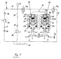
- the gas exchange valve designated by the reference number 1 of an internal combustion engine is to be opened by the hydraulic actuating device shown, i.e. starting from the position shown in the direction of arrow 2 from its valve seat 3 in the internal combustion engine cylinder head, which is only shown in fragments 4 are lifted off and then against it Arrow direction 2 closed again, i.e. back to the position shown brought in which the valve plate of the gas exchange valve 1 the valve seat 3 is seated.
- Each tappet-cylinder unit 20 consists of the basic structure a plunger 21 acting on the stem of the gas exchange valve 1, the within a cylinder 22 in or against the direction of arrow 2 longitudinally displaceable is led. Is in the interior of the cylinder 22 via a hydraulic circuit 10 branch line 11 hydraulic medium under high If pressure is introduced at a suitable point, this pressure is transferred the end face 21a of the tappet 21 facing away from the gas exchange valve 1, see above that the latter is moved downward in the direction of arrow 2. After yourself on the end face 21b of the tappet 21 facing the gas exchange valve 1 supports the gas exchange valve 1 with its unspecified stem, this will of course also change the gas exchange valve 1 desired moves.
- a stop 23 limits the maximum Displacement of the plunger 21 in the direction of arrow 2, in the Embodiments according to FIGS. 2, 3, this stop 23 carries a Cylinder 22 to the gas exchange valve 1 closing closing plate 22a, see above that this also limits the possible displacement of the plunger 21 is.
- the two hydraulic valves 14a, 14b are electrically operated, hydraulic Seat valves formed, which explained in more detail above has been.
- the hydraulic valve 14a provided in the supply line 13 is closed when de-energized (as shown here), while in the discharge line 15 provided hydraulic valve 14b (as shown) is open when de-energized.
- the two hydraulic valves 14a, 14b must therefore be energized, whereby hydraulic medium provided by the high pressure pump 12 get into the tappet-cylinder unit 20 via the spur line 11 and the Push the plunger 21 and thus the gas exchange valve 1 as required can.
- the gas exchange valve 1 If the gas exchange valve 1 is to be kept in its open position, so the energization of the hydraulic valve 14a can be switched off, whereby this assumes its closed position. By energizing further in The hydraulic valve 14b is held in its closed position, so that it continues sufficiently high hydraulic pressure on the end face 21a of the tappet 21 is applied to this in the position keeping the gas exchange valve 1 open hold.
- the gas exchange valve 1 should go in the opposite direction of the arrow 2 must be closed, so that it lies against the end face 21a Hydraulic medium are discharged from the tappet-cylinder unit 20 and again via the stub 11 and then through Switching off the energization of the hydraulic valve 14b released discharge line 15. As a result, the hydraulic pressure on the end face 21a of the Ram 21 removed.
- Hydraulic valves 14a, 14b designed as hydraulic seat valves characterized by extremely short response times.
- the closing movement is in the embodiment of FIG. 1 the gas exchange valve 1 initiated by the valve closing spring 5, as soon as there is no more hydraulic pressure on the end face 21a of the plunger 21.
- the gas exchange valve 1 In order to abruptly put the gas exchange valve 1 with his Preventing valve disc on valve seat 3 is in the tappet-cylinder unit 20 a so-called. End position damper is provided, briefly below is described.
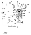
- the plunger 21 has a stepped piston shape and is immersed towards the end of the closing movement with its smaller-sized plunger section 21c in an end portion 22b of the cylinder which is adapted to this 22 a.
- the plunger 21 has a ball check valve 24 cavity 21e which can be filled with the hydraulic medium, wherein in the support area of the valve ball of the ball check valve 24 for Front end 21a of the larger cross-section plunger section 21d leading Branch holes 21f open.
- the valve ball of the ball check valve is located here 24 in the mouth area of a tappet section with a smaller cross section 21c extending, on the one hand with the stub 11 and on the other supply channel 21g connected to the cavity 21e. Therefor supports an unspecified, the valve ball of the ball check valve 24 presses against the mouth area of the feed channel 21g Spring element on the cavity 21e to the side of the gas exchange valve 1 final so-called spring rest 21h.
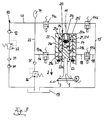
- the end face is ultimately in the second 21b of the plunger 21 with hydraulic line supply line 16, a hydraulic valve 17a is provided.
- a second is also planned Discharge line 18, through which the hydraulic medium from which the strin surface 21b of the plunger 21 which are not designated in greater detail with hydraulic pressure second hydraulic chamber ultimately in the hydraulic collecting tank 19 can be dissipated.
- This second discharge line 18 can be by means of of a hydraulic valve 17b can be opened or shut off.
- the hydraulic valves 17a, 17b are analogous to the hydraulic valves 14a, 14b again formed as an electrically operated hydraulic poppet valve, whereby the hydraulic valve 17a open as shown and the hydraulic valve 17b is closed when de-energized.
- the two hydraulic valves 17a, 17b can be controlled just as easily and quickly as the hydraulic valves 14a, 14b, which has already been explained above in connection with these. Otherwise, the second discharge line 18 opens into the first discharge line 15 and thus ultimately again in the hydraulic collecting tank 19.
- the high pressure pump 12 Preferably comes as the hydraulic medium to actuate the gas exchange valve 1 the lubricating oil Internal combustion engine, not shown, used. With the hydraulic collecting tank 19 is therefore the oil pan of the internal combustion engine. A conventional internal combustion engine lubricating oil pump is therefore also provided 30, here as a pre-feed pump for the high pressure pump 12 acts. Downstream one on the pressure side of the lubricating oil pump 30 provided oil filter 31 is a conventional lubricating oil pressure control valve 32 provided, downstream of it and upstream of the high pressure pump 12 not Branch shown shown branch to the lubrication points of the internal combustion engine to lead.
- a partial flow of the downstream of the lubricating oil pressure control valve 32 is present Lubricating oil is used as the hydraulic medium by the high pressure pump 12 sucked in, which, like the lubricating oil pump 30, mechanically can be driven by the internal combustion engine, but alternatively also as an electrically driven radial piston pump or axial piston pump can be trained.
- the feed line already mentioned leads on the pressure side 13 to the hydraulic valve 14a, upstream of which a branch line 33 branches off, the one hand a pressure accumulator 34 either continuously or alternatively also connectable in the hydraulic circuit 10, and the other hand also the second feed line 16 in the exemplary embodiments 2, 3 supplied with hydraulic medium. Downstream of the junction this second supply line 16 is a further filter in the branch line 33 35 and downstream of which a pressure relief valve 36 for each High-pressure part of the hydraulic circuit 10, provided the derivative of the pressure relief valve 36 again in the hydraulic reservoir 19 opens.
- the temperature of the hydraulic medium circulated in the hydraulic circuit 10 can vary in a wide range, especially when used as a hydraulic medium the lubricating oil of the internal combustion engine is used. Its temperature can be between -40 ° C and + 150 ° C. Around resulting viscosity differences, for precise control the hydraulic gas exchange valve actuating device is to be able to compensate at least essentially, is the working point this pressure relief valve 36 depending on the Temperature of the hydraulic medium (in a preferred embodiment) changeable. With this temperature-controlled pressure relief valve 36 the hydraulic pressure can be increased for a short time, as long as until the hydraulic medium has reached a sufficient operating temperature.
- a hydraulic circuit 10, which is not shown, can also be integrated Heat storage, which is preferably designed as a latent heat storage can be.
- This heat storage can in particular upstream of the High-pressure pump 12 must be installed and represents in the hydraulic circuit 10 thus relatively warm hydraulic medium even when the internal combustion engine is cold started available so that the actuation of the gas exchange valve 1 by the tappet-cylinder unit 20 due to the then lower Viscosity of the hydraulic medium can be done as desired.
- an electronic control unit due to which Signals the hydraulic valves 14a, 14b (and possibly 17a, 17b) the requirements be switched accordingly.
- the im Hydraulic circuit 10 circulated volume flow can together with the information about the switching status of the individual hydraulic valves electronic control unit also the respective position of the gas exchange valve Calculate 1.
- the pendulum effects of the hydraulic fluid column in particular in the Supply line 13 are taken into account, such that taking advantage of this Pendulum effects of the energy expenditure, in particular of the high pressure pump 12 is minimized.
- the plunger 21 can also be provided in this way Apply hydraulic medium that the gas exchange valve 1 - at least in the embodiment of FIG. 1 - in particular during its opening movement takes off from the plunger 21.
- Fig. 1 shows furthermore that for several to be operated in the same direction Gas exchange valves 1 of an internal combustion engine cylinder a plurality of tappet-cylinder units 20 with a single supply line 13 (possibly also 16) and a single discharge line 15 (possibly also 18) are provided.
- these two tappet-cylinder units 20 one Internal combustion engine cylinders, but all tappet-cylinder units 20 a multi-cylinder internal combustion engine, which then the several Actuate gas exchange valves 1 individually, in a common assembly bar be arranged, in which also the respectively assigned hydraulic valves 14a, 14b (and possibly 17a, 17b) can be provided to keep assembly and maintenance costs low,
- valve closing spring 5 can be a conventional coil spring, alternatively but also be a gas (pressure) spring.
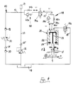
- the gas exchange valve 1 If the gas exchange valve 1 is to be kept in its open position, so the energization of the hydraulic valve 14a can be switched off, whereby this assumes its closed position. By energizing further in the hydraulic valve 14b is held in its closed position, so that continues sufficiently high hydraulic pressure on the gas exchange valve 1 facing away Face of the plunger 21 abuts this in the gas exchange valve 1 hold open position. Should be in a next one Step the gas exchange valve 1 is closed in the direction of the arrow 2, so the hydraulic medium lying against the end face mentioned must be made of the plunger-cylinder unit 20 are discharged via the discharge line 15, which is then switched off by energizing the hydraulic valve 14b is released. As a result, the hydraulic pressure at the gas exchange valve 1 facing away from the plunger 21 removed.
- the desired movement of the gas exchange valve 1 can thus be initiated by the simplest switching operations, it being pointed out that the hydraulic valves 14a, 14b designed as hydraulic seat valves are distinguished by extremely short response times.
- the closing movement of the gas exchange valve 1 is initiated by the valve closing spring 5 as soon as there is no longer any hydraulic pressure on the end face of the plunger 21 facing away from the gas exchange valve 1.
- a so-called end position damper (not shown in FIG. 4) can be provided in the tappet-cylinder unit 20.
- the pressure increasing member 38 is a so-called porous wall ", ie it consists of a check valve 38a which opens towards the tappet-cylinder unit 20 (and consequently blocks in the opposite direction), to which a line piece 38c having a throttle point 38b is connected in parallel.
- a check valve 38a which opens towards the tappet-cylinder unit 20 (and consequently blocks in the opposite direction)
- a line piece 38c having a throttle point 38b is connected in parallel.
- outlet 38d of the pressure-increasing element 38 the line branch containing the check valve 38a and the line section 38c containing the throttle point 38b are brought together again.
- the pressure increase member 38 and the length L 2 of that line section of the supply line 13 'that connects the outlet 38d of the pressure increase member 38 to the tappet-cylinder unit 20 is designed so that the known water hammer principle can be used to significantly increase the pressure upstream of the To achieve tappet-cylinder unit 20.
- the corresponding calculation formulas for this can be found, for example, in the literature cited above (E.
- the length L 1 between the unspecified inlet side of the pressure-increasing element 38 (on this inlet side the check valve 38a and the throttle point 38b or the associated line piece 38c branches) can also have an influence Hydraulic valve 14a controlling hydraulic medium is suitably switched, the pressure surge principle or water hammer principle in the hydraulic system upstream of the tappet-cylinder unit 20 is used to move the tappet 21 and thus the gas exchange valve 1 as desired with the lowest possible delivery rate of the high-pressure pump 12, ie to accelerate it .
- this hydraulic valve 14a should open very quickly and at the same time open up a sufficiently large cross section to allow the required volume of hydraulic medium to flow quickly into the tappet-cylinder unit 20.
- An equally rapid subsequent closing of the hydraulic valve 14a then leads to the formation of the desired pressure surge in the line section of the supply line 13 ′ designated L 2 .
- L 2 the desired pressure surge in the line section of the supply line 13 ′ designated L 2 .
- an additional vibration damper unit 40 consisting of a check valve 40a and a line section with a throttle point 40b connected in parallel to it, is (optionally) provided in its supply line 13.
- this vibration damper unit 40 also acts as a porous wall and prevents secondary waves, which arise due to the pressure surges in the supply line 13 ', from propagating via the open hydraulic valve 14a in the supply line 13 to the high-pressure pump 12.
- L 3 denotes that section of the feed line 13 which acts as an acceleration line section.
- the same pressure-increasing element 38 is provided downstream of the hydraulic valve 14a that controls the supply of hydraulic medium to the tappet-cylinder unit 20, and the same pressure damper unit 40 is provided upstream thereof as in the exemplary embodiment according to FIG.
- the already described length ratios of the hydraulic lines concerned namely in particular of the section of the supply line 13 ′ designated L 2 , are fundamentally similar.
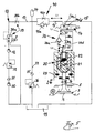
- the two hydraulic valves 14a, 14b are combined here in a 4/3-way slide valve 14.
- FIG. 5 also shows in the hydraulic circuit 10 downstream of the high pressure pump 12 arranged and on the temperature of the hydraulic medium responsive proportional pressure control unit 39.
- This pressure control unit 39 consists of a proportional pressure control valve 39a and one of these downstream aperture 39b.
- the proportional pressure control valve 39a is used as the controlled variable, the temperature of the hydraulic medium, so that with this temperature-controlled pressure control unit 39 regardless of the current one Temperature of the hydraulic medium is essentially always the same Switching behavior of the hydraulic valves 14a, 14b and thus an essentially Always the same sequence of movements of the tappet-cylinder unit 20 actuated gas exchange valve 1 can be achieved.
Landscapes
- Engineering & Computer Science (AREA)
- Mechanical Engineering (AREA)
- General Engineering & Computer Science (AREA)
- Valve Device For Special Equipments (AREA)
Abstract
Description
Die Lösung dieser Aufgabe ist dadurch gekennzeichnet, daß sowohl in der Zufuhrleitung als auch in der Abfuhrleitung ein als hydraulisches Sitzventil ausgebildetes Hydraulik-Ventil vorgesehen ist, wobei dasjenige in der Zufuhrleitung stromlos geschlossen und dasjenige in der Abfuhrleitung stromlos offen ist. Vorteilhafte Aus- und Weiterbildungen sind Inhalt der Unteransprüche.

Wie bereits erwähnt, wird bei beiden Ausführungsbeispielen die Schließbewegung des Gaswechselventiles 1 durch die Ventilschließfeder 5 initiiert, sobald auf der dem Gaswechselventil 1 abgewandten Stirnfläche des Stößels 21 kein Hydraulikdruck mehr anliegt. Um dabei ein zu abruptes Aufsetzen des Gaswechselventiles 1 mit seinem Ventilteller auf dem Ventilsitz 3 zu verhindern, kann in der Stößel-Zylinder-Einheit 20 ein an sich bekannter (in Fig. 4 nicht gezeigter) sog. Endlagendämpfer vorgesehen sein.
- 1
- Gaswechselventil
- 2
- Pfeilrichtung
- 3
- Ventilsitz
- 4
- Brennkraftmaschinen-Zylinderkopf
- 5
- Ventilschließfeder
- 6
- Ventilfederteller
- 10
- Hydraulik-Schaltkreis
- 11
- Stichleitung
- 12
- Hochdruckpumpe
- 13
- Zufuhrleitung
- 13'
- Versorgungsleitung
- 14
- 4/3-Wege-Schieberventil, 14a und 14b enthaltend
- 14a
- Hydraulikventil, die Zufuhr von Hydraulikmedium steuernd
- 14b
- Hydraulikventil, die Abfuhr von Hydraulikmedium steuernd
- 15
- Abfuhrleitung
- 16
- zweite Zufuhrleitung
- 17a
- Hydraulikventil in 16
- 17b
- Hydraulikventil in 18
- 18
- zweite Abfuhrleitung
- 19
- Hydrauliksammelbehälter
- 20
- Stößel-Zylinder-Einheit
- 2
- 1 Stößel
- 21a
- Stirnfläche von 21, dem Ventil 1 abgewandt
- 21b
- Stirnfläche von 21, dem Ventil 1 zugewandt
- 21c
- querschnittskleinerer Stößelabschnitt
- 21d
- querschnittsgrößerer Stößelabschnitt
- 21e
- Hohlraum
- 21f
- Stichbohrung
- 21g
- Zufuhrkanal
- 21h
- Federauflage
- 22
- Zylinder
- 22a
- Schließplatte
- 22b
- Endabschnitt, an 21c angepaßt
- 23
- Anschlag
- 24
- Kugelrückschlagventil
- 30
- Brennkraftmaschinen-Schmierölpumpe
- 31
- Ölfilter
- 32
- Schmieröl-Druckregelventil
- 33
- Zweigleitung
- 34
- Druckspeicher
- 35
- Filter
- 36
- Druckbegrenzungsventil
- 38
- Drucksteigerungsglied
- 38a
- Rückschlagventil
- 38b
- Drosselstelle
- 38c
- Leitungsstück
- 38d
- Ausgang von 38
- 39
- Proportional-Druckregeleinheit
- 39a
- Proporional-Druckregelventil
- 39b
- Blende
- 40
- Schwingungstilger-Einheit
- 40a
- Rückschlagventil
- 40b
- Drosselstelle
- L2
- Länge desjenigen Abschnittes von (13'), der (38d) mit (20) verbindet
Claims (14)
- Hydraulische Betätigungsvorrichtung für ein Brennkraftmaschinen-Gaswechselventil (1), auf welches ein in einem Zylinder (22) geführter Stößel (21) einwirkt, der zum Öffnen des Gaswechselventiles (1) auf seiner diesem abgewandten Stirnfläche (21a) gesteuert durch zumindest ein elektrisch betätigtes Hydraulik-Ventil mit von einer Hochdruckpumpe (12) über eine Zufuhrleitung (13) bereitgestelltem Hydraulikmedium beaufschlagt wird, und wobei mit einem späteren Schließen des Gaswechselventiles (1) dieses Hydraulikmedium aus der Stößel-Zylinder-Einheit (20) über eine Abfuhrleitung (15) abgeführt wird,
dadurch gekennzeichnet, daß sowohl in der Zufuhrleitung (13) als auch in der Abfuhrleitung (15) ein als hydraulisches Sitzventil ausgebildetes Hydraulik-Ventil (14a, 14b) vorgesehen ist, wobei dasjenige in der Zufuhrleitung (13) stromlos geschlossen und dasjenige in der Abfuhrleitung (15) stromlos offen ist - Hydraulische Betätigungsvorrichtung nach Anspruch 1,
dadurch gekennzeichnet daß der Stößel (21) zum Schließen des Gaswechselventiles (1) auf seiner diesem zugewandten Stirnfläche (21b) mit über eine zweite Zufuhrleitung (16) bereitgestelltem Hydraulikmedium beaufschlagt wird. - Hydraulische Betätigungsvorrichtung nach Anspruch 2,
dadurch gekennzeichnet, daß das über die zweite Zufuhrleitung (16) herangeführte Hydraulikmedium mit einem späteren Öffnen des Gaswechselventiles (1) aus der Stößel-Zylinder-Einheit (20) über eine zweite Abfuhrleitung (18) abgeführt wird, wobei sowohl in der zweiten Zufuhrleitung (16) als auch in der zweiten Abfuhrleitung (18) ein als elektrisches hydraulisches Sitzventil ausgebildetes Hydraulik-Ventil (17a, 17b) vorgesehen ist, wobei dasjenige in der zweiten Zufuhrleitung (16) stromlos offen und dasjenige in der zweiten Abfuhrleitung (18) stromlos geschlossen ist. - Hydraulische Betätigungsvorrichtung nach einem der vorangegangenen Ansprüche mit einem stromab der Hochdruckpumpe (12) vorgesehenem Druckbegrenzungsventil (36),
dadurch gekennzeichnet, daß der Arbeitspunkt des Druckbegrenzungsventiles (36) in Abhängigkeit von der Temperatur des Hydraulikmediums veränderbar ist, um temperaturabhängige Viskositätsunterschiede auszugleichen. - Hydraulische Betätigungsvorrichtung nach einem der vorangegangenen Ansprüche,
dadurch gekennzeichnet, daß der Hydraulikkreislauf über einen insbesondere als Latentwärmespeicher ausgebildeten Wärmespeicher geführt ist. - Hydraulische Betätigungsvorrichtung nach einem der vorangegangenen Ansprüche,
gekennzeichnet durch eine elektronische Steuereinheit zur Betätigung der Hydraulikventile (14a, 14b, 17a, 17b), die aus dem durchgesetzten Volumenstrom des Hydraulikmediums die jeweilige Position des Gaswechselventiles (1) errechnet. - Hydraulische Betätigungsvorrichtung nach einem der vorangegangenen Ansprüche,
dadurch gekennzeichnet, daß bei der Ansteuerung der Hydraulikventile (14a, 14b, 17a, 17b) Pendeleffekte der Hydraulikmedium-Fluidsäule in der Zufuhrleitung (13, 16) zur Verminderung des Energieaufwandes berücksichtigt werden. - Hydraulische Betätigungsvorrichtung nach einem der vorangegangenen Ansprüche,
dadurch gekennzeichnet, daß der Stößel (21) solchermaßen mit Hydraulikmedium beaufschlagt wird, daß das Gaswechselventil (1) insbesondere bei seiner Öffnungsbewegung vom Stößel (21) abhebt. - Hydraulische Betätigungsvorrichtung nach einem der vorangegangenen Ansprüche,
dadurch gekennzeichnet, daß für mehrere gleichsinnig zu betätigende Gaswechelventile (1) eines Brennkraftmaschinen-Zylinders mehrere Stößel-Zylinder-Einheiten (20) mit einer gemeinsamen Zufuhrleitung (13, 16) und Abfuhrleitung (18) mit jeweils einem Hydraulik-Ventil (14a, 14b, 17a, 17b) vorgesehen sind. - Hydraulische Betätigungsvorrichtung nach einem der vorangegangenen Ansprüche,
dadurch gekennzeichnet, daß in einer sich an die Zufuhrleitung (13) anschließenden Versorgungsleitung (13') stromab des die Zufuhr von Hydraulikmedium steuernden Hydraulik-Ventiles (14a) ein Drucksteigerungsglied (38), bestehend aus einem Rückschlagventil (38a) und einem zu diesem parallel geschalteteten Leitungsstück (38c) mit Drosselstelle (38b), vorgesehen ist. - Hydraulische Betätigungsvorrichtung nach Anspruch 10,
dadurch gekennzeichnet, daß die Länge (L2) desjenigen Leitungsabschnittes der Versorgungsleitung (13'), der den Ausgang (38d) des Drucksteigerungsgliedes (38) mit der Stößel-Zylinder-Einheit (20) verbindet, so gewählt ist, daß das bekannte Wasserschlagprinzip nutzbar ist, um eine signifikante Drucküberhöhung stromauf der Stößel-Zylinder-Einheit (20) zu erzielen. - Hydraulische Betätigungsvorrichtung nach Anspruch 10 oder 11,
dadurch gekennzeichnet, daß stromauf des die Zufuhr von Hydraulikmedium steuernden Hydraulik-Ventiles (14a) in dessen Zufuhrleitung (13) eine zusätzliche Schwingungstilger-Einheit (40), bestehend aus einem Rückschlagventil (40a) und einem zu diesem parallel geschalteteten Leitungsstück mit Drosselstelle (40b), vorgesehen ist. - Hydraulische Betätigungsvorrichtung nach einem der vorangegangenen Ansprüche,
dadurch gekennzeichnet, daß die beiden die Zufuhr und die Abfuhr von Hydraulikmedium steuernden Hydraulik-Ventile (14a, 14b) in einem 4/3-Wege-Schieberventil (14) zusammengefasst sind. - Hydraulische Betätigungsvorrichtung nach einem der vorangegangenen Ansprüche,
dadurch gekennzeichnet, daß stromab der Hochdruckpumpe (12) eine auf die Temperatur des Hydraulikmediums ansprechende Proportional-Druckregeleinheit (39) vorgesehen ist.
Applications Claiming Priority (4)
| Application Number | Priority Date | Filing Date | Title |
|---|---|---|---|
| DE19749303 | 1997-11-07 | ||
| DE19749303A DE19749303A1 (de) | 1997-11-07 | 1997-11-07 | Hydraulische Betätigungsvorrichtung für ein Brennkraftmaschinen-Gaswechselventil |
| DE19752053A DE19752053A1 (de) | 1997-11-25 | 1997-11-25 | Hydraulische Betätigungsvorrichtung für ein Gaswechselventil einer Brennkraftmaschine |
| DE19752053 | 1997-11-25 |
Publications (2)
| Publication Number | Publication Date |
|---|---|
| EP0915235A2 true EP0915235A2 (de) | 1999-05-12 |
| EP0915235A3 EP0915235A3 (de) | 1999-06-16 |
Family
ID=26041420
Family Applications (1)
| Application Number | Title | Priority Date | Filing Date |
|---|---|---|---|
| EP98119578A Withdrawn EP0915235A3 (de) | 1997-11-07 | 1998-10-16 | Hydraulische Betätigungsvorrichtung für ein Brennkraftmaschinen-Gaswechselventil |
Country Status (1)
| Country | Link |
|---|---|
| EP (1) | EP0915235A3 (de) |
Cited By (4)
| Publication number | Priority date | Publication date | Assignee | Title |
|---|---|---|---|---|
| DE19928560C2 (de) * | 1999-06-22 | 2002-02-07 | Bayerische Motoren Werke Ag | Drehmomentregelsystem für Brennkraftmaschinen in Kraftfahrzeugen mit einer Betätigungsvorrichtung zur variablen Ventilsteuerung |
| WO2003008770A1 (de) * | 2001-07-17 | 2003-01-30 | Robert Bosch Gmbh | Elektrohydraulische ventilsteuerung |
| EP1491731A1 (de) * | 2003-06-23 | 2004-12-29 | Magneti Marelli Powertrain S.p.A. | Elektrohydraulische Ventilbetätigungsvorrichtung einer Brennkraftmaschine |
| EP1770247A3 (de) * | 2005-09-28 | 2010-10-06 | Dell'orto S.P.A. | Elektrohydraulischer variabler Ventilaktuator und Verfahren zur Betätigung von Ventilen einer Brennkraftmaschine |
Citations (1)
| Publication number | Priority date | Publication date | Assignee | Title |
|---|---|---|---|---|
| DE2010291A1 (de) | 1970-03-05 | 1971-09-23 | Robert Bosch Gmbh, 7000 Stuttgart | Steuerung von Ein- und Auslaßventilen bei Brennkraftmaschinen durch Flüssigkeit |
Family Cites Families (2)
| Publication number | Priority date | Publication date | Assignee | Title |
|---|---|---|---|---|
| DE3736595A1 (de) * | 1987-10-29 | 1989-05-11 | Teves Gmbh Alfred | Hydraulisch betaetigte ventilsteuerung fuer verbrennungsmotoren |
| GB8729657D0 (en) * | 1987-12-19 | 1988-02-03 | Lucas Ind Plc | Valve actuation system |
-
1998
- 1998-10-16 EP EP98119578A patent/EP0915235A3/de not_active Withdrawn
Patent Citations (1)
| Publication number | Priority date | Publication date | Assignee | Title |
|---|---|---|---|---|
| DE2010291A1 (de) | 1970-03-05 | 1971-09-23 | Robert Bosch Gmbh, 7000 Stuttgart | Steuerung von Ein- und Auslaßventilen bei Brennkraftmaschinen durch Flüssigkeit |
Cited By (7)
| Publication number | Priority date | Publication date | Assignee | Title |
|---|---|---|---|---|
| DE19928560C2 (de) * | 1999-06-22 | 2002-02-07 | Bayerische Motoren Werke Ag | Drehmomentregelsystem für Brennkraftmaschinen in Kraftfahrzeugen mit einer Betätigungsvorrichtung zur variablen Ventilsteuerung |
| WO2003008770A1 (de) * | 2001-07-17 | 2003-01-30 | Robert Bosch Gmbh | Elektrohydraulische ventilsteuerung |
| US6892683B2 (en) | 2001-07-17 | 2005-05-17 | Robert Bosch Gmbh | Electrohydraulic valve controller |
| EP1491731A1 (de) * | 2003-06-23 | 2004-12-29 | Magneti Marelli Powertrain S.p.A. | Elektrohydraulische Ventilbetätigungsvorrichtung einer Brennkraftmaschine |
| US6997147B2 (en) | 2003-06-23 | 2006-02-14 | Magneti Marelli Powertrain S.P.A. | Electrohydraulic unit for actuating the valves of an endothermic engine |
| CN100406687C (zh) * | 2003-06-23 | 2008-07-30 | 玛涅蒂玛瑞利动力系公开有限公司 | 用于驱动吸热型发动机的气门的电液单元 |
| EP1770247A3 (de) * | 2005-09-28 | 2010-10-06 | Dell'orto S.P.A. | Elektrohydraulischer variabler Ventilaktuator und Verfahren zur Betätigung von Ventilen einer Brennkraftmaschine |
Also Published As
| Publication number | Publication date |
|---|---|
| EP0915235A3 (de) | 1999-06-16 |
Similar Documents
| Publication | Publication Date | Title |
|---|---|---|
| EP0736672B1 (de) | Verfahren zur Motorbremsung mit einem 4-Takt-Verbrennungsmotor | |
| DE19853355C1 (de) | Hydraulisch steuerbares Hubventil | |
| EP1654455B1 (de) | Steuerventil für einen einen drucküberbesetzer enthaltenden kraftstoffinjektor | |
| DE19621719C1 (de) | Hydraulische Ventilsteuervorrichtung | |
| DE19650987A1 (de) | Bremssystem für einen Innenverbrennungsmotor | |
| DE19716750C2 (de) | Motorbremssystem für einen Verbrennungsmotor | |
| DE10242866B4 (de) | Variabler Ventiltrieb | |
| EP1203153B1 (de) | Steuerventilanordnung zum einsatz in einem kraftstoffinjektor für verbrennungsmotoren | |
| EP1831540B1 (de) | Kraftstoffinjektor mit direkt angesteuertem einspritzventilglied | |
| WO2003027450A1 (de) | Hydraulisch gesteuerter aktuator zur betätigung eines ventils | |
| WO1999018349A1 (de) | Direktgesteuertes einspritzventil, insbesondere kraftstoffeinspritzventil | |
| EP1558843B1 (de) | Kraftstoff-einspritzeinrichtung für brennkraftmaschinen | |
| DE3939002A1 (de) | Hydraulische ventilsteuervorrichtung fuer eine mehrzylinder-brennkraftmaschine | |
| EP1185785B1 (de) | Einspritzsystem | |
| EP1925812B1 (de) | Kraftstoffeinspritzventil für Brennkraftmaschinen | |
| DE112006002281T5 (de) | Einspritzvorrichtung für ein einzelnes Strömungsmittel mit Ratenformungsfähigkeit | |
| CH671073A5 (de) | ||
| WO1998048151A1 (de) | Hydraulische steuervorrichtung für wenigstens ein hubventil | |
| EP1430201B1 (de) | Verfahren zum betreiben einer elektrohydraulischen ventilsteuerung einer brennkraftmaschine, computerprogramm sowie steuer- und regelgerät zum betreiben einer brennkraftmaschine | |
| DE102004022447A1 (de) | Hydraulischer Steller und Verfahren zum Betreiben eines hydraulischen Stellers | |
| EP1485585B1 (de) | Vorrichtung zur steuerung eines gaswechselventils | |
| EP3446006A1 (de) | VENTIL ZUM VERSCHLIEßEN UND ÖFFNEN EINES LEITUNGSSYSTEMS | |
| DE19949525B4 (de) | Druckübersetzer für ein Kraftstoffeinspritzsystem für Brennkraftmaschinen mit hydraulisch unterstützter Wiederbefüllung | |
| WO2004005679A1 (de) | Vorrichtung zur steuerung von gaswechselventilen | |
| WO2002029213A1 (de) | Abschaltbares abstützelement |
Legal Events
| Date | Code | Title | Description |
|---|---|---|---|
| PUAI | Public reference made under article 153(3) epc to a published international application that has entered the european phase |
Free format text: ORIGINAL CODE: 0009012 |
|
| PUAL | Search report despatched |
Free format text: ORIGINAL CODE: 0009013 |
|
| AK | Designated contracting states |
Kind code of ref document: A2 Designated state(s): DE FR GB IT |
|
| AX | Request for extension of the european patent |
Free format text: AL;LT;LV;MK;RO;SI |
|
| AK | Designated contracting states |
Kind code of ref document: A3 Designated state(s): AT BE CH CY DE DK ES FI FR GB GR IE IT LI LU MC NL PT SE |
|
| AX | Request for extension of the european patent |
Free format text: AL;LT;LV;MK;RO;SI |
|
| 17P | Request for examination filed |
Effective date: 19991106 |
|
| AKX | Designation fees paid |
Free format text: DE FR GB |
|
| RBV | Designated contracting states (corrected) |
Designated state(s): DE FR GB IT |
|
| 17Q | First examination report despatched |
Effective date: 20020205 |
|
| STAA | Information on the status of an ep patent application or granted ep patent |
Free format text: STATUS: THE APPLICATION IS DEEMED TO BE WITHDRAWN |
|
| 18D | Application deemed to be withdrawn |
Effective date: 20020618 |