EP0910784B1 - Technique d'inspection de courant de foucault - Google Patents
Technique d'inspection de courant de foucault Download PDFInfo
- Publication number
- EP0910784B1 EP0910784B1 EP97934475A EP97934475A EP0910784B1 EP 0910784 B1 EP0910784 B1 EP 0910784B1 EP 97934475 A EP97934475 A EP 97934475A EP 97934475 A EP97934475 A EP 97934475A EP 0910784 B1 EP0910784 B1 EP 0910784B1
- Authority
- EP
- European Patent Office
- Prior art keywords
- coils
- wall
- receiver
- eddy current
- electromagnetic field
- Prior art date
- Legal status (The legal status is an assumption and is not a legal conclusion. Google has not performed a legal analysis and makes no representation as to the accuracy of the status listed.)
- Expired - Lifetime
Links
- 238000000034 method Methods 0.000 title claims description 6
- 238000007689 inspection Methods 0.000 title description 5
- 230000005672 electromagnetic field Effects 0.000 claims description 29
- 239000004020 conductor Substances 0.000 claims description 11
- 230000003068 static effect Effects 0.000 claims description 7
- 239000003302 ferromagnetic material Substances 0.000 claims description 2
- 230000001939 inductive effect Effects 0.000 claims 1
- 238000005259 measurement Methods 0.000 description 13
- 239000000523 sample Substances 0.000 description 11
- 230000007797 corrosion Effects 0.000 description 9
- 238000005260 corrosion Methods 0.000 description 9
- 238000001514 detection method Methods 0.000 description 9
- 229910000831 Steel Inorganic materials 0.000 description 8
- 239000010959 steel Substances 0.000 description 8
- 238000010586 diagram Methods 0.000 description 6
- 238000009792 diffusion process Methods 0.000 description 5
- 230000000694 effects Effects 0.000 description 5
- 238000009413 insulation Methods 0.000 description 5
- 239000011810 insulating material Substances 0.000 description 4
- 239000004411 aluminium Substances 0.000 description 3
- 229910052782 aluminium Inorganic materials 0.000 description 3
- XAGFODPZIPBFFR-UHFFFAOYSA-N aluminium Chemical compound [Al] XAGFODPZIPBFFR-UHFFFAOYSA-N 0.000 description 3
- 230000008859 change Effects 0.000 description 3
- 238000004804 winding Methods 0.000 description 3
- 238000011088 calibration curve Methods 0.000 description 2
- 238000007796 conventional method Methods 0.000 description 2
- 230000004907 flux Effects 0.000 description 2
- 239000012774 insulation material Substances 0.000 description 2
- 239000000463 material Substances 0.000 description 2
- 230000035945 sensitivity Effects 0.000 description 2
- 239000010426 asphalt Substances 0.000 description 1
- 230000008901 benefit Effects 0.000 description 1
- 239000011248 coating agent Substances 0.000 description 1
- 238000000576 coating method Methods 0.000 description 1
- 230000007547 defect Effects 0.000 description 1
- 238000006073 displacement reaction Methods 0.000 description 1
- 239000003822 epoxy resin Substances 0.000 description 1
- 239000007788 liquid Substances 0.000 description 1
- 229910052751 metal Inorganic materials 0.000 description 1
- 239000002184 metal Substances 0.000 description 1
- 239000012811 non-conductive material Substances 0.000 description 1
- 235000012771 pancakes Nutrition 0.000 description 1
- 230000035699 permeability Effects 0.000 description 1
- 229920000647 polyepoxide Polymers 0.000 description 1
- 230000004044 response Effects 0.000 description 1
- 230000000630 rising effect Effects 0.000 description 1
- 239000007787 solid Substances 0.000 description 1
- 238000002604 ultrasonography Methods 0.000 description 1
- 230000000007 visual effect Effects 0.000 description 1
- 238000011179 visual inspection Methods 0.000 description 1
- XLYOFNOQVPJJNP-UHFFFAOYSA-N water Substances O XLYOFNOQVPJJNP-UHFFFAOYSA-N 0.000 description 1
Images


Classifications
-
- G—PHYSICS
- G01—MEASURING; TESTING
- G01N—INVESTIGATING OR ANALYSING MATERIALS BY DETERMINING THEIR CHEMICAL OR PHYSICAL PROPERTIES
- G01N27/00—Investigating or analysing materials by the use of electric, electrochemical, or magnetic means
- G01N27/72—Investigating or analysing materials by the use of electric, electrochemical, or magnetic means by investigating magnetic variables
- G01N27/82—Investigating or analysing materials by the use of electric, electrochemical, or magnetic means by investigating magnetic variables for investigating the presence of flaws
- G01N27/90—Investigating or analysing materials by the use of electric, electrochemical, or magnetic means by investigating magnetic variables for investigating the presence of flaws using eddy currents
- G01N27/904—Investigating or analysing materials by the use of electric, electrochemical, or magnetic means by investigating magnetic variables for investigating the presence of flaws using eddy currents with two or more sensors
-
- G—PHYSICS
- G01—MEASURING; TESTING
- G01B—MEASURING LENGTH, THICKNESS OR SIMILAR LINEAR DIMENSIONS; MEASURING ANGLES; MEASURING AREAS; MEASURING IRREGULARITIES OF SURFACES OR CONTOURS
- G01B7/00—Measuring arrangements characterised by the use of electric or magnetic techniques
- G01B7/02—Measuring arrangements characterised by the use of electric or magnetic techniques for measuring length, width or thickness
- G01B7/06—Measuring arrangements characterised by the use of electric or magnetic techniques for measuring length, width or thickness for measuring thickness
Definitions
- the present invention relates to inspecting an object of electrically conductive material.
- an object' is used to refer to operations such as measuring the thickness of the object, checking the object for the presence of sub-surface flaws and measuring the thickness of a layer of non-conductive material around the object.
- the object can be for example a wall of a container or the wall of a pipe.
- the effective thickness of an object for example, a wall of a steel container, a pipe or a vessel can be locally affected by external or internal corrosion.
- corrosion detection by visual inspection generally implies temporary removal of the insulation material, which is time consuming and expensive.
- European patent specification No. 321 112 discloses a container- or pipe-wall inspection device, wherein the wall is made of electrically conductive material and has a near surface, the inspection device comprising a non-static-signal transmitter for generating an electromagnetic field in the wall, and a receiver for measuring the variations of the eddy current generated by the non-static electromagnetic field and for producing a signal representing the decay of the eddy current.
- the decay of the received signal over a period of time is compared with the decay of a reference signal indicative of a known wall thickness.
- the transmitter includes an emitter coil and the receiver includes a receiver coil.
- the coils are wound around a core, and, during normal operation, the central longitudinal axis of the core is perpendicular to a surface of the wall.
- Japanese patent publication No. 06 186 207 teaches to enhance the detecting performance of coils and to improve the sensitivity of a probe for minute defects by utilizing the directions of currents flowing through the coils in an eddy-current flaw detecting probe using pancake coils.
- Figure 1 shows a probe 1 for inspecting an object of electrically conductive material, such as for measuring the thickness of a wall 2 of a pipe 3 in order to detect the presence of corrosion at the wall 2.
- the corrosion can be located at the outer or inner surface of the wall 2.
- a layer 5 of insulating material enclosed by a thin metal steel jacket 7 surrounding the layer 5 of insulating material is provided around the pipe 3.
- the probe 1 includes a device 9 for inspecting an object of electrically conductive material, which during normal operation, is held against the outer surface of the steel jacket 7.
- the device 9 for inspecting the object of electrically conductive material comprises a non-static-signal transmitter (not shown) for generating a non-static electromagnetic field in the object in the form of the wall 2 and a receiver (not shown) for measuring the variations of the eddy current generated by the non-. static electromagnetic field and for producing a signal representing the decay of the eddy current.
- the non-static-signal transmitter comprises at least two laterally spaced-apart emitters for emitting an electromagnetic field, in the form of a first emitter coil 11 and a second emitter coil 12, which are spaced apart in a direction lateral to the direction of their central longitudinal axes 13 and 14, respectively. Between the emitter coils 11 and 12 there is a relatively small gap 16. During normal operation the emitter coils are arranged parallel to a near surface 17 of the object in the form of the wall 2, so that their central longitudinal axes 13 and 14 are perpendicular to the near surface 17.
- the transmitter further includes means (not shown) which drive the emitters in the form of emitter coils 11 and 12.
- the receiver includes at least one receiver coil arranged to receive the electromagnetic field generated by the eddy current in the object in the form of the wall 2, in the form of a first receiver coil 20 and a second receiver coil 22, having central longitudinal axis 23 and 24, respectively.
- the receiver coils 20 and 22 are identical, and have a square cross-section. They are arranged substantially parallel to the near surface 17 of the object in the form of the wall 2.
- the pair of receiver coils 20, 22 is arranged aligned with the corresponding pair of emitter coils 11, 12, that is to say the central longitudinal axes 13 and 14, and 23 and 24 of the coils are substantially parallel to each other and extend in the same plane (that is the plane of drawing of Figure 2).
- the size of the receiver coils 20 and 22 is smaller than the size of the emitter coils 11 and 12 and the central longitudinal axes 23 and 24 of the receiver coils 20 and 22 extend between the central longitudinal axes 13 and 14 of the emitter coils 11 and 12.
- the voltage over the terminals of the receiver coils is the signal representing the decay of the eddy current in the object.
- the emitters in the form of emitter coils 11 and 12 are so driven that the resulting electromagnetic field in the central region, between the centres 25 of the emitters 11 and 12, is intensified.
- the central region is indicated with reference numeral 26. This is done by passing a current through each of the emitter coils 11 and 12 such that the direction of the currents in the emitter coils is not the same. In Figure 3 the direction of the currents is indicated by arrows A.
- the electromagnetic field in the central region 26 is intensified, that is to say it is stronger in a region between the emitter coils 11 and 12 and weaker outside the central region 26. Consequently in the object 2 there is a region 27 where the density of the electromagnetic field is larger than outside that region 27.
- the region 27 of increased density of the electromagnetic field will be called the detection region 27. In this way a better resolution is achieved and relatively small corrosion spots can be detected.
- the receiver coils 20 and 22 are connected in series and they are located at opposite sides of the gap 16 and of the detection region 27.
- each emitter coil 11 and 12 is substantially equal to the thickness of the insulation layer 5.
- the diameter of each emitter coil 11 and 12 is substantially equal to the thickness of the insulation layer 5.
- two emitter coils of 200 windings of 0.5 mm wire having a diameter of 70 mm are used.
- the gap 16 overlays the detection region 27 of the wall 2 of the pipe 3 which is to be checked for corrosion.
- FIG 4 is shown an alternative embodiment wherein the arrangement of emitter coils 41 and 42 is similar to the arrangement of emitter coils 11 and 12 shown in Figures 2 and 3. However, instead of two receiver coils being arranged in a plane parallel to that of the emitter coils, only one receiver coil 46 is provided.
- the receiver coil 46 is located between the emitter coils 41 and 42 and its central longitudinal axis 47 extends perpendicular to the central longitudinal axes 43 and 44 of the emitter coils 41 and 42.
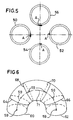
- FIG. 5 showing another arrangement of coils including a first pair of emitter coils 50 and 52 and a second pair of emitter coils 54 and 56, the pairs being arranged in mutually perpendicular directions.
- the arrow A indicates the directions of the electric currents in the emitter coils 50, 52, 54 and 56.
- the first pair of emitter coils 50 and 52 on one hand and the second pair of emitter coils 54 and 56 on the other hand induce eddy currents of increased density in different directions in the selected wall portion between the emitter coils 50, 52, 54 and 56.
- the eddy currents of increased density flow in mutually perpendicular directions.
- Each pair of emitter coils is provided with a corresponding pair of receiver coils (not shown), the receiver coils of each pair being of the same type and being arranged in the same manner with respect to the corresponding emitter coils as with reference to Figure 3.
- This embodiment has the advantage over the embodiment of Figure 3 that the device is even better focused on the wall portion of interest, and that the measurement is more symmetrical.
- any other suitable number of pairs of coils may be applied in an analogous way.
- a semi-circular bar of ferromagnetic material (not shown) is arranged within the emitter coils.
- the essence of the present invention is that the laterally spaced apart emitters are so driven that the resulting electromagnetic field in the central region, between the emitters, is intensified.
- the laterally spaced-apart emitters consist of an emitter coil in the form of an 8-shaped figure substantially parallel to a near surface of the object.
- a suitable non-static signal is a pulse.
- electric currents are induced to flow in the emitter coils 11 and 12 in opposite rotational directions.
- a constant current flows through the emitter coils 11 and 12 during each pulse time T.
- the current and its associated electromagnetic field are switched on and off at respectively the rising and falling edge of the pulse.
- the emitter coils 11 and 12 are sufficiently large that at least some of the electromagnetic field lines penetrate through the jacket 7, the insulating layer 5 and the wall 2 of the steel pipe 3.
- the electromagnetic field lines in the wall 2 will mainly be concentrated in the vicinity of the near surface 17.
- An electromagnetic flux change occurs when the electromagnetic field is switched on or off, which flux change induces an eddy current in the wall 2 of the pipe 3 near the external surface 7.
- the eddy currents resulting from the separate emitter coils 11 and 12 flow in opposite rotational directions in the wall 2, so that an eddy current of increased density results in the detection region 27 of the wall 2 of the pipe 3 below the gap 16.
- the generated eddy currents diffuse through the wall 2 and are reflected by the internal surface of the wall 2 back to the external surface 14.
- the pulse duration T is selected to be longer than the typical diffusion time to ensure that a step response is measured.
- the pulse duration range is typically between 50 and 300 ms, depending on the thickness of the wall 2 of the pipe 3.
- a pulsed eddy current will diffuse in the depth direction (i.e. towards the internal surface) and in the radial direction with respect to its own loop (i.e. outwards so as to increase the eddy current loop radius). Furthermore, a charge transport along the eddy current loop takes place. The diffusion velocity is approximately 100 times higher than the velocity of charge transport along the eddy current loop. This implies that an eddy current can diffuse through the wall 2 and reflect from the internal surface with only a minor charge displacement along the loop. The diffusion within the detection region 27 is therefore largely independent on the diffusion and current flow outside the detection region 27. This makes it possible to take measurements that are only sensitive for a fraction of the eddy current. Suitably the electronics, the emitter and receiver coils for fractional pulsed eddy current measurement are designed such that impedance changes do not influence the measurement.
- the receiver coils 20 and 22 are of smaller size than the emitter coils 11 and 12 so that the receiver coils 20 and 22 are only sensitive for field lines of eddy currents flowing in the detection region 27.
- the windings sense of the receiver coils 20 and 22 is such that an absolute probe for the eddy current field lines is created, i.e. the currents induced in the receiver coils 20 and 22 by the field lines enhance each other.
- a differential probe for noise 50/60 Hz
- the rectangular receiver coils 20 and 22 have a size of 30 mm by 30 mm by 2 mm, and have 100 windings of 0.1 mm wire.
- the signal representing the decay of the eddy currents is the voltage over the receiver coils, of which the amplitude A (in V, volts) is evaluated as a function of the time after the current and the associated electromagnetic field has been switched off at the fall of the pulse.
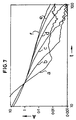
- Figure 7 shows a double-logarithmic diagram wherein the amplitudes A (in V) of six eddy current decay curves are plotted against the time t (in ms, milliseconds). The eddy current decays are obtained by applying a suitable eddy current probe to steel container walls of different thicknesses.
- the curves a, b, c, d, e and f show the decay for walls having a thickness of respectively 2, 4, 6, 8, 10 and 12 mm.
- the initial parts of the curves approach straight lines in the double-logarithmic diagram.
- Applicant has found that there is a linear relationship between the wall thickness and the time elapsed for the eddy current to decay from a first value to a second value, for example from 1 V to 0.05 V. This linear relationship is used in the present invention to measure the thickness of an unknown wall.
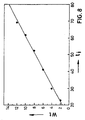
- FIG 8 is shown the substantially linear relationship between the wall thickness W t (in mm) and the time t i (in ms) elapsed until the curves of Figure 7 have decayed from 1 V to a selected magnitude of 0.05 V.
- the indicated dots correspond to the measurements pertaining to curves a, b, c, d, e, f of Figure 7.
- the eddy current probe can be calibrated by adjusting the magnitude of A so as to compensate for variations in permeability, temperature and wall curvature.
- a single measurement at a location with a known wall thickness is sufficient to find the magnitude of A.
- Small fluctuations in the magnitude of B may result in deviations in the wall thickness readings of approximately 10% (or approximately 1 mm). Such accuracy is sufficient for detection of corrosion under a layer of insulating material.
- the spacing is taken into account in the measurement by vertically shifting the curve in the double-logarithmic diagram in a manner that the amplitude of the signal has its first magnitude, for example 1 V, at a selected time such as between 10 and 20 ms, preferably 15 ms, after the end of a transmitter current pulse.
- the effect of the aluminium jacket surrounding the insulation layer is a change in amplitude and a retardation of the signal when the electromagnetic field penetrates the jacket.
- Amplitude changes do not affect the wall thickness measurement because they are compensated for by the amplitude measurement which is used to set the intersection point of the curves (at 15 ms in above example).
- Signal retardation occurs due to diffusion of eddy currents generated in the jacket. However retardation is only a few milliseconds, depending on the jacket material, and the slope of the signal decay curve is hardly affected by the presence of the jacket.
- the retardation can be compensated for by adjusting the magnitude of B, for example by ensuring that during calibration a jacket is present.
- the invention can be applied to objects of electrically conductive material of various structures, such as for example the wall of a pipe provided with insulation layers or the wall of a storage tank.
- the device according to the invention can for example be held against the lower side of the bottom by first excavating a substantially horizontal hole in the ground below the tank and subsequently moving the device through the borehole and against the bottom of the tank.
- the invention are of particular interest for application on vessels, pipes and plates which are provided with a layer of nonconducting material, such as bitumen or epoxy resin.
- the coating hinders inspection by conventional techniques (e.g. ultra sound or visual).
- applications involving extremely high or low temperatures of a wall to be inspected, which preclude the application of conventional techniques requiring direct contact with the wall, are of interest since no direct contact of such a wall with the probe used in the present invention is required.
Landscapes
- General Physics & Mathematics (AREA)
- Physics & Mathematics (AREA)
- Chemical & Material Sciences (AREA)
- General Health & Medical Sciences (AREA)
- Health & Medical Sciences (AREA)
- Life Sciences & Earth Sciences (AREA)
- Chemical Kinetics & Catalysis (AREA)
- Biochemistry (AREA)
- Analytical Chemistry (AREA)
- Electrochemistry (AREA)
- Immunology (AREA)
- Pathology (AREA)
- Investigating Or Analyzing Materials By The Use Of Magnetic Means (AREA)
- Measurement Of Length, Angles, Or The Like Using Electric Or Magnetic Means (AREA)
- Investigating Or Analyzing Materials By The Use Of Electric Means (AREA)
Claims (9)
- Utilisation d'un dispositif (9) pour inspecter une paroi (2) réalisée en un matériau électriquement conducteur représentant une surface proche (17), lequel dispositif (9) comprend un émetteur de signaux non statiques pour créer un champ magnétique dans la paroi (2) et un récepteur pour mesurer les variations des courants de Foucault créées par le champ magnétique non statique et pour délivrer un signal représentant l'atténuation des courants de Foucault, dans lequel l'émetteur de signaux non statique comprend au moins deux émetteurs (11, 12; 41, 42; 50, 52; 54, 56; 60, 62, 64, 66, 68, 70) écartés l'un de l'autre dans le sens latéral pour émettre un champ électromagnétique et entre lesquels est situé un interstice (16) relativement petit, lesquels émetteurs (11, 12; 41, 42; 50, 52; 54, 56; 60, 62, 64, 66, 68, 70) sont formés d'un ou de plusieurs bobinages et, en fonctionnement normal, sont alimentés de telle sorte que les courants dans des paires d'émetteurs (11, 12 ; 41, 42 ; 50, 52 ; 54, 56 ; 60, 62, 64, 66, 68, 70) écartés l'un de l'autre dans le sens latéral s'écoulent dans des directions opposées, caractérisée en ce que le récepteur comprend au moins une paire de bobinages de récepteur (20, 22) agencés pour recevoir le champ électromagnétique créé par les courants de Foucault dans la paroi (2), en ce que chaque paire de bobinages de récepteur (20, 22) est agencée de telle sorte que les axes longitudinaux centraux (13, 14) des bobinages d'émetteur (11, 12) et les axes longitudinaux centraux (23, 24) des bobinages de récepteur (20, 22) soient parallèles l'un à l'autre et en ce que la taille des bobinages de récepteur (20, 22) est plus petite que la taille des bobinages d'émetteur (11, 12) correspondants.
- Utilisation selon la revendication 1, dans laquelle l'émetteur de signaux non statiques comprend au moins une paire de bobinages d'émetteur (11, 12 ; 41, 42) écartés l'un de l'autre dans le sens latéral et qui, en fonctionnement normal, sont agencés essentiellement en parallèle à la surface proche (17) de la paroi (2).
- Utilisation d'un dispositif (9) pour inspecter une paroi (2) réalisée en un matériau électriquement conducteur représentant une surface proche (17), lequel dispositif (9) comprend un émetteur de signaux non statiques pour créer un champ magnétique dans la paroi (2) et un récepteur pour mesurer les variations des courants de Foucault créées par le champ magnétique non statique et pour délivrer un signal représentant l'atténuation des courants de Foucault, dans lequel l'émetteur de signaux non statique comprend au moins deux émetteurs (11, 12; 41, 42; 50, 52 ; 54, 56; 60, 62, 64, 66, 68, 70) écartés l'un de l'autre dans le sens latéral pour émettre un champ électromagnétique et entre lesquels est situé un interstice (16) relativement petit, lesquels émetteurs (11, 12 ; 41, 42 ; 50, 52 ; 54, 56 ; 60, 62, 64, 66, 68, 70) sont formés d'un ou de plusieurs bobinages, caractérisée en ce que les centres (59) des bobinages d'émetteur (60, 62, 64, 66, 68, 70) sont situés sur un arc semi-circulaire (71) situé, en fonctionnement normal, dans un plan perpendiculaire à la surface proche (17) de la paroi (2), et dans lequel les bobinages d'émetteur (60, 62, 64, 66, 68, 70) sont agencés perpendiculairement à l'arc.
- Utilisation selon la revendication 3, dans laquelle un barreau semi-circulaire en matériau magnétique est agencé à l'intérieur des bobinages d'émetteur.
- Utilisation selon la revendication 1, dans laquelle les émetteurs écartés l'un de l'autre dans le sens latéral sont constitués d'un bobinage qui présente la forme d'un chiffre 8 qui, en fonctionnement normal, est agencé essentiellement parallèlement à la surface proche (17) de la paroi (2).
- Utilisation d'un dispositif (9) pour inspecter une paroi (2) réalisée en un matériau électriquement conducteur représentant une surface proche (17), lequel dispositif (9) comprend un émetteur de signaux non statiques pour créer un champ magnétique dans la paroi (2) et un récepteur pour mesurer les variations des courants de Foucault créées par le champ magnétique non statique et pour délivrer un signal représentant l'atténuation des courants de Foucault, dans lequel l'émetteur de signaux non statique comprend au moins deux émetteurs (11, 12 ; 41, 42 ; 50, 52 ; 54, 56 ; 60, 62, 64, 66, 68, 70) écartés l'un de l'autre dans le sens latéral pour émettre un champ électromagnétique et entre lesquels est situé un interstice (16) relativement petit, lesquels émetteurs (11, 12; 41, 42; 50, 52; 54, 56; 60, 62, 64, 66, 68, 70) sont formés d'un ou de plusieurs bobinages et, en fonctionnement normal, sont alimentés de telle sorte que les courants dans des paires d'émetteurs (11, 12; 41, 42 ; 50, 52 ; 54, 56; 60, 62, 64, 66, 68, 70) écartés l'un de l'autre dans le sens latéral s'écoulent dans des directions opposées, caractérisée en ce que le récepteur comprend un bobinage de récepteur (46) qui est situé entre les bobinages d'émetteur (41, 42), l'axe longitudinal central (47) du bobinage de récepteur (46) s'étendant perpendiculairement aux axes longitudinaux centraux (43, 44) des bobinages d'émetteur (41, 42).
- Utilisation selon la revendication 1, dans laquelle le récepteur comprend au moins une paire de bobinage de récepteur (20, 22) comprenant un premier bobinage de récepteur (20) et un deuxième bobinage de récepteur (22) qui, en fonctionnement normal, sont agencés de chaque côté de l'interstice (16).
- Utilisation selon l'une quelconque des revendications 1 et 7, dans laquelle chaque bobinage de récepteur (20, 22) est situé entre les bobinages d'émetteur (11, 12) et la paroi (2).
- Procédé de mesure de l'épaisseur d'un objet en matériau électriquement conducteur, le procédé comprenant les étapes consistant à induire un courant de Foucault pulsé dans l'objet, à déterminer l'atténuation du courant de Foucault et à délivrer un signal représentant l'atténuation, et à déterminer l'épaisseur de l'objet à partir du signal, l'étape consistant à déterminer l'épaisseur de l'objet à partir du signal comprenant l'étape consistant à sélectionner une première grandeur et une deuxième grandeur plus petite de l'amplitude du signal, à mesurer la longueur de l'intervalle de temps au cours duquel le signal s'affaiblit depuis la première valeur jusqu'à la deuxième valeur et à déterminer l'épaisseur de l'objet (Wt) à partir de la longueur d'un intervalle de temps (ti) à l'aide de l'équation suivante :
Priority Applications (1)
| Application Number | Priority Date | Filing Date | Title |
|---|---|---|---|
| EP97934475A EP0910784B1 (fr) | 1996-07-12 | 1997-07-11 | Technique d'inspection de courant de foucault |
Applications Claiming Priority (4)
| Application Number | Priority Date | Filing Date | Title |
|---|---|---|---|
| EP96201978 | 1996-07-12 | ||
| EP96201978 | 1996-07-12 | ||
| PCT/EP1997/003815 WO1998002714A1 (fr) | 1996-07-12 | 1997-07-11 | Technique d'inspection de courant de foucault |
| EP97934475A EP0910784B1 (fr) | 1996-07-12 | 1997-07-11 | Technique d'inspection de courant de foucault |
Publications (2)
| Publication Number | Publication Date |
|---|---|
| EP0910784A1 EP0910784A1 (fr) | 1999-04-28 |
| EP0910784B1 true EP0910784B1 (fr) | 2002-05-22 |
Family
ID=8224185
Family Applications (1)
| Application Number | Title | Priority Date | Filing Date |
|---|---|---|---|
| EP97934475A Expired - Lifetime EP0910784B1 (fr) | 1996-07-12 | 1997-07-11 | Technique d'inspection de courant de foucault |
Country Status (9)
| Country | Link |
|---|---|
| US (1) | US6291992B1 (fr) |
| EP (1) | EP0910784B1 (fr) |
| JP (1) | JP4263244B2 (fr) |
| CN (2) | CN1155795C (fr) |
| DE (1) | DE69712759T2 (fr) |
| ES (1) | ES2177994T3 (fr) |
| NO (1) | NO331373B1 (fr) |
| RU (1) | RU2183008C2 (fr) |
| WO (1) | WO1998002714A1 (fr) |
Cited By (2)
| Publication number | Priority date | Publication date | Assignee | Title |
|---|---|---|---|---|
| US7514918B2 (en) | 2002-12-19 | 2009-04-07 | Shell Oil Company | Monitoring wall thickness |
| NL1044407B1 (nl) | 2022-08-30 | 2024-03-12 | Sixpec B V | Wervelstroomsonde met focusserende werking voor niet-destructief testen. |
Families Citing this family (67)
| Publication number | Priority date | Publication date | Assignee | Title |
|---|---|---|---|---|
| US6392421B1 (en) | 1998-06-11 | 2002-05-21 | Em-Tech Llc | Spectral EM frequency metallic thickness measurement using metallic transparencies |
| AUPP813499A0 (en) * | 1999-01-13 | 1999-02-04 | Rock Solid Research Pty. Ltd. | A subsurface pipeline inspection probe |
| US6573706B2 (en) * | 1999-11-18 | 2003-06-03 | Intellijoint Systems Ltd. | Method and apparatus for distance based detection of wear and the like in joints |
| KR100448444B1 (ko) * | 1999-12-29 | 2004-09-13 | 주식회사 포스코 | 위상배열방식의 와전류 감지기에 의한 압연강판의 두께와형상 및 평평도 측정장치 |
| US20030210041A1 (en) * | 2000-04-07 | 2003-11-13 | Le Cuong Duy | Eddy current measuring system for monitoring and controlling a chemical vapor deposition (CVD) process |
| US6762604B2 (en) | 2000-04-07 | 2004-07-13 | Cuong Duy Le | Standalone eddy current measuring system for thickness estimation of conductive films |
| US6741076B2 (en) | 2000-04-07 | 2004-05-25 | Cuong Duy Le | Eddy current measuring system for monitoring and controlling a CMP process |
| US6549006B2 (en) * | 2000-04-07 | 2003-04-15 | Cuong Duy Le | Eddy current measurements of thin-film metal coatings using a selectable calibration standard |
| US6538435B2 (en) * | 2000-08-24 | 2003-03-25 | Shell Oil Company | Method for detecting an anomaly in an object of electrically conductive material along first and second direction at inspection points |
| US6593737B2 (en) * | 2000-08-24 | 2003-07-15 | Shell Oil Company | Method for measuring the wall thickness of an electrically conductive object |
| US6707296B2 (en) | 2000-08-24 | 2004-03-16 | Shell Oil Company | Method for detecting cracks in electrically conducting material |
| WO2002033394A2 (fr) | 2000-10-16 | 2002-04-25 | Em-Tech Llc | Technique permettant de mesurer l'epaisseur d'un metal ferromagnetique a l'aide des signatures de permeabilite |
| WO2002050526A2 (fr) * | 2000-12-21 | 2002-06-27 | Shell Internationale Research Maatschappij B.V. | Mesure d'une propriete materielle d'un objet electroconducteur |
| DE10102577C1 (de) * | 2001-01-20 | 2002-06-20 | Univ Braunschweig Tech | Verfahren zur Zustandserkennung von elektrisch leitfähigen länglichen Spanngliedern |
| US20040239345A1 (en) * | 2001-05-01 | 2004-12-02 | Amini Bijan K. | Measurement of coatings on metal |
| KR100435989B1 (ko) * | 2001-12-01 | 2004-06-23 | (주)에스엔아이 | 와전류센서가 구비되는 측정장치 |
| AU2002228916A1 (en) * | 2001-12-10 | 2003-06-23 | Em-Tech Llc | Apparatus and method for the measurement of electrical properties of materials through non-magnetizable materials |
| DE60302653T2 (de) * | 2002-02-26 | 2006-06-14 | Shell Int Research | Messverfahren zum bestimmen eines oberflächenprofils |
| US7128803B2 (en) * | 2002-06-28 | 2006-10-31 | Lam Research Corporation | Integration of sensor based metrology into semiconductor processing tools |
| US7309618B2 (en) * | 2002-06-28 | 2007-12-18 | Lam Research Corporation | Method and apparatus for real time metal film thickness measurement |
| US20040011462A1 (en) * | 2002-06-28 | 2004-01-22 | Lam Research Corporation | Method and apparatus for applying differential removal rates to a surface of a substrate |
| US7205166B2 (en) * | 2002-06-28 | 2007-04-17 | Lam Research Corporation | Method and apparatus of arrayed, clustered or coupled eddy current sensor configuration for measuring conductive film properties |
| US7084621B2 (en) * | 2002-09-25 | 2006-08-01 | Lam Research Corporation | Enhancement of eddy current based measurement capabilities |
| US20050007108A1 (en) * | 2003-07-11 | 2005-01-13 | Teodor Dogaru | Probes and methods for detecting defects in metallic structures |
| US20050066739A1 (en) * | 2003-09-26 | 2005-03-31 | Lam Research Corporation | Method and apparatus for wafer mechanical stress monitoring and wafer thermal stress monitoring |
| US7005851B2 (en) * | 2003-09-30 | 2006-02-28 | General Electric Company | Methods and apparatus for inspection utilizing pulsed eddy current |
| JP4394415B2 (ja) * | 2003-10-24 | 2010-01-06 | 非破壊検査株式会社 | 電磁波パルスによる板厚相対比較方法及び板厚相対比較装置 |
| US7214941B2 (en) * | 2004-12-16 | 2007-05-08 | The Gillette Company | Crack detection in razor blades |
| DE102005051536A1 (de) * | 2005-04-27 | 2006-11-09 | Micro-Epsilon Messtechnik Gmbh & Co Kg | Berührungslos arbeitender Wirbelstromsensor und Verfahren zur Detektion von Messobjekten |
| US7282909B2 (en) * | 2005-06-29 | 2007-10-16 | Lam Research Corporation | Methods and apparatus for determining the thickness of a conductive layer on a substrate |
| CA2629829A1 (fr) | 2005-11-23 | 2007-05-31 | Shell Internationale Research Maatschappij B.V. | Procede de sequestration de dioxyde de carbone par carbonation minerale |
| KR100696991B1 (ko) * | 2006-01-25 | 2007-03-20 | 한국원자력연구소 | 투자율 측정법을 이용하여 증기발생기 전열관의 와전류를탐상하는 장치 및 방법 |
| FR2900471B1 (fr) * | 2006-04-26 | 2008-12-26 | Snecma Sa | Mesure des epaisseurs de paroi, notamment d'aube, par courants de foucault |
| EP2064515B1 (fr) | 2006-09-21 | 2014-11-26 | Shell Internationale Research Maatschappij B.V. | Contrôle par courants de foucault d'un objet conducteur de l'électricité |
| GB2450112B (en) * | 2007-06-12 | 2010-12-08 | Ge Inspection Technologies Ltd | Automatic lift-off compensation for pulsed eddy current inspection |
| JP5017038B2 (ja) * | 2007-09-26 | 2012-09-05 | 株式会社日立製作所 | 渦流検査装置及び渦流検査方法 |
| JP5011056B2 (ja) * | 2007-10-10 | 2012-08-29 | 株式会社日立製作所 | 渦流検査プローブ及び渦流検査装置 |
| JP2010019565A (ja) * | 2008-07-08 | 2010-01-28 | Hitachi-Ge Nuclear Energy Ltd | 渦電流探傷プローブ |
| KR100931935B1 (ko) * | 2008-10-07 | 2009-12-15 | (주)레이나 | Pec를 이용한 결함 측정장치를 이용한 측정방법 |
| JP2010185832A (ja) * | 2009-02-13 | 2010-08-26 | Tlv Co Ltd | パルス渦流探傷装置 |
| PT2409114E (pt) * | 2009-03-17 | 2013-05-22 | Abb Ab | Um método e um aparelho para a medição da espessura de uma camada de metal presente num objeto de metal |
| JP5188466B2 (ja) * | 2009-06-30 | 2013-04-24 | 株式会社日立製作所 | パルス励磁型渦電流探傷方法及びこれを用いたパルス励磁型渦電流探傷装置 |
| JP5513821B2 (ja) * | 2009-09-17 | 2014-06-04 | 株式会社荏原製作所 | 渦電流センサ、研磨装置、めっき装置、研磨方法、めっき方法 |
| CN101788260B (zh) * | 2010-03-18 | 2011-12-28 | 清华大学 | 一种金属薄膜厚度的电涡流测量方法 |
| CN101915805B (zh) * | 2010-07-12 | 2012-04-04 | 哈尔滨工业大学深圳研究生院 | 一种基于小波分析的夹芯板超声波检伤方法及应用 |
| US9057146B2 (en) * | 2010-08-24 | 2015-06-16 | Varian Semiconductor Equipment Associates, Inc. | Eddy current thickness measurement apparatus |
| EP2612105A1 (fr) * | 2010-10-14 | 2013-07-10 | Halliburton Energy Services, Inc. | Procédé pour mesurer une épaisseur de courants de foucault de champ distant dans une configuration à tubulaires multiples |
| WO2012154168A1 (fr) * | 2011-05-10 | 2012-11-15 | Bell Helicopter Textron Inc. | Système et procédé pour mesurer la profondeur des plis dans une structure composite |
| EP2574911B1 (fr) | 2011-09-29 | 2014-03-26 | ABB Technology AG | Procédé et arrangement pour la détection de fissures dans un matériau métallique |
| JP5922633B2 (ja) * | 2013-10-22 | 2016-05-24 | 三菱重工業株式会社 | 渦電流探傷プローブ、及び、渦電流探傷方法 |
| JP6385763B2 (ja) * | 2014-09-16 | 2018-09-05 | 株式会社東芝 | レーザ溶接装置及びレーザ溶接方法 |
| US10073058B2 (en) | 2015-02-11 | 2018-09-11 | Structural Integrity Associates | Dynamic pulsed eddy current probe |
| US10895555B2 (en) | 2015-03-30 | 2021-01-19 | Structural Integrity Associates, Inc. | System for in-line inspection using a dynamic pulsed eddy current probe and method thereof |
| CN104880375A (zh) * | 2015-05-11 | 2015-09-02 | 广东正德材料表面科技有限公司 | 一种涂层磨损控制装置及其应用仪器 |
| GB2556516A (en) | 2015-08-20 | 2018-05-30 | Halliburton Energy Services Inc | Inspection of wellbore conduits using a distributed sensor system |
| CA2951848C (fr) | 2015-12-15 | 2024-01-16 | Eddyfi Ndt Inc. | Test de courant de foucault pulse au moyen de bobines double fonction |
| CN105737727B (zh) * | 2016-02-25 | 2019-03-19 | 珠海格力电器股份有限公司 | 一种电涡流传感器的探头及电涡流传感器 |
| WO2017196371A1 (fr) | 2016-05-13 | 2017-11-16 | Halliburton Energy Services, Inc. | Procédés et systèmes de détection de défaut électromagnétique (em) utilisant des mesures brutes déconvoluées |
| GB2575223A (en) | 2017-06-08 | 2020-01-01 | Halliburton Energy Services Inc | Calibrating electromagnetic corrosion detection tools via core saturation |
| JP2019039677A (ja) * | 2017-08-22 | 2019-03-14 | 九州電力株式会社 | 保温配管探傷装置及び保温配管探傷方法 |
| CN111337569A (zh) * | 2020-04-16 | 2020-06-26 | 中国科学院海洋研究所 | 一种新型的脉冲近场、远场组合式涡流传感器 |
| CN111929359B (zh) * | 2020-09-25 | 2023-08-04 | 北方民族大学 | 一种环形螺线管线圈激励的分层缺陷涡流检测探头及方法 |
| EP4217680A1 (fr) * | 2020-09-28 | 2023-08-02 | Atomic Energy of Canada Limited/ Énergie Atomique du Canada Limitée | Sonde de barre d'armature électromagnétique profonde |
| KR20220060880A (ko) * | 2020-11-05 | 2022-05-12 | 주식회사 엘지에너지솔루션 | 전지 셀의 균열 검사를 위한 와전류 센서 및 이를 포함하는 전지 셀의 균열 검출 시스템 |
| RU2765897C1 (ru) * | 2021-04-12 | 2022-02-04 | Федеральное государственное бюджетное учреждение науки Институт проблем управления им. В.А. Трапезникова Российской академии наук | Способ измерения длины металлической трубы |
| DE102021211836A1 (de) | 2021-09-30 | 2023-03-30 | Robert Bosch Gesellschaft mit beschränkter Haftung | Messeinrichtung |
| CN118129803B (zh) * | 2024-05-10 | 2024-08-13 | 上海钧嵌传感技术有限公司 | 一种电涡流传感器和电涡流装置 |
Family Cites Families (26)
| Publication number | Priority date | Publication date | Assignee | Title |
|---|---|---|---|---|
| DE1698481B1 (de) | 1963-02-18 | 1969-09-04 | Claus Colani | Vorrichtung zur Untersuchung eines relativ homogenen,gegebenenfalls eine gewisse elektrische Leitfaehigkeit aufweisenden Mediums |
| US3532969A (en) | 1968-02-20 | 1970-10-06 | Nat Lead Co | Method for magnetically measuring wall thickness of metal pipes and plate structures |
| US3707672A (en) | 1971-06-02 | 1972-12-26 | Westinghouse Electric Corp | Weapon detector utilizing the pulsed field technique to detect weapons on the basis of weapons thickness |
| US3940689A (en) * | 1974-05-14 | 1976-02-24 | Schlumberger Technology Corporation | Combined eddy current and leakage field detector for well bore piping using a unique magnetizer core structure |
| GB1567600A (en) * | 1975-10-15 | 1980-05-21 | British Gas Corp | Lipe line inspection equipment |
| US4271393A (en) * | 1978-12-29 | 1981-06-02 | The Boeing Company | Apparatus and method for eddy current detection of subsurface discontinuities in conductive bodies |
| US4418574A (en) | 1981-11-20 | 1983-12-06 | Texaco Inc. | Magnetic method and apparatus for measuring wall thickness |
| US4553095A (en) * | 1982-06-10 | 1985-11-12 | Westinghouse Electric Corp. | Eddy current thickness gauge with constant magnetic bias |
| GB8303587D0 (en) | 1983-02-09 | 1983-03-16 | Chapman Cash Processing Ltd | Coin discriminating apparatus |
| US4600356A (en) * | 1984-01-27 | 1986-07-15 | Gas Research Institute | Underground pipeline and cable detector and process |
| US4710712A (en) | 1984-04-11 | 1987-12-01 | Pa Incorporated | Method and apparatus for measuring defects in ferromagnetic elements |
| US4629985A (en) | 1984-04-11 | 1986-12-16 | Pa Incorporated | Method and apparatus for measuring defects in tubular members |
| SE451886B (sv) | 1986-10-10 | 1987-11-02 | Sten Linder | Sett och anordning for beroringsfri metning av storheter hos eller i anslutning till elektriskt ledande material |
| US4929898A (en) * | 1987-12-17 | 1990-05-29 | Atlantic Richfield | Transient electromagnetic method for detecting irregularities on conductive containers |
| US4839593A (en) * | 1987-12-17 | 1989-06-13 | Atlantic Richfield Company | Transient electromagnetic method for directly detecting corrosion on conductive containers |
| US4843320A (en) * | 1987-12-17 | 1989-06-27 | Atlantic Richfield Company | Transient electromagnetic method for detecting corrosion on conductive containers |
| US4990851A (en) * | 1987-12-17 | 1991-02-05 | Atlantic Richfield Company | Transient electromagnetic method for detecting irregularities on conductive containers |
| US4843319A (en) * | 1987-12-17 | 1989-06-27 | Atlantic Richfield Company | Transient electromagnetic method for detecting corrosion on conductive containers having variations in jacket thickness |
| GB8807301D0 (en) * | 1988-03-26 | 1988-04-27 | Philpot Electronics Ltd | Detector |
| GB8828675D0 (en) * | 1988-12-08 | 1989-01-11 | Protovale Oxford Ltd | Instrument for locating & measuring reinforcing bars |
| US4929896A (en) * | 1988-12-29 | 1990-05-29 | Atlantic Richfield Company | Transient electromagnetic method for detecting irregularies on conductive containers having variations in jacket thickness |
| US5233297A (en) * | 1990-08-06 | 1993-08-03 | Atlantic Richfield Company | Transient electromagnetic method and apparatus for inspecting conductive objects utilizing sensors that move during inspection |
| US5434506A (en) * | 1992-11-09 | 1995-07-18 | The Babcock & Wilcox Company | Eddy current inspection with stationary magnetic fields and scanning sensor arrays |
| JPH06186207A (ja) * | 1992-12-17 | 1994-07-08 | Nuclear Fuel Ind Ltd | 渦電流探傷プローブ |
| US5461313A (en) * | 1993-06-21 | 1995-10-24 | Atlantic Richfield Company | Method of detecting cracks by measuring eddy current decay rate |
| US5446382A (en) * | 1993-06-23 | 1995-08-29 | The Babcock & Wilcox Company | Eddy current probe having one yoke within another yoke for increased inspection depth, sensitivity and discrimination |
-
1997
- 1997-06-30 US US08/885,989 patent/US6291992B1/en not_active Expired - Lifetime
- 1997-07-11 WO PCT/EP1997/003815 patent/WO1998002714A1/fr active IP Right Grant
- 1997-07-11 EP EP97934475A patent/EP0910784B1/fr not_active Expired - Lifetime
- 1997-07-11 RU RU99102691/28A patent/RU2183008C2/ru not_active IP Right Cessation
- 1997-07-11 CN CNB971962723A patent/CN1155795C/zh not_active Expired - Lifetime
- 1997-07-11 JP JP50562298A patent/JP4263244B2/ja not_active Expired - Fee Related
- 1997-07-11 DE DE69712759T patent/DE69712759T2/de not_active Expired - Lifetime
- 1997-07-11 ES ES97934475T patent/ES2177994T3/es not_active Expired - Lifetime
- 1997-07-11 CN CN03158751.8A patent/CN1250931C/zh not_active Expired - Fee Related
-
1999
- 1999-01-11 NO NO19990105A patent/NO331373B1/no not_active IP Right Cessation
Cited By (2)
| Publication number | Priority date | Publication date | Assignee | Title |
|---|---|---|---|---|
| US7514918B2 (en) | 2002-12-19 | 2009-04-07 | Shell Oil Company | Monitoring wall thickness |
| NL1044407B1 (nl) | 2022-08-30 | 2024-03-12 | Sixpec B V | Wervelstroomsonde met focusserende werking voor niet-destructief testen. |
Also Published As
| Publication number | Publication date |
|---|---|
| CN1250931C (zh) | 2006-04-12 |
| US6291992B1 (en) | 2001-09-18 |
| ES2177994T3 (es) | 2002-12-16 |
| CN1544932A (zh) | 2004-11-10 |
| EP0910784A1 (fr) | 1999-04-28 |
| RU2183008C2 (ru) | 2002-05-27 |
| CN1155795C (zh) | 2004-06-30 |
| DE69712759D1 (de) | 2002-06-27 |
| DE69712759T2 (de) | 2002-12-19 |
| NO990105D0 (no) | 1999-01-11 |
| NO331373B1 (no) | 2011-12-12 |
| JP2000514559A (ja) | 2000-10-31 |
| JP4263244B2 (ja) | 2009-05-13 |
| NO990105L (no) | 1999-01-11 |
| WO1998002714A1 (fr) | 1998-01-22 |
| CN1225167A (zh) | 1999-08-04 |
Similar Documents
| Publication | Publication Date | Title |
|---|---|---|
| EP0910784B1 (fr) | Technique d'inspection de courant de foucault | |
| US4843320A (en) | Transient electromagnetic method for detecting corrosion on conductive containers | |
| US4843319A (en) | Transient electromagnetic method for detecting corrosion on conductive containers having variations in jacket thickness | |
| CA1272265A (fr) | Methode de detection directe de la corrosion des contenants conductifs | |
| US6920792B2 (en) | Transducer guided wave electromagnetic acoustic | |
| US5864229A (en) | Eddy current probe system and method for determining the midpoint and depth of a discontinuity | |
| US5446382A (en) | Eddy current probe having one yoke within another yoke for increased inspection depth, sensitivity and discrimination | |
| US6570379B2 (en) | Method for inspecting an object of electrically conducting material | |
| EP1311800B1 (fr) | Mesure de l'epaisseur de la paroi d'un objet electriquement conducteur | |
| US20030034776A1 (en) | Method and facility for storing and indexing web browsing data | |
| CA2258623C (fr) | Technique d'inspection de courant de foucault | |
| EP0382981B1 (fr) | Méthode utilisant des impulsions électromagnétiques pour détecter des irrégularités sur des containers conducteurs ayant des variations dans l'épaisseur du revêtement | |
| GB2256713A (en) | Eddy current flaw size detecting probe | |
| Rawicki | Unconventional methods of non-destructive tests. Part 2 | |
| Blitz | Eddy current methods | |
| Maxfield | Corrosion assessment in large aboveground storage tanks (LASTs) | |
| JP2007033420A (ja) | きず深さ評価に適した電磁非破壊検査手法 | |
| Blitz | More advanced eddy current testing methods | |
| Flux | Eddy-Current Inspection |
Legal Events
| Date | Code | Title | Description |
|---|---|---|---|
| PUAI | Public reference made under article 153(3) epc to a published international application that has entered the european phase |
Free format text: ORIGINAL CODE: 0009012 |
|
| 17P | Request for examination filed |
Effective date: 19981214 |
|
| AK | Designated contracting states |
Kind code of ref document: A1 Designated state(s): BE DE ES FR GB IT NL |
|
| 17Q | First examination report despatched |
Effective date: 20010403 |
|
| GRAG | Despatch of communication of intention to grant |
Free format text: ORIGINAL CODE: EPIDOS AGRA |
|
| GRAH | Despatch of communication of intention to grant a patent |
Free format text: ORIGINAL CODE: EPIDOS IGRA |
|
| GRAH | Despatch of communication of intention to grant a patent |
Free format text: ORIGINAL CODE: EPIDOS IGRA |
|
| GRAA | (expected) grant |
Free format text: ORIGINAL CODE: 0009210 |
|
| REG | Reference to a national code |
Ref country code: GB Ref legal event code: FG4D |
|
| REF | Corresponds to: |
Ref document number: 69712759 Country of ref document: DE Date of ref document: 20020627 |
|
| ET | Fr: translation filed | ||
| REG | Reference to a national code |
Ref country code: ES Ref legal event code: FG2A Ref document number: 2177994 Country of ref document: ES Kind code of ref document: T3 |
|
| PLBE | No opposition filed within time limit |
Free format text: ORIGINAL CODE: 0009261 |
|
| STAA | Information on the status of an ep patent application or granted ep patent |
Free format text: STATUS: NO OPPOSITION FILED WITHIN TIME LIMIT |
|
| 26N | No opposition filed |
Effective date: 20030225 |
|
| PGFP | Annual fee paid to national office [announced via postgrant information from national office to epo] |
Ref country code: ES Payment date: 20070727 Year of fee payment: 11 |
|
| REG | Reference to a national code |
Ref country code: ES Ref legal event code: FD2A Effective date: 20080712 |
|
| PG25 | Lapsed in a contracting state [announced via postgrant information from national office to epo] |
Ref country code: ES Free format text: LAPSE BECAUSE OF NON-PAYMENT OF DUE FEES Effective date: 20080712 |
|
| PGFP | Annual fee paid to national office [announced via postgrant information from national office to epo] |
Ref country code: FR Payment date: 20100525 Year of fee payment: 14 |
|
| PGFP | Annual fee paid to national office [announced via postgrant information from national office to epo] |
Ref country code: IT Payment date: 20100529 Year of fee payment: 14 |
|
| PGFP | Annual fee paid to national office [announced via postgrant information from national office to epo] |
Ref country code: BE Payment date: 20100521 Year of fee payment: 14 |
|
| PGFP | Annual fee paid to national office [announced via postgrant information from national office to epo] |
Ref country code: DE Payment date: 20100809 Year of fee payment: 14 |
|
| BERE | Be: lapsed |
Owner name: *SHELL INTERNATIONALE RESEARCH MAATSCHAPPIJ B.V. Effective date: 20110731 |
|
| REG | Reference to a national code |
Ref country code: FR Ref legal event code: ST Effective date: 20120330 |
|
| PG25 | Lapsed in a contracting state [announced via postgrant information from national office to epo] |
Ref country code: FR Free format text: LAPSE BECAUSE OF NON-PAYMENT OF DUE FEES Effective date: 20110801 Ref country code: DE Free format text: LAPSE BECAUSE OF NON-PAYMENT OF DUE FEES Effective date: 20120201 Ref country code: BE Free format text: LAPSE BECAUSE OF NON-PAYMENT OF DUE FEES Effective date: 20110731 |
|
| REG | Reference to a national code |
Ref country code: DE Ref legal event code: R119 Ref document number: 69712759 Country of ref document: DE Effective date: 20120201 |
|
| PG25 | Lapsed in a contracting state [announced via postgrant information from national office to epo] |
Ref country code: IT Free format text: LAPSE BECAUSE OF NON-PAYMENT OF DUE FEES Effective date: 20110711 |
|
| REG | Reference to a national code |
Ref country code: GB Ref legal event code: 732E Free format text: REGISTERED BETWEEN 20150827 AND 20150902 |
|
| PGFP | Annual fee paid to national office [announced via postgrant information from national office to epo] |
Ref country code: NL Payment date: 20150709 Year of fee payment: 19 |
|
| PGFP | Annual fee paid to national office [announced via postgrant information from national office to epo] |
Ref country code: GB Payment date: 20150708 Year of fee payment: 19 |
|
| REG | Reference to a national code |
Ref country code: NL Ref legal event code: PD Owner name: TUEV RHEINLAND SONOVATION HOLDING B.V.; NL Free format text: DETAILS ASSIGNMENT: VERANDERING VAN EIGENAAR(S), OVERDRACHT; FORMER OWNER NAME: SHELL INTERNATIONALE RESEARCH MAATSCHAPPIJ B.V. Effective date: 20150923 |
|
| REG | Reference to a national code |
Ref country code: NL Ref legal event code: MM Effective date: 20160801 |
|
| GBPC | Gb: european patent ceased through non-payment of renewal fee |
Effective date: 20160711 |
|
| PG25 | Lapsed in a contracting state [announced via postgrant information from national office to epo] |
Ref country code: NL Free format text: LAPSE BECAUSE OF NON-PAYMENT OF DUE FEES Effective date: 20160801 |
|
| PG25 | Lapsed in a contracting state [announced via postgrant information from national office to epo] |
Ref country code: GB Free format text: LAPSE BECAUSE OF NON-PAYMENT OF DUE FEES Effective date: 20160711 |