EP0910313B1 - Prothetische mitral-herzklappe - Google Patents
Prothetische mitral-herzklappe Download PDFInfo
- Publication number
- EP0910313B1 EP0910313B1 EP97931640A EP97931640A EP0910313B1 EP 0910313 B1 EP0910313 B1 EP 0910313B1 EP 97931640 A EP97931640 A EP 97931640A EP 97931640 A EP97931640 A EP 97931640A EP 0910313 B1 EP0910313 B1 EP 0910313B1
- Authority
- EP
- European Patent Office
- Prior art keywords
- posts
- cusp
- heart valve
- prosthetic mitral
- valve according
- Prior art date
- Legal status (The legal status is an assumption and is not a legal conclusion. Google has not performed a legal analysis and makes no representation as to the accuracy of the status listed.)
- Expired - Lifetime
Links
Images

Classifications
-
- A—HUMAN NECESSITIES
- A61—MEDICAL OR VETERINARY SCIENCE; HYGIENE
- A61F—FILTERS IMPLANTABLE INTO BLOOD VESSELS; PROSTHESES; DEVICES PROVIDING PATENCY TO, OR PREVENTING COLLAPSING OF, TUBULAR STRUCTURES OF THE BODY, e.g. STENTS; ORTHOPAEDIC, NURSING OR CONTRACEPTIVE DEVICES; FOMENTATION; TREATMENT OR PROTECTION OF EYES OR EARS; BANDAGES, DRESSINGS OR ABSORBENT PADS; FIRST-AID KITS
- A61F2/00—Filters implantable into blood vessels; Prostheses, i.e. artificial substitutes or replacements for parts of the body; Appliances for connecting them with the body; Devices providing patency to, or preventing collapsing of, tubular structures of the body, e.g. stents
- A61F2/02—Prostheses implantable into the body
- A61F2/24—Heart valves ; Vascular valves, e.g. venous valves; Heart implants, e.g. passive devices for improving the function of the native valve or the heart muscle; Transmyocardial revascularisation [TMR] devices; Valves implantable in the body
- A61F2/2412—Heart valves ; Vascular valves, e.g. venous valves; Heart implants, e.g. passive devices for improving the function of the native valve or the heart muscle; Transmyocardial revascularisation [TMR] devices; Valves implantable in the body with soft flexible valve members, e.g. tissue valves shaped like natural valves
Definitions
- the invention relates to a prosthetic mitral heart valve, consisting of a support housing (stent) with a base ring, of the two, essentially pointing in the direction of the ring axis, over arched, used to fasten two flexible sails Walls connected posts, the free ends of one Form the inner pad for the sail.
- a prosthetic mitral heart valve consisting of a support housing (stent) with a base ring, of the two, essentially pointing in the direction of the ring axis, over arched, used to fasten two flexible sails Walls connected posts, the free ends of one Form the inner pad for the sail.
- Such mitral heart valves are attached to a base ring attached seam ring sewn into the body tissue.
- the first mitral heart valves known in the art had a circular tubular valve housing in which two sails were arranged, one from a cylinder surface cut out shape and which are in the closed Support the condition against each other and in the open State against the cylinder wall of the valve body.
- this is The closing capacity of such heart valves is not optimal.
- a relatively long valve body was also required.
- the valve body is said to be from that elliptical cylinder and an angle of 90 ° cut Circular tube can be formed, the membrane along half Circumference of this cutting edge between its two extreme points, which correspond to the posts mentioned at the beginning, is attached.
- folding the adjacent ones Prevents sails from closing, but can be an inadequate one Flap closure can not be prevented.
- the two half forms thus form a stent body, that of the natural mitral valve of a heart, which has a D or kidney shape, is largely approximated.
- the difference that the aortic sail assigned to the side with less curvature is while the mural sail lies in the area that has a greater curvature.
- the half-shapes can be half-ellipses, Be hyperbole or other forms in which as Boundary condition should preferably be ensured that the Transition points of both halves are continuously differentiable.
- the tendency to sail is due to the location of the Line connecting the sail with the upper inner edge of the Wall is determined between 25 ° and 45 ° for the less inclined (aortic) sails and between 40 ° and 65 ° for the more inclined (mural) sails, each relative to the base area.
- the more inclined sail has at least one 5 ° larger angle than the less inclined sail.
- the main flow direction is by 10 ° to 25 °, preferably by 15 ° from the Normals inclined to the mural sail.
- the sails form a pronounced funnel-shaped Opening channel with a compared to an aortic valve smaller opening cross-section.
- the arrangement described and shape ensures a favorable physiological Flow from the atrium to the ventricle.
- the illustrated Heart valve according to the invention can also have a lower overall height are manufactured than those known from the prior art Versions. This applies in particular with regard to Cross-section circular or symmetrical-elliptical Support housing.
- the common longitudinal axis of the two different semi-ellipses of the support housing have a length of between 10 mm and 45 mm.
- the posts are preferably of equal thickness in the walls integrated, i.e. the posts described face each other the wall area no longer emerges, rather runs Wall in the area of the aforementioned posts upwards, preferably to a pointed or flattened post end.
- the posts thicken to its free end to the said face size, preferably continuously.
- the posts taper to Base surface wedge-shaped towards, in the inlet area, i.e. in front of the lower edge of the base ring by transition into the base ring wall thickness there.
- the thickness or wall thickness of the wall of the base ring in the area between the posts, i.e. at the Sail base is larger than in the area near the post, preferably the thickness chosen to be 1.4 to 2.3 times larger.
- the line of connection of the sails with the upper inner edge of the wall placed on each side in such a way that it lies in one plane.
- This configuration of the Wall face which is used for fastening the sail high voltages avoided.
- the posts of the support body are arranged so that their Longitudinal axis approximately in the direction of the main flow direction, i.e. around 0 ° to 20 ° to the base surface, is inclined the mitral heart valve with regard to the flow cross-section, to further improve the overall height and its stability.
- mitral heart valve can against the Versions known from the prior art construction and material risks are avoided. Due to the structure of the mitral heart valve according to the invention a further approximation of the design to the natural Mitral valve reached. Compared to bioprostheses as a mitral valve replacement, experience has shown that in 50% of cases anticoagulant medication required by the patient makes, the mitral valve prosthesis according to the invention function without medication because the flow is created through the combination of the sail position, the opening cross-section and the direction of flow the mechanical Blood damage largely avoided.
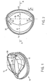
- the prosthetic mitral heart valve consists of a support housing 10 with two sails 11.
- the support housing 10 is by means of of a suture ring 23 sewn into the valve annulus in the patient's tissue.
- the support housing 10 consists of a thermoplastic such as Polyamide, which results in a slightly flexible body, for example made by injection molding and then with an outer coating made of polyurethane is.
- the one-piece support housing 10 has a base ring 12 on whose inner edges towards the outside in according to the state of the Technology are known rounded. For better attachment of the seam ring 23, the base ring on the outer casing Show bead.
- the essentially to the base ring footprint vertical wall is divided into a first wall 13 less curvature and a second wall 14 with larger Curvature on that together in plan view of the base base looks at two half forms with a common one Form longitudinal axis 15.
- the half transverse axes are accordingly 16 and 17 of different lengths, preferably their aspect ratio is 1: 2. Except for a possible bead in the base ring area the outer jacket of the walls 13 and 14 is curved, but smooth. The same applies with the exception of Post 18,19 described below for the Inner jacket of walls 13 and 14.
- the wall thickness of the walls 13 and 14 is different and minimizes to areas near the posts or is in the middle Area is greatest, preferably the wall thickness is in middle area between the posts twice as large as in the area near the post.
- the top face of the walls 13 and 14 to which the sail is attached is outward bevelled and runs essentially to the area of the Post in the form of a cut line resulting from a cut the respective half-shape with an oblique angle to it level.
- For gluing prefabricated sails is the line connecting the sails with the upper inner edge the walls 13 and 14 in a plane related to the Base ring base area at an angle of approx. 56 ° for the upper one Edge of the wall 13 or an angle of 41.5 ° for the upper edge the wall 14 runs.
- the face can also tangent to the plane that the sail in question closed state.
- the arrangement of the top Inner edge of the walls 13 and 14 in one each under one another angle employed level creates the advantage that cut both sails out of a flat plastic film can be and without tensile stress or without Danger of wrinkles on the upper edges of the walls can be glued into the areas near the posts.
- the material for the sails can be based on the state of the art Technology known plastic films, preferably made of thermoplastic Elastomers or plastic with elastomers Properties are used, preferably the Flexible polyurethane film sails.
- Posts 18 and 19 widen to their upper end faces 20 evenly.
- the posts are V-shaped executed and end in a wedge shape above the base ring base in the inlet area of the support housing 10.
- the longitudinal axis of the post 21 extends in relation to the base ring base area not vertically, but slightly compared to a surface normal inclined, for example at an angle of 65 °.
- a corresponding one The inclination of preferably 15 ° End face 20 of the post opposite the base ring base.
- the posts 18, 19 and their end faces 20 replace the given natural commissure sails and serve with their approximately equal-length triangular legs as an inner pad for the sails 11.
- Support housing is rounded.
- the sails 11 are on the Glued top edge of walls 13 and 14 to the support housing and are cut so that they close when closed the side isosceles and in the areas lying between the posts 18 and 19 approximately line up with the opposite sail.
- the commissure areas created by posts 18 and 19 prevent the sails from breaking through and serve together with the overlapping areas running along the longitudinal axis 15 the sail 11 to a sail support.
- the structure of the support housing 10 is the natural D or Kidney shape largely adapted, with the mural sail on the Top edge of the wall 13 at a steeper angle and the aortic sail on wall 14 under a flatter one Employment are arranged. This results in a lower one Height of the mitral heart valve, its main flow direction not coaxial, but inclined at about 15 ° to it.
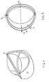
- FIG. 4 shows an alternative embodiment of a mitral heart valve, where the post described above no longer to appear physically. Rather are with this Embodiment the posts of equal thickness in the walls 23rd integrated. The walls run at opposite ends upwards to an end post end 24, the pointed or flattened as shown.
- the thickness of the wall d can decrease continuously from the base ring to the upper edge of the walls. 5, the thicknesses d of the walls 23, measured at the height of the base ring, are minimal in the area of the posts and increase to a maximum value.
- the thickness dimension d 1 is 2.57 mm
- the thickness dimension d 2 is 2.34 mm
- the thickness dimension d 3 is 1.4 mm.
- each manufactured sail by gluing or welding to the End faces of the support housing are attached.
- the heart valve according to the State of the art injection molding technology including the To produce 2-component injection molding, in which the Support housing manufactured and then the sails through Injection molding can be attached.
- Another option is the application of the so-called diving technique.
- the invention also extends to artificial blood pumps (Artificial hearts), conduit valve implants, bioprostheses or mechanical prostheses and the like, in which the support housing an integral part of a tubular housing or Hose is.
Landscapes
- Health & Medical Sciences (AREA)
- Engineering & Computer Science (AREA)
- Biomedical Technology (AREA)
- Cardiology (AREA)
- Oral & Maxillofacial Surgery (AREA)
- Transplantation (AREA)
- Heart & Thoracic Surgery (AREA)
- Vascular Medicine (AREA)
- Life Sciences & Earth Sciences (AREA)
- Animal Behavior & Ethology (AREA)
- General Health & Medical Sciences (AREA)
- Public Health (AREA)
- Veterinary Medicine (AREA)
- Prostheses (AREA)
- External Artificial Organs (AREA)
Description
- Fig. 1
- eine perspektivische Ansicht einer prothetischen Mitral-Herzklappe,
- Fig. 2
- eine Draufsicht auf die Herzklappe nach Fig. 1,
- Fig. 3
- einen Schnitt entlang der Linie A-A,
- Fig. 4
- eine perspektivische Ansicht einer weiteren prothetischen Mitral-Herzklappe und
- Fig. 5
- eine Draufsicht auf die Herzklappe nach Fig. 4.
Claims (9)
- Prothetische Mitral-Herzklappe, bestehend aus einem Stützgehäuse (Stent) (10) mit einem Basisring (12), der zwei im wesentlichen in Ringachsrichtung weisende, über bogenförmige, der Befestigung zweier flexibler Segel (11) dienende Wandungen (13,14) verbundene Pfosten (18,19) trägt, deren freie Enden eine Innenauflage für das Segel (11) bilden,
dadurch gekennzeichnet, daß der Basisring (12) - in Draufsicht betrachtet - als eine geschlossene unrunde Form aus zwei Halbformen mit unterschiedlicher Krümmung ausgebildet ist, die an zwei Übergangsstellen ineinander übergehen und einer gemeinsamen Längsachse (15), die durch die Übergangsstellen geht und zwei ungleich große halbe Querachsen (16,17), wobei die Pfosten (18,19) auf der Längsachse (15) liegen und die Übergangsstelle von der einen zur anderen Halbform bilden und wobei die Wandung (13) mit geringerer Krümmung ein unter einem zur Basisring-Grundfläche stärker geneigten Winkel angeordnetes flächenkleineres oder murales Segel (11) trägt als die Wandung (14) mit größerer Krümmung. - Mitral-Herzklappe nach Anspruch 1, dadurch gekennzeichnet, daß die Segelneigung, die durch die Lage der Verbindungslinie des Segels (11) mit der oberen Innenkante der Wandung (13,14) bestimmt ist, zwischen 25° und 45° für das weniger geneigte oder aortale Segel und zwischen 40° und 65° für das stärker geneigte (murale) Segel, jeweils relativ zur Basisgrundfläche, beträgt und gleichzeitig das stärker geneigte Segel um mindestens 5° stärker geneigt ist als das weniger geneigte Segel, so daß die Hauptströmungsrichtung um 10° bis 25°, vorzugsweise um 15° von der Normalen zum muralen Segel geneigt ist.
- Mitral-Herzklappe nach einem der Ansprüche 1 bis 2, dadurch gekennzeichnet, daß die Längen der halben Querachsen (16,17) in einem Verhältnis von 1,5 bis 2,5 : 1 stehen und/oder daß die gemeinsame Längsachse (15) eine Länge zwischen 10 mm und 45 mm aufweist.
- Mitral-Herzklappe nach einem der Ansprüche 1 bis 3, dadurch gekennzeichnet, daß die Pfosten dickengleich in die Wandungen (23) integriert sind, wobei das stirnseitige Pfostenende (24) spitz oder abgeflacht ausläuft.
- Mitral-Herzklappe nach einem der Ansprüche 1 bis 4, dadurch gekennzeichnet, daß die Wandungsdicke (d) vom Basisring zur oberen Kante der Wandungen abnimmt, vorzugsweise kontinuierlich abnimmt.
- Mitral-Herzklappe nach einem der Ansprüche 1 bis 5, dadurch gekennzeichnet, daß die Pfosten (18,19) sich zu ihrem freien Ende zum Stirnflächenmaß verdicken, vorzugsweise kontinuierlich, wobei die Pfosten (18,19) sich zur Basisgrundfläche hin und vor dieser endend keilförmig verjüngen.
- Mitral-Herzklappe nach einem der Ansprüche 1 bis 6, dadurch gekennzeichnet, daß die Dicke der Wandungen (13,14) des Basisringes (12) im Bereich zwischen den Pfosten (18,19), d.h. an der Segelbasis, größer ist als im pfostennahen Bereich, vorzugsweise um einen Faktor 1,4 bis 2,3.
- Mitral-Herzklappe nach einem der Ansprüche 1 bis 7, dadurch gekennzeichnet, daß die Verbindungslinie der Segel (11) mit der oberen Innenkante der Wandungen (13,14) jeweils in einer Ebene liegt.
- Mitral-Herzklappe nach Anspruch 2, dadurch gekennzeichnet, daß die Pfostenlängsachse (21) in Richtung der Hauptströmungsrichtung verläuft.
Applications Claiming Priority (3)
| Application Number | Priority Date | Filing Date | Title |
|---|---|---|---|
| DE19625202 | 1996-06-24 | ||
| DE19625202A DE19625202A1 (de) | 1996-06-24 | 1996-06-24 | Prothetische Mitral-Herzklappe |
| PCT/DE1997/001297 WO1997049355A1 (de) | 1996-06-24 | 1997-06-18 | Prothetische mitral-herzklappe |
Publications (2)
| Publication Number | Publication Date |
|---|---|
| EP0910313A1 EP0910313A1 (de) | 1999-04-28 |
| EP0910313B1 true EP0910313B1 (de) | 2003-11-05 |
Family
ID=7797831
Family Applications (1)
| Application Number | Title | Priority Date | Filing Date |
|---|---|---|---|
| EP97931640A Expired - Lifetime EP0910313B1 (de) | 1996-06-24 | 1997-06-18 | Prothetische mitral-herzklappe |
Country Status (10)
| Country | Link |
|---|---|
| US (1) | US6086612A (de) |
| EP (1) | EP0910313B1 (de) |
| JP (1) | JP2000513248A (de) |
| CN (1) | CN1143659C (de) |
| AT (1) | ATE253336T1 (de) |
| BR (1) | BR9709967A (de) |
| CA (1) | CA2258967A1 (de) |
| DE (2) | DE19625202A1 (de) |
| ES (1) | ES2208924T3 (de) |
| WO (1) | WO1997049355A1 (de) |
Cited By (3)
| Publication number | Priority date | Publication date | Assignee | Title |
|---|---|---|---|---|
| US10835375B2 (en) | 2014-06-12 | 2020-11-17 | Caisson Interventional, LLC | Two stage anchor and mitral valve assembly |
| US11439506B2 (en) | 2014-10-23 | 2022-09-13 | Caisson Interventional Llc | Systems and methods for heart valve therapy |
| US11833035B2 (en) | 2013-10-23 | 2023-12-05 | Caisson Interventional Llc | Methods and systems for heart valve therapy |
Families Citing this family (139)
| Publication number | Priority date | Publication date | Assignee | Title |
|---|---|---|---|---|
| GB9701479D0 (en) * | 1997-01-24 | 1997-03-12 | Aortech Europ Ltd | Heart valve |
| US6666885B2 (en) | 1999-04-16 | 2003-12-23 | Carbomedics Inc. | Heart valve leaflet |
| US6283994B1 (en) * | 1999-04-16 | 2001-09-04 | Sulzer Carbomedics Inc. | Heart valve leaflet |
| US6626899B2 (en) | 1999-06-25 | 2003-09-30 | Nidus Medical, Llc | Apparatus and methods for treating tissue |
| US20050055082A1 (en) | 2001-10-04 | 2005-03-10 | Shmuel Ben Muvhar | Flow reducing implant |
| DE10046550A1 (de) | 2000-09-19 | 2002-03-28 | Adiam Life Science Ag | Prothetische Mitral-Herzklappe |
| DE10050092A1 (de) | 2000-10-09 | 2002-04-11 | Adiam Life Science Ag | Herzklappenprothese, bestehend aus einem Stützgehäuse mit mindestens zwei Segeln, insbesondere Mitral-Herzklappe und Verfahren zu deren Herstellung |
| GB2371988B (en) * | 2001-02-08 | 2002-12-24 | Tayside Flow Technologies Ltd | Valve |
| US7556646B2 (en) | 2001-09-13 | 2009-07-07 | Edwards Lifesciences Corporation | Methods and apparatuses for deploying minimally-invasive heart valves |
| AU2002362442B2 (en) * | 2001-10-01 | 2008-08-07 | Ample Medical, Inc. | Methods and devices for heart valve treatments |
| DE10237787A1 (de) * | 2002-08-17 | 2004-03-04 | Robert Bosch Gmbh | Schichtsystem mit einer Siliziumschicht und einer Passivierschicht, Verfahren zur Erzeugung einer Passivierschicht auf einer Siliziumschicht und deren Verwendung |
| ES2311148T3 (es) * | 2003-03-20 | 2009-02-01 | Aortech International Plc | Valvula. |
| NZ527025A (en) | 2003-07-16 | 2007-01-26 | David Peter Shaw | Prosthetic valves for medical application |
| DE10340265A1 (de) * | 2003-08-29 | 2005-04-07 | Sievers, Hans-Hinrich, Prof. Dr.med. | Prothese zum Ersatz der Aorten- und/oder Mitralklappe des Herzens |
| IL158960A0 (en) | 2003-11-19 | 2004-05-12 | Neovasc Medical Ltd | Vascular implant |
| US20050149181A1 (en) * | 2004-01-07 | 2005-07-07 | Medtronic, Inc. | Bileaflet prosthetic valve and method of manufacture |
| US7871435B2 (en) | 2004-01-23 | 2011-01-18 | Edwards Lifesciences Corporation | Anatomically approximate prosthetic mitral heart valve |
| US7976539B2 (en) | 2004-03-05 | 2011-07-12 | Hansen Medical, Inc. | System and method for denaturing and fixing collagenous tissue |
| EP3603576B1 (de) | 2004-03-11 | 2021-01-20 | Percutaneous Cardiovascular Solutions Pty Limited | Perkutane herzklappenprothese |
| US8012201B2 (en) * | 2004-05-05 | 2011-09-06 | Direct Flow Medical, Inc. | Translumenally implantable heart valve with multiple chamber formed in place support |
| CA2848445C (en) | 2004-09-14 | 2016-10-25 | Edwards Lifesciences Ag | Device and method for treatment of heart valve regurgitation |
| US7744642B2 (en) * | 2004-11-19 | 2010-06-29 | Biomedical Research Associates, Inc. | Prosthetic venous valves |
| US7776084B2 (en) * | 2005-07-13 | 2010-08-17 | Edwards Lifesciences Corporation | Prosthetic mitral heart valve having a contoured sewing ring |
| US7455689B2 (en) * | 2005-08-25 | 2008-11-25 | Edwards Lifesciences Corporation | Four-leaflet stented mitral heart valve |
| AU2006315812B2 (en) | 2005-11-10 | 2013-03-28 | Cardiaq Valve Technologies, Inc. | Balloon-expandable, self-expanding, vascular prosthesis connecting stent |
| US7632308B2 (en) | 2005-11-23 | 2009-12-15 | Didier Loulmet | Methods, devices, and kits for treating mitral valve prolapse |
| WO2008013915A2 (en) | 2006-07-28 | 2008-01-31 | Arshad Quadri | Percutaneous valve prosthesis and system and method for implanting same |
| US7530369B2 (en) * | 2006-09-19 | 2009-05-12 | Anderson Lance E | One-way elastomer valve |
| EP2111190B1 (de) | 2007-01-19 | 2013-10-09 | Medtronic, Inc. | Gestentete Herzklappenvorrichtungen für atrioventrikulären Klappenersatz |
| EP2190379B1 (de) | 2007-08-23 | 2016-06-15 | Direct Flow Medical, Inc. | Transluminale implantierbare herzklappe mit geformter stütze |
| DE102007043830A1 (de) * | 2007-09-13 | 2009-04-02 | Lozonschi, Lucian, Madison | Herzklappenstent |
| US20090276040A1 (en) | 2008-05-01 | 2009-11-05 | Edwards Lifesciences Corporation | Device and method for replacing mitral valve |
| CA2749026C (en) | 2008-09-29 | 2018-01-09 | Impala, Inc. | Heart valve |
| EP2341871B1 (de) | 2008-10-01 | 2017-03-22 | Edwards Lifesciences CardiAQ LLC | Abgabesystem für ein gefässimplantat |
| AU2009302904B2 (en) * | 2008-10-10 | 2016-03-03 | Medicaltree Patent Ltd | An improved artificial valve |
| EP4321134A3 (de) | 2008-11-21 | 2024-05-01 | Percutaneous Cardiovascular Solutions Pty Limited | Herzklappenprothese und verfahren |
| JP5392539B2 (ja) * | 2008-12-25 | 2014-01-22 | 学校法人早稲田大学 | ステントレス人工僧帽弁及び人工弁葉 |
| US20100217371A1 (en) * | 2009-02-26 | 2010-08-26 | Medtronic Vascular, Inc. | Device, System, and Method for Aiding Stent Valve Deployment |
| AU2010236288A1 (en) | 2009-04-15 | 2011-10-20 | Cardiaq Valve Technologies, Inc. | Vascular implant and delivery system |
| NZ624106A (en) | 2009-04-29 | 2015-12-24 | Cleveland Clinic Foundation | Apparatus and method for replacing a diseased cardiac valve |
| US8652203B2 (en) | 2010-09-23 | 2014-02-18 | Cardiaq Valve Technologies, Inc. | Replacement heart valves, delivery devices and methods |
| US9730790B2 (en) | 2009-09-29 | 2017-08-15 | Edwards Lifesciences Cardiaq Llc | Replacement valve and method |
| US8449599B2 (en) | 2009-12-04 | 2013-05-28 | Edwards Lifesciences Corporation | Prosthetic valve for replacing mitral valve |
| US8579964B2 (en) | 2010-05-05 | 2013-11-12 | Neovasc Inc. | Transcatheter mitral valve prosthesis |
| US9603708B2 (en) | 2010-05-19 | 2017-03-28 | Dfm, Llc | Low crossing profile delivery catheter for cardiovascular prosthetic implant |
| CA2803149C (en) | 2010-06-21 | 2018-08-14 | Impala, Inc. | Replacement heart valve |
| US8845717B2 (en) | 2011-01-28 | 2014-09-30 | Middle Park Medical, Inc. | Coaptation enhancement implant, system, and method |
| US8888843B2 (en) | 2011-01-28 | 2014-11-18 | Middle Peak Medical, Inc. | Device, system, and method for transcatheter treatment of valve regurgitation |
| US9554897B2 (en) | 2011-04-28 | 2017-01-31 | Neovasc Tiara Inc. | Methods and apparatus for engaging a valve prosthesis with tissue |
| US9308087B2 (en) | 2011-04-28 | 2016-04-12 | Neovasc Tiara Inc. | Sequentially deployed transcatheter mitral valve prosthesis |
| US12502276B2 (en) | 2011-05-16 | 2025-12-23 | Edwards Lifesciences Corporation | Inversion delivery device and method for a prosthesis |
| US9427315B2 (en) | 2012-04-19 | 2016-08-30 | Caisson Interventional, LLC | Valve replacement systems and methods |
| US9011515B2 (en) | 2012-04-19 | 2015-04-21 | Caisson Interventional, LLC | Heart valve assembly systems and methods |
| US9445897B2 (en) | 2012-05-01 | 2016-09-20 | Direct Flow Medical, Inc. | Prosthetic implant delivery device with introducer catheter |
| US9345573B2 (en) | 2012-05-30 | 2016-05-24 | Neovasc Tiara Inc. | Methods and apparatus for loading a prosthesis onto a delivery system |
| US9283072B2 (en) | 2012-07-25 | 2016-03-15 | W. L. Gore & Associates, Inc. | Everting transcatheter valve and methods |
| US10376360B2 (en) | 2012-07-27 | 2019-08-13 | W. L. Gore & Associates, Inc. | Multi-frame prosthetic valve apparatus and methods |
| US9101469B2 (en) | 2012-12-19 | 2015-08-11 | W. L. Gore & Associates, Inc. | Prosthetic heart valve with leaflet shelving |
| US10039638B2 (en) | 2012-12-19 | 2018-08-07 | W. L. Gore & Associates, Inc. | Geometric prosthetic heart valves |
| US9144492B2 (en) | 2012-12-19 | 2015-09-29 | W. L. Gore & Associates, Inc. | Truncated leaflet for prosthetic heart valves, preformed valve |
| US9737398B2 (en) | 2012-12-19 | 2017-08-22 | W. L. Gore & Associates, Inc. | Prosthetic valves, frames and leaflets and methods thereof |
| US10321986B2 (en) | 2012-12-19 | 2019-06-18 | W. L. Gore & Associates, Inc. | Multi-frame prosthetic heart valve |
| US10966820B2 (en) | 2012-12-19 | 2021-04-06 | W. L. Gore & Associates, Inc. | Geometric control of bending character in prosthetic heart valve leaflets |
| US9968443B2 (en) | 2012-12-19 | 2018-05-15 | W. L. Gore & Associates, Inc. | Vertical coaptation zone in a planar portion of prosthetic heart valve leaflet |
| US9439763B2 (en) | 2013-02-04 | 2016-09-13 | Edwards Lifesciences Corporation | Prosthetic valve for replacing mitral valve |
| US10583002B2 (en) | 2013-03-11 | 2020-03-10 | Neovasc Tiara Inc. | Prosthetic valve with anti-pivoting mechanism |
| US20140277427A1 (en) | 2013-03-14 | 2014-09-18 | Cardiaq Valve Technologies, Inc. | Prosthesis for atraumatically grasping intralumenal tissue and methods of delivery |
| US9730791B2 (en) | 2013-03-14 | 2017-08-15 | Edwards Lifesciences Cardiaq Llc | Prosthesis for atraumatically grasping intralumenal tissue and methods of delivery |
| US9681951B2 (en) | 2013-03-14 | 2017-06-20 | Edwards Lifesciences Cardiaq Llc | Prosthesis with outer skirt and anchors |
| US9572665B2 (en) | 2013-04-04 | 2017-02-21 | Neovasc Tiara Inc. | Methods and apparatus for delivering a prosthetic valve to a beating heart |
| EP3016595B1 (de) | 2013-07-26 | 2018-12-19 | Edwards Lifesciences CardiAQ LLC | Systeme zum verschliessen von öffnungen in einer anatomischen wand |
| US10166098B2 (en) | 2013-10-25 | 2019-01-01 | Middle Peak Medical, Inc. | Systems and methods for transcatheter treatment of valve regurgitation |
| US9504565B2 (en) | 2013-12-06 | 2016-11-29 | W. L. Gore & Associates, Inc. | Asymmetric opening and closing prosthetic valve leaflet |
| EP3107497B1 (de) | 2014-02-21 | 2020-07-22 | Edwards Lifesciences CardiAQ LLC | Abgabevorrichtung für kontrollierten einsatz eines ersatzventils |
| USD755384S1 (en) | 2014-03-05 | 2016-05-03 | Edwards Lifesciences Cardiaq Llc | Stent |
| CA2948179C (en) | 2014-05-07 | 2023-08-15 | Baylor College Of Medicine | Artificial, flexible valves and methods of fabricating and serially expanding the same |
| CA3161000A1 (en) | 2014-05-19 | 2015-11-26 | Edwards Lifesciences Cardiaq Llc | Replacement mitral valve with annular flap |
| US9532870B2 (en) | 2014-06-06 | 2017-01-03 | Edwards Lifesciences Corporation | Prosthetic valve for replacing a mitral valve |
| CA2958061A1 (en) | 2014-06-18 | 2015-12-23 | Middle Peak Medical, Inc. | Mitral valve implants for the treatment of valvular regurgitation |
| US10251635B2 (en) | 2014-06-24 | 2019-04-09 | Middle Peak Medical, Inc. | Systems and methods for anchoring an implant |
| JP6445683B2 (ja) | 2014-08-18 | 2018-12-26 | ダブリュ.エル.ゴア アンド アソシエイツ,インコーポレイティドW.L. Gore & Associates, Incorporated | 人工弁のための一体型縫合カフを有するフレーム |
| US9827094B2 (en) * | 2014-09-15 | 2017-11-28 | W. L. Gore & Associates, Inc. | Prosthetic heart valve with retention elements |
| CA2962747C (en) | 2014-09-28 | 2023-02-28 | Cardiokinetix, Inc. | Apparatuses for treating cardiac dysfunction |
| US10507101B2 (en) * | 2014-10-13 | 2019-12-17 | W. L. Gore & Associates, Inc. | Valved conduit |
| US9750605B2 (en) | 2014-10-23 | 2017-09-05 | Caisson Interventional, LLC | Systems and methods for heart valve therapy |
| US10531951B2 (en) | 2014-11-26 | 2020-01-14 | Edwards Lifesciences Corporation | Transcatheter prosthetic heart valve and delivery system |
| US9937037B2 (en) | 2014-12-18 | 2018-04-10 | W. L. Gore & Associates, Inc. | Prosthetic valved conduits with mechanically coupled leaflets |
| US10751064B2 (en) | 2015-03-20 | 2020-08-25 | Edwards Lifescience Corporation | Systems and methods for delivering an implantable device |
| US10441416B2 (en) | 2015-04-21 | 2019-10-15 | Edwards Lifesciences Corporation | Percutaneous mitral valve replacement device |
| US10376363B2 (en) | 2015-04-30 | 2019-08-13 | Edwards Lifesciences Cardiaq Llc | Replacement mitral valve, delivery system for replacement mitral valve and methods of use |
| US10226335B2 (en) | 2015-06-22 | 2019-03-12 | Edwards Lifesciences Cardiaq Llc | Actively controllable heart valve implant and method of controlling same |
| US10092400B2 (en) | 2015-06-23 | 2018-10-09 | Edwards Lifesciences Cardiaq Llc | Systems and methods for anchoring and sealing a prosthetic heart valve |
| US10575951B2 (en) | 2015-08-26 | 2020-03-03 | Edwards Lifesciences Cardiaq Llc | Delivery device and methods of use for transapical delivery of replacement mitral valve |
| US10117744B2 (en) | 2015-08-26 | 2018-11-06 | Edwards Lifesciences Cardiaq Llc | Replacement heart valves and methods of delivery |
| US10350066B2 (en) | 2015-08-28 | 2019-07-16 | Edwards Lifesciences Cardiaq Llc | Steerable delivery system for replacement mitral valve and methods of use |
| US9592121B1 (en) | 2015-11-06 | 2017-03-14 | Middle Peak Medical, Inc. | Device, system, and method for transcatheter treatment of valvular regurgitation |
| AU2016380345B2 (en) | 2015-12-30 | 2021-10-28 | Caisson Interventional, LLC | Systems and methods for heart valve therapy |
| USD815744S1 (en) | 2016-04-28 | 2018-04-17 | Edwards Lifesciences Cardiaq Llc | Valve frame for a delivery system |
| US10350062B2 (en) | 2016-07-21 | 2019-07-16 | Edwards Lifesciences Corporation | Replacement heart valve prosthesis |
| CN109789017B (zh) | 2016-08-19 | 2022-05-31 | 爱德华兹生命科学公司 | 用于置换二尖瓣的可转向递送系统和使用方法 |
| CN109843219B (zh) | 2016-08-26 | 2022-04-05 | 爱德华兹生命科学公司 | 多部分置换心脏瓣膜假体 |
| US10758348B2 (en) | 2016-11-02 | 2020-09-01 | Edwards Lifesciences Corporation | Supra and sub-annular mitral valve delivery system |
| JP7159230B2 (ja) | 2017-03-13 | 2022-10-24 | ポラレス・メディカル・インコーポレイテッド | 弁逆流の経カテーテル治療のためのデバイス、システム、および方法 |
| US10653524B2 (en) | 2017-03-13 | 2020-05-19 | Polares Medical Inc. | Device, system, and method for transcatheter treatment of valvular regurgitation |
| US10478303B2 (en) | 2017-03-13 | 2019-11-19 | Polares Medical Inc. | Device, system, and method for transcatheter treatment of valvular regurgitation |
| US11406533B2 (en) | 2017-03-17 | 2022-08-09 | W. L. Gore & Associates, Inc. | Integrated aqueous shunt for glaucoma treatment |
| WO2019010321A1 (en) | 2017-07-06 | 2019-01-10 | Edwards Lifesciences Corporation | Steerable rail delivery system |
| WO2019055577A1 (en) | 2017-09-12 | 2019-03-21 | W. L. Gore & Associates, Inc. | SHEET FRAME FIXATION FOR PROSTHETIC VALVES |
| US11020221B2 (en) | 2017-09-27 | 2021-06-01 | W. L. Gore & Associates, Inc. | Prosthetic valve with expandable frame and associated systems and methods |
| JP6875601B2 (ja) | 2017-09-27 | 2021-05-26 | ダブリュ.エル.ゴア アンド アソシエイツ,インコーポレイティドW.L. Gore & Associates, Incorporated | リーフレットが機械的にカップリングされた人工弁 |
| AU2018347852B2 (en) | 2017-10-13 | 2021-08-19 | Edwards Lifesciences Corporation | Telescoping prosthetic valve and delivery system |
| US11039919B2 (en) | 2017-10-31 | 2021-06-22 | W. L. Gore & Associates, Inc. | Valved conduit |
| US11154397B2 (en) | 2017-10-31 | 2021-10-26 | W. L. Gore & Associates, Inc. | Jacket for surgical heart valve |
| EP3703618A1 (de) | 2017-10-31 | 2020-09-09 | W. L. Gore & Associates, Inc. | Herzklappenprothese |
| CN111526839B (zh) | 2017-10-31 | 2023-06-13 | W.L.戈尔及同仁股份有限公司 | 导管部署系统和相关联的方法 |
| WO2019089136A1 (en) | 2017-10-31 | 2019-05-09 | W. L. Gore & Associates, Inc. | Medical valve and leaflet promoting tissue ingrowth |
| CN117481869A (zh) | 2018-01-25 | 2024-02-02 | 爱德华兹生命科学公司 | 在部署后用于辅助置换瓣膜重新捕获和重新定位的递送系统 |
| US11051934B2 (en) | 2018-02-28 | 2021-07-06 | Edwards Lifesciences Corporation | Prosthetic mitral valve with improved anchors and seal |
| CA3110653A1 (en) | 2018-08-29 | 2020-03-05 | W. L. Gore & Associates, Inc. | Drug therapy delivery systems and methods |
| CN113693784B (zh) * | 2018-09-21 | 2024-01-16 | 上海纽脉医疗科技股份有限公司 | 心脏瓣膜支架 |
| USD977642S1 (en) | 2018-10-29 | 2023-02-07 | W. L. Gore & Associates, Inc. | Pulmonary valve conduit |
| USD926322S1 (en) | 2018-11-07 | 2021-07-27 | W. L. Gore & Associates, Inc. | Heart valve cover |
| US11678983B2 (en) | 2018-12-12 | 2023-06-20 | W. L. Gore & Associates, Inc. | Implantable component with socket |
| EP3914165B1 (de) | 2019-01-23 | 2024-08-14 | Shockwave Medical, Inc. | Abgedeckte strommodifizierungsvorrichtung |
| WO2020163031A1 (en) | 2019-02-04 | 2020-08-13 | Edwards Lifesciences Corporation | Guide wire apparatuses and methods |
| US11497601B2 (en) | 2019-03-01 | 2022-11-15 | W. L. Gore & Associates, Inc. | Telescoping prosthetic valve with retention element |
| CN121606417A (zh) | 2019-04-12 | 2026-03-06 | 爱德华兹生命科学公司 | 具有多部分式框架和相关联的弹性桥接特征的瓣膜 |
| ES2982566T3 (es) | 2019-04-23 | 2024-10-16 | Edwards Lifesciences Corp | Sistema de suministro de implantes motorizado |
| US11801131B2 (en) | 2019-12-20 | 2023-10-31 | Medtronic Vascular, Inc. | Elliptical heart valve prostheses, delivery systems, and methods of use |
| CN115209837A (zh) * | 2020-03-02 | 2022-10-18 | 百多力股份公司 | 心脏瓣膜假体 |
| CN111904661B (zh) * | 2020-06-04 | 2022-12-02 | 金仕生物科技(常熟)有限公司 | 一种二叶瓣瓣膜假体 |
| CN111991119B (zh) * | 2020-09-14 | 2022-10-21 | 金仕生物科技(常熟)有限公司 | 带瓣耳的二叶瓣瓣膜假体 |
| US11464634B2 (en) | 2020-12-16 | 2022-10-11 | Polares Medical Inc. | Device, system, and method for transcatheter treatment of valvular regurgitation with secondary anchors |
| EP4247297A1 (de) | 2020-12-18 | 2023-09-27 | Edwards Lifesciences Corporation | Lagerungsgefässanordnung für eine aprothetische herzklappe |
| US11759321B2 (en) | 2021-06-25 | 2023-09-19 | Polares Medical Inc. | Device, system, and method for transcatheter treatment of valvular regurgitation |
| AU2022377336A1 (en) | 2021-10-27 | 2024-04-11 | Edwards Lifesciences Corporation | System and method for crimping and loading a prosthetic heart valve |
| US12544262B2 (en) | 2021-11-05 | 2026-02-10 | W. L. Gore & Associates, Inc. | Fluid drainage devices, systems, and methods |
| US12527691B2 (en) | 2021-11-05 | 2026-01-20 | W. L. Gore & Associates, Inc. | Fluid drainage devices, systems, and methods |
| US12478474B2 (en) | 2023-05-04 | 2025-11-25 | Polares Medical Inc. | Device, system, and method with an adaptive leaflet |
Family Cites Families (16)
| Publication number | Priority date | Publication date | Assignee | Title |
|---|---|---|---|---|
| US4491986A (en) * | 1976-05-12 | 1985-01-08 | Shlomo Gabbay | Heart valve |
| GB1603634A (en) * | 1977-05-05 | 1981-11-25 | Nat Res Dev | Prosthetic valves |
| DE2742681C3 (de) | 1977-09-22 | 1980-07-31 | Dr. Eduard Fresenius, Chemisch- Pharmazeutische Industrie Kg, 6380 Bad Homburg | Prothetisches Verschlußelement zum Ersatz der Mitral- und Tricuspldalklappe im menschlichen Herzen |
| ES465824A1 (es) * | 1978-01-07 | 1978-11-01 | Ramos Martinez Wilson | Protesis metalica valvular cardiaca. |
| US4306319A (en) * | 1980-06-16 | 1981-12-22 | Robert L. Kaster | Heart valve with non-circular body |
| US4340977A (en) * | 1980-09-19 | 1982-07-27 | Brownlee Richard T | Catenary mitral valve replacement |
| FR2548888A1 (fr) * | 1983-06-21 | 1985-01-18 | Bex Jean Pierre | Valve cardiaque artificielle |
| CA1232407A (en) * | 1983-06-23 | 1988-02-09 | David K. Walker | Bubble heart valve |
| US4759758A (en) * | 1984-12-07 | 1988-07-26 | Shlomo Gabbay | Prosthetic heart valve |
| US5156621A (en) * | 1988-03-22 | 1992-10-20 | Navia Jose A | Stentless bioprosthetic cardiac valve |
| GB9012716D0 (en) * | 1990-06-07 | 1990-08-01 | Frater Robert W M | Mitral heart valve replacements |
| RU1767723C (ru) * | 1990-08-14 | 1995-01-27 | Кирово-Чепецкий химический комбинат | Протез клапана сердца |
| DE4222610A1 (de) * | 1992-07-10 | 1994-01-13 | Jansen Josef Dr Ing | Stützgehäuse für Klappen- und Schließorgane |
| US5772694A (en) * | 1995-05-16 | 1998-06-30 | Medical Carbon Research Institute L.L.C. | Prosthetic heart valve with improved blood flow |
| US6007577A (en) * | 1995-06-07 | 1999-12-28 | St. Jude Medical, Inc. | Prosthetic heart valve with increased valve lumen |
| US5800421A (en) * | 1996-06-12 | 1998-09-01 | Lemelson; Jerome H. | Medical devices using electrosensitive gels |
-
1996
- 1996-06-24 DE DE19625202A patent/DE19625202A1/de not_active Withdrawn
-
1997
- 1997-06-18 AT AT97931640T patent/ATE253336T1/de not_active IP Right Cessation
- 1997-06-18 US US09/194,045 patent/US6086612A/en not_active Expired - Fee Related
- 1997-06-18 CN CNB971958092A patent/CN1143659C/zh not_active Expired - Fee Related
- 1997-06-18 ES ES97931640T patent/ES2208924T3/es not_active Expired - Lifetime
- 1997-06-18 WO PCT/DE1997/001297 patent/WO1997049355A1/de not_active Ceased
- 1997-06-18 DE DE59710965T patent/DE59710965D1/de not_active Expired - Fee Related
- 1997-06-18 JP JP10502101A patent/JP2000513248A/ja not_active Ceased
- 1997-06-18 BR BR9709967-8A patent/BR9709967A/pt not_active IP Right Cessation
- 1997-06-18 EP EP97931640A patent/EP0910313B1/de not_active Expired - Lifetime
- 1997-06-18 CA CA002258967A patent/CA2258967A1/en not_active Abandoned
Cited By (4)
| Publication number | Priority date | Publication date | Assignee | Title |
|---|---|---|---|---|
| US11833035B2 (en) | 2013-10-23 | 2023-12-05 | Caisson Interventional Llc | Methods and systems for heart valve therapy |
| US10835375B2 (en) | 2014-06-12 | 2020-11-17 | Caisson Interventional, LLC | Two stage anchor and mitral valve assembly |
| US12491068B2 (en) | 2014-06-12 | 2025-12-09 | Caisson Interventional Llc | Two stage anchor and mitral valve assembly |
| US11439506B2 (en) | 2014-10-23 | 2022-09-13 | Caisson Interventional Llc | Systems and methods for heart valve therapy |
Also Published As
| Publication number | Publication date |
|---|---|
| DE59710965D1 (de) | 2003-12-11 |
| CN1143659C (zh) | 2004-03-31 |
| CN1223562A (zh) | 1999-07-21 |
| ES2208924T3 (es) | 2004-06-16 |
| CA2258967A1 (en) | 1997-12-31 |
| ATE253336T1 (de) | 2003-11-15 |
| US6086612A (en) | 2000-07-11 |
| BR9709967A (pt) | 2000-02-15 |
| EP0910313A1 (de) | 1999-04-28 |
| DE19625202A1 (de) | 1998-01-02 |
| WO1997049355A1 (de) | 1997-12-31 |
| JP2000513248A (ja) | 2000-10-10 |
Similar Documents
| Publication | Publication Date | Title |
|---|---|---|
| EP0910313B1 (de) | Prothetische mitral-herzklappe | |
| EP0910314B1 (de) | Prothetische herzklappe | |
| EP1318774B1 (de) | Prothetische mitral-herzklappe | |
| EP0649295B1 (de) | Stützgehäuse für klappen- und schliessorgane, insbesondere, für herzklappenprothesen | |
| DE69215960T2 (de) | Herzklappenprothese, insbesondere zum Ersatz der Aortenklappe | |
| DE69924271T2 (de) | Ventilklappen aus kunststoff mit geformten freien rändern | |
| EP0277527B1 (de) | Herzklappenprothese | |
| DE2819089C2 (de) | ||
| EP0143246B1 (de) | Herzklappenprothese | |
| DE69930500T2 (de) | Herzklappenprothese | |
| EP0277528B1 (de) | Herzklappenprothese | |
| DE1931428C3 (de) | Brustprothese | |
| DE102011107551B4 (de) | Anuloplastiering | |
| DE2056798A1 (de) | Künstliche Herzklappe | |
| EP0182090A2 (de) | Herzklappenprothese | |
| DE1932817A1 (de) | Rueckflussverhinderndes Ventil | |
| DE2309933A1 (de) | Mikrokontaktlinse | |
| EP0275951A1 (de) | Herzklappenprothese | |
| DE3853081T2 (de) | Herzklappenprothese. | |
| EP0910312B1 (de) | Prothetische herzklappe | |
| WO1998002115A1 (de) | Herzklappenprothese | |
| EP0536598B1 (de) | Prothese zur Verwendung bei Potenzstörungen | |
| DE102020113585A1 (de) | Anordnung für eine in die obere oder die untere Hohlvene eines menschlichen Körpers minimal-invasiv implantierbare Verschlusseinrichtung und minimal-invasiv implantierbare Trikuspidalklappen-Prothese | |
| DE6924634U (de) | Brustprothese | |
| DE9415431U1 (de) | Herzklappenprothese |
Legal Events
| Date | Code | Title | Description |
|---|---|---|---|
| PUAI | Public reference made under article 153(3) epc to a published international application that has entered the european phase |
Free format text: ORIGINAL CODE: 0009012 |
|
| 17P | Request for examination filed |
Effective date: 19981126 |
|
| AK | Designated contracting states |
Kind code of ref document: A1 Designated state(s): AT BE CH DE ES FR GB IT LI NL SE |
|
| RAP1 | Party data changed (applicant data changed or rights of an application transferred) |
Owner name: ADIAM LIFE SCIENCE AG |
|
| GRAH | Despatch of communication of intention to grant a patent |
Free format text: ORIGINAL CODE: EPIDOS IGRA |
|
| GRAS | Grant fee paid |
Free format text: ORIGINAL CODE: EPIDOSNIGR3 |
|
| GRAA | (expected) grant |
Free format text: ORIGINAL CODE: 0009210 |
|
| AK | Designated contracting states |
Kind code of ref document: B1 Designated state(s): AT BE CH DE ES FR GB IT LI NL SE |
|
| REG | Reference to a national code |
Ref country code: GB Ref legal event code: FG4D Free format text: NOT ENGLISH |
|
| REG | Reference to a national code |
Ref country code: CH Ref legal event code: NV Representative=s name: ISLER & PEDRAZZINI AG Ref country code: CH Ref legal event code: EP |
|
| REF | Corresponds to: |
Ref document number: 59710965 Country of ref document: DE Date of ref document: 20031211 Kind code of ref document: P |
|
| GBT | Gb: translation of ep patent filed (gb section 77(6)(a)/1977) |
Effective date: 20040115 |
|
| REG | Reference to a national code |
Ref country code: SE Ref legal event code: TRGR |
|
| PGFP | Annual fee paid to national office [announced via postgrant information from national office to epo] |
Ref country code: GB Payment date: 20040615 Year of fee payment: 8 |
|
| REG | Reference to a national code |
Ref country code: ES Ref legal event code: FG2A Ref document number: 2208924 Country of ref document: ES Kind code of ref document: T3 |
|
| PGFP | Annual fee paid to national office [announced via postgrant information from national office to epo] |
Ref country code: SE Payment date: 20040617 Year of fee payment: 8 |
|
| PGFP | Annual fee paid to national office [announced via postgrant information from national office to epo] |
Ref country code: AT Payment date: 20040618 Year of fee payment: 8 Ref country code: NL Payment date: 20040618 Year of fee payment: 8 Ref country code: FR Payment date: 20040618 Year of fee payment: 8 Ref country code: ES Payment date: 20040618 Year of fee payment: 8 |
|
| PGFP | Annual fee paid to national office [announced via postgrant information from national office to epo] |
Ref country code: CH Payment date: 20040628 Year of fee payment: 8 |
|
| PGFP | Annual fee paid to national office [announced via postgrant information from national office to epo] |
Ref country code: BE Payment date: 20040713 Year of fee payment: 8 |
|
| ET | Fr: translation filed | ||
| PGFP | Annual fee paid to national office [announced via postgrant information from national office to epo] |
Ref country code: DE Payment date: 20040825 Year of fee payment: 8 |
|
| PLBE | No opposition filed within time limit |
Free format text: ORIGINAL CODE: 0009261 |
|
| STAA | Information on the status of an ep patent application or granted ep patent |
Free format text: STATUS: NO OPPOSITION FILED WITHIN TIME LIMIT |
|
| 26N | No opposition filed |
Effective date: 20040806 |
|
| PG25 | Lapsed in a contracting state [announced via postgrant information from national office to epo] |
Ref country code: IT Free format text: LAPSE BECAUSE OF NON-PAYMENT OF DUE FEES;WARNING: LAPSES OF ITALIAN PATENTS WITH EFFECTIVE DATE BEFORE 2007 MAY HAVE OCCURRED AT ANY TIME BEFORE 2007. THE CORRECT EFFECTIVE DATE MAY BE DIFFERENT FROM THE ONE RECORDED. Effective date: 20050618 Ref country code: GB Free format text: LAPSE BECAUSE OF NON-PAYMENT OF DUE FEES Effective date: 20050618 Ref country code: AT Free format text: LAPSE BECAUSE OF NON-PAYMENT OF DUE FEES Effective date: 20050618 |
|
| PG25 | Lapsed in a contracting state [announced via postgrant information from national office to epo] |
Ref country code: SE Free format text: LAPSE BECAUSE OF NON-PAYMENT OF DUE FEES Effective date: 20050619 |
|
| PG25 | Lapsed in a contracting state [announced via postgrant information from national office to epo] |
Ref country code: ES Free format text: LAPSE BECAUSE OF NON-PAYMENT OF DUE FEES Effective date: 20050620 |
|
| PG25 | Lapsed in a contracting state [announced via postgrant information from national office to epo] |
Ref country code: LI Free format text: LAPSE BECAUSE OF NON-PAYMENT OF DUE FEES Effective date: 20050630 Ref country code: CH Free format text: LAPSE BECAUSE OF NON-PAYMENT OF DUE FEES Effective date: 20050630 Ref country code: BE Free format text: LAPSE BECAUSE OF NON-PAYMENT OF DUE FEES Effective date: 20050630 |
|
| PG25 | Lapsed in a contracting state [announced via postgrant information from national office to epo] |
Ref country code: NL Free format text: LAPSE BECAUSE OF NON-PAYMENT OF DUE FEES Effective date: 20060101 |
|
| PG25 | Lapsed in a contracting state [announced via postgrant information from national office to epo] |
Ref country code: DE Free format text: LAPSE BECAUSE OF NON-PAYMENT OF DUE FEES Effective date: 20060103 |
|
| REG | Reference to a national code |
Ref country code: CH Ref legal event code: PL |
|
| EUG | Se: european patent has lapsed | ||
| PG25 | Lapsed in a contracting state [announced via postgrant information from national office to epo] |
Ref country code: FR Free format text: LAPSE BECAUSE OF NON-PAYMENT OF DUE FEES Effective date: 20060228 |
|
| GBPC | Gb: european patent ceased through non-payment of renewal fee |
Effective date: 20050618 |
|
| NLV4 | Nl: lapsed or anulled due to non-payment of the annual fee |
Effective date: 20060101 |
|
| REG | Reference to a national code |
Ref country code: FR Ref legal event code: ST Effective date: 20060228 |
|
| REG | Reference to a national code |
Ref country code: ES Ref legal event code: FD2A Effective date: 20050620 |
|
| BERE | Be: lapsed |
Owner name: *ADIAM LIFE SCIENCE A.G. Effective date: 20050630 |