EP0910248B1 - Procede, dispositif et outil de decoupage pour la production de morceaux de pate individuels a partir d'une bande de pate continue - Google Patents
Procede, dispositif et outil de decoupage pour la production de morceaux de pate individuels a partir d'une bande de pate continue Download PDFInfo
- Publication number
- EP0910248B1 EP0910248B1 EP98912488A EP98912488A EP0910248B1 EP 0910248 B1 EP0910248 B1 EP 0910248B1 EP 98912488 A EP98912488 A EP 98912488A EP 98912488 A EP98912488 A EP 98912488A EP 0910248 B1 EP0910248 B1 EP 0910248B1
- Authority
- EP
- European Patent Office
- Prior art keywords
- dough
- cutting
- punch tool
- punch
- strip
- Prior art date
- Legal status (The legal status is an assumption and is not a legal conclusion. Google has not performed a legal analysis and makes no representation as to the accuracy of the status listed.)
- Expired - Lifetime
Links
- 238000005520 cutting process Methods 0.000 title claims description 140
- 238000000034 method Methods 0.000 title claims description 43
- 238000004080 punching Methods 0.000 claims description 88
- 230000033001 locomotion Effects 0.000 claims description 39
- 238000000151 deposition Methods 0.000 claims description 8
- 238000006073 displacement reaction Methods 0.000 claims description 8
- 238000004519 manufacturing process Methods 0.000 claims description 7
- 238000012545 processing Methods 0.000 claims description 7
- 230000001360 synchronised effect Effects 0.000 claims description 3
- 230000008878 coupling Effects 0.000 claims 1
- 238000010168 coupling process Methods 0.000 claims 1
- 238000005859 coupling reaction Methods 0.000 claims 1
- 239000000758 substrate Substances 0.000 claims 1
- 239000002699 waste material Substances 0.000 claims 1
- 230000008569 process Effects 0.000 description 12
- 238000003860 storage Methods 0.000 description 11
- 229920001971 elastomer Polymers 0.000 description 9
- 235000012830 plain croissants Nutrition 0.000 description 7
- 239000000806 elastomer Substances 0.000 description 6
- 239000002131 composite material Substances 0.000 description 4
- 239000004033 plastic Substances 0.000 description 4
- 229920003023 plastic Polymers 0.000 description 4
- 238000003892 spreading Methods 0.000 description 4
- 230000007480 spreading Effects 0.000 description 4
- 230000008901 benefit Effects 0.000 description 3
- 239000003292 glue Substances 0.000 description 3
- 238000012549 training Methods 0.000 description 3
- 238000004804 winding Methods 0.000 description 3
- 230000008859 change Effects 0.000 description 2
- 239000003795 chemical substances by application Substances 0.000 description 2
- 230000000295 complement effect Effects 0.000 description 2
- 238000013016 damping Methods 0.000 description 2
- 230000001960 triggered effect Effects 0.000 description 2
- 235000007688 Lycopersicon esculentum Nutrition 0.000 description 1
- 240000003768 Solanum lycopersicum Species 0.000 description 1
- 208000012886 Vertigo Diseases 0.000 description 1
- 230000009471 action Effects 0.000 description 1
- 235000015173 baked goods and baking mixes Nutrition 0.000 description 1
- 230000005540 biological transmission Effects 0.000 description 1
- 210000000078 claw Anatomy 0.000 description 1
- 238000004891 communication Methods 0.000 description 1
- 238000010276 construction Methods 0.000 description 1
- 239000002173 cutting fluid Substances 0.000 description 1
- 238000013461 design Methods 0.000 description 1
- 238000009826 distribution Methods 0.000 description 1
- 238000005516 engineering process Methods 0.000 description 1
- 230000000977 initiatory effect Effects 0.000 description 1
- 238000003780 insertion Methods 0.000 description 1
- 230000037431 insertion Effects 0.000 description 1
- 230000000149 penetrating effect Effects 0.000 description 1
- 230000035515 penetration Effects 0.000 description 1
- 230000010363 phase shift Effects 0.000 description 1
- 229920002635 polyurethane Polymers 0.000 description 1
- 239000004814 polyurethane Substances 0.000 description 1
- 230000009467 reduction Effects 0.000 description 1
- 230000001105 regulatory effect Effects 0.000 description 1
- 238000000926 separation method Methods 0.000 description 1
- 230000006641 stabilisation Effects 0.000 description 1
- 238000011105 stabilization Methods 0.000 description 1
Images
Classifications
-
- A—HUMAN NECESSITIES
- A21—BAKING; EDIBLE DOUGHS
- A21C—MACHINES OR EQUIPMENT FOR MAKING OR PROCESSING DOUGHS; HANDLING BAKED ARTICLES MADE FROM DOUGH
- A21C3/00—Machines or apparatus for shaping batches of dough before subdivision
- A21C3/06—Machines for coiling sheets of dough, e.g. for producing rolls
-
- A—HUMAN NECESSITIES
- A21—BAKING; EDIBLE DOUGHS
- A21C—MACHINES OR EQUIPMENT FOR MAKING OR PROCESSING DOUGHS; HANDLING BAKED ARTICLES MADE FROM DOUGH
- A21C11/00—Other machines for forming the dough into its final shape before cooking or baking
- A21C11/10—Other machines for forming the dough into its final shape before cooking or baking combined with cutting apparatus
-
- A—HUMAN NECESSITIES
- A21—BAKING; EDIBLE DOUGHS
- A21C—MACHINES OR EQUIPMENT FOR MAKING OR PROCESSING DOUGHS; HANDLING BAKED ARTICLES MADE FROM DOUGH
- A21C9/00—Other apparatus for handling dough or dough pieces
- A21C9/08—Depositing, arranging and conveying apparatus for handling pieces, e.g. sheets of dough
- A21C9/085—Separating, spacing, orienting or aligning discrete dough pieces, e.g. after passing a cutting device
-
- Y—GENERAL TAGGING OF NEW TECHNOLOGICAL DEVELOPMENTS; GENERAL TAGGING OF CROSS-SECTIONAL TECHNOLOGIES SPANNING OVER SEVERAL SECTIONS OF THE IPC; TECHNICAL SUBJECTS COVERED BY FORMER USPC CROSS-REFERENCE ART COLLECTIONS [XRACs] AND DIGESTS
- Y10—TECHNICAL SUBJECTS COVERED BY FORMER USPC
- Y10S—TECHNICAL SUBJECTS COVERED BY FORMER USPC CROSS-REFERENCE ART COLLECTIONS [XRACs] AND DIGESTS
- Y10S83/00—Cutting
- Y10S83/929—Particular nature of work or product
- Y10S83/932—Edible
-
- Y—GENERAL TAGGING OF NEW TECHNOLOGICAL DEVELOPMENTS; GENERAL TAGGING OF CROSS-SECTIONAL TECHNOLOGIES SPANNING OVER SEVERAL SECTIONS OF THE IPC; TECHNICAL SUBJECTS COVERED BY FORMER USPC CROSS-REFERENCE ART COLLECTIONS [XRACs] AND DIGESTS
- Y10—TECHNICAL SUBJECTS COVERED BY FORMER USPC
- Y10T—TECHNICAL SUBJECTS COVERED BY FORMER US CLASSIFICATION
- Y10T83/00—Cutting
- Y10T83/04—Processes
- Y10T83/0448—With subsequent handling [i.e., of product]
-
- Y—GENERAL TAGGING OF NEW TECHNOLOGICAL DEVELOPMENTS; GENERAL TAGGING OF CROSS-SECTIONAL TECHNOLOGIES SPANNING OVER SEVERAL SECTIONS OF THE IPC; TECHNICAL SUBJECTS COVERED BY FORMER USPC CROSS-REFERENCE ART COLLECTIONS [XRACs] AND DIGESTS
- Y10—TECHNICAL SUBJECTS COVERED BY FORMER USPC
- Y10T—TECHNICAL SUBJECTS COVERED BY FORMER US CLASSIFICATION
- Y10T83/00—Cutting
- Y10T83/04—Processes
- Y10T83/0505—With reorientation of work between cuts
- Y10T83/051—Relative to same tool
-
- Y—GENERAL TAGGING OF NEW TECHNOLOGICAL DEVELOPMENTS; GENERAL TAGGING OF CROSS-SECTIONAL TECHNOLOGIES SPANNING OVER SEVERAL SECTIONS OF THE IPC; TECHNICAL SUBJECTS COVERED BY FORMER USPC CROSS-REFERENCE ART COLLECTIONS [XRACs] AND DIGESTS
- Y10—TECHNICAL SUBJECTS COVERED BY FORMER USPC
- Y10T—TECHNICAL SUBJECTS COVERED BY FORMER US CLASSIFICATION
- Y10T83/00—Cutting
- Y10T83/162—With control means responsive to replaceable or selectable information program
-
- Y—GENERAL TAGGING OF NEW TECHNOLOGICAL DEVELOPMENTS; GENERAL TAGGING OF CROSS-SECTIONAL TECHNOLOGIES SPANNING OVER SEVERAL SECTIONS OF THE IPC; TECHNICAL SUBJECTS COVERED BY FORMER USPC CROSS-REFERENCE ART COLLECTIONS [XRACs] AND DIGESTS
- Y10—TECHNICAL SUBJECTS COVERED BY FORMER USPC
- Y10T—TECHNICAL SUBJECTS COVERED BY FORMER US CLASSIFICATION
- Y10T83/00—Cutting
- Y10T83/202—With product handling means
- Y10T83/2074—Including means to divert one portion of product from another
-
- Y—GENERAL TAGGING OF NEW TECHNOLOGICAL DEVELOPMENTS; GENERAL TAGGING OF CROSS-SECTIONAL TECHNOLOGIES SPANNING OVER SEVERAL SECTIONS OF THE IPC; TECHNICAL SUBJECTS COVERED BY FORMER USPC CROSS-REFERENCE ART COLLECTIONS [XRACs] AND DIGESTS
- Y10—TECHNICAL SUBJECTS COVERED BY FORMER USPC
- Y10T—TECHNICAL SUBJECTS COVERED BY FORMER US CLASSIFICATION
- Y10T83/00—Cutting
- Y10T83/202—With product handling means
- Y10T83/2092—Means to move, guide, or permit free fall or flight of product
- Y10T83/2192—Endless conveyor
- Y10T83/2194—And means to remove product therefrom
-
- Y—GENERAL TAGGING OF NEW TECHNOLOGICAL DEVELOPMENTS; GENERAL TAGGING OF CROSS-SECTIONAL TECHNOLOGIES SPANNING OVER SEVERAL SECTIONS OF THE IPC; TECHNICAL SUBJECTS COVERED BY FORMER USPC CROSS-REFERENCE ART COLLECTIONS [XRACs] AND DIGESTS
- Y10—TECHNICAL SUBJECTS COVERED BY FORMER USPC
- Y10T—TECHNICAL SUBJECTS COVERED BY FORMER US CLASSIFICATION
- Y10T83/00—Cutting
- Y10T83/444—Tool engages work during dwell of intermittent workfeed
- Y10T83/4475—Tool has motion additional to cutting stroke during tool cycle
- Y10T83/4483—Tool has work-feeding motion
Definitions
- the invention relates to a method for producing individual pieces of dough a continuous dough sheet by inserting a into the end section of the dough sheet row of separate, each oblique or transverse to the longitudinal direction of the web is cut out in self-contained contours, which the dough pieces correspond, these contours or dough pieces lying side by side in a row removed from the end of the web and rotated or pivoted for further processing or stored in any other way, according to the preamble of claim 1.
- the invention relates to a device for separating dough pieces from a continuous dough sheet, suitable for carrying out the above method and with the following Components is provided: with a and the of punched or other actuated and / or moved by drive means Cutting tool, with a table opposite this as a top, bottom or storage for the dough band and the resulting from it by means of the punching or cutting tool cut pieces of dough and with acting on the drive means Control means for coordinating the device components to be moved or driven including the punching or cutting tool.
- Such methods and devices are used to cut dough for certain baked goods that are wound from pieces of dough, in particular Croissants.
- isosceles triangles are always made from the dough sheet cut out so that no dough remains (see for example EP 0 382 105 A1).
- windingsers are known Machines that cut triangles out of the dough sheet and one behind the other arranged conveyor belts over differential speeds the cut Pull the triangles apart. These are then added to other associations Conveyor belts pass at right angles to the previous conveyor belts are arranged. In this way, expensive spreading and Rotation devices for the dough pieces are spared.
- the disadvantage is that the direction of transport must be deflected by 90 ° (for example, if directly on one Freezer should be worked).
- Another disadvantage is that because of the location the base leg of the cut triangle left and right of the machine one angle device is required. When using only one winder, the to cut out the dough piece, each with a dough piece bandage a dry top and a dough bandage with a wet top enters the winder.
- EP-A-0 482 917 discloses a method and an apparatus for separating and Aligning croissant dough pieces.
- the use of Gripping claws 51 with projecting pins penetrating into the dough (see FIG. 2) suggested. These pin grippers are used at both Separating device 5 as well as the alignment device 6 (see FIG. 2) used. Penetration of pins 62 into the dough piece to align it is clearly shown in Figure 4. Above all, it can be seen from this that the pin grippers 51 or 62 work without cutting action.
- the pin grippers 51 and 62 are unique intended to have already cut dough pieces in the further course without Cut apart to move and align. So the singling out and aligning the already cut pieces of dough with specially designed ones Grippers with protruding pins that penetrate the dough pieces accomplished.
- the invention has for its object, while avoiding the above Disadvantages for the transport of dough in line, a method and an apparatus for Cutting dough pieces out of continuous dough bands as well as for aligning them Place the cut dough pieces for further processing to create a small number of functional or structural components and a low manufacturing and design effort, especially what the Dough piece guidance is concerned, it is also necessary to glue the dough pieces with each other immediately after being cut up.
- the one or more punching agents be it a combination of Cutting contours as part of a punching tool, not just for Cutting out the dough pieces, but also for transport, for moving and used to move the cut dough pieces. Expensive spreading and Turning devices with automatic gripper systems can be saved. If according to the invention one or more Stamping tools each used with a preferably elongated upper part be the one or more cutting sections generating the contours for Generation of the dough piece row has, this association of dough pieces hold, guide and between the cutting elements of the upper part of the punching tool move.
- An elongated shape for the upper part is useful because then several cutting sections each lined up with a dough piece contour leave, even one after the other in the transport direction. For this it is advantageous that immediately after cutting or punching the dough piece contours into the Dough band end the pressure on the punch top against the associated one Lower part is withdrawn so far that the upper part with its cutting edges slide on the surface of the lower part and / or be moved over it can. This allows the cut-out dough piece bandage or one only piece of dough with a single cutting means particularly easily from the end of the dough sheet Remove, rotate or otherwise position over a surface or side.
- the dough piece contour is in the follow-up cutting process manufactured: one in front of the movable punching tools installed, stationary punching device cuts, for example the base of an isosceles triangular dough contour, while the Cut the leg with the cutting means used to move the dough piece become.
- follow-up cutting tools it makes sense to add the dough piece to grasp with Pickem, since the contour of the punching tool is not closed is.
- the punching tool not be turned to move the dough pieces. For example with rectangular, square or round products where turning doesn't make sense linear movement would suffice.
- the throughput of cut and aligned dough pieces can be increased if after one embodiment of the method according to the invention, as many punching agents as possible, each with a cutting contour for the shape of the dough in the transport direction next to each other and / or one behind the other in the end of the dough band arranged and in association with each other or also isolated from each other synchronized and / or coordinated operated and moved.
- This Thought can be through the above-mentioned elongated shape for the Punching tool upper part, in which several cutting means are lined up in one piece can be implement in practice.
- the above-mentioned object of the invention can be done with the above Procedure after additional training solve the process invention explained so far that the Pieces of dough after being cut out in their arrangement and / or in their bandage or their series are left, and by means of the cutting means or this row or arrangement of dough pieces as a whole is removed from the end of the web and is rotated and then deposited, after which the cutting means in their cut-out position be moved back to the (end) web end and rotated again.
- This is also the aim mentioned in the generic method Goal to create a piece of dough in line, especially in croissant production, for the isosceles triangles the triangle base side can be cut out as in the transport direction Position the pointing face.
- the base side is opposite Triangle tip turned backwards against the direction of dough transport.
- the dough pieces can have any desired shape. In practice, however, mostly take place in connection with croissant production the contours of an isosceles triangle or a trapezoid Application which are symmetrical with respect to a central axis. Because of the As is known per se, demands for the remaining dough being free (cf. EP 0 382 105 A1), the dough pieces in the shape of an isosceles triangle or a symmetrical trapezoid at the end of the dough sheet so that the end of the dough sheet runs approximately sawtooth-like. In this context an embodiment of the method according to the invention is expedient, after which each dough cutting process or the cutting means, if necessary Can be rotated 180 ° in an alternating direction. Thereby it is possible that the cutting contours of the cutting tool with cover the resulting sawtooth-shaped dough sheet end edge, the after each cutting process according to a 180 ° phase shift or a mirror image is newly created.
- the punching to provide tool-capturing guide means that are so connected to the drive and / or control means are coupled and run parallel to the table top, that the punch with the cut dough pieces can slide directly on and / or along the top of the table and from the end of the dough sheet is removable and rotatable or pivotable. These movements run in a plane parallel to the top of the table and across or at an angle to the cutting direction.
- the punching tools not only for the actual purpose of cutting out Pieces of dough, also used to transport and align them. This saves the arrangement of separate, additional functional components like grabs.
- the freshly cut dough pieces can be timely move away from the end of the dough sheet before they stick together.
- the invention Device provided that the drive means one to the dough sheet directed pressure or actuating device and one of these opposed or have counteracting reset device, with each the cutting elements of the punch are connected. there is the return path triggered by the reset device for the cutting elements dimensioned so that the cutting elements except positive engagement with the Top of the table, but the punch with the cut Pieces of dough in frictional engagement and / or sliding contact with the Top of the table remains. This ensures that the dough pieces are always between the punching tool and the table top (which at the Punching forms the lower punch part) held, guided and moved can.
- the structure of the guide means for the punching tool is that this one from the end of the dough in or parallel to the direction of transport to the storage place of the dough pieces running linear guide in which a Punching tool-carrying slide can be moved back and forth is.
- a rotary bearing is formed in or on the slide, on which the punching tool is rotatably attached.
- the drive means are corresponding with a linear drive module for moving the carriage and one Rotary drive module for rotating the punch for alignment of the pieces of dough to be put down, these modules for their coordination and / or synchronization with each other and / or with any pieces of dough or dough sheet conveying means are coupled to the control means.
- the rotary drive module is an advantage for saving drive components passively formed, such that it is driven by the linear drive or Carriage over driver elements around the axis of rotation of the rotary bearing in Rotation is offset.
- the rotary drive - how for the Unearantrieb - separate drive units, for example an electric one To provide a rotary motor.
- an electric linear actuator would be used Linear motor expedient, because then both electric motors have a common one Communication system directed and / or regulated by the control means could become.
- the solution of the above inventive task is also used with the
- the device according to the invention can be combined with a punching tool characterized by a first and a second holding plate as the basic structure, the are connected to one another in the punching stroke direction so as to be (re) adjustable.
- the first Holding plate carries the cutting elements with the dough piece contour or generating cutting edges
- the second holding plate is provided with elements for Ejecting and / or holding down dough on or between the cutting elements Mistake.
- the dough ejection and / or holding elements are immediate in addition to the cutting elements and / or slidable with an adjustment stroke arranged, which extends on both sides of the cutting edge of the cutting element.
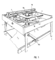
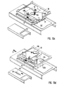
- the frame 1 of the machine according to the invention is for combined punching and positioning of dough pieces on a frame 3 supported on the ground or in a machine foundation.
- a linear guide 5 with a guide rod 7 installed, which extends parallel to the dough transport direction or to the machine side.
- a carriage 11 in or against the dough transport direction 9 slidably mounted; in the practical embodiment two guide rods 7 pass through the slide 11 via trained therein through guide bores 13.
- rodless pneumatic cylinder 15 arranged above the carriage 11 and supported against the mesh frame 1. Whose movement stroke extends parallel to the guide rod 7 of the slide linear guide 5.
- the pneumatic cylinder 15 is timely controlled or actuated to drive pin 17, both on Pneumatic cylinder 15 and on the carriage 11 to their guides extending transversely are attached, the carriage 11 in and against the dough transport direction 9 to move.
- the linear guide system can also be reversed Three-phase drive are formed, which drives the carriage through a toothed belt.
- the slide guide can be used, for example, as a linear guide be executed.
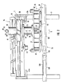
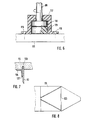
- 1 and 2 are a further pneumatic cylinder in the carriage 11 on the top 19 for impressing the punch stroke for a punch tool 21 and the underside of a tool carrier 23 for carrying and holding the punch 21 attached.
- At the upper, front end of the punch stroke pneumatic cylinder 19 is on a continuous central rod 25 at the top
- a damping disc 27 placed (according to Fig. 1, a rubber damping spring 113). This can be combined with one from above front protruding external thread 29 of the central rod 25 screwed Adjusting nut 31 as a counter bearing for adjusting the distance 32 of the cutting elements Use the punch 21 to the lower punch 33.
- the Stamping tool 21 can at the lower end of the tool carrier 23 via a (shown schematically) quick change device 35 may be attached.
- this is by two arranged symmetrically to the pivot point of the turntable 39 Guide recesses 41 realized in the given time (see below) the piston rods 43 of two in the machine room 1 opposite arranged pneumatic cylinders 45 to one of the (not shown) Control means to be threaded at a specific time.
- This will the turntable 39, when it is moved linearly by the carriage 11, simultaneously set in rotation about its axis of rotation, which also applies to the punching tool 21 is transmitted.
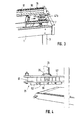
- FIG. 2 are at the rear and front dead center of the movement stroke of the Carriage 11 or on the corresponding rear and front sides of the machine frame 1 centering forks 47a, 47b attached to the respective inner walls, as can be seen more clearly from FIG. 3.
- Fig. 2 Position is between the two prongs 49 of the centering fork 47b for the dough transport direction 9 front dead center of the slide stroke a centering pin 51 indented, whereby the tool carrier 23 in or parallel to the transport direction is guided and positioned in the front dough piece storage position.
- the rear centering fork 47a in connection with the centering and fixation of the tool carrier 23 in the punching position.
- the centering bolts 51 for the two centering forks 47a, 47b are each on the underside of the turntable 39 attached.
- the front centering fork 47b positions the tool carrier so that the punch 21 with its longitudinal direction parallel to the dough transport direction 9 runs, whereas when centering through the rear centering fork 47a of the tool carrier 23 together with the punch 21 Rotated 90 ° for the punching position, with the longitudinal direction transverse to the dough transport direction 9 trending, is set (see also below).
- the punch 21 is in a cutting knife 53 on the Holding plate 55 carrying underside and a base plate 57 arranged above it with the quick-change device 35 on the upper side to the tool carrier 23 subdivided.
- the cutting plate 55 is opposite the base plate 57 in the punching stroke direction 59 by means of guide columns 61 the two longitudinal ends of the punch 21 slidably guided.
- the pillars 61 are rigidly fixed on the top of the cutting plate 55 and penetrate Guide bores 63 on the two longitudinal ends of the base plate 57. Am The upper ends of the guide columns 61 end in male thread projections 65 an adjusting nut 67 is screwed on.
- washers 71 are attached on the top and bottom of the elastomer spring 69 washers 71 are attached.
- the return stroke of the cutting plate 55 can be adjusted by means of the adjusting nut 67 adjust so that when the punching process is finished the punching stroke pneumatic cylinder 19 is deferred.
- the elastomer spring 69 is preferred made of polyurethane, and the two washers 71 between the Elastomer spring end faces on the one hand and the adjusting nut 67 or the base plate top on the other hand serve the better distribution of the pressure from the Adjusting nut 67 on the spring elements 69.
- the elastomer springs 69 can Push the cutting plate 55 upwards into a position opposite the base plate 57, in which the punch 21 with the cut dough pieces can slide over the lower die part 33.
- the punch 21 is drawn in the punching position, that is, the Cutting knives 53 protrude 73 hold-down plates with sufficient protrusion 75 plastic, for example, at the lower ends of guide rods 77 are attached and each between the mutually facing inner sides of the cutting knives 53 which form the dough piece contours.
- the guide rods 77 At the at the other end are the guide rods 77 on the underside of the base plate 57 rigidly attached and enforce from there the insert 55 in each Guide holes 79 to the hold-down plate 75 at the lower end, the holding the cut pieces of dough during transport on the Punching tool lower part 33 and stripping and ejecting the dough pieces in serve the aligned storage position (see below). With this arrangement you can the cutting knife 53 and the hold-down plate 75 relative to each other move up and down.
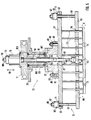
- the punching tool 21 of Carrier disks 85 When cutting into the tool carrier 23, the punching tool 21 of Carrier disks 85 immediately below the face of the screws / nut elements 83 held.
- the connecting rod 89 extends Punching tool up to the connector 91 of the piston rod 93 of the pneumatic punch stroke cylinder 19.
- the connection between the piston rod connector 91 and the connecting rod 89 of the punch 21 can accomplish by means of a (schematically indicated) cross-screw connection 95.
- the tool carrier 23 has a centering collar 87 surrounding it Screw block 97 on the top of the base plate 57 of the Punching tool 21 placed and over the guide bolt 81 with screw 83 is connected to it.
- the connecting rod 89 and the screwed thereon Connector 91 of the piston rod 93 are in a mounting cavity 99 added, which is formed within the screw block 97. It can be designed as a slot, over the lateral surface of the punch 21 is mounted centered by means of its centering collar 87.
- the screw block 97 is connected to a rotating casing 101, for example screwed, the is rotatably supported relative to an inner sleeve 105 via pivot bearing points 103.
- the inner sleeve 105 is on its upper end face with the carriage 11 on the latter Underside firmly connected, for example screwed.
- the rotational casing 101 is connected at the upper end to the turntable 39 on the upper underside, for example screwed.
- the turntable 39 if it is from Linear drive system derives its rotations, this on the tool carrier 23rd or its screw block 97 transmitted.
- Opposite that from the turntable 39 rotated casing 101 remains the core of the Tool carrier 23, the inner sleeve 105, at a standstill because of the torque due to that attached to the upper and lower ends of the inner sleeve 105 Pivot bearing 103 cannot be transferred.
- the punch-stroke pneumatic cylinder 19 is mounted for carriage 11 to bring it about of punching movements of the cutting plate 55 with the cutting knives 53. Die Punching depth can be set by means of a cylinder adjusting nut 109, which on an external thread projection 111 is screwed on, the front of the pneumatic punch stroke cylinder 19 protrudes at the upper end.
- One immediately rubber spring arranged on the lower end face of the cylinder adjusting nut 109 113 is used to dampen movement when driving to the end position.
- the connecting rod 89 of the punch 21, which at its lower End has a stamp-like extension 115, so in a plastic housing 117 recorded and rotatably mounted. This is on the top the cutting plate 55 attached, for example by screwing 119.
- a plain bearing disc 121 Inside of the plastic housing 117 immediately below the underside of the stamp extension 115 is a plain bearing disc 121, which is the axial Power transmission from the pneumatic punching cylinder 19 to the cutting plate 55 of the punch 21 is used.
- the latter is also - like the housing 117 - in particular made of plastic for reasons of noise reduction and friction.
- the base plate 57 of the punch 21 is via the screw connection 81, 83, 85 firmly connected to the rotatable part 97, 101 of the tool carrier 23.
- the possibly rotating cutting plate 55 can be by the move the pneumatic punching stroke cylinder 19 decoupled from the rotation, the guide columns 61 in the guide bores 63 of the Raise or lower the base plate 57 accordingly.
- Fig. 7 is the attachment of the cutting knife 53 in a milled knife receiving groove 123 shown enlarged.
- an L-shaped mounting bracket 125 in profile, in which the outer sides of the two L-leg screwed to the underside of the cutting plate 55 as well also on the inner wall of the cutting knife 53 by means of a weld 127 are fixed.
- FIG. 8 shows a view without or with the cutting knife removed, the in the underside of the cutting plate 55 milled receiving groove 123 with their Contour of an isosceles triangle - according to the one to be cut Piece of dough - clearly visible.
- This knife receiving groove 123 is as it were relevant as an insertion template for all cutting knives that work with each other with the greatest possible Precision must be symmetrical.
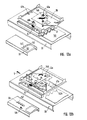
- the dough pieces are made on the first conveyor belt table 129 cut out or punched out of the continuous dough sheet.
- the second conveyor belt table 131 is used to store the dough pieces the punch 21 from the first conveyor belt table over the common one Butt or gap 133 between the two tables 129, 131 to the second conveyor belt table 131 transported downwards in the conveying direction 9 by means of the punch 21 or have been moved.
- the second conveyor belt table 131 guides the dough pieces a winding unit. 2 is in the top of the first conveyor belt feed table 129 inserted with a stiffened cutting pad 135 and with an elastomer plate, which acts as a counter bearing or punching part for the cutting knife 53 serves and for sufficient flatness and elasticity of the counterpart.
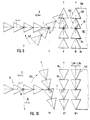
- the punching tool has four matching ones Cutting contours of an isosceles triangular shape each with the base side Bs. This runs in position W for punching parallel to the edge 139 of the continuously fed dough sheet 141 (a clocked feed is fundamental also possible).
- the axis of symmetry s of the isosceles cutting contours 137 runs in position W perpendicular to the edge of the dough band 139 or to the direction of dough transport 9.
- the assembly is started Cutting contours 137 first moved linearly in the transport direction 9 until a certain one Position X is reached, in which there is sufficient space and distance to the remaining, sawtooth-like front edge 143 of the dough band 141 remained is.
- the rotation of the punch or the assembly can start Cutting contours 137 around the between the two middle cutting contours located pivot point D can be initiated.
- the rotation takes place in the drawn Example clockwise 145. With this increasing rotation, which is approximately in or at a level corresponding to the dough sheet 141, the linear movement of the punch 21 continued such that the fulcrum on a line I in the dough transport direction 9 steadily migrates, which is appropriate corresponds to the center line or center axis of the dough sheet 141.
- Half the completion the rotary movement 145 is approximately in the angular range of 45 ° as an intermediate position Y shown.
- the pivot point or the axis of rotation D linear moved further in the direction of transport 9, and the axis of symmetry s came to congruence with the dough sheet center line I.
- the base of the isosceles triangle is again in position X1 parallel to the edge of the dough sheet 139. Since after dough piece storage according to position Z, the rotation in the same Clockwise 145 continued, is now in position X1 Stamping tool 21 with respect to the corresponding position X in Fig. 9 by exactly Rotated 180 ° so that the triangle tips (opposite the base sides Bs) directed downward in Figure 10 (while pointing upward in Figure 9 are). With a further linear return movement 10, the cutting contours can now be made precisely Congruent over the sawtooth-shaped cut out according to FIG. 9 in position W. Bring the end edge 143 of the dough sheet 141 into position, as shown in Fig. 10 labeled W1.
- FIGS. 9 and 10 are those corresponding to the process sequences just explained Movements of the turntable 39 for adjusting the punching tool 21 shown in the sense of the inventive method.
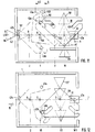
- the top view shown partially broken off in various movement stations Turntable 39 is rotatably connected to the tool carrier 23 and the punch 21 (see above) and adjusts and turns them to the W, W1 position Punch and in position Z for aligned placement.
- the fulcrum or the pivot bearing D moves - analogously to FIGS. 9 and 10 - linearly exactly on the center line I of the dough sheet to be punched out.
- the base side Bs of the cutting contours 137 runs parallel to Long side and points down in Fig. 11.
- position Z to the aligned Depositing dough pieces 147 is the turntable 39 or the composite Cutting contours 137 rotated 90 ° clockwise 145.
- the base page shows Bs of the isosceles cutting contours 137 in the dough transport direction 9 Forward; the same applies to the base side Bs of the dough pieces 147 with which a downstream winder (not shown) can be loaded immediately can.
- the turntable 39 is through the centering pin 51 exactly centered in the rear centering fork 47a so that the Cutting contours 137 congruent or flush with the sawtooth Precisely punch out the front edge 143 of the dough band 141 individual dough pieces 147 can.
- the carriage 11 is attached to it hinged turntable 39 initially only linearly in the dough transport direction 9 to position X, where the turn of the turntable is 145 mm 39 is initiated.
- the centering pin 51 ensures as long as it is in the rear centering fork 47a (route A - A1), for centered removal the dough pieces and the composite on cutting contours from the front edge of the Dough ribbon.
- position X is the initiation of rotation 145 of the turntable 39 possible.
- the control means of these the corresponding turntable pneumatic cylinder 45 so that the in Transport direction 9 right piston rod 43a is extended and engaged with the corresponding guide recess 41a of the turntable 39 can come.
- 11 is the right piston rod 43a immediately at the entrance of the right guide recess 41a, the first Start section 149 and a second end section at an angle to it 151 has.
- Piston 43a issues an increasing linear displacement of the turntable 39 Turn 145 clockwise, namely from position A2.
- the return movement 10 takes place in a purely linear manner, whereby the rear centering pin 51 in the dough transport direction 9 for symmetrical centering with respect to the center line I in the dough transport direction rear centering fork 47a indent again.
- the punching tool thus has a total rotational movement 145 180 ° clockwise so that the base sides of the isosceles Cutting contours 137 compared to the arrangement according to FIG. 11 of the others Are facing the long side of the dough sheet.
- the centering pin 51 in the rear centering fork 47a with what the new punching position W1 rotated by 180 ° has been reached.
- After punching out There remains a dough band edge on the end face, which has the sawtooth shape in FIG. 10 corresponds to that compared to the sawtooth shape of the dough band edge in FIG. 9 .mu.m Is 180 ° out of phase.
- FIGS. 9 and 10 or 11 and 12 each describe half a working cycle the punching machine, and with another linear movement from the position W1 in Dough transport direction 9, the rotation of the turntable 39 is reversed clockwise, until reaching the storage position in the dough transport direction 9 left piston rod 43b extended and for the return movement 10 then the piston rod 43a of the respective right in the dough transport direction 9 Pneumatic cylinder 45 for the turntable 39 is activated.
- the complete one The working cycle is illustrated in more detail below with reference to FIGS. 13a-d.
- the punching tool 21 waits in the position W (cf. FIGS. 9 and 11) until the dough sheet 141 is half the length of the base side Bs of the isosceles Contour triangle has been moved in the dough belt conveying direction 9.
- the precise position of stamping tool 21 together with slide 11 or turntable 39 is achieved by fixing via rotary bearing D and centering pin 51. This is necessary in order to punch out the dough pieces 147 with the same contour.
- the punching tool rotates 180 °, which also an absolute symmetry of the punching tool with respect to the axis of symmetry s (see FIGS. 9 and 10) conditionally.
- the movement of the dough band by half the base length can be recorded with a counter, which then has a corresponding Output signal to control means, whereupon the punch stroke is triggered.
- pneumatic cylinder 19 is pressurized and presses it Punching tool 21 with its cutting contours 137 or cutting knives 53 through the dough sheet 141. So that this is completely cut through, the Punch tool pad 33 in the cutting position W, W1 with a flat Plate provided as stiffened cutting pad 135, over which a rubber mat can be laid as a soft pad. This makes it possible for the cutting edge the cutting knife 53 of the punch 21 slightly below the bottom of the dough ribbon.
- the punch stroke cylinder 19 depressurized, and the knives by the spring elements 69, which during of the punching process were tensioned, withdrawn and remain insignificant stand over the lower die part 33.
- the punch stroke is the conveyor belt, if such as a punch lower part is used quietly in order to achieve the greatest possible punching accuracy. Then takes place, as in Fig. 13a with the linear dough transport direction 9 and the rotation 145 indicated clockwise, the transport of the punched out Pieces of dough 147.
- the ejection movement takes place by pressurizing the punching stroke pneumatic cylinder 19 in the reverse, direction pointing away from the surface of the dough sheet. Doing this beforehand pieces of dough 147 located between the cutting knives 53 of these free. Should pieces of dough still be pulled up between the cutting knives 53 the Niederhatlte or located above the dough pieces 147 Scraper plate the dough pieces from the cutting knives 53. According 13b, the turntable 39 becomes the linear return movement after ejection 10 issued against the dough transport direction 9, the rotating plate 39 along with Punching tool 21 is rotated further 90 ° clockwise.
- the punching tool 21 is now in a position opposite the punching position 13a positioned by 180 ° rotated position.
- the base site Bs der isosceles cutting contours or dough pieces 147 points against the in Dough transport direction 9 right edge of the dough.
- the Turntable 39 is given a counter clockwise rotation 146.
- To is the piston rod 43b on the left in the dough transport direction 9 into the associated guide recess 41b extended.
- the right piston rod 43a is in the associated Pneumatic cylinder retracted or kept inactive. The further sequence of movements takes place as explained above, but reversed by 180 °. In doing so the dough pieces 147 as shown in Fig.
- the sawtooth shape of the edge 143b of the dough sheet 141 is 180 ° with respect to the sawtooth front edge 143b according to FIG. 13b out of phase.
Claims (27)
- Procédé destiné à produire des morceaux de pâte individuels (147) à partir d'une nappe de pâte continue (141), selon lequel on découpe dans le tronçon d'extrémité de la nappe de pâte (141), une rangée de contours séparés, qui s'étend de manière oblique ou transversale à la direction longitudinale de la nappe (9, 1), les contours étant chacun fermés en soi et correspondant aux morceaux de pâte (147), ces contours ou morceaux de pâte (147) disposés côte à côte en rangée étant ensuite éloignés de l'extrémité de la nappe, et déposés pour la poursuite du traitement, en étant tournés (145, 146), basculés ou positionnés d'une autre manière, la découpe étant effectuée au moyen d'un ou de plusieurs outils de découpage (21) comportant chacun une partie supérieure (55, 57), qui présente un ou plusieurs tronçons de coupe (137) engendrant les contours, pour produire la rangée de morceaux de pâte (147), caractérisé en ce que l'outil ou les outils de découpage (21) qui ont été utilisés auparavant à l'extrémité (143) de la nappe pour le découpage de la rangée de morceaux de pâte (147), sont retirés de l'extrémité (143) de la nappe et positionnés au moyen d'un mouvement totalement ou partiellement linéaire, la rangée de morceaux de pâte (147) découpée auparavant étant maintenue entre les éléments de coupe (53) de la partie supérieure de l'outil de découpage, déplacée en translation et, à cette occasion, retirée de l'extrémité (143) de la nappe et déposée de manière positionnée, et, après la dépose (Z), l'outil ou les outils de découpage (21) sont ramenés à l'extrémité (143) de la nappe pour un nouveau découpage (W, W1).
- Procédé selon la revendication 1, caractérisé en ce qu'une partie des outils de découpage est maintenue stationnaire ou en position fixe et est utilisée pour découper une partie du contour du morceau de pâte considéré, tandis qu'une autre ou l'autre partie des outils de découpage mise en oeuvre pour le déplacement des morceaux de pâte, est utilisée pour compléter le contour du morceau de pâte considéré.
- Procédé selon la revendication 1 ou 2, caractérisé en ce que la rangée de morceaux de pâte est maintenue et guidée et/ou déplacée en translation en utilisant des dispositifs de préhension ou des dispositifs de prélèvement (Pick-up).
- Procédé selon la revendication 1, 2 ou 3, caractérisé en ce que durant et/ou après le retrait (W-X) de l'extrémité (143) de la nappe, on superpose ou on insère un mouvement de rotation et/ou de pivotement.
- Procédé selon les revendications 3 ou 3 et 4, caractérisé en ce que directement après le découpage (W, W1) des contours de morceaux de pâte (135), pour la poursuite du retrait (W-X) ou autre positionnement, guidage, maintien, rotation (145, 146) et/ou déplacement en translation des morceaux de pâte (147), la pression de la partie supérieure (55, 57) de l'outil de découpage contre la partie inférieure (33) de l'outil de découpage est rabaissée de façon telle que la partie supérieure (55, 57), avec ses arêtes de coupe, glisse et/ou peut être déplacée par-dessus la surface de la partie inférieure (33) de l'outil de découpage.
- Procédé selon les revendications 3, 3 et 4 ou 5, caractérisé en ce qu'en guise de partie inférieure d'outil de découpage (33), on utilise une bande de transport de pâte (129), dotée d'une surface résistant à la coupe.
- Procédé selon la revendication 6, caractérisé en ce que la bande de transport de pâte (129) est stoppée pendant l'opération de découpage (W, W1) des morceaux de pâte, et est à nouveau remise en mouvement et/ou déplacée de manière cadencée.
- Procédé selon les revendications 6 ou 7, caractérisé en ce qu'après chaque opération de découpage (W, W1), la bande de transport de pâte (129) est déplacée dans la direction de transport (9) de la pâte, d'une distance qui correspond à la dimension du contour ou du morceau de pâte (147) dans la direction longitudinale (1) de la nappe.
- Procédé selon la revendication 8, le contour ou le morceau de pâte (147) présentant la forme d'un triangle isocèle dont la base (Bs) s'étend dans la direction longitudinale (1) de la nappe de pâte ou parallèlement à celle-ci, et le découpage des morceaux de pâte (147) de la nappe de pâte (141) s'effectuant sans résidus de pâte, caractérisé en ce que la distance de déplacement correspond à la moitié de la longueur de la base (Bs).
- Procédé selon l'une des revendications précédentes, caractérisé en ce que plusieurs outils de découpage (53, 137) engendrant chacun un contour de morceau de pâte sont disposés côte à côte dans la zone d'extrémité (143) de la nappe de pâte, et sont actionnés et déplacés de manière combinée en commun ou individuellement, de façon mutuellement synchronisée et/ou coordonnée.
- Procédé selon l'une des revendications précédentes, les contours ou les morceaux de pâte (147) disposés côte à côte en rangées, étant retirés (W-X) de l'extrémité (143) de la nappe et déposés en ayant été tournés ou en ayant subi un pivotement (145, 146), dans l'optique de la poursuite de leur traitement, caractérisé en ce qu'au moyen de l'outil de découpage ou des outils de découpage (21), la rangée de morceaux de pâte (147) est retirée en tant qu'ensemble de l'extrémité (143) de la nappe et est déposée après rotation, le ou les moyens de découpage (21) étant ensuite à nouveau ramenés dans leur position de découpage (W, W1) et à nouveau positionnés en étant tournés (145, 146) à cette occasion.
- Procédé selon les revendications 10 et 11, caractérisé en ce que le complexe d'outils de découpage (21) avec l'ensemble découpé des morceaux de pâte (147), est orienté avec la direction longitudinale (s) dans ou parallèlement à la direction de transport (9) de la nappe de pâte.
- Procédé selon les revendications 11 ou 12, le contour ou le morceau de pâte (147) présentant la forme d'un triangle isocèle dont la base (Bs) s'étend dans la direction longitudinale (1) de la nappe de pâte, et le découpage (W, W1) des morceaux de pâte (147) de la nappe de pâte (141) s'effectuant sans résidus de pâte, caractérisé par une rotation (145, 146) de l'outil de découpage ou des outils de découpage (21) de façon telle, que les morceaux de pâte (147) soient déposés (Z) avec leur bases respectives (Bs) s'étendant transversalement à la direction de transport (9) de la pâte, et dirigées vers l'avant dans le sens de la direction de transport (9) de la pâte.
- Procédé selon l'une des revendications précédentes, caractérisé en ce qu'après le découpage (W, W1) des morceaux de pâte et avant la dépose (Z) des morceaux de pâte, l'outil de découpage (21), avec les morceaux de pâte découpés (147), est tout d'abord retiré ou éloigné linéairement (W-X) de l'extrémité de la nappe et est ensuite tourné (145, 146), et/ou après la dépose (Z) des morceaux de pâte et avant le découpage (W, W1) des morceaux de pâte, l'outil de découpage (21), sans les morceaux de pâte (147) déjà déposés, est tout d'abord tourné (145, 146) et est ensuite déplacé linéairement (10) vers l'extrémité (143) de la nappe.
- Procédé selon l'une des revendications précédentes, le contour de coupe (137) de l'outil de découpage (21) ou la forme des morceaux de pâte (147) étant symétrique par rapport à un axe central (s) qui s'étend transversalement à la direction longitudinale (1) de la nappe, caractérisé en ce qu'entre chaque opération de découpage de pâte (W, W1), l'outil de découpage (21), le cas échéant les outils du complexe d'outils de découpage sont tournés de 180°, de préférence de manière alternée dans l'un ou l'autre sens (145, 146).
- Procédé selon l'une des revendications précédentes, caractérisé en ce que pour la dépose (Z) des morceaux de pâte, on utilise des moyens d'éjection et/ou de raclage (75), que l'on fait interagir avec les arêtes de coupe de l'outil de découpage (21) en déplaçant celles-ci relativement par rapport aux moyens d'éjection et/ou de raclage (75).
- Dispositif de séparation de morceaux de pâte individuels (147) d'une nappe de pâte continue (141) conformément au procédé selon l'une des revendications précédentes, comprenant un outil de découpage (21) présentant les contours du morceau de pâte et actionné et/ou déplacé par des moyens d'entraínement (15, 19), comprenant également en regard de l'outil, une table en tant que base, support d'appui ou surface de dépôt (33) pour la nappe de pâte (141) et les morceaux de pâte (147) y ayant été découpés au moyen de l'outil de découpage (21), et comprenant également des moyens de commande agissant sur les moyens d'entraínement (15, 19) pour la coordination des composants du dispositif à déplacer ou à entraíner, caractérisé par des moyens de guidage (5, D, 61) qui supportent l'outil de découpage (21) et qui sont couplés avec les moyens d'entraínement et/ou de commande et s'entendent parallèlement au côté supérieur de la table de manière telle, que l'outil de découpage (21) puisse, avec les morceaux de pâte (147) découpés, glisser directement sur le côté supérieur de la table et le long de celui-ci, et puisse être retiré ou éloigné (W-X) de l'extrémité (143) de la nappe de pâte et être tourné ou subir un pivotement (145, 146).
- Dispositif selon la revendication 17 pour la mise en oeuvre du procédé selon la revendication 16, caractérisé en ce que l'outil de découpage (21) est doté d'éléments d'éjection et/ou de support (raclage) de la pâte (75), qui interagissent avec ses éléments de coupe (53), et les éléments d'éjection et/ou de support (raclage) de la pâte (75) et les éléments de coupe (53) sont montés de manière à pouvoir être déplacés (rappelés de manière élastique) réciproquement par les moyens d'entraínement (19) et/ou un élément de ressort (69), en vue d'éjecter le morceau de pâte (147) considéré d'entre les éléments de coupe (53) et/ou de l'en séparer par raclage.
- Dispositif selon la revendication 17 ou 18, caractérisé en ce que l'outil de découpage (21) est réalisé avec une plaque de support ou plaque de coupe (55) portant les éléments de coupe (53), dont le côté dirigé vers les éléments de coupe (53) est pourvu d'une ou de plusieurs rainures de réception (123) pour les éléments de coupe (53), qui s'étendent conformément au contour des morceaux de pâte.
- Dispositif selon l'une des revendications précédentes, caractérisé en ce que les moyens d'entraínement (15, 19) comportent un dispositif de pression ou d'actionnement (19) dirigé vers la nappe de pâte et, opposé et/ou agissant à l'encontre de celui-ci, un dispositif de rappel (69), avec lesquels sont reliés respectivement les éléments de coupe (53) de l'outil de découpage (21), le déplacement de rappel (G) engendré par le dispositif de rappel (69) pour les éléments de coupe (53) étant dimensionné de manière telle, que les éléments de coupe (53) quittent leur prise par complémentarité de forme avec le côté supérieur de la table, mais de façon telle que l'outil de découpage (21) avec les morceaux de pâte découpés (147) reste toutefois en prise par adhérence et/ou en contact de glissement avec le côté supérieur de la table.
- Dispositif selon l'une des revendications précédentes, caractérisé en ce que la table (33) est formée par une ou plusieurs bandes de transport (129, 131) dont le déplacement de transport est commandé ou régulé par les moyens d'entraínement et de commande, en fonction de la position et/ou de l'état de l'outil de découpage (21).
- Dispositif selon la revendication 21, caractérisé par au moins deux bandes de transport (129, 131) disposées l'une à la suite de l'autre dans la direction de transport de la pâte (9), dont la première (129) est affectée à l'opération de découpage ou de coupe (W, W1); et la seconde (131) à l'opération de dépose (Z) du morceau de pâte.
- Dispositif selon l'une des revendications précédentes, caractérisé en ce que les moyens de guidage (5, D, 61) comprennent un guidage linéaire (5) qui s'étend dans ou parallèlement à la direction de transport (9), de l'extrémité (143) de la nappe de pâte jusqu'au lieu du dépôt (Z) des morceaux de pâte, et dans lequel est monté de manière à pouvoir y coulisser en va-et-vient, un chariot (11) portant l'outil de découpage (21) lié au chariot, les moyens de guidage comprenant également un palier de rotation (D, 103) disposé dans ou sur le chariot (11) et dans lequel est monté en rotation (145, 146) l'outil de découpage (21), et en ce que les moyens d'entraínement (15, 19) comportent un module d'entraínement linéaire (15) déplaçant le chariot (11), et un module d'entraínement en rotation faisant tourner l'outil de découpage (21), ces modules étant reliés aux moyens de commande, en vue de leur coordination et/ou synchronisation.
- Dispositif selon la revendication 23, caractérisé en ce que le module d'entraínement en rotation est réalisé à l'aide d'un disque de rotation (39), qui est couplé ou relié en rotation à l'outil de découpage (21), et qui présente des éléments de butée et/ou d'entraínement (43a, 43b) auxquels sont associés des éléments de butée et/ou d'entraínement conjugués (41a, 41b) en position fixe, pour la prise par adhérence ou par complémentarité de forme, ou pour un autre couplage.
- Dispositif selon la revendication 23, caractérisé en ce que le module d'entraínement en rotation est réalisé à l'aide d'un moteur de rotation, qui est coordonné et/ou synchronisé avec le module d'entraínement linéaire (15), par l'intermédiaire des moyens de commande.
- Dispositif selon l'une des revendications précédentes, caractérisé en ce que l'outil de découpage (21) possède une première plaque de support ou de coupe (55) présentant des éléments de coupe (53) avec le contour des morceaux de pâte, et une seconde plaque de support ou de base (57) présentant des éléments d'éjection et/ou de support (raclage) de la pâte (75), ces deux plaques de support (55, 57) étant reliées de manière à pouvoir être déplacées réciproquement dans la direction de la course de découpage (59), les éléments d'éjection et/ou de support (raclage) de la pâte (75) étant disposés directement à côté des éléments de coupe (53) et/ou de manière à pouvoir glisser sur ceux-ci avec une course de déplacement qui s'étend de part et d'autre de l'arête de coupe de l'élément de coupe (53).
- Outil de découpage selon la revendication 26, caractérisé par plusieurs montants (61) et/ou tiges (77) servant à assurer la liaison des deux plaques (55, 57), qui, à l'une de leurs extrémités sont fixés en partie à l'une et en partie à l'autre des deux plaques (55, 57), et qui traversent respectivement l'autre plaque (55, 57) en étant mobiles dans la direction longitudinale et la direction de la course de découpage (59), les montants et/ou tiges présentant à leur autre extrémité, les éléments d'éjection et/ou de support (raclage) de la pâte (75) ou des éléments de ressort (69) qui prennent appui sur le côté de plaque le plus proche.
Applications Claiming Priority (5)
| Application Number | Priority Date | Filing Date | Title |
|---|---|---|---|
| DE19716159 | 1997-04-18 | ||
| DE19716159 | 1997-04-18 | ||
| DE19720689A DE19720689A1 (de) | 1997-04-18 | 1997-05-16 | Verfahren und Vorrichtung sowie Stanzwerkzeug zur Herstellung von einzelnen Teigstücken aus seiner kontinuierlichen Teigbahn |
| DE19720689 | 1997-05-16 | ||
| PCT/EP1998/001592 WO1998047378A1 (fr) | 1997-04-18 | 1998-03-18 | Procede, dispositif et outil de decoupage pour la production de morceaux de pâte individuels a partir d'une bande de pâte continue |
Publications (2)
| Publication Number | Publication Date |
|---|---|
| EP0910248A1 EP0910248A1 (fr) | 1999-04-28 |
| EP0910248B1 true EP0910248B1 (fr) | 2001-10-31 |
Family
ID=26035864
Family Applications (1)
| Application Number | Title | Priority Date | Filing Date |
|---|---|---|---|
| EP98912488A Expired - Lifetime EP0910248B1 (fr) | 1997-04-18 | 1998-03-18 | Procede, dispositif et outil de decoupage pour la production de morceaux de pate individuels a partir d'une bande de pate continue |
Country Status (6)
| Country | Link |
|---|---|
| US (1) | US6158315A (fr) |
| EP (1) | EP0910248B1 (fr) |
| JP (1) | JP3463172B2 (fr) |
| DK (1) | DK0910248T3 (fr) |
| ES (1) | ES2162703T3 (fr) |
| WO (1) | WO1998047378A1 (fr) |
Families Citing this family (17)
| Publication number | Priority date | Publication date | Assignee | Title |
|---|---|---|---|---|
| US6619173B2 (en) * | 2001-08-07 | 2003-09-16 | Masco Corporation Taylor | Vibratory fiber chopper |
| US20030221535A1 (en) * | 2002-04-01 | 2003-12-04 | Sargento Foods Inc. | Structure and method for cutting slabs of natural cheeses into shape (s) via cutting blades of a pattern such that the shape (s) are tessellated or nested |
| US20040052907A1 (en) * | 2002-09-18 | 2004-03-18 | Maniak Douglas C. | Vertically oriented laminated dough product |
| US6953596B2 (en) * | 2002-09-18 | 2005-10-11 | General Mills, Inc. | Method and apparatus for cutting dough with nested pattern cutters |
| US6745672B1 (en) * | 2002-11-15 | 2004-06-08 | The Pillsbury Company | Transport module for handling softened dough intermediates |
| ATE477731T1 (de) * | 2004-05-12 | 2010-09-15 | Koninkl Philips Electronics Nv | Vorrichtung zur zubereitung eines heissgetränks mit einem kessel und verbindungsmitteln zum anschluss des kessels an ein gehäuse der vorrichtung |
| US20070292575A1 (en) * | 2004-09-23 | 2007-12-20 | Alon Ofir | Machinery And Method For Manufacturing Shaped Pita Bread |
| ITVR20050042A1 (it) * | 2005-04-05 | 2006-10-06 | Doge Food Proc Machinery S R L | Dispositivo di distanziamento e di allineamento, particolarmente per linee di produzione e di trattamento di prodotti alimentari arrotolati |
| ITVI20080238A1 (it) * | 2008-10-13 | 2010-04-14 | Iteca S P A | Apparato per la formatura di elementi discoidali di pasta alimentare. |
| ITVR20090113A1 (it) * | 2009-07-24 | 2011-01-25 | Rondo Schio S R L | Dispositivo di distanziamento e di allineamento, particolarmente per linee di produzione e di trattamento di prodotti alimentari arrotolati |
| US20120207899A1 (en) * | 2011-02-15 | 2012-08-16 | Boris Serebryany | Method and apparatus for cutting dough products having holes from a dough sheet |
| JP6121344B2 (ja) * | 2014-02-07 | 2017-04-26 | レオン自動機株式会社 | 食品生地切断片の整列配置装置 |
| US9314405B2 (en) * | 2014-03-17 | 2016-04-19 | Teresa Y. Smith | Multiple pill cutter |
| DE102014005998B3 (de) * | 2014-04-28 | 2015-05-13 | Fritsch Gmbh | Verfahren und Vorrichtung zur Erzeugung von Zuschnitten von Teigstücken aus einer oder mehreren Teigbahnen |
| JP6407667B2 (ja) * | 2014-11-11 | 2018-10-17 | レオン自動機株式会社 | 食品生地片の切断移送装置および方法 |
| US9834384B2 (en) * | 2016-01-23 | 2017-12-05 | John Bean Technologies Corporation | Gap adjustment assembly for blade portioner conveyors |
| FR3047150B1 (fr) * | 2016-02-03 | 2018-02-16 | Ekim | Dispositif de formage d'une pate abaissee a partir d'un paton par pressage |
Family Cites Families (6)
| Publication number | Priority date | Publication date | Assignee | Title |
|---|---|---|---|---|
| JPS55156543A (en) * | 1979-05-24 | 1980-12-05 | Rheon Automatic Machinery Co | Apparatus for changing advancing direction of dough strip |
| IT1190555B (it) * | 1986-03-19 | 1988-02-16 | Ferrero Spa | Dispositivo di presa particolarmente per apparecchiature automatiche di sollevamento e trasporto di impianti per il confezionamento di prodotti alimentari |
| DE3903746C1 (fr) | 1989-02-09 | 1990-05-31 | A. Fritsch Gmbh & Co Kg, 8711 Markt Einersheim, De | |
| JP2567296B2 (ja) * | 1990-10-23 | 1996-12-25 | レオン自動機 株式会社 | クロワッサン生地片の拡開、方向変換方法及び装置 |
| US5365816A (en) * | 1993-06-22 | 1994-11-22 | Design Systems, Inc. | Beam cutter |
| JP2747777B2 (ja) * | 1993-10-08 | 1998-05-06 | レオン自動機株式会社 | クロワッサン生地の調心装置 |
-
1998
- 1998-03-18 JP JP54484798A patent/JP3463172B2/ja not_active Expired - Lifetime
- 1998-03-18 EP EP98912488A patent/EP0910248B1/fr not_active Expired - Lifetime
- 1998-03-18 ES ES98912488T patent/ES2162703T3/es not_active Expired - Lifetime
- 1998-03-18 US US09/194,713 patent/US6158315A/en not_active Expired - Lifetime
- 1998-03-18 WO PCT/EP1998/001592 patent/WO1998047378A1/fr active IP Right Grant
- 1998-03-18 DK DK98912488T patent/DK0910248T3/da active
Also Published As
| Publication number | Publication date |
|---|---|
| DK0910248T3 (da) | 2002-02-25 |
| EP0910248A1 (fr) | 1999-04-28 |
| ES2162703T3 (es) | 2002-01-01 |
| JP3463172B2 (ja) | 2003-11-05 |
| JP2000512509A (ja) | 2000-09-26 |
| WO1998047378A1 (fr) | 1998-10-29 |
| US6158315A (en) | 2000-12-12 |
Similar Documents
| Publication | Publication Date | Title |
|---|---|---|
| EP0910248B1 (fr) | Procede, dispositif et outil de decoupage pour la production de morceaux de pate individuels a partir d'une bande de pate continue | |
| DE1213788B (de) | Werkstueckfoerdervorrichtung, z. B. fuer Stufenpressen | |
| EP0491658A1 (fr) | Procédé et dispositif pour déformer sous forme d'ondulation un matériau en feuilles | |
| DE2252047B2 (de) | Vorrichtung zum Zerschneiden eines kontinuierlich bewegten Bandes aus plastisch verformbarem Material in einzelne Formstücke, beispielsweise Betonziegel | |
| EP0422332B1 (fr) | Dispositif pour apposer des renforts sur des intercalaires d'indexage | |
| DE2728647A1 (de) | Formteilpresse | |
| EP1877233A2 (fr) | Dispositif pour separer un boudin d'argile plastique au moyen d'un dispositif d'entaille agissant sur tous les cotes | |
| DE19720689A1 (de) | Verfahren und Vorrichtung sowie Stanzwerkzeug zur Herstellung von einzelnen Teigstücken aus seiner kontinuierlichen Teigbahn | |
| DE4127779C2 (de) | Vorrichtung zum Vorschub eines Abschnitts einer dünnen Materialbahn mit vorbestimmter Schrittlänge | |
| EP2061610A1 (fr) | Dispositif de découpage et procédé de découpage | |
| DE2643507A1 (de) | Vorrichtung zum schrittweisen vorschub von platten | |
| EP0882400B1 (fr) | Procédé de fabrication de pièces individuelles de pâte et outil de coupe et/ou de poinçonnage associé | |
| DE2518359A1 (de) | Holzbearbeitungs-maschine | |
| DE2917387C3 (de) | Tiefziehmaschine zum Herstellen von Behältern aus thermoplastischer Folie | |
| DE1153234B (de) | Vorrichtung zur Herstellung von Faltschachteln | |
| DE2654000C3 (de) | Maschine zum Ausbrechen von Nutzen | |
| DE2351069C3 (de) | Maschine zum Aufteilen von Folien, Platten, Tabletts oder anderen Gegenständen in Quer- und Längsrichtung | |
| DE10129429C2 (de) | Vorrichtung zur Schneidbearbeitung eines bahnförmigen Werkstücks | |
| DE2817597A1 (de) | Verfahren und vorrichtung zum verbinden aufeinanderfolgender materialbahnen | |
| DE2152784A1 (de) | Vorrichtung und Verfahren zum Einsetzen von Einpreßmuttern in ein Werkstück | |
| DE3314459C2 (de) | Siloblockschneider | |
| DE862831C (de) | Maschine zur Herstellung von Knoepfen aus plattenfoermigem Werkstoff | |
| DE19620597C2 (de) | Vorrichtung zur Bearbeitung von Lagenmaterial | |
| DE2525896A1 (de) | Verstellbarer anschlag zum aufstellen eines zu bearbeitenden werkstuecks auf einer werkzeugmaschine | |
| DE1216814B (de) | Grossflaechenstanzmaschine |
Legal Events
| Date | Code | Title | Description |
|---|---|---|---|
| PUAI | Public reference made under article 153(3) epc to a published international application that has entered the european phase |
Free format text: ORIGINAL CODE: 0009012 |
|
| 17P | Request for examination filed |
Effective date: 19981016 |
|
| AK | Designated contracting states |
Kind code of ref document: A1 Designated state(s): CH DE DK ES FR GB IT LI NL |
|
| 17Q | First examination report despatched |
Effective date: 19991210 |
|
| GRAG | Despatch of communication of intention to grant |
Free format text: ORIGINAL CODE: EPIDOS AGRA |
|
| GRAG | Despatch of communication of intention to grant |
Free format text: ORIGINAL CODE: EPIDOS AGRA |
|
| GRAH | Despatch of communication of intention to grant a patent |
Free format text: ORIGINAL CODE: EPIDOS IGRA |
|
| GRAH | Despatch of communication of intention to grant a patent |
Free format text: ORIGINAL CODE: EPIDOS IGRA |
|
| GRAA | (expected) grant |
Free format text: ORIGINAL CODE: 0009210 |
|
| AK | Designated contracting states |
Kind code of ref document: B1 Designated state(s): CH DE DK ES FR GB IT LI NL |
|
| REG | Reference to a national code |
Ref country code: CH Ref legal event code: EP |
|
| REG | Reference to a national code |
Ref country code: CH Ref legal event code: NV Representative=s name: ISLER & PEDRAZZINI AG |
|
| REF | Corresponds to: |
Ref document number: 59801937 Country of ref document: DE Date of ref document: 20011206 |
|
| REG | Reference to a national code |
Ref country code: GB Ref legal event code: IF02 Ref country code: ES Ref legal event code: FG2A Ref document number: 2162703 Country of ref document: ES Kind code of ref document: T3 |
|
| GBT | Gb: translation of ep patent filed (gb section 77(6)(a)/1977) |
Effective date: 20020130 |
|
| REG | Reference to a national code |
Ref country code: DK Ref legal event code: T3 |
|
| ET | Fr: translation filed | ||
| PLBE | No opposition filed within time limit |
Free format text: ORIGINAL CODE: 0009261 |
|
| STAA | Information on the status of an ep patent application or granted ep patent |
Free format text: STATUS: NO OPPOSITION FILED WITHIN TIME LIMIT |
|
| 26N | No opposition filed | ||
| PG25 | Lapsed in a contracting state [announced via postgrant information from national office to epo] |
Ref country code: IT Free format text: LAPSE BECAUSE OF NON-PAYMENT OF DUE FEES;WARNING: LAPSES OF ITALIAN PATENTS WITH EFFECTIVE DATE BEFORE 2007 MAY HAVE OCCURRED AT ANY TIME BEFORE 2007. THE CORRECT EFFECTIVE DATE MAY BE DIFFERENT FROM THE ONE RECORDED. Effective date: 20050318 |
|
| REG | Reference to a national code |
Ref country code: CH Ref legal event code: PCAR Free format text: ISLER & PEDRAZZINI AG;POSTFACH 1772;8027 ZUERICH (CH) |
|
| PGRI | Patent reinstated in contracting state [announced from national office to epo] |
Ref country code: IT Effective date: 20091001 |
|
| REG | Reference to a national code |
Ref country code: FR Ref legal event code: PLFP Year of fee payment: 19 |
|
| REG | Reference to a national code |
Ref country code: FR Ref legal event code: PLFP Year of fee payment: 20 |
|
| PGFP | Annual fee paid to national office [announced via postgrant information from national office to epo] |
Ref country code: FR Payment date: 20170323 Year of fee payment: 20 Ref country code: NL Payment date: 20170323 Year of fee payment: 20 Ref country code: CH Payment date: 20170327 Year of fee payment: 20 |
|
| PGFP | Annual fee paid to national office [announced via postgrant information from national office to epo] |
Ref country code: GB Payment date: 20170327 Year of fee payment: 20 Ref country code: DK Payment date: 20170327 Year of fee payment: 20 |
|
| PGFP | Annual fee paid to national office [announced via postgrant information from national office to epo] |
Ref country code: DE Payment date: 20170522 Year of fee payment: 20 |
|
| PGFP | Annual fee paid to national office [announced via postgrant information from national office to epo] |
Ref country code: IT Payment date: 20170323 Year of fee payment: 20 Ref country code: ES Payment date: 20170323 Year of fee payment: 20 |
|
| REG | Reference to a national code |
Ref country code: DE Ref legal event code: R071 Ref document number: 59801937 Country of ref document: DE |
|
| REG | Reference to a national code |
Ref country code: DK Ref legal event code: EUP Effective date: 20180318 |
|
| REG | Reference to a national code |
Ref country code: NL Ref legal event code: MK Effective date: 20180317 |
|
| REG | Reference to a national code |
Ref country code: CH Ref legal event code: PL |
|
| REG | Reference to a national code |
Ref country code: GB Ref legal event code: PE20 Expiry date: 20180317 |
|
| PG25 | Lapsed in a contracting state [announced via postgrant information from national office to epo] |
Ref country code: GB Free format text: LAPSE BECAUSE OF EXPIRATION OF PROTECTION Effective date: 20180317 |
|
| REG | Reference to a national code |
Ref country code: ES Ref legal event code: FD2A Effective date: 20200724 |
|
| PG25 | Lapsed in a contracting state [announced via postgrant information from national office to epo] |
Ref country code: ES Free format text: LAPSE BECAUSE OF EXPIRATION OF PROTECTION Effective date: 20180319 |